trane diffusers 1104
DESCRIPTION
sdgsdgTRANSCRIPT
VAV-PRC008-EN D 1
Introduction D 2 – 3
Linear Slot Diffusers (LINR) D 4 – 11
Adjustable Flow Diffusers (FAPF, VAPF, AABD, VAPS) D 12 – 21
Light Fixture Diffusers (LITE) D 22 – 26
Induction Diffusers (INDT, INDB, INCB, INSR) D 27 – 29
Perforated Diffusers (PERF) D 30 – 32
Mechanical Specifications D 33 – 34
IntroductionIn today’s diverse buildingenvironment, we are seeing anexpanding role of VAV applicationsacross many different marketsegments. While this is happening,it is necessary to make sure the VAVsystems and diffusers in particularare applied, installed, and operatedcorrectly.
The purpose of this section of thecatalog is to show these issues thatneed to be considered when selectingand placing diffusers.
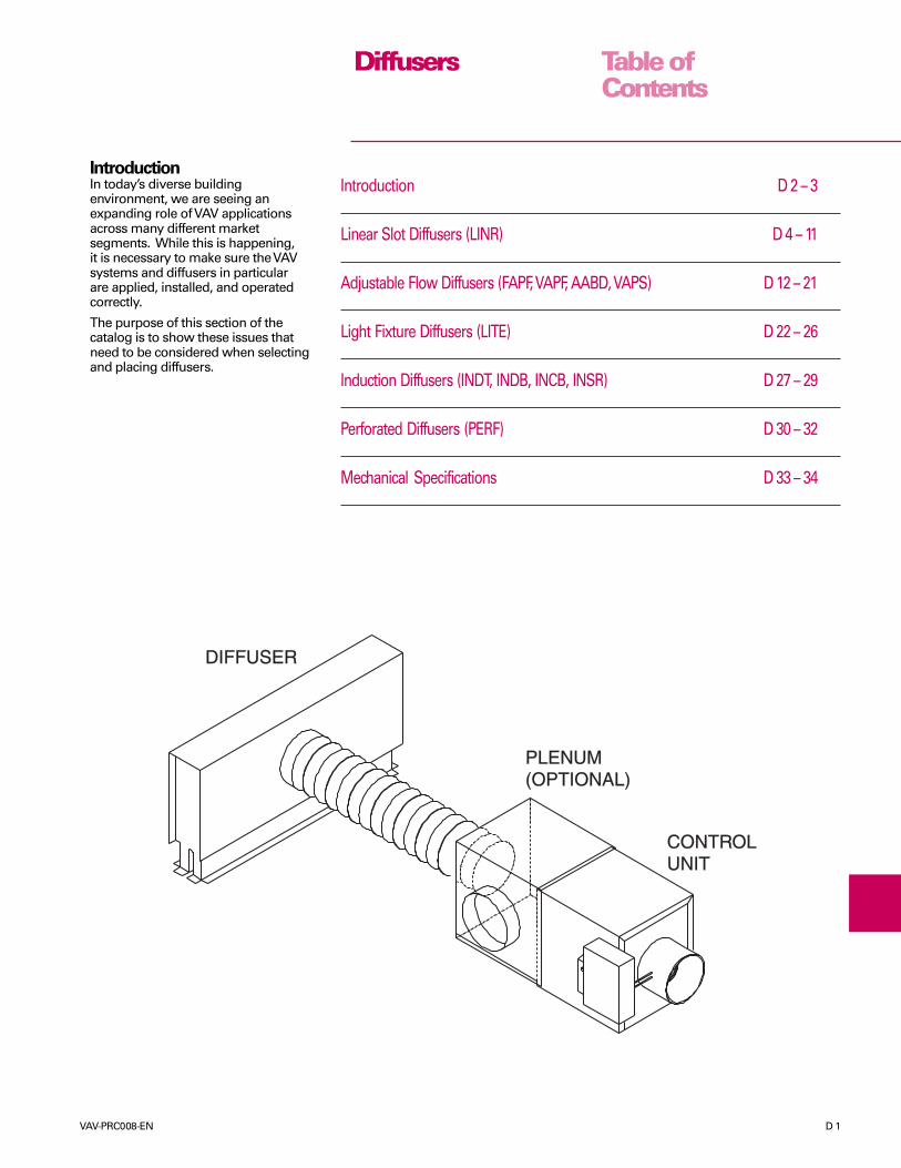
DIFFUSER
PLENUM(OPTIONAL)
CONTROLUNIT
Table ofContents
Diffusers

D 2 VAV-PRC008-EN
DiffusersThe VariTrane line of variable-air-volume (VAV) products has been anindustry leader in performance andquality for many years. While mostwould associate the VariTrane namewith VAV terminal units, the diffuserproduct line has grown significantlyover the years.
Room Air DistributionWhen variable-flow cooling andconstant-flow heating are combined ina zone, the zone air diffusers areusually selected at partial cooling loadto ensure proper operation. Ceiling-mounted linear slot diffusers arerecommended since they perform wellover a wide range of velocities. Cool airdelivery takes advantage of the“Coanda” effect, whereby cool airdischarged through a linear slotdiffuser hugs the ceiling beforedescending, insuring proper operationover a wide range of flows without“dumping.” When delivering warm airwith constant flow velocities, or warm/cool air with variable flow velocities,the flow velocity must be high enoughto ensure that the air reaches the floor.To prevent stratification, the warm airtemperature should not be more than20°F (6.7°C) above the zone airtemperature.
In addition to choosing the correctdiffuser type, the designer mustproperly size and place each diffuser inthe zone to minimize noise andpressure drop while maximizing thethrow and diffusion performance.
VariTrane Diffuser TypesThe VariTrane line of diffusers containsa variety of different models. Thefollowing is a list of the diffuser types
in the VariTrane line,an explanation ofeach type, and a shortdiscussion of theproper application foreach type.
Linear Slot Diffuser(LINR)Linear slot diffusersare most commonlyused in VAV systems.
SUPPLSUPPLYAIR DIFFUSERSAIR DIFFUSERS
RETURNRETURNAIRAIRDIFFUSERDIFFUSER
NEVER DO NEVER DO THIS!!THIS!!(PERPENDICULAR AIR FLOWS)
nominal airflow. If you start by using100% of the nominal airflow, you willend up with high losses inperformance, acoustical problems, andvery little or no design flexibility.
A diffuser airflow rate is 50 cfm perlinear foot (77.4 L/s per linear meter) ofdiffuser. Therefore, the recommendedflow to use when designing is 50 cfm/linear ft x 0.8 = 40 cfm/linear ft (77.4 L/s/linear m x 0.8 = 61.9 L/s/linear m).
The nominal airflow of a diffuser isdetermined by multiplying the diffuserlength, the number of slots, and theairflow per linear foot. Using theairflow per linear foot calculated above,a 4 foot, 2-slot, 2-way diffuser shouldbe designed to handle 4 linear ft x 2slots x 40 cfm/linear ft = 320 cfm(1.219 m x 2 slots x 61.9 L/s/linear m =150.9 L/s).
To maximize the effectiveness ofventilation with ceiling diffusers,throws should be kept as long aspossible. For proper air circulation, tryto maintain at least a 20°F (6.7°C)difference between the supply air androom temperature. This provides foroptimum performance.
Collision Velocities –The collisionvelocity is the speed at which movingair meets a wall or another airflow
This type of diffuser has a fixed vaneinside, which means that the pattern isnot adjustable. The fixed vane allows awide range of flows through thediffuser without causing drafts. Lowerflanges provide ceiling tile support asan integral part of the diffuser housing.
Recommended Guidelines—LinearSlot DiffusersDiffuser Placement – The maximumrecommended distance betweendiffusers is three diffuser lengths. Forexample, if the diffuser length is 4 feet(1.219 m), the maximum separationdistance would be 4 ft x 3 = 12ft(1.219 m x 3 = 3.658 m).
The maximum recommended distancefor diffusers from an exterior wall, withparallel flow to the wall is two diffuserlengths. For example, if the diffuserlength is 4 feet (1.219 m), themaximum distance from the exteriorwall would be 4 ft x 2 = 8 ft(1.219 m x 2 = 2.438 m).
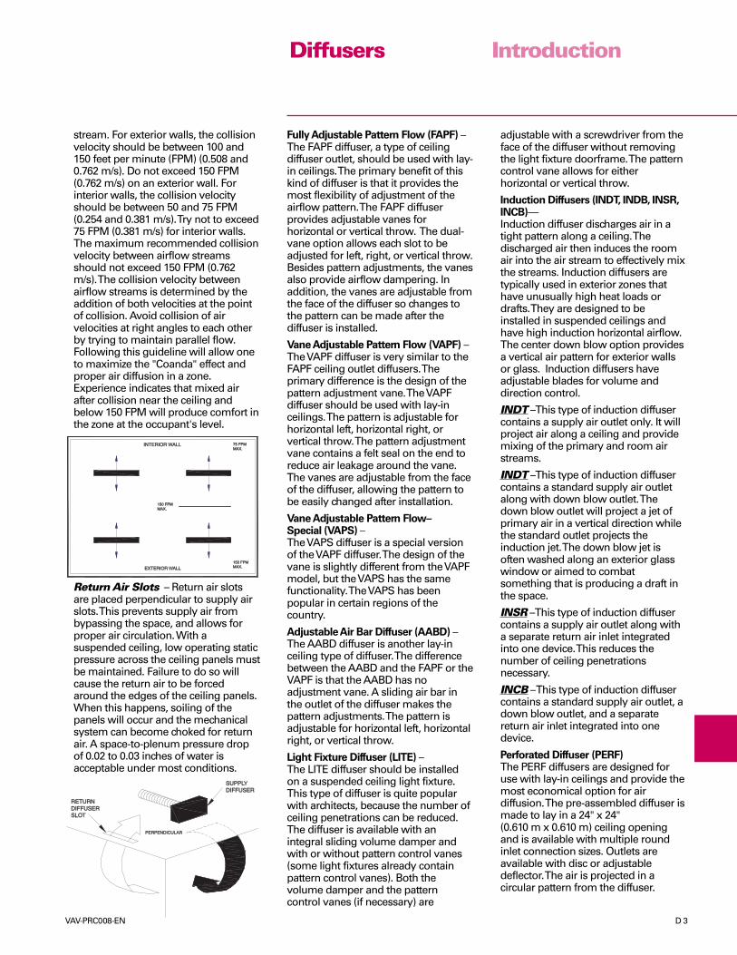
A simple rule for better air circulation isto avoid placing supply air linear slotdiffusers that allow airflows to collideat right angles.
General Guidelines – Whenbeginning the placement and layout ofdiffusers, assume that each diffuserdelivers only 75% to 80% of its
Diffusers Introduction
VAV-PRC008-EN D 3
INTERIOR INTERIOR WALLALL 75 FPM75 FPMMAX.MAX.
150 FPM150 FPMMAX.MAX.
150 FPM150 FPMMAX.MAX.EXTERIOR EXTERIOR WALLALL
stream. For exterior walls, the collisionvelocity should be between 100 and150 feet per minute (FPM) (0.508 and0.762 m/s). Do not exceed 150 FPM(0.762 m/s) on an exterior wall. Forinterior walls, the collision velocityshould be between 50 and 75 FPM(0.254 and 0.381 m/s). Try not to exceed75 FPM (0.381 m/s) for interior walls.The maximum recommended collisionvelocity between airflow streamsshould not exceed 150 FPM (0.762m/s). The collision velocity betweenairflow streams is determined by theaddition of both velocities at the pointof collision. Avoid collision of airvelocities at right angles to each otherby trying to maintain parallel flow.Following this guideline will allow oneto maximize the "Coanda" effect andproper air diffusion in a zone.Experience indicates that mixed airafter collision near the ceiling andbelow 150 FPM will produce comfort inthe zone at the occupant's level.
Return Air Slots – Return air slotsare placed perpendicular to supply airslots. This prevents supply air frombypassing the space, and allows forproper air circulation. With asuspended ceiling, low operating staticpressure across the ceiling panels mustbe maintained. Failure to do so willcause the return air to be forcedaround the edges of the ceiling panels.When this happens, soiling of thepanels will occur and the mechanicalsystem can become choked for returnair. A space-to-plenum pressure dropof 0.02 to 0.03 inches of water isacceptable under most conditions.
RETURNRETURNDIFFUSERDIFFUSERSLOSLOT
SUPPLSUPPLYDIFFUSERDIFFUSER
PERPENDICULARPERPENDICULAR
Fully Adjustable Pattern Flow (FAPF) –The FAPF diffuser, a type of ceilingdiffuser outlet, should be used with lay-in ceilings. The primary benefit of thiskind of diffuser is that it provides themost flexibility of adjustment of theairflow pattern. The FAPF diffuserprovides adjustable vanes forhorizontal or vertical throw. The dual-vane option allows each slot to beadjusted for left, right, or vertical throw.Besides pattern adjustments, the vanesalso provide airflow dampering. Inaddition, the vanes are adjustable fromthe face of the diffuser so changes tothe pattern can be made after thediffuser is installed.
Vane Adjustable Pattern Flow (VAPF) –The VAPF diffuser is very similar to theFAPF ceiling outlet diffusers. Theprimary difference is the design of thepattern adjustment vane. The VAPFdiffuser should be used with lay-inceilings. The pattern is adjustable forhorizontal left, horizontal right, orvertical throw. The pattern adjustmentvane contains a felt seal on the end toreduce air leakage around the vane.The vanes are adjustable from the faceof the diffuser, allowing the pattern tobe easily changed after installation.
Vane Adjustable Pattern Flow–Special (VAPS) –The VAPS diffuser is a special versionof the VAPF diffuser. The design of thevane is slightly different from the VAPFmodel, but the VAPS has the samefunctionality. The VAPS has beenpopular in certain regions of thecountry.
Adjustable Air Bar Diffuser (AABD) –The AABD diffuser is another lay-inceiling type of diffuser. The differencebetween the AABD and the FAPF or theVAPF is that the AABD has noadjustment vane. A sliding air bar inthe outlet of the diffuser makes thepattern adjustments. The pattern isadjustable for horizontal left, horizontalright, or vertical throw.
Light Fixture Diffuser (LITE) –The LITE diffuser should be installedon a suspended ceiling light fixture.This type of diffuser is quite popularwith architects, because the number ofceiling penetrations can be reduced.The diffuser is available with anintegral sliding volume damper andwith or without pattern control vanes(some light fixtures already containpattern control vanes). Both thevolume damper and the patterncontrol vanes (if necessary) are
adjustable with a screwdriver from theface of the diffuser without removingthe light fixture doorframe. The patterncontrol vane allows for eitherhorizontal or vertical throw.
Induction Diffusers (INDT, INDB, INSR,INCB)—Induction diffuser discharges air in atight pattern along a ceiling. Thedischarged air then induces the roomair into the air stream to effectively mixthe streams. Induction diffusers aretypically used in exterior zones thathave unusually high heat loads ordrafts. They are designed to beinstalled in suspended ceilings andhave high induction horizontal airflow.The center down blow option providesa vertical air pattern for exterior wallsor glass. Induction diffusers haveadjustable blades for volume anddirection control.
INDT –This type of induction diffusercontains a supply air outlet only. It willproject air along a ceiling and providemixing of the primary and room airstreams.
INDT –This type of induction diffusercontains a standard supply air outletalong with down blow outlet. Thedown blow outlet will project a jet ofprimary air in a vertical direction whilethe standard outlet projects theinduction jet. The down blow jet isoften washed along an exterior glasswindow or aimed to combatsomething that is producing a draft inthe space.
INSR –This type of induction diffusercontains a supply air outlet along witha separate return air inlet integratedinto one device. This reduces thenumber of ceiling penetrationsnecessary.
INCB – This type of induction diffusercontains a standard supply air outlet, adown blow outlet, and a separatereturn air inlet integrated into onedevice.
Perforated Diffuser (PERF)The PERF diffusers are designed foruse with lay-in ceilings and provide themost economical option for airdiffusion. The pre-assembled diffuser ismade to lay in a 24" x 24"(0.610 m x 0.610 m) ceiling openingand is available with multiple roundinlet connection sizes. Outlets areavailable with disc or adjustabledeflector. The air is projected in acircular pattern from the diffuser.
Diffusers Introduction
D 4 VAV-PRC008-EN
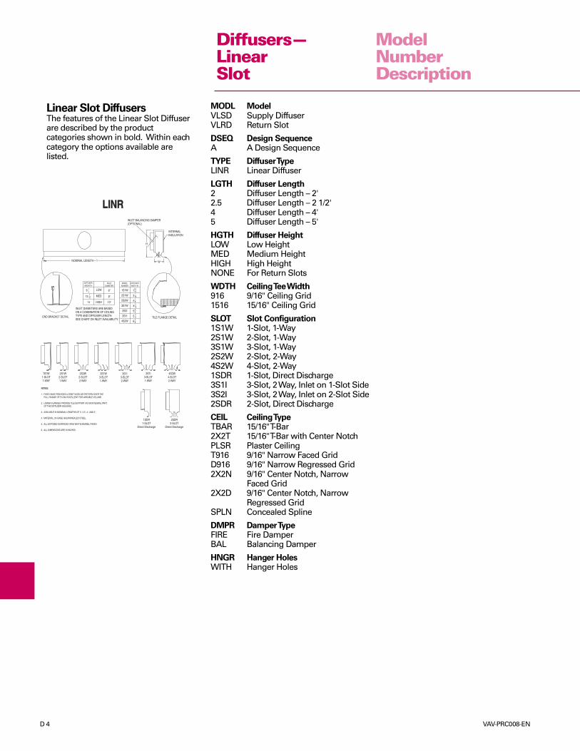
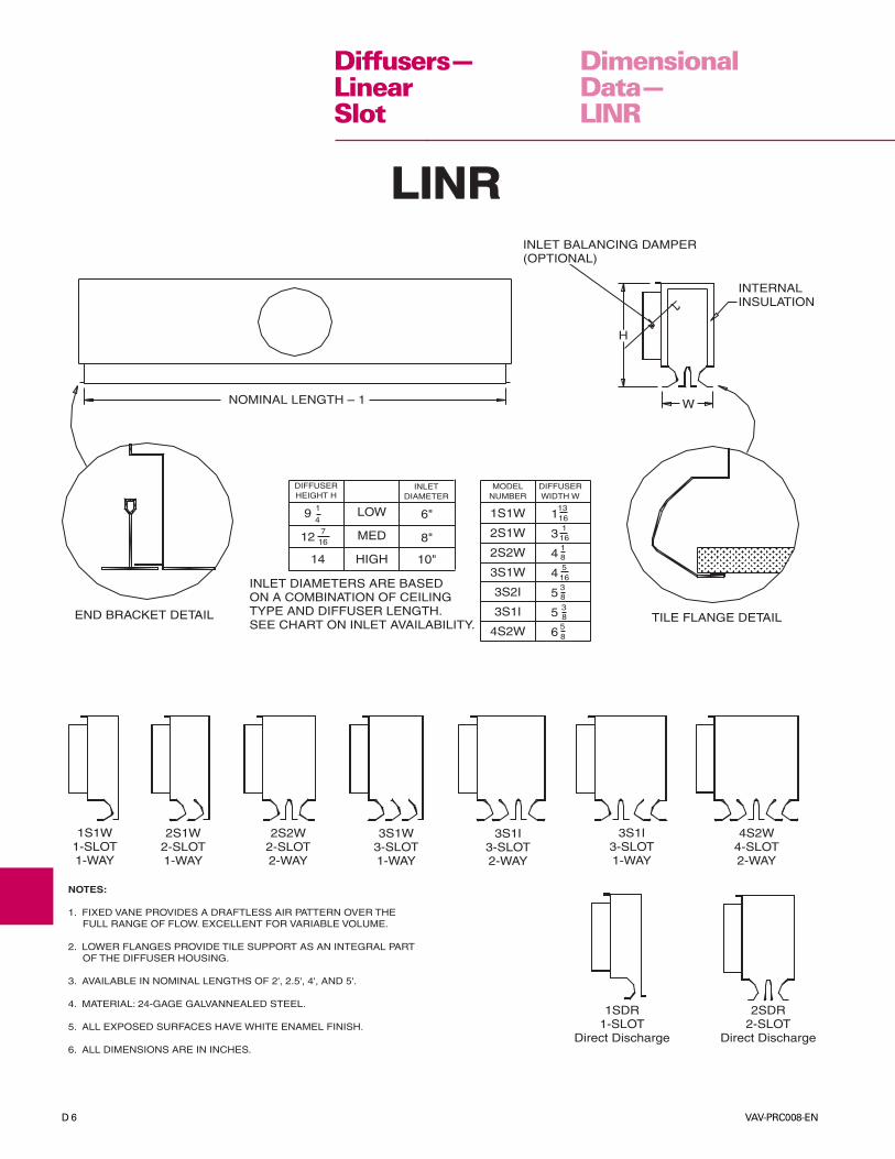
Linear Slot DiffusersThe features of the Linear Slot Diffuserare described by the productcategories shown in bold. Within eachcategory the options available arelisted.
MODL ModelVLSD Supply DiffuserVLRD Return Slot
DSEQ Design SequenceA A Design Sequence
TYPE Diffuser TypeLINR Linear Diffuser
LGTH Diffuser Length2 Diffuser Length – 2'2.5 Diffuser Length – 2 1/2'4 Diffuser Length – 4'5 Diffuser Length – 5'
HGTH Diffuser HeightLOW Low HeightMED Medium HeightHIGH High HeightNONE For Return Slots
WDTH Ceiling Tee Width916 9/16" Ceiling Grid1516 15/16" Ceiling Grid
SLOT Slot Configuration1S1W 1-Slot, 1-Way2S1W 2-Slot, 1-Way3S1W 3-Slot, 1-Way2S2W 2-Slot, 2-Way4S2W 4-Slot, 2-Way1SDR 1-Slot, Direct Discharge3S1I 3-Slot, 2 Way, Inlet on 1-Slot Side3S2I 3-Slot, 2 Way, Inlet on 2-Slot Side2SDR 2-Slot, Direct Discharge
CEIL Ceiling TypeTBAR 15/16" T-Bar2X2T 15/16" T-Bar with Center NotchPLSR Plaster CeilingT916 9/16" Narrow Faced GridD916 9/16" Narrow Regressed Grid2X2N 9/16" Center Notch, Narrow
Faced Grid2X2D 9/16" Center Notch, Narrow
Regressed GridSPLN Concealed Spline
DMPR Damper TypeFIRE Fire DamperBAL Balancing Damper
HNGR Hanger HolesWITH Hanger Holes
INLET DIAMETERS ARE BASEDON A COMBINATION OF CEILINGTYPE AND DIFFUSER LENGTH.SEE CHART ON INLET AVAILABILITY.
LINRLINRINLET BALANCING DAMPER(OPTIONAL)
INTERNALINSULATION
H
W
TILE FLANGE DETAIL
NOMINAL LENGTH – 1
END BRACKET DETAIL
1S1W1-SLOT1-WAY
3S1W3-SLOT1-WAY
4S2W4-SLOT2-WAY
3S1I3-SLOT1-WAY
3S1I3-SLOT2-WAY
1SDR1-SLOT
Direct Discharge
2S2W2-SLOT2-WAY
2S1W2-SLOT1-WAY
2SDR2-SLOT
Direct Discharge
NOTES:
1. FIXED VANE PROVIDES A DRAFTLESS AIR PATTERN OVER THE FULL RANGE OF FLOW. EXCELLENT FOR VARIABLE VOLUME.
2. LOWER FLANGES PROVIDE TILE SUPPORT AS AN INTEGRAL PART OF THE DIFFUSER HOUSING.
3. AVAILABLE IN NOMINAL LENGTHS OF 2', 2.5', 4', AND 5'.
4. MATERIAL: 24-GAGE GALVANNEALED STEEL.
5. ALL EXPOSED SURFACES HAVE WHITE ENAMEL FINISH.
6. ALL DIMENSIONS ARE IN INCHES.
MODELNUMBER
DIFFUSERWIDTH W
1S1W
2S1W
2S2W
3S1W
3S2I
3S1I
4S2W
1
3
4
4
5
5
6
13
16
16
5
3
3
1
1
5
16
8
8
8
8
DIFFUSERHEIGHT H
LOW
MED
HIGH
9
12
1
7
4
16
14
INLETDIAMETER
6"
8"
10"
ModelNumberDescription
Diffusers—LinearSlot
VAV-PRC008-EN D 5
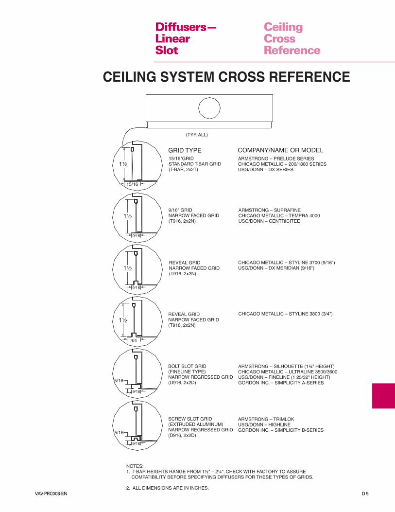
GRID TYPE COMPANY/NAME OR MODEL15/16"GRIDSTANDARD T-BAR GRID(T-BAR, 2x2T)
ARMSTRONG – PRELUDE SERIESCHICAGO METALLIC – 200/1800 SERIESUSG/DONN – DX SERIES
9/16" GRIDNARROW FACED GRID(T916, 2x2N)
ARMSTRONG – SUPRAFINECHICAGO METALLIC – TEMPRA 4000USG/DONN – CENTRICITEE
REVEAL GRIDNARROW FACED GRID(T916, 2x2N)
CHICAGO METALLIC – STYLINE 3700 (9/16")USG/DONN – DX MERIDIAN (9/16")
REVEAL GRIDNARROW FACED GRID(T916, 2x2N)
CHICAGO METALLIC – STYLINE 3800 (3/4")
BOLT SLOT GRID(FINELINE TYPE)NARROW REGRESSED GRID(D916, 2x2D)
ARMSTRONG – SILHOUETTE (1¾" HEIGHT)CHICAGO METALLIC – ULTRALINE 3500/3600USG/DONN – FINELINE (1 25/32" HEIGHT)GORDON INC. – SIMPLICITY A-SERIES
SCREW SLOT GRID(EXTRUDED ALUMINUM)NARROW REGRESSED GRID(D916, 2x2D)
ARMSTRONG – TRIMLOKUSG/DONN – HIGHLINEGORDON INC. – SIMPLICITY B-SERIES
NOTES:1. T-BAR HEIGHTS RANGE FROM 1½" – 2¼". CHECK WITH FACTORY TO ASSURE COMPATIBILITY BEFORE SPECIFYING DIFFUSERS FOR THESE TYPES OF GRIDS.
2. ALL DIMENSIONS ARE IN INCHES.
9/16
15/16
5/16
5/16
9/16
9/16
9/16
3/4
1½
1½
1½
1½
(TYP. ALL)
CEILING SYSTEM CROSS REFERENCE
CeilingCrossReference
Diffusers—LinearSlot
D 6 VAV-PRC008-EN
DimensionalData—LINR
INLET DIAMETERS ARE BASEDON A COMBINATION OF CEILINGTYPE AND DIFFUSER LENGTH.SEE CHART ON INLET AVAILABILITY.
LINRLINRINLET BALANCING DAMPER(OPTIONAL)
INTERNALINSULATION
H
W
TILE FLANGE DETAIL
NOMINAL LENGTH – 1
END BRACKET DETAIL
1S1W1-SLOT1-WAY
3S1W3-SLOT1-WAY
4S2W4-SLOT2-WAY
3S1I3-SLOT1-WAY
3S1I3-SLOT2-WAY
1SDR1-SLOT
Direct Discharge
2S2W2-SLOT2-WAY
2S1W2-SLOT1-WAY
2SDR2-SLOT
Direct Discharge
NOTES:
1. FIXED VANE PROVIDES A DRAFTLESS AIR PATTERN OVER THE FULL RANGE OF FLOW. EXCELLENT FOR VARIABLE VOLUME.
2. LOWER FLANGES PROVIDE TILE SUPPORT AS AN INTEGRAL PART OF THE DIFFUSER HOUSING.
3. AVAILABLE IN NOMINAL LENGTHS OF 2', 2.5', 4', AND 5'.
4. MATERIAL: 24-GAGE GALVANNEALED STEEL.
5. ALL EXPOSED SURFACES HAVE WHITE ENAMEL FINISH.
6. ALL DIMENSIONS ARE IN INCHES.
MODELNUMBER
DIFFUSERWIDTH W
1S1W
2S1W
2S2W
3S1W
3S2I
3S1I
4S2W
1
3
4
4
5
5
6
13
16
16
5
3
3
1
1
5
16
8
8
8
8
DIFFUSERHEIGHT H
LOW
MED
HIGH
9
12
1
7
4
16
14
INLETDIAMETER
6"
8"
10"
Diffusers—LinearSlot
VAV-PRC008-EN D 7
DimensionalData—LINR
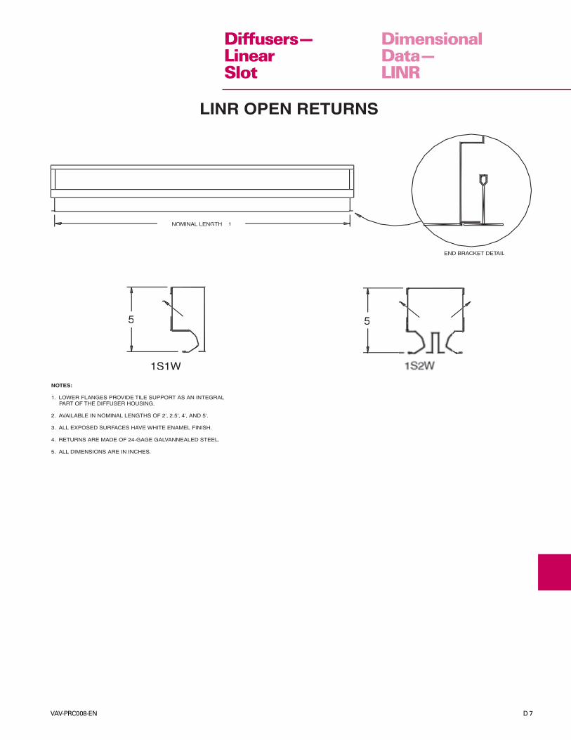
LINR OPEN RETURNSLINR OPEN RETURNS
NOMINAL LENGTH – 1
END BRACKET DETAIL
5555
1S1W
NOTES:
1. LOWER FLANGES PROVIDE TILE SUPPORT AS AN INTEGRAL PART OF THE DIFFUSER HOUSING.
2. AVAILABLE IN NOMINAL LENGTHS OF 2', 2.5', 4', AND 5'.
3. ALL EXPOSED SURFACES HAVE WHITE ENAMEL FINISH.
4. RETURNS ARE MADE OF 24-GAGE GALVANNEALED STEEL.
5. ALL DIMENSIONS ARE IN INCHES.
Diffusers—LinearSlot
D 8 VAV-PRC008-EN
DimensionalData—LINR
2. This drawing is for pictorial view only and not to be usedfor dimensional purposes.
158˚F (70˚C) fusible links.1. Spring loaded dampers blades are hinged and held open by
Notes:
U.L. Listed
Fire Damper20-gage Steel
Fusible Link
ONE WAY LINEAR SLOT DIFFUSER OR RETURN SLOT
TWO WAY LINEAR SLOT DIFFUSER OR RETURN SLOT
3. The UL Reference R6700 VOLUME 2 (1-SLOT and 2-SLOT models only).
Fusible Link
Fire Damper20-gage Steel
U.L. Listed
1-WAY1-SLOT
1-WAY2-SLOT
1S1W 2S1W 3S1W
1-WAY3-SLOT
3S2I3-SLOT2-WAY
3S1I
1-WAY3-SLOT 3-SLOT
1-WAY
3S1I
2-WAY2-SLOT2S2W
4-SLOT2-WAY
4S2W
Diffusers—LinearSlot

VAV-PRC008-EN D 9
DimensionalData—LINR
Diffusers—LinearSlot
SLOT DIFFUSER SURFACE MOUNT FRAMESFOR PLASTER CEILING
ACTUALDIFFUSER + 1LENGTH
3
WDIFFUSER WIDTH
CLIP
¾¾
DIFFUSER
CEILINGFRAME
SECTION DETAIL(INSTALLED)
MODELNUMBER
DIFFUSER
1S1W
2S2W
3S1W
3S1I
3S2I
4S2W
D 10 VAV-PRC008-EN
InletAvailability
Diffusers—LinearSlot
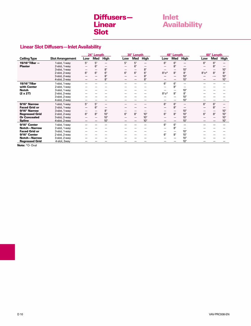
Linear Slot Diffusers—Inlet Availability
24" Length 30" Length 48" Length 60" LengthCeiling Type Slot Arrangement Low Med High Low Med High Low Med High Low Med High
15/16" T-Bar — 1-slot, 1-way 5" 5" — 5" 5" — 6" 6" — 6" 6" —Plaster 2-slot, 1-way — 6" — — 6" — — 8" — — 8" —
3-slot, 1-way — — 8" — — 8" — — 10" — — 10"2-slot, 2-way 6" 6" 6" 6" 6" 6" 8"o* 8" 8" 8"o* 8" 8"3-slot, 2-way — — 8" — — 8" — — 10" — -— 10"4-slot, 2-way — — 8" — — 8" — — 10" — — 10"
15/16" T-Bar 1-slot, 1-way — — — — — — 6" 6" — — — —with Center 2-slot, 1-way — — — — — — — 8" — — — —Notch 3-slot, 1-way — — — — — — — — 10" — — —(2 x 2 T) 2-slot, 2-way — — — — — — 8"o* 8" 8" — — —
3-slot, 2-way — — — — — — — — 10" — — —4-slot, 2-way — — — — — — — — 10" — — —
9/16" Narrow 1-slot, 1-way 5" 5" — — — — 6" 6" — 6" 6" —Faced Grid or 2-slot, 1-way — 6" — — — — — 8" — — 8" —9/16" Narrow 3-slot, 1-way — — 8" — — — — — 10" — — 10"Regressed Grid 2-slot, 2-way 6" 8" 10" 6" 8" 10" 6" 8" 10" 6" 8" 10"Or Concealed 3-slot, 2-way — — 10" — — 10" — — 10" — — 10"Spline 4-slot, 2-way — — 10" — — 10" — — 10" — — 10"9/16" Center 1-slot, 1-way — — — — — — 6" 6" — — — —Notch—Narrow 2-slot, 1-way — — — — — — — 8" — — — —Faced Grid or 3-slot, 1-way — — — — — — — — 10" — — —9/16" Center 2-slot, 2-way — — — — — — 6" 8" 10" — — —Notch—Narrow 3-slot, 2-way — — — — — — — — 10" — — —Regressed Grid 4-slot, 2way — — — — — — — — 10" — — —
Note: *O- Oval
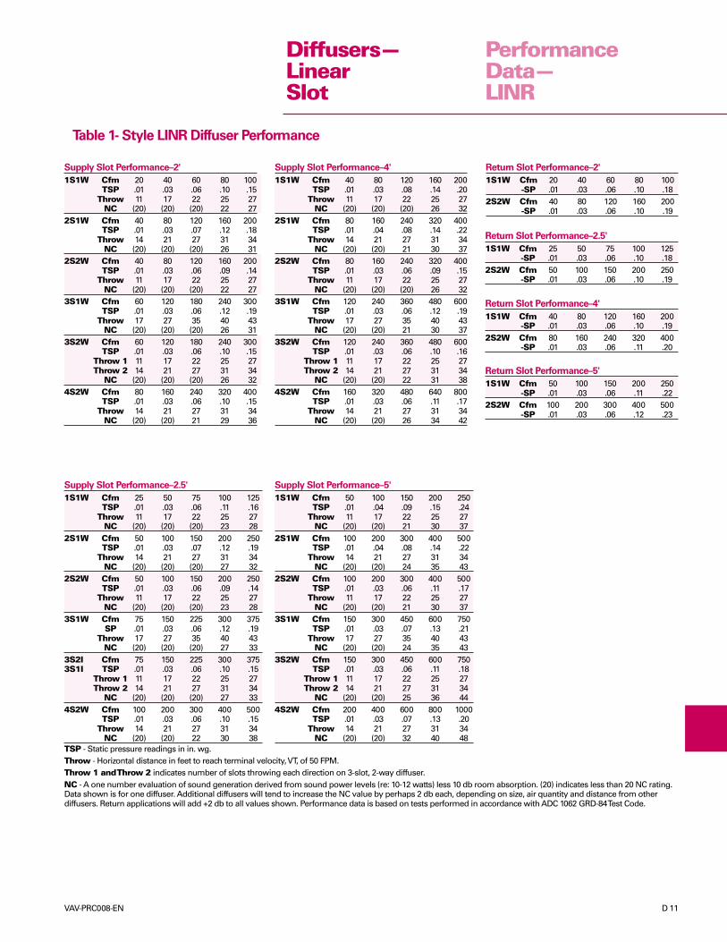
VAV-PRC008-EN D 11
PerformanceData—LINR
TSP - Static pressure readings in in. wg.Throw - Horizontal distance in feet to reach terminal velocity, VT, of 50 FPM.Throw 1 and Throw 2 indicates number of slots throwing each direction on 3-slot, 2-way diffuser.NC - A one number evaluation of sound generation derived from sound power levels (re: 10-12 watts) less 10 db room absorption. (20) indicates less than 20 NC rating.Data shown is for one diffuser. Additional diffusers will tend to increase the NC value by perhaps 2 db each, depending on size, air quantity and distance from otherdiffusers. Return applications will add +2 db to all values shown. Performance data is based on tests performed in accordance with ADC 1062 GRD-84 Test Code.
Diffusers—LinearSlot
Supply Slot Performance–5'
1S1W Cfm 50 100 150 200 250TSP .01 .04 .09 .15 .24
Throw 11 17 22 25 27NC (20) (20) 21 30 37
2S1W Cfm 100 200 300 400 500TSP .01 .04 .08 .14 .22
Throw 14 21 27 31 34NC (20) (20) 24 35 43
2S2W Cfm 100 200 300 400 500TSP .01 .03 .06 .11 .17
Throw 11 17 22 25 27NC (20) (20) 21 30 37
3S1W Cfm 150 300 450 600 750TSP .01 .03 .07 .13 .21
Throw 17 27 35 40 43NC (20) (20) 24 35 43
3S2W Cfm 150 300 450 600 750TSP .01 .03 .06 .11 .18
Throw 1 11 17 22 25 27Throw 2 14 21 27 31 34
NC (20) (20) 25 36 444S2W Cfm 200 400 600 800 1000
TSP .01 .03 .07 .13 .20Throw 14 21 27 31 34
NC (20) (20) 32 40 48
Supply Slot Performance–2.5'
1S1W Cfm 25 50 75 100 125TSP .01 .03 .06 .11 .16
Throw 11 17 22 25 27NC (20) (20) (20) 23 28
2S1W Cfm 50 100 150 200 250TSP .01 .03 .07 .12 .19
Throw 14 21 27 31 34NC (20) (20) (20) 27 32
2S2W Cfm 50 100 150 200 250TSP .01 .03 .06 .09 .14
Throw 11 17 22 25 27NC (20) (20) (20) 23 28
3S1W Cfm 75 150 225 300 375SP .01 .03 .06 .12 .19
Throw 17 27 35 40 43NC (20) (20) (20) 27 33
3S2I Cfm 75 150 225 300 3753S1I TSP .01 .03 .06 .10 .15
Throw 1 11 17 22 25 27Throw 2 14 21 27 31 34
NC (20) (20) (20) 27 334S2W Cfm 100 200 300 400 500
TSP .01 .03 .06 .10 .15Throw 14 21 27 31 34
NC (20) (20) 22 30 38
Table 1- Style LINR Diffuser Performance
Supply Slot Performance–4'
1S1W Cfm 40 80 120 160 200TSP .01 .03 .08 .14 .20
Throw 11 17 22 25 27NC (20) (20) (20) 26 32
2S1W Cfm 80 160 240 320 400TSP .01 .04 .08 .14 .22
Throw 14 21 27 31 34NC (20) (20) 21 30 37
2S2W Cfm 80 160 240 320 400TSP .01 .03 .06 .09 .15
Throw 11 17 22 25 27NC (20) (20) (20) 26 32
3S1W Cfm 120 240 360 480 600TSP .01 .03 .06 .12 .19
Throw 17 27 35 40 43NC (20) (20) 21 30 37
3S2W Cfm 120 240 360 480 600TSP .01 .03 .06 .10 .16
Throw 1 11 17 22 25 27Throw 2 14 21 27 31 34
NC (20) (20) 22 31 384S2W Cfm 160 320 480 640 800
TSP .01 .03 .06 .11 .17Throw 14 21 27 31 34
NC (20) (20) 26 34 42
Return Slot Performance–2'
1S1W Cfm 20 40 60 80 100-SP .01 .03 .06 .10 .18
2S2W Cfm 40 80 120 160 200-SP .01 .03 .06 .10 .19
Return Slot Performance–2.5'
1S1W Cfm 25 50 75 100 125-SP .01 .03 .06 .10 .18
2S2W Cfm 50 100 150 200 250-SP .01 .03 .06 .10 .19
Return Slot Performance–4'
1S1W Cfm 40 80 120 160 200-SP .01 .03 .06 .10 .19
2S2W Cfm 80 160 240 320 400-SP .01 .03 .06 .11 .20
Return Slot Performance–5'
1S1W Cfm 50 100 150 200 250-SP .01 .03 .06 .11 .22
2S2W Cfm 100 200 300 400 500-SP .01 .03 .06 .12 .23
Supply Slot Performance–2'
1S1W Cfm 20 40 60 80 100TSP .01 .03 .06 .10 .15
Throw 11 17 22 25 27NC (20) (20) (20) 22 27
2S1W Cfm 40 80 120 160 200TSP .01 .03 .07 .12 .18
Throw 14 21 27 31 34NC (20) (20) (20) 26 31
2S2W Cfm 40 80 120 160 200TSP .01 .03 .06 .09 .14
Throw 11 17 22 25 27NC (20) (20) (20) 22 27
3S1W Cfm 60 120 180 240 300TSP .01 .03 .06 .12 .19
Throw 17 27 35 40 43NC (20) (20) (20) 26 31
3S2W Cfm 60 120 180 240 300TSP .01 .03 .06 .10 .15
Throw 1 11 17 22 25 27Throw 2 14 21 27 31 34
NC (20) (20) (20) 26 324S2W Cfm 80 160 240 320 400
TSP .01 .03 .06 .10 .15Throw 14 21 27 31 34
NC (20) (20) 21 29 36
D 12 VAV-PRC008-EN
ModelNumberDescription
STYL Diffuser StyleNONE For VAPF, AABD, and VAPS11 1-slot – one way12 1-slot – 2-way left or right13 1-slot – 1-way with 1
factory-installed T-bar14 1-slot – 2-way left or right
with 1 factory-installed T-bar15 1-slot – 1-way with 2
factory-installed T-bars16 1-slot – 2-way left or right
with 2 factory-installed T-bars21 2-slot – 2-way opposite22 2-slot – 2-way opposite left
or right23 2-slot – 2-way opposite
with 1 factory-installed T-bar24 2-slot – 2-way opposite left
or right with 1 factory-installedT-bar
25 2-slot – 2-way oppositewith 2 factory-installed T-bars
26 2-slot – 2-way opposite leftor right with 2 factory-installedT-bars
27 2-slot – 2-way opposite with3 factory-installed T-bars
28 2-slot – 2-way opposite leftor right with 3 factory-installedT-bars
29 2-slot – 2-way opposite with2 factory-installed T-bars
33 3-slot – 1-way34 3-slot – 2-way left or right43 1-slot – 2-way opposite44 4-slot – 2-way opposite left
or right
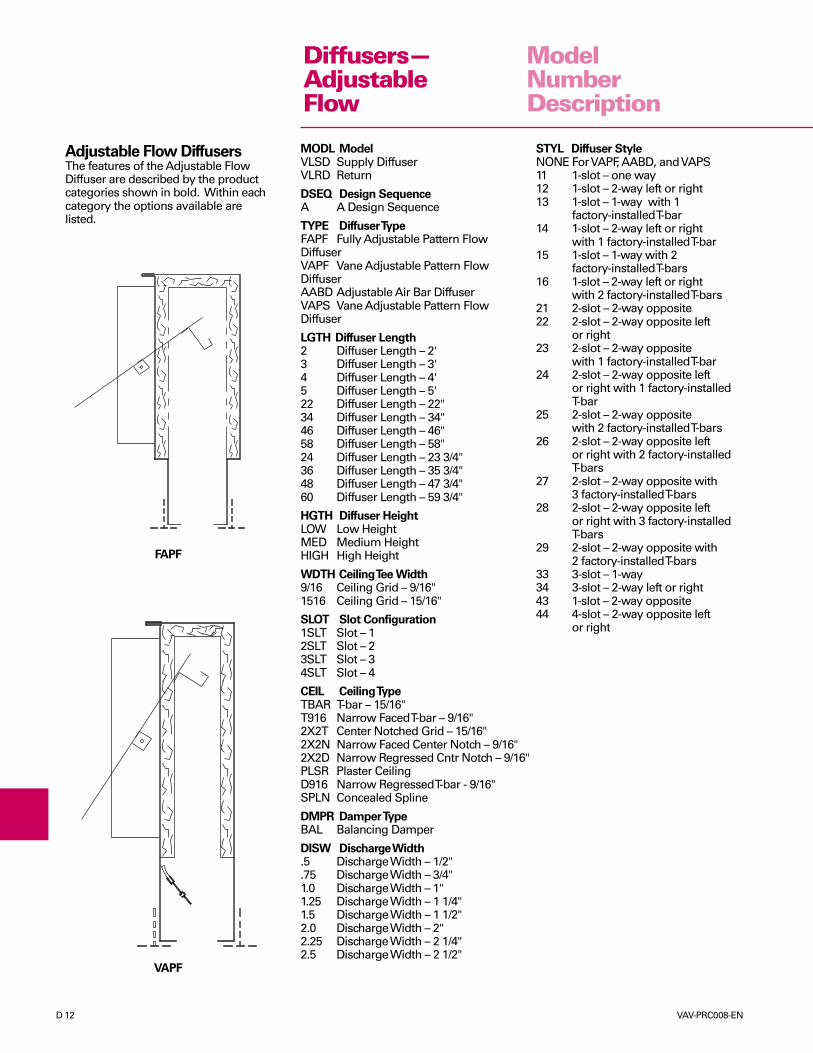
Adjustable Flow DiffusersThe features of the Adjustable FlowDiffuser are described by the productcategories shown in bold. Within eachcategory the options available arelisted.
MODL ModelVLSD Supply DiffuserVLRD Return
DSEQ Design SequenceA A Design Sequence
TYPE Diffuser TypeFAPF Fully Adjustable Pattern FlowDiffuserVAPF Vane Adjustable Pattern FlowDiffuserAABD Adjustable Air Bar DiffuserVAPS Vane Adjustable Pattern FlowDiffuser
LGTH Diffuser Length2 Diffuser Length – 2'3 Diffuser Length – 3'4 Diffuser Length – 4'5 Diffuser Length – 5'22 Diffuser Length – 22"34 Diffuser Length – 34"46 Diffuser Length – 46"58 Diffuser Length – 58"24 Diffuser Length – 23 3/4"36 Diffuser Length – 35 3/4"48 Diffuser Length – 47 3/4"60 Diffuser Length – 59 3/4"
HGTH Diffuser HeightLOW Low HeightMED Medium HeightHIGH High Height
WDTH Ceiling Tee Width9/16 Ceiling Grid – 9/16"1516 Ceiling Grid – 15/16"
SLOT Slot Configuration1SLT Slot – 12SLT Slot – 23SLT Slot – 34SLT Slot – 4
CEIL Ceiling TypeTBAR T-bar – 15/16"T916 Narrow Faced T-bar – 9/16"2X2T Center Notched Grid – 15/16"2X2N Narrow Faced Center Notch – 9/16"2X2D Narrow Regressed Cntr Notch – 9/16"PLSR Plaster CeilingD916 Narrow Regressed T-bar - 9/16"SPLN Concealed Spline
DMPR Damper TypeBAL Balancing Damper
DISW Discharge Width.5 Discharge Width – 1/2".75 Discharge Width – 3/4"1.0 Discharge Width – 1"1.25 Discharge Width – 1 1/4"1.5 Discharge Width – 1 1/2"2.0 Discharge Width – 2"2.25 Discharge Width – 2 1/4"2.5 Discharge Width – 2 1/2"
VAPF
FAPF
Diffusers—AdjustableFlow

VAV-PRC008-EN D 13
INLETDIAMETER HEIGHT
6"
8"
10"
LOW - 9"
MED - 11"
HIGH - 13"
VAPF
INLETINLETDIA +3DIA +3
NOMINAL LENGTH - ¼
NOMINAL LENGTH
½ INTERNAL INSULATIONINLET DAMPER (OPTIONAL)
916
A
B
99 9161616 AAA
BBB
CENTER T - BARSTANDARD ON 2, 3, 4 SLOT
T - BAR CLIPS(OPTIONAL)
SIDE T - BARS(OPTIONAL)
SLOTWIDTH A
DIFFUSER WIDTH B
1-SLOT 2-SLOT 3-SLOT 4-SLOT3"4
1
1"
11"2
7"81"82
2
3
4
5
5
6
7
7"
8"
10"5"8
5"81"81"8
5"161"169"16
NOTES:
1. MATERIAL: 24-GAGE GALVANNEALED STEEL. ALL EXPOSED SURFACES PAINTED FLAT BLACK. T - BARS ARE WHITE.
2. AVAILABLE IN NOMINAL LENGTHS OF 2', 3', 4', & 5'.
3. ALUMINUM VANE WITH FELT SEAL IS FULLY ADJUSTABLE FROM THE FACE FOR LEFT, RIGHT, OR VERTICAL THROW.
4. DESIGNED FOR VARIABLE OR CONSTANT VOLUME SYSTEMS.
5. MAXIMUM PERFORMANCE AND FLEXIBILITY FOR INTERIOR OR PERIMETER APPLICATIONS IN A VARIETY OF CEILING SYSTEMS.
6. ALL DIMENSIONS ARE IN INCHES
DimensionalData—VAPF
Diffusers—AdjustableFlow

D 14 VAV-PRC008-EN
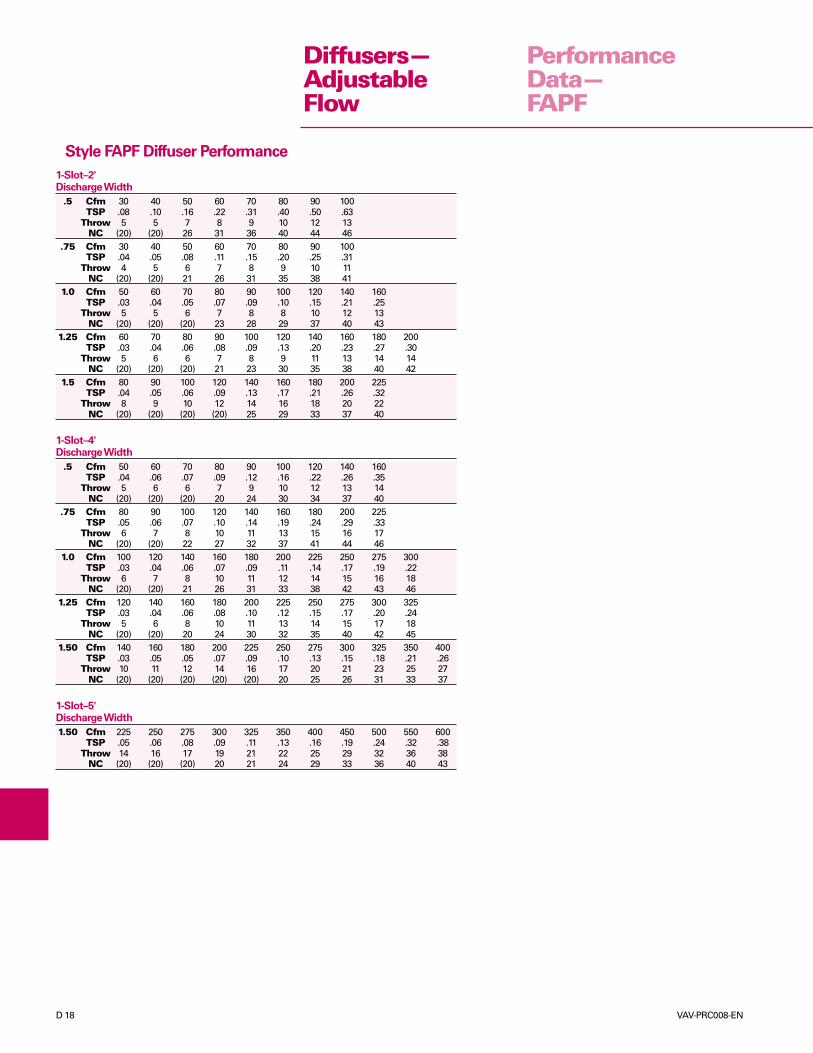
Style VAPF Diffuser Performance
PerformanceData—VAPF
Diffusers—AdjustableFlow
2-Slot–5'Discharge Width
.75 Cfm 75 125 200 250 300 375(Ak .24) TSP .01 .02 .06 .10 .14 .22(High) Throw 7 13 20 26 29 32
NC (20) (20) (20) 26 31 381.0 Cfm 150 200 250 300 400 500
(Ak .28) TSP .03 .05 .07 .10 .18 .29(High) Throw 14 20 27 29 32 34
NC (20) (20) 20 25 33 38
3-Slot–2'Discharge Width
.75 Cfm 50 75 125 175 225 250(Ak .14) TSP .01 .02 .07 .13 .21 .26(Med) Throw 7 11 19 22 26 28
NC (20) (20) (20) 28 35 391.0 Cfm 75 100 150 175 225 300
(Ak .17) TSP .02 .03 .07 .10 .16 .28(Med) Throw 10 15 22 23 26 30
NC (20) (20) (20) 22 29 361.5 Cfm 75 125 200 250 300 375
(Ak .33) TSP .01 .02 .04 .06 .09 .14(High) Throw 5 12 20 26 29 32
NC (20) (20) (20) 21 25 31
3-Slot–4'Discharge Width
.75 Cfm 75 150 225 300 375 450(Ak .29) TSP .01 .03 .06 .10 .16 .23(High) Throw 6 17 26 30 33 37
NC (20) (20) (20) 27 33 381.0 Cfm 150 225 300 400 500 600
(Ak .34) TSP .02 .04 .08 .14 .22 .31(High) Throw 16 23 31 34 39 43
NC (20) (20) 21 29 34 39
4-Slot–2'Discharge Width
.75 Cfm 50 100 150 200 250 300(Ak .19) TSP .01 .03 .06 .10 .16 .24(Med) Throw 5 14 20 24 28 30
NC (20) (20) (20) 25 31 371.0 Cfm 100 150 200 250 300 400
(Ak .22) TSP .02 .05 .08 .12 .18 .32(Med) Throw 13 19 26 28 30 34
NC (20) (20) (20) 25 30 371.5 Cfm 75 150 225 300 375 450
(Ak .44) TSP .01 .02 .03 .06 .09 .13(High) Throw 3 13 19 27 33 35
NC (20) (20) (20) (20) 25 30
4-Slot–4'Discharge Width
.75 Cfm 100 200 300 400 500 600(Ak .39) TSP .01 .03 .06 .10 .16 .22(High) Throw 7 19 29 34 39 43
NC (20) (20) (20) 28 34 40TSP - Total pressure readings in in. wg with horizontal throw.Ak - Area factor along with cfm is used to determine theaverage face velocity - Vk = cfm / AkThrow - Horizontal distance in feet to reach terminal velocity,VT, of 50 FPM.NC - A one number evaluation of sound generation derivedfrom sound power levels ( re: 10-12 watts) less 10 db roomabsorption. (20) indicates less than 20 NC rating. Data shown isfor one diffuser. Additional diffusers will tend to increase theNC value by perhaps 2 db each, depending on size, air quantityand distance from other diffusers. Return applications will add+2 db to all values shown. Peformance data is based on testsperformed in accordance with ADC 1062 GRD-84 Test Code.
1-Slot–2'Discharge Width
.75 Cfm 15 25 35 50 75 100(Ak .05) TSP .01 .02 .04 .09 .20 .35(Low) Throw 5 7 9 11 15 17
NC (20) (20) (20) (20) 31 391.0 Cfm 20 35 50 75 100 125
(Ak .06) TSP .01 .03 .06 .14 .25 .39(Low) Throw 5 8 13 15 17 19
NC (20) (20) (20) 24 31 371.5 Cfm 25 50 85 100 125 175
(Ak .11) TSP .01 .02 .05 .08 .13 .26(Med) Throw 3 9 13 17 19 24
NC (20) (20) (20) 21 26 35
1-Slot–4'Discharge Width
.75 Cfm 25 50 75 100 125 175(Ak .10) TSP .01 .03 .06 .10 .16 .32(Low) Throw 4 10 14 17 19 22
NC (20) (20) (20) 22 28 381.0 Cfm 50 75 100 150 200 250
(Ak .11) TSP .02 .04 .06 .14 .26 .40(Med) Throw 8 13 18 21 23 27
NC (20) (20) (20) 27 34 401.5 Cfm 50 100 150 200 250 300
(Ak .22) TSP .01 .02 .05 .09 .14 .20(Med) Throw 4 11 17 22 25 28
NC (20) (20) (20) 24 29 34
1-Slot–5'Discharge Width
.75 Cfm 50 75 100 125 150 200(Ak .12) TSP .02 .03 .06 .09 .13 .23(Med) Throw 8 12 17 19 22 24
NC (20) (20) (20) 23 28 371.0 Cfm 75 100 150 200 250 300
(Ak .14) TSP .02 .04 .09 .16 .25 .36(High) Throw 9 14 20 24 27 28
NC (20) (20) 22 30 35 401.5 Cfm 75 125 200 250 300 350
(Ak .28) TSP .01 .02 .05 .08 .12 .16(High) Throw 7 13 20 26 29 31
NC (20) (20) (20) 25 29 33
2-Slot–2'Discharge Width
.75 Cfm 25 50 75 100 125 150(Ak .10) TSP .01 .03 .06 .10 .16 .22(Low) Throw 4 10 14 17 20 24
NC (20) (20) (20) 22 28 341.0 Cfm 50 75 100 125 150 200
(Ak .11) TSP .02 .04 .08 .12 .17 .30(Low) Throw 9 13 18 19 22 25
NC (20) (20) (20) 22 27 341.5 Cfm 50 100 150 200 250 300
(Ak .22) TSP .01 .02 .05 .09 .14 .20(Med) Throw 6 12 19 23 27 30
NC (20) (20) (20) 24 29 34
2-Slot–4'Discharge Width
.75 Cfm 50 100 150 200 250 300(Ak .19) TSP .01 .03 .06 .10 .16 .23(Med) Throw 6 13 19 24 27 30
NC (20) (20) (20) 25 31 371.0 Cfm 100 150 200 250 300 400
(Ak .22) TSP .02 .05 .08 .12 .18 .32(Med) Throw 11 16 21 26 28 33
NC (20) (20) (20) 25 30 37

VAV-PRC008-EN D 15
DimensionalData—VAPS
VAPS
controller throughout the range of settings including vertical.
1. Material: 24-gage galvannealed steel with exposed surfaces andpattern controller painted flat black.
2. Neck opening is located so that the bottom of inlet is above air pattern
Notes:
LENGTH
Length
10" OVAL8"
6"7"
10" OVAL8"
6"7"
INLET
3
Open Return
1316
161
2
163
13
1 316
Supply Diffuser
161
2
16
1613
3
13
7
78
81
1
InletDiameter
21
12
60" (59-3/4")48" (47-3/4")
36" (35-3/4")24" (23-3/4")
58463422
"""
"
"
"
"
"
"
"
Inlet Damper (Optional)
notched grid ceilings.3. VAPS diffusers are only available for 15/16" T-Bar and 15/16" center
Insulation
4. All dimensions are in inches.
"
"
"
"
"
"
Diffusers—AdjustableFlow
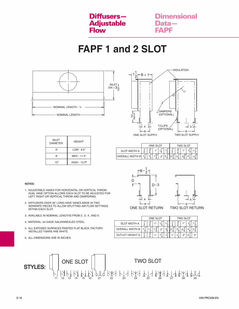
D 16 VAV-PRC008-EN
DimensionalData—FAPF
23"
4 44
3+
B
12
2
34
1
FAPF 1 and 2 SLOT
STYLES:STYLES:ONE SLOT
11 12 13 14 15 16 21 22 23 24 25 26 27 28 29
TWO SLOT
ONE SLOT RETURN TWO SLOT RETURN
ONE SLOT TWO SLOT
SLOT WIDTH A
OVERALL WIDTH B
OUTLET HEIGHT D 1"
1" 1
11"
1"1"
1"1
1" 1"
1
1 1
1"1"
1"1
1"
1"
1"1
1"
1"1"
1"
1"
1
2 22
2
2
2
2 21"1 2"
2" 2
3
3"
3"
3"
3"
3"
3"
3"33 4
4
4
4
4 4
4
4
4
2
4 54
4
12
DD
+
BB
A A
INLETDIAMETER
21 B + 1
INSULATION
A
B
122
A
B
T-CLIPS(OPTIONAL)
DAMPERS(OPTIONAL)
NOMINAL LENGTH - ¼
NOMINAL LENGTH
1
HEIGHT
6"
8"
10"
LOW - 9.5"
MED - 11.5"
HIGH - 13.5""
SLOT WIDTH A
OVERALL WIDTH B
ONE SLOT SUPPLY
ONE SLOT
TWO SLOT SUPPLY
TWO SLOT1"
1"
1"1"1"
1"
1"
1"
1"1"1"
1"1"2 2"
2 2
2
23"
3" 3 3"
3"
3 3" 3"4 4
44
4
4 4
4 44
4 41 1 1
1 1 1
5
NOTES:
1. ADJUSTABLE VANES FOR HORIZONTAL OR VERTICAL THROW. DUAL VANE OPTION ALLOWS EACH SLOT TO BE ADJUSTED FOR LEFT, RIGHT OR VERTICAL THROW AND DAMPERING.
2. DIFFUSERS OVER 36" LONG HAVE VANES MADE IN TWO SEPARATE PIECES TO ALLOW SPLITTING AIR FLOW SETTINGS WITHIN EACH SLOT.
3. AVAILABLE IN NOMINAL LENGTHS FROM 2', 3', 4', AND 5'.
4. MATERIAL: 24-GAGE GALVANNEALED STEEL.
5. ALL EXPOSED SURFACES PAINTED FLAT BLACK. FACTORY- INSTALLED T-BARS ARE WHITE.
6. ALL DIMENSIONS ARE IN INCHES.
INLETDIA +3
Diffusers—AdjustableFlow
VAV-PRC008-EN D 17
DimensionalData—FAPF
PATTERN CONFIGURATIONS
NOTES:
1. AVAILABLE IN NOMINAL LENGTHS FROM 2 TO 5 FEET.
2. MATERIAL: 24-GAGE GALVANNEALED STEEL.
3. ALL EXPOSED SURFACES PAINTED FLAT BLACK. FACTORY-INSTALLED T-BARS ARE WHITE.
4. ALL DIMENSIONS ARE IN INCHES.
SINGLE VANES ALLOW EACH SLOT TOTHROW IN ONE HORIZONTAL DIRECTIONOR VERTICAL. SPECIFY THE NUMBER OFSLOTS TO THROW IN EACH DIRECTION.EX:
DUAL VANES ALLOW EACH SLOT TO BEADJUSTED FOR RIGHT, LEFT OR VERTICALTHROW. (STYL 34)
(STYL 43)(STYL 33)
(STYL 44)
THREE SLOT FOUR SLOT
SIDE T-BARS(OPTIONAL)
CENTER T-BARS(STANDARD)
SLOTWIDTH A
OVERALLWIDTH B
3"
3"
3"3"1" 11"11"
4 4 4
4
215" 11" 5"5"5"516 1616
7 6 978 88
A
B
INLETDIA + 3½
2½ ½
INLET DAMPER(OPTIONAL)
INSULATION
FAPF 3 and 4 SLOT
NOMINAL LENGTH - ¼
INLETDIAMETER
HEIGHT
6"
8"
10"
LOW - 9.5"
MED - 11.5"
HIGH - 13.5"
Diffusers—AdjustableFlow
D 18 VAV-PRC008-EN
PerformanceData—FAPF
Diffusers—AdjustableFlow
1-Slot–2'Discharge Width
.5 Cfm 30 40 50 60 70 80 90 100TSP .08 .10 .16 .22 .31 .40 .50 .63
Throw 5 5 7 8 9 10 12 13NC (20) (20) 26 31 36 40 44 46
.75 Cfm 30 40 50 60 70 80 90 100TSP .04 .05 .08 .11 .15 .20 .25 .31
Throw 4 5 6 7 8 9 10 11NC (20) (20) 21 26 31 35 38 41
1.0 Cfm 50 60 70 80 90 100 120 140 160TSP .03 .04 .05 .07 .09 .10 .15 .21 .25
Throw 5 5 6 7 8 8 10 12 13NC (20) (20) (20) 23 28 29 37 40 43
1.25 Cfm 60 70 80 90 100 120 140 160 180 200TSP .03 .04 .06 .08 .09 .13 .20 .23 .27 .30
Throw 5 6 6 7 8 9 11 13 14 14NC (20) (20) (20) 21 23 30 35 38 40 42
1.5 Cfm 80 90 100 120 140 160 180 200 225TSP .04 .05 .06 .09 .13 .17 .21 .26 .32
Throw 8 9 10 12 14 16 18 20 22NC (20) (20) (20) (20) 25 29 33 37 40
1-Slot–4'Discharge Width
.5 Cfm 50 60 70 80 90 100 120 140 160TSP .04 .06 .07 .09 .12 .16 .22 .26 .35
Throw 5 6 6 7 9 10 12 13 14NC (20) (20) (20) 20 24 30 34 37 40
.75 Cfm 80 90 100 120 140 160 180 200 225TSP .05 .06 .07 .10 .14 .19 .24 .29 .33
Throw 6 7 8 10 11 13 15 16 17NC (20) (20) 22 27 32 37 41 44 46
1.0 Cfm 100 120 140 160 180 200 225 250 275 300TSP .03 .04 .06 .07 .09 .11 .14 .17 .19 .22
Throw 6 7 8 10 11 12 14 15 16 18NC (20) (20) 21 26 31 33 38 42 43 46
1.25 Cfm 120 140 160 180 200 225 250 275 300 325TSP .03 .04 .06 .08 .10 .12 .15 .17 .20 .24
Throw 5 6 8 10 11 13 14 15 17 18NC (20) (20) 20 24 30 32 35 40 42 45
1.50 Cfm 140 160 180 200 225 250 275 300 325 350 400TSP .03 .05 .05 .07 .09 .10 .13 .15 .18 .21 .26
Throw 10 11 12 14 16 17 20 21 23 25 27NC (20) (20) (20) (20) (20) 20 25 26 31 33 37
1-Slot–5'Discharge Width
1.50 Cfm 225 250 275 300 325 350 400 450 500 550 600TSP .05 .06 .08 .09 .11 .13 .16 .19 .24 .32 .38
Throw 14 16 17 19 21 22 25 29 32 36 38NC (20) (20) (20) 20 21 24 29 33 36 40 43
Style FAPF Diffuser Performance

VAV-PRC008-EN D 19
PerformanceData—FAPF
Diffusers—AdjustableFlow
2-Slot–2'Discharge Width
.5 Cfm 50 60 70 80 90 100 120 140 160TSP .04 .06 .07 .10 .13 .16 .22 .28 .32
Throw 4 4 5 6 7 8 9 10 11NC (20) (20) (20) (20) 23 26 32 35 38
.75 Cfm 80 90 100 120 140 160 180 200 220TSP .05 .06 .08 .11 .15 .20 .25 .31 .36
Throw 5 5 6 7 8 9 10 12 12NC (20) 21 24 29 34 38 42 45 48
1.0 Cfm 100 120 140 160 180 200 220 240 260 280TSP .03 .04 .06 .07 .09 .11 .15 .16 .19 .23
Throw 5 5 6 7 8 9 11 11 12 13NC (20) 23 26 31 36 38 42 44 47 48
1.25 Cfm 120 140 160 180 200 220 240 260 280 300TSP .03 .04 .05 .06 .07 .08 .09 .10 .14 .16
Throw 5 5 6 6 7 8 9 10 11 12NC (20) 23 25 26 31 34 35 35 40 44
1.50 Cfm 140 160 180 200 220 240 260 280 300 325TSP .03 .04 .05 .07 .08 .10 .12 .14 .17 .20
Throw 7 8 9 11 11 12 13 14 15 16NC (20) (20) (20) (20) (20) 20 22 25 27 29
2-Slot–4'Discharge Width
.5 Cfm 100 120 140 160 180 200 220 240 260 280TSP .04 .05 .07 .10 .13 .15 .18 .22 .26 .29
Throw 5 6 7 8 9 9 11 12 13 13NC (20) (20) (20) 22 27 29 30 35 37 38
.75 Cfm 140 160 180 200 220 240 260 280 300 350TSP .04 .06 .07 .08 .09 .11 .13 .15 .17 .24
Throw 6 6 7 8 9 10 11 11 13 14NC (20) (20) 22 27 28 32 34 36 39 42
1.0 Cfm 180 200 220 240 260 280 300 350 400 450TSP .02 .03 .03 .04 .05 .05 .06 .08 .10 .14
Throw 6 6 7 7 8 9 9 11 12 14NC (20) (20) 20 22 25 27 30 35 38 41
1.25 Cfm 200 220 240 260 280 300 350 400 450 500TSP .02 .03 .04 .05 .05 .05 .06 .08 .10 .13
Throw 6 6 7 7 8 9 11 12 12 14NC (20) (20) (20) 20 21 25 28 34 37 41
1.50 Cfm 300 325 350 375 400 450 500 550 600 700TSP .03 .04 .05 .06 .06 .08 .10 .12 .15 .21
Throw 10 11 12 12 15 16 17 20 21 25NC (20) (20) (20) (20) (20) (20) 21 24 28 33
2-Slot–5'Discharge Width
1.50 Cfm 325 350 375 400 450 500 550 600 700 800TSP .03 .03 .04 .04 .05 .07 .07 .09 .13 .17
Throw 11 12 13 14 15 16 17 18 24 26NC (20) (20) (20) (20) (20) (20) (20) 20 25 29
TSP - Total pressure readings in in. wg with horizontal throw.Throw - Horizontal distance in feet to reach terminal velocity, VT, of 50 FPM.NC - A one number evaluation of sound generation derived from sound power levels ( re:10-12 watts) less 8 db room absorption. (20) indicates less than 20 NC rating. Data shownis for one diffuser. Additional diffusers will tend to increase the NC value by perhaps 2 dbeach, depending on size, air quantity and distance from other diffusers. Returnapplications will add +2 db to all values shown. Performance data is based on testsperformed in accordance with ADC 1062 GRD-84 Test Code.
Style FAPF Diffuser Performance (con't.)

D 20 VAV-PRC008-EN
DimensionalData—AABD
AABD
INLETDIA + 3½
NOMINAL LENGTH INTERNAL INSULATION
1½INLET DAMPER(OPTIONAL)
T-BARS BY OTHERS
B
AA
B
½2½
T-CLIPS(OPTIONAL)
ONE SLOT TWO SLOTSLOT WIDTH A
OVERALL WIDTH B3 33
333
3
33
3
31 1
11
1
1
1111
11
111
4
44
4 4
44
44
4
4 4222
22
2
8
NOTES:1. SLIDING AIR BAR PROVIDES LEFT, RIGHT, OR VERTICAL THROW.
2. DIFFUSERS OVER 36" IN LENGTH HAVE TWO AIR BARS PER SLOT TO ALLOW SPLIT AIR PATTERNS.
3. AVAILABLE IN NOMINAL LENGTHS FROM 2' TO 5'. NORMAL T-BAR APPLICATION IS NORMAL LENGTH LESS ¼".
4. MATERIAL: 24-GAGE GALVANNEALED STEEL. ALL EXPOSED SURFACES PAINTED BLACK.
5. ONLY AVAILABLE FOR 15/16" T-BAR AND CENTER NOTCHED GRID (2X2T) CEILING ONLY.
6. ALL DIMENSIONS ARE IN INCHES.– – –––––––
––– –– –
INLETDIAMETER HEIGHT
6"
8"
10"
LOW – 9.5"
MED – 11.5"
HIGH – 13.5"
5
Diffusers—AdjustableFlow
VAV-PRC008-EN D 21
PerformanceData—AABD
TSP - Static pressure readings in in. wg.Throw - Horizontal distance in feet to reach terminal velocity, VT, of 50 FPM.NC - A one number evaluation of sound generation derived from sound power levels ( re: 10-12 watts) less 10db room absorption. (20) indicates less than 20 NC rating. Data shown is for one diffuser. Additional diffuserswill tend to increase the NC value by perhaps 2 db each, depending on size, air quantity and distance fromother diffusers. Return applications will add +2 db to all values shown. Peformance data is based on testsperformed in accordance with ADC 1062 GRD-84 Test Code.
Diffusers—AdjustableFlow
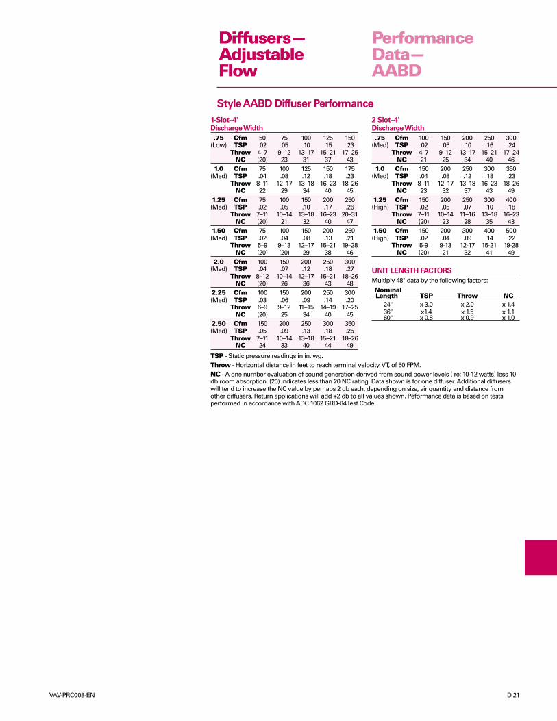
2 Slot–4'Discharge Width
.75 Cfm 100 150 200 250 300(Med) TSP .02 .05 .10 .16 .24
Throw 4–7 9–12 13–17 15–21 17–24NC 21 25 34 40 46
1.0 Cfm 150 200 250 300 350(Med) TSP .04 .08 .12 .18 .23
Throw 8–11 12–17 13–18 16–23 18–26NC 23 32 37 43 49
1.25 Cfm 150 200 250 300 400(High) TSP .02 .05 .07 .10 .18
Throw 7–11 10–14 11–16 13–18 16–23NC (20) 23 28 35 43
1.50 Cfm 150 200 300 400 500(High) TSP .02 .04 .09 .14 .22
Throw 5-9 9-13 12-17 15-21 19-28NC (20) 21 32 41 49
UNIT LENGTH FACTORS
Multiply 48" data by the following factors:Nominal
Length TSP Throw NC24" x 3.0 x 2.0 x 1.436" x1.4 x 1.5 x 1.160" x 0.8 x 0.9 x 1.0
1-Slot–4'Discharge Width
.75 Cfm 50 75 100 125 150(Low) TSP .02 .05 .10 .15 .23
Throw 4–7 9–12 13–17 15–21 17–25NC (20) 23 31 37 43
1.0 Cfm 75 100 125 150 175(Med) TSP .04 .08 .12 .18 .23
Throw 8–11 12–17 13–18 16–23 18–26NC 22 29 34 40 45
1.25 Cfm 75 100 150 200 250(Med) TSP .02 .05 .10 .17 .26
Throw 7–11 10–14 13–18 16–23 20–31NC (20) 21 32 40 47
1.50 Cfm 75 100 150 200 250(Med) TSP .02 .04 .08 .13 .21
Throw 5–9 9–13 12–17 15–21 19–28NC (20) (20) 29 38 46
2.0 Cfm 100 150 200 250 300(Med) TSP .04 .07 .12 .18 .27
Throw 8–12 10–14 12–17 15–21 18–26NC (20) 26 36 43 48
2.25 Cfm 100 150 200 250 300(Med) TSP .03 .06 .09 .14 .20
Throw 6–9 9–12 11–15 14–19 17–25NC (20) 25 34 40 45
2.50 Cfm 150 200 250 300 350(Med) TSP .05 .09 .13 .18 .25
Throw 7–11 10–14 13–18 15–21 18–26NC 24 33 40 44 49
Style AABD Diffuser Performance
D 22 VAV-PRC008-EN
ModelNumberDescription
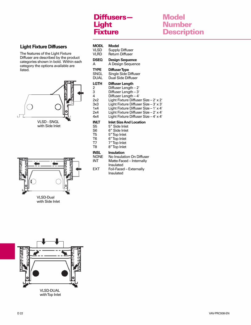
The features of the Light FixtureDiffuser are described by the productcategories shown in bold. Within eachcategory the options available arelisted.
VLSD - SNGLwith Side Inlet
VLSD-Dualwith Side Inlet
VLSD-DUALwith Top Inlet
Light Fixture Diffusers MODL ModelVLSD Supply DiffuserVLRD Return Diffuser
DSEQ Design SequenceA A Design Sequence
TYPE Diffuser TypeSNGL Single Side DiffuserDUAL Dual Side Diffuser
LGTH Diffuser Length2 Diffuser Length – 2'3 Diffuser Length – 3'4 Diffuser Length – 4'2x2 Light Fixture Diffuser Size – 2' x 2'3x3 Light Fixture Diffuser Size – 3' x 3'1x4 Light Fixture Diffuser Size – 1' x 4'2x4 Light Fixture Diffuser Size – 2' x 4'4x4 Light Fixture Diffuser Size – 4' x 4'
INLT Inlet Size And LocationS5 5” Side InletS6 6” Side InletT5 5” Top InletT6 6” Top InletT7 7” Top InletT8 8” Top Inlet
INSL InsulationNONE No Insulation On DiffuserINT Matte-Faced – Internally
InsulatedEXT Foil-Faced – Externally
Insulated
Diffusers—LightFixture
VAV-PRC008-EN D 23
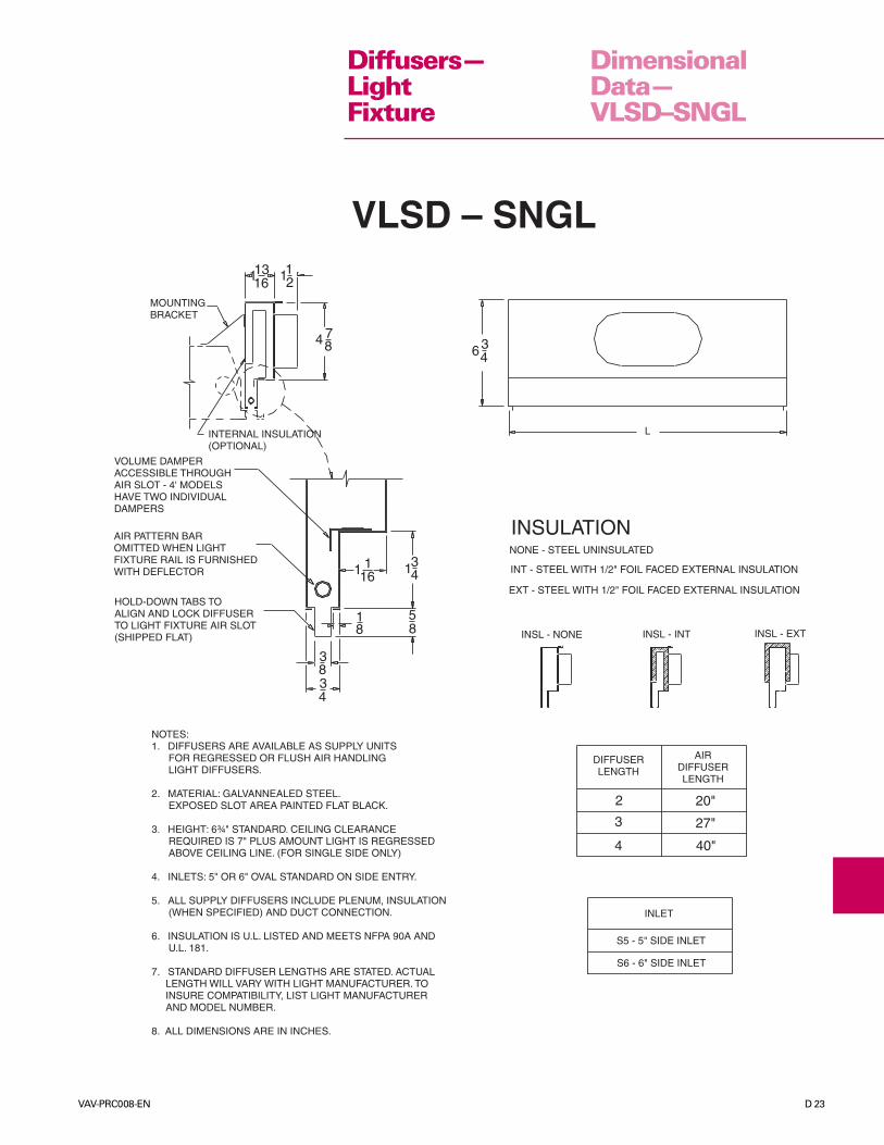
DimensionalData—VLSD–SNGL
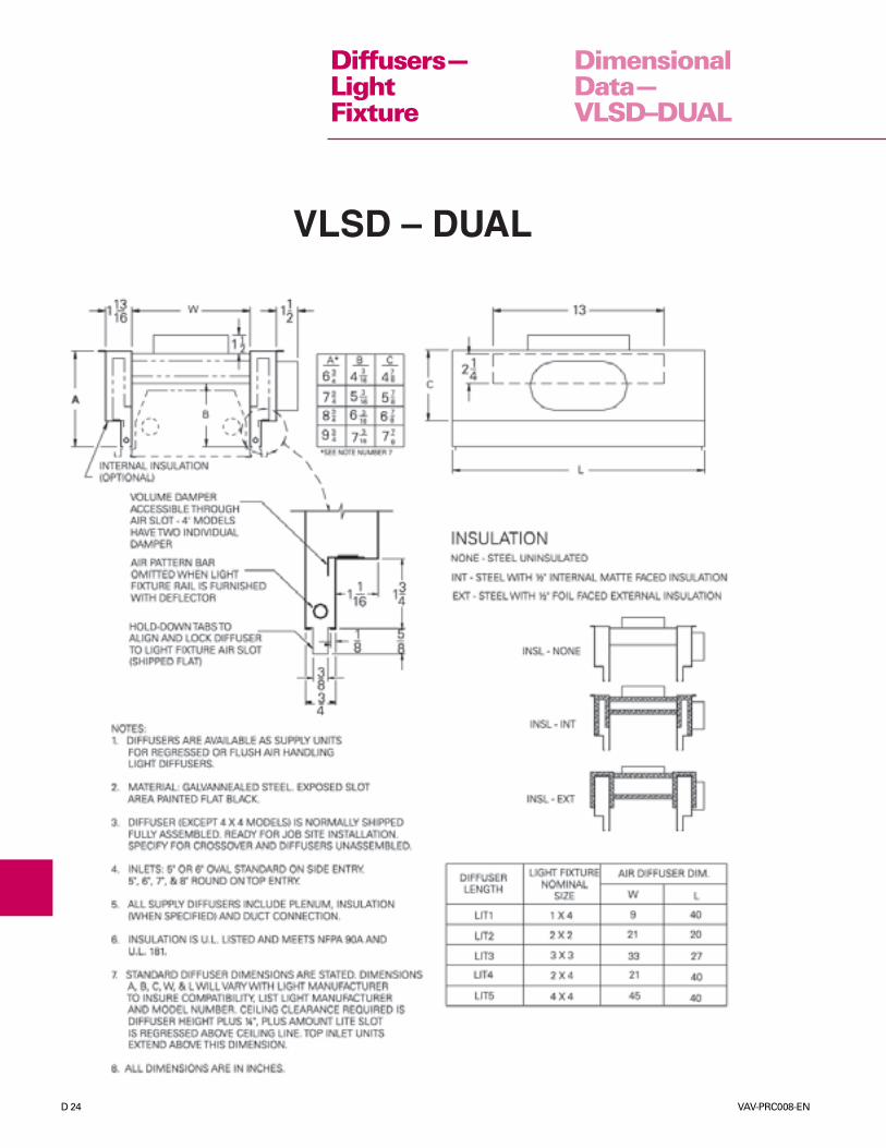
VLSD – SNGL
634
LINTERNAL INSULATION(OPTIONAL)
VOLUME DAMPERACCESSIBLE THROUGHAIR SLOT - 4' MODELSHAVE TWO INDIVIDUALDAMPERS
AIR PATTERN BAROMITTED WHEN LIGHTFIXTURE RAIL IS FURNISHEDWITH DEFLECTOR
HOLD-DOWN TABS TOALIGN AND LOCK DIFFUSERTO LIGHT FIXTURE AIR SLOT(SHIPPED FLAT)
3
1316 112
MOUNTINGBRACKET
INSULATIONNONE - STEEL UNINSULATED
INT - STEEL WITH 1/2" FOIL FACED EXTERNAL INSULATION
EXT - STEEL WITH 1/2" FOIL FACED EXTERNAL INSULATION
INSL - NONE INSL - INT INSL - EXT
1 116
134
58
18
834
DIFFUSERLENGTH
AIRDIFFUSERLENGTH
2
3
4
20"
27"
40"
INLET
S5 - 5" SIDE INLET
S6 - 6" SIDE INLET
NOTES:1. DIFFUSERS ARE AVAILABLE AS SUPPLY UNITS FOR REGRESSED OR FLUSH AIR HANDLING LIGHT DIFFUSERS.
2. MATERIAL: GALVANNEALED STEEL. EXPOSED SLOT AREA PAINTED FLAT BLACK.
3. HEIGHT: 6¾" STANDARD. CEILING CLEARANCE REQUIRED IS 7" PLUS AMOUNT LIGHT IS REGRESSED ABOVE CEILING LINE. (FOR SINGLE SIDE ONLY)
4. INLETS: 5" OR 6" OVAL STANDARD ON SIDE ENTRY.
5. ALL SUPPLY DIFFUSERS INCLUDE PLENUM, INSULATION (WHEN SPECIFIED) AND DUCT CONNECTION.
6. INSULATION IS U.L. LISTED AND MEETS NFPA 90A AND U.L. 181.
7. STANDARD DIFFUSER LENGTHS ARE STATED. ACTUAL LENGTH WILL VARY WITH LIGHT MANUFACTURER. TO INSURE COMPATIBILITY, LIST LIGHT MANUFACTURER AND MODEL NUMBER.
8. ALL DIMENSIONS ARE IN INCHES.
4 78
1
Diffusers—LightFixture
D 24 VAV-PRC008-EN
DimensionalData—VLSD–DUAL
Diffusers—LightFixture
VLSD – DUAL
VAV-PRC008-EN D 25
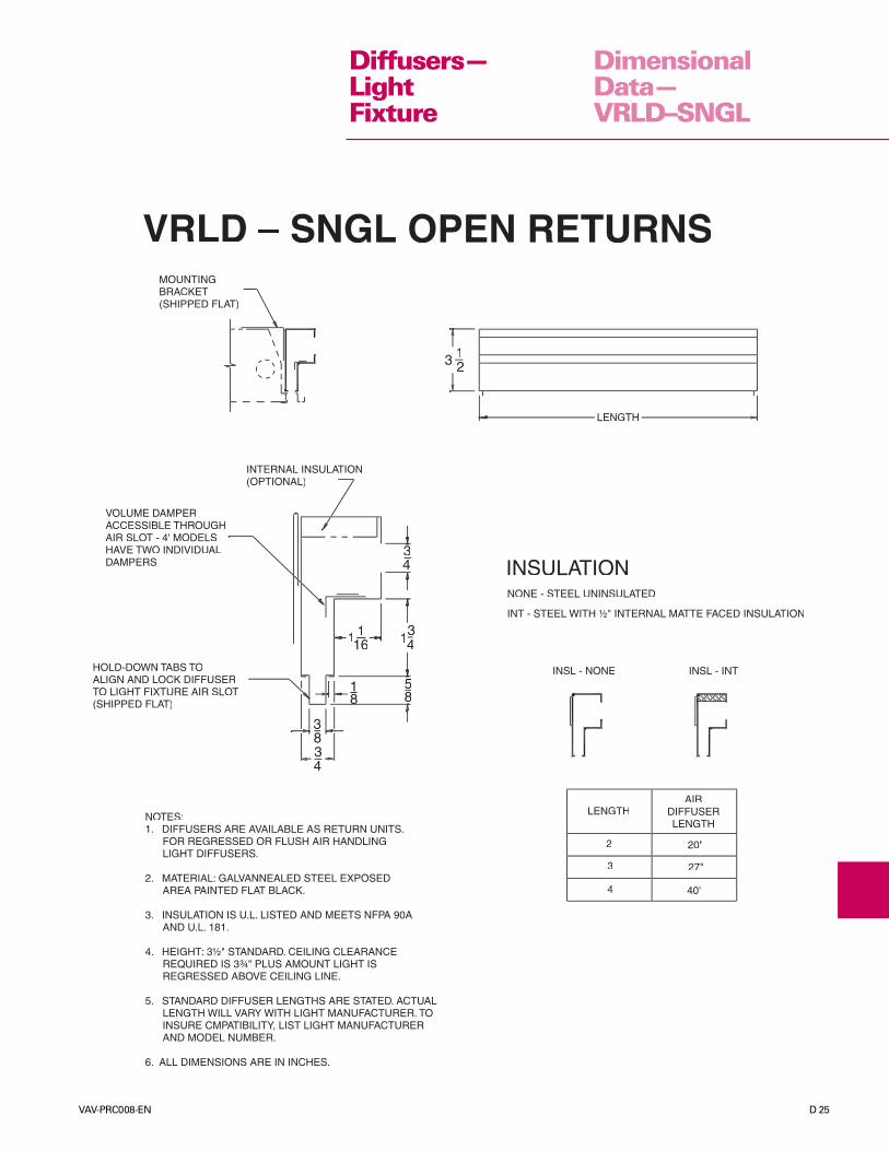
DimensionalData—VRLD–SNGL
VRLD – SNGL OPEN RETURNSMOUNTINGBRACKET(SHIPPED FLAT)
3 12
LENGTH
INSULATIONNONE - STEEL UNINSULATED
INT - STEEL WITH ½" INTERNAL MATTE FACED INSULATION
INSL - NONE
INTERNAL INSULATION(OPTIONAL)
VOLUME DAMPERACCESSIBLE THROUGHAIR SLOT - 4' MODELSHAVE TWO INDIVIDUALDAMPERS
34
1116 13
4
85
2
3
4
20"
27"
40"
LENGTHAIR
DIFFUSERLENGTH
HOLD-DOWN TABS TOALIGN AND LOCK DIFFUSERTO LIGHT FIXTURE AIR SLOT(SHIPPED FLAT)
NOTES:1. DIFFUSERS ARE AVAILABLE AS RETURN UNITS. FOR REGRESSED OR FLUSH AIR HANDLING LIGHT DIFFUSERS.
2. MATERIAL: GALVANNEALED STEEL EXPOSED AREA PAINTED FLAT BLACK.
3. INSULATION IS U.L. LISTED AND MEETS NFPA 90A AND U.L. 181.
4. HEIGHT: 3½" STANDARD. CEILING CLEARANCE REQUIRED IS 3¾" PLUS AMOUNT LIGHT IS REGRESSED ABOVE CEILING LINE.
5. STANDARD DIFFUSER LENGTHS ARE STATED. ACTUAL LENGTH WILL VARY WITH LIGHT MANUFACTURER. TO INSURE CMPATIBILITY, LIST LIGHT MANUFACTURER AND MODEL NUMBER.
6. ALL DIMENSIONS ARE IN INCHES.
Diffusers—LightFixture

D 26 VAV-PRC008-EN
Diffusers—LightFixture
PerformanceData—VLSD
Projection - V and H are vertical and horizontal distance in feet to reach terminal velocities of 100 FPM and 50 FPM respectively.TSP - Static pressure drop in in. wg across the diffuser with dampers full open and horizontal air projection.NC - A one number evaluation of sound generation derived from sound power levels ( re: 10-12 watts) less 8 db room absorption. (20) indicates less than 20 NC rating.Data shown is for one diffuser. Additional diffusers will tend to increase the NC value by perhaps 2 db each, depending on size, air quantity and distance from otherdiffusers. Return applications will add +2 db to all values shown. Performance data is based on tests performed in accordance with ADC 1062 GRD-84 Test Code.
VLSD-DUALTop inlet–2’
CFM 50 60 70 80 90 100 110 120Throw-V 3–5 4–6 5–7 5–8 6–8 6–9 7–9 7–10Throw-H 2–4 4–8 6–10 7–10 7–11 8–11 8–12 9–13TSP-5" .05 .07 .09 .12 .15 .18 .22 .26TSP-6" .04 .06 .08 .10 .13 .16 .19 .23
NC (20) (20) (20) 22 26 31 33 36
VLSD-DUALTop inlet–3’
CFM 90 100 110 120 130 140 150 160Throw-V 3–5 3–6 4–6 4–6 5–7 6–7 6–8 6–9Throw-H 4–6 5–7 6–8 6–9 7–9 7–10 8–11 8–12TSP-5" .08 .10 .12 .15 .18 .20 .23 .28TSP-6" .08 .09 .11 .13 .16 .18 .20 .23
NC 20 23 26 28 32 33 34 37
VLSD-DUALTop inlet–4’
CFM 60 80 100 120 140 160 180 200Throw-V 1–2 1–3 2–3 2–4 3–5 4–6 5–7 6–8Throw-H 2–3 2–4 3–5 4–6 4–7 5–8 6–9 7–10TSP-5" .03 .06 .09 .13 .17 .22 .28 .35TSP-6" .03 .05 .08 .10 .14 .18 .23 .29
NC (20) (20) 21 24 31 33 37 41
Style LITE Diffuser Performance
VLSD-SNGLSide inlet–2'
Cfm 30 40 50 60 70 80 90 100Throw-V 3–4 4–6 5–7 6–8 7–9 8–10 9–10 9–11Throw-H 6–8 7–10 8–12 9–13 10–14 11–15 12–16 13–17TSP-5" .04 .08 .13 .19 .25 .32 .41 50TSP-6" .04 .08 .12 .18 .24 .31 .39 .48
NC (20) (20) 22 29 33 36 41 44
VLSD-SNGLSide inlet–3'
Cfm 40 50 60 70 80 90 100 110Throw-V 3–5 4–6 5–7 6–8 6–9 7–9 7–10 8–10Throw-H 4–6 5–8 6–10 8–11 9–13 10–14 11–15 12–16TSP-5" .04 .06 .09 .12 .17 .21 .27 .32TSP-6" .04 .06 .08 .11 .15 .19 .24 .29
NC (20) (20) (20) 23 27 32 35 39
VLSD-SNGLSide inlet–4'
Cfm 50 60 70 80 90 100 110 120Throw-V 3–4 4–5 5–6 5–7 6–8 6–8 6–9 7–9Throw-H 4–6 5–7 5–8 6–9 7–10 7–11 8–12 9–13TSP-5" .04 .06 .08 .11 .15 .17 .21 .25TSP-6" .04 .06 .08 .11 .14 .16 .20 .23
NC (20) (20) (20) 23 27 30 34 37
VLSD-DUALSide Inlet–2'
Cfm 50 60 70 80 90 100 110 120Throw-V 3–5 4–6 5–7 5–8 6–8 6–9 7–9 7–10Throw-H 2–4 4–8 6–10 7–10 7–11 8–11 8–12 9–13TSP-5" .05 .06 .08 .10 .13 .16 .19 .23TSP-6" .04 .06 .08 .10 .12 .15 .18 .21
NC (20) (20) (20) 21 25 29 32 36
VLSD-DUALSide Inlet–3'
Cfm 90 100 110 120 130 140 150 160Throw-V 3–5 3–6 4–6 4–6 5–7 6–7 6–8 6–9Throw-H 4–6 5–7 6–8 6–9 7–9 7–10 8–11 8–12TSP-5" .07 .08 .10 .12 .14 .17 .19 .22TSP-6" .06 .07 .09 .11 .13 .15 .17 .19
NC (20) 20 23 25 29 30 33 34
VLSD-DUALSide Inlet–4'
Cfm 60 80 100 120 140 160 180 200Throw-V 1–2 1–3 2–3 2–4 3–5 4–6 5–7 6–8Throw-H 2–3 2–4 3–5 4–6 4–7 5–8 6–9 7–10TSP-5" .02 .04 .07 .10 .13 .16 .21 .26TSP-6" .02 .04 .06 .08 .11 .15 .19 .23
NC (20) (20) (20) 21 26 30 33 37
VAV-PRC008-EN D 27
ModelNumberDescription
Diffusers—Induction
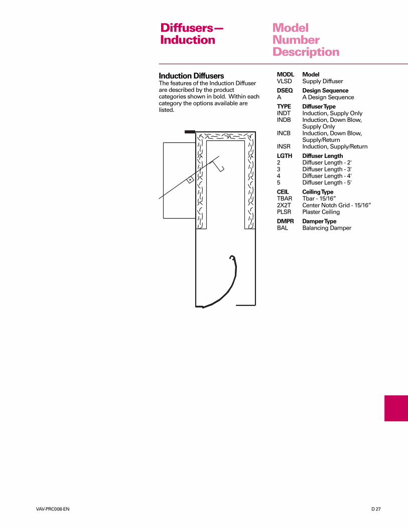
Induction DiffusersThe features of the Induction Diffuserare described by the productcategories shown in bold. Within eachcategory the options available arelisted.
MODL ModelVLSD Supply Diffuser
DSEQ Design SequenceA A Design Sequence
TYPE Diffuser TypeINDT Induction, Supply OnlyINDB Induction, Down Blow,
Supply OnlyINCB Induction, Down Blow,
Supply/ReturnINSR Induction, Supply/Return
LGTH Diffuser Length2 Diffuser Length - 2'3 Diffuser Length - 3'4 Diffuser Length - 4'5 Diffuser Length - 5'
CEIL Ceiling TypeTBAR Tbar - 15/16”2X2T Center Notch Grid - 15/16”PLSR Plaster Ceiling
DMPR Damper TypeBAL Balancing Damper
D 28 VAV-PRC008-EN
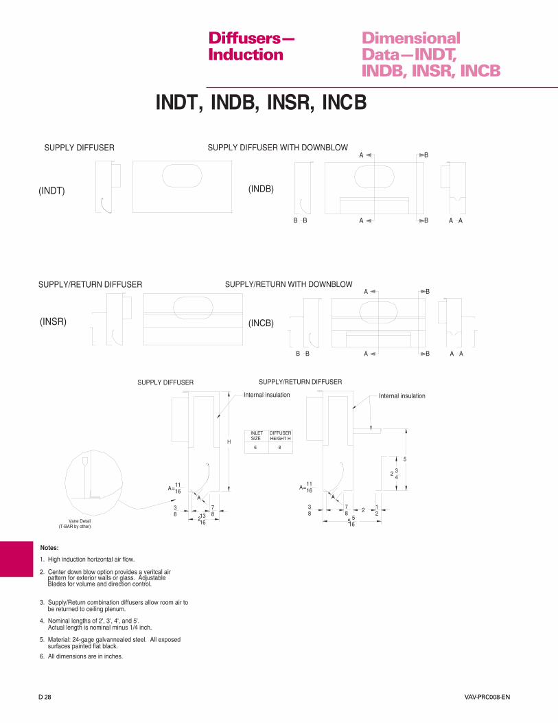
Diffusers—Induction
DimensionalData—INDT,INDB, INSR, INCB
SUPPLY/RETURN DIFFUSER
Internal insulation Internal insulation
(INCB)
BB A A AB
1611
=A
38
221
55
78
16
INDT, INDB, INSR, INCB
SUPPLY DIFFUSER WITH DOWNBLOW
SUPPLY/RETURN WITH DOWNBLOWSUPPLY/RETURN DIFFUSER
B
(INSR)
B
A
A
ASUPPLY DIFFUSER
(INDT)
(T-BAR by other)
B
Vane Detail
A AB
B
A=
83
1611
16132
87
SUPPLY DIFFUSER
324
5
8
HEIGHT HDIFFUSER
6
SIZEINLET
4. Nominal lengths of 2', 3', 4', and 5'.Actual length is nominal minus 1/4 inch.
be returned to ceiling plenum.
pattern for exterior walls or glass. Adjustable
1. High induction horizontal air flow.
2. Center down blow option provides a veritcal air
3. Supply/Return combination diffusers allow room air to
Notes:
surfaces painted flat black.5. Material: 24-gage galvannealed steel. All exposed
Blades for volume and direction control.
(INDB)
6. All dimensions are in inches.
VAV-PRC008-EN D 29
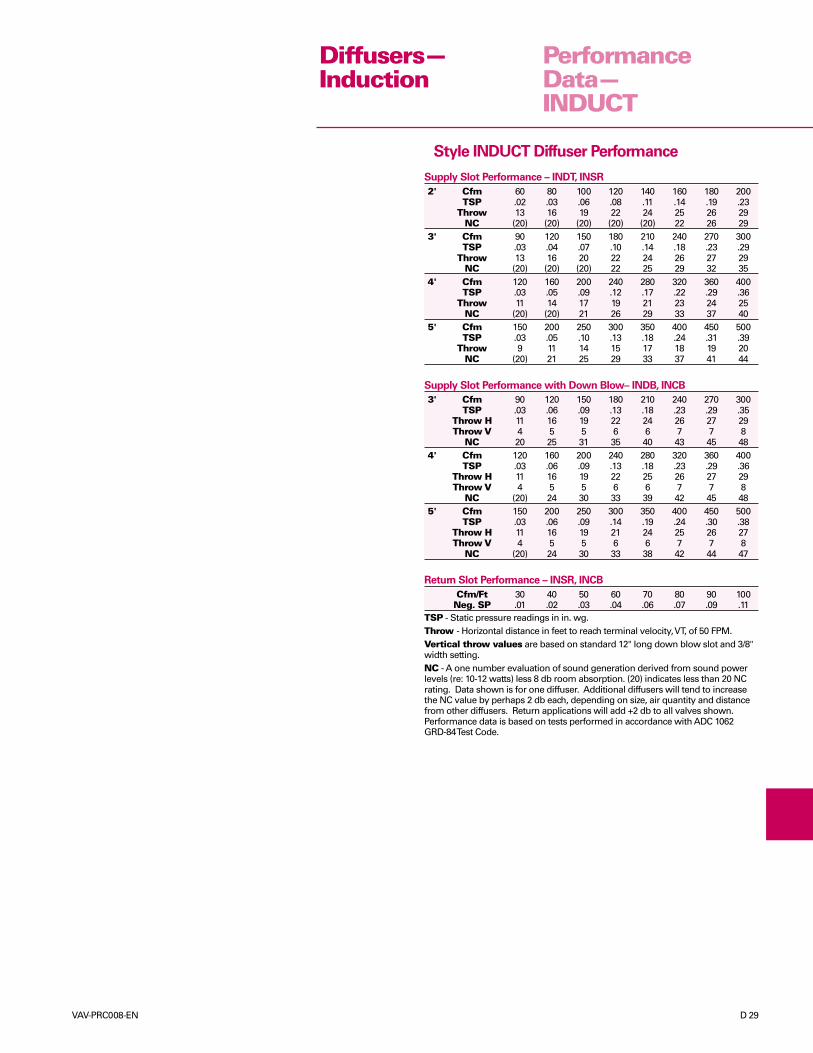
TSP - Static pressure readings in in. wg.Throw - Horizontal distance in feet to reach terminal velocity, VT, of 50 FPM.Vertical throw values are based on standard 12" long down blow slot and 3/8"width setting.NC - A one number evaluation of sound generation derived from sound powerlevels (re: 10-12 watts) less 8 db room absorption. (20) indicates less than 20 NCrating. Data shown is for one diffuser. Additional diffusers will tend to increasethe NC value by perhaps 2 db each, depending on size, air quantity and distancefrom other diffusers. Return applications will add +2 db to all valves shown.Performance data is based on tests performed in accordance with ADC 1062GRD-84 Test Code.
PerformanceData—INDUCT
Diffusers—Induction
Style INDUCT Diffuser Performance
Supply Slot Performance – INDT, INSR
2' Cfm 60 80 100 120 140 160 180 200TSP .02 .03 .06 .08 .11 .14 .19 .23
Throw 13 16 19 22 24 25 26 29NC (20) (20) (20) (20) (20) 22 26 29
3' Cfm 90 120 150 180 210 240 270 300TSP .03 .04 .07 .10 .14 .18 .23 .29
Throw 13 16 20 22 24 26 27 29NC (20) (20) (20) 22 25 29 32 35
4' Cfm 120 160 200 240 280 320 360 400TSP .03 .05 .09 .12 .17 .22 .29 .36
Throw 11 14 17 19 21 23 24 25NC (20) (20) 21 26 29 33 37 40
5' Cfm 150 200 250 300 350 400 450 500TSP .03 .05 .10 .13 .18 .24 .31 .39
Throw 9 11 14 15 17 18 19 20NC (20) 21 25 29 33 37 41 44
Supply Slot Performance with Down Blow– INDB, INCB
3' Cfm 90 120 150 180 210 240 270 300TSP .03 .06 .09 .13 .18 .23 .29 .35
Throw H 11 16 19 22 24 26 27 29Throw V 4 5 5 6 6 7 7 8
NC 20 25 31 35 40 43 45 484' Cfm 120 160 200 240 280 320 360 400
TSP .03 .06 .09 .13 .18 .23 .29 .36Throw H 11 16 19 22 25 26 27 29Throw V 4 5 5 6 6 7 7 8
NC (20) 24 30 33 39 42 45 485' Cfm 150 200 250 300 350 400 450 500
TSP .03 .06 .09 .14 .19 .24 .30 .38Throw H 11 16 19 21 24 25 26 27Throw V 4 5 5 6 6 7 7 8
NC (20) 24 30 33 38 42 44 47
Return Slot Performance – INSR, INCB
Cfm/Ft 30 40 50 60 70 80 90 100Neg. SP .01 .02 .03 .04 .06 .07 .09 .11
D 30 VAV-PRC008-EN
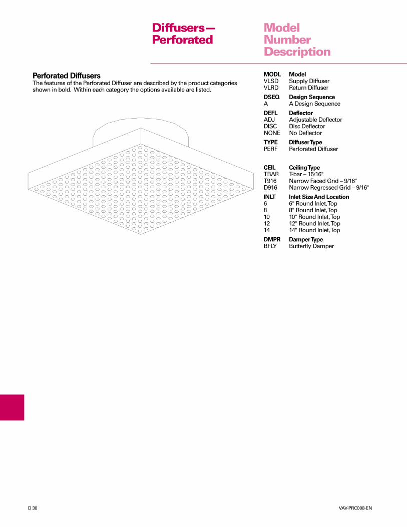
Diffusers—Perforated
ModelNumberDescription
Perforated DiffusersThe features of the Perforated Diffuser are described by the product categoriesshown in bold. Within each category the options available are listed.
MODL ModelVLSD Supply DiffuserVLRD Return Diffuser
DSEQ Design SequenceA A Design Sequence
DEFL DeflectorADJ Adjustable DeflectorDISC Disc DeflectorNONE No Deflector
TYPE Diffuser TypePERF Perforated Diffuser
CEIL Ceiling TypeTBAR T-bar – 15/16"T916 Narrow Faced Grid – 9/16"D916 Narrow Regressed Grid – 9/16"
INLT Inlet Size And Location6 6" Round Inlet, Top8 8" Round Inlet, Top10 10" Round Inlet, Top12 12" Round Inlet, Top14 14" Round Inlet, Top
DMPR Damper TypeBFLY Butterfly Damper

VAV-PRC008-EN D 31
DimensionalData—PERF
Diffusers—Perforated
PERFBUTTERFLY DAMPERR(OPTIONAL FOR VLSD ONLY)
1½
DISC OR ADJUSTABLE DEFLECTOR(FOR VLSD ONLY)
24" CENTERS
16 T-BARS
DEFL
ADJDISC DEFLECTOR (VLSD ONLY)( )ADJUSTABLE DEFLECTOR (VLSD ONLY)NO DEFLECTOR (VLRD ONLY)
INLT
68
1214
6" TOP INLET8" TOP INLET
12" TOP INLET14" TOP INLET
NOTES:1. COMPLETELY ASSEMBLED FOR EASY LAY-IN INSTALLATION.
2. 22-GAGE PERFORATED STEEL FACE WITH WHITE FINISH AND 51% OPEN AREA.
3. 24-GAGE STEEL PLENUM WITH BLACK INTERIOR. THE FACE FOR LEFT, RIGHT, OR VERTICAL THROW.
4. ROUND INLET SIZES 6" THROUGH 14".
5. AVAILABLE WITH DISC OR ADJUSTABLE DEFLECTOR.
6. ALL DIMENSIONS ARE IN INCHES.

D 32 VAV-PRC008-EN
Diffusers—Perforated
PerformanceData—PERF
TSP - Total pressure readings in in. wg across diffuser.Throw - Horizontal distances in feet to reach terminal velocity, VT, of 50 FPM.NC - A one number evaluation of sound generation derived from sound power levels (re:10-12 watts) less 10 db room absorption. (20) indicates less than 20 NC rating. Data shownis for one diffuser. Additional diffusers will tend to increase the NC value by perhaps 2 dbeach, depending on size, air quantity and distance from other diffusers. Return applicationswill add +2 db to all valves shown. Performance data is based on tests performed at DoncoAir Products and ETL Laboratories in accordance with ADC 1062 GRD-84 Test Code.
Table 1 - Style PERF Diffuser Performance
24 x 24 Nominal sizeInlet Size
6 Cfm 60 80 100 120 135 158 176 195 234TSP .01 .01 .02 .03 .04 .05 .06 .08 .12
Throw 1 2 3 3 4 4 5 5 6NC — — — 20 21 23 27 30 35
8 Cfm 104 139 175 210 245 280 315 350 420TSP .01 .02 .03 .04 .05 .06 .08 .10 .14
Throw 2 3 4 4 5 6 7 7 8NC — — — 20 26 29 33 35 40
10 Cfm 165 220 275 325 380 435 490 545 650TSP .01 .02 .03 .04 .06 .08 .10 .12 .18
Throw 2 4 5 5 6 7 8 8 9NC — — 20 24 29 33 36 39 44
12 Cfm 240 315 395 475 550 630 710 785 945TSP .01 .02 .04 .05 .07 .09 .12 .14 .20
Throw 3 4 5 6 7 9 9 10 11NC — — 22 28 32 36 39 42 49
14 Cfm 320 430 536 640 747 856 960 1070 1281TSP .01 .02 .04 .06 .08 .10 .13 .16 .23
Throw 3 5 6 7 8 10 10 11 12NC — 20 25 30 36 39 42 45 50
VAV-PRC008-EN D 33
MODEL VLSD and VLRDSupply and Return Diffusers.
LINR1. General Casing—This diffuser is
constructed of 24-gagegalvannealed steel. Hanger holeson each end of the diffuser forinstallation are optional. Slot edgesformed over; provide doublethickness tile support as an integralpart of the diffuser housing. Allexposed surfaces are finished withwhite enamel.
2. Insulation—The interior surface ofthe diffuser casing is acoustically-and thermally-lined with ½-inch(13 mm) 1.9 lb cu ft (30.4 kgs/cu m),R-Value of 2.1 density glass fiberwith high-density facing. Theinsulation is UL listed and meetsNFPA-90A and UL 181 standards.
3. T-Bar Ceiling—This diffuser isdesigned to install over the “T” ofmost standard exposed suspendedceilings. The end angle is providedto allow the slot to fit flush with thebottom of the “T” and ceiling tile.
4. 2x2 T-Bar Ceiling—This diffuser isdesigned to install over the “T” ofmost standard exposed suspendedceilings. The notch is provided inthe middle of the unit to allow thediffuser to set over the “T” locatedat the middle point.
5. Concealed Spline Ceiling—Thediffuser is designed to sit in thecenter of the module, parallel to themain ceiling support member. Theceiling tile rests on the edge of thedischarge slot and the flange. At-bar insert is provided in the centerof a two-way throw diffuser, whenapplicable.
6. Plaster Ceiling—The diffuser isdesigned to sit into the opening inthe plaster. The diffuser must beused in conjunction with a trimframe for a finished appearance.
7. Trim Frame—The trim frame isextruded aluminum and designedto attach to the diffuser slot(s) withclips. The trim frame is finished withwhite enamel and is designed toset into the opening of a plasterceiling for a finished appearance.
8. Fire Damper—An integral fusiblelink, 22-gage factory installed firedamper. The fusible link has amelting point of 158°F (70°C).
9. Inlet Balancing Damper—Afactory-provided and -installedsingle-blade damper, with a
position-locating handle forbalancing air.
10. Inlet—The inlet connection is sizedto fit standard, round, flexibleductwork.
11. Agency Listing—UL listed asenvironmental air terminal unit.Control #419X (1- and 2-slot only).
FAPF, VAPF, VAPS, AABD1. General Casing—This diffuser is
constructed of 24-gagegalvannealed steel. All exposedsurfaces of the diffuser are finishedwith flat black enamel. Factory-installed t-bars are finished withwhite enamel.
2. Insulation—The interior surface ofthe supply diffuser casing isacoustically- and thermally-linedwith ½-inch (13 mm) 1.9 lb/cu ft(30.4 kg/cu m), R-Value of2.1 density glass fiber with high-density facing. The insulation is ULlisted and meets NFPA-90A andUL 181 standards.
3. T-Bar Ceiling—This diffuser isdesigned to install over the “T” ofmost standard exposed suspendedceilings. The end angle is providedto allow the slot to fit flush with thebottom of the “T” and ceiling tile.
4. 2x2 T-Bar Ceiling—This diffuser isdesigned to install over the “T” ofmost standard exposed suspendedceilings. The notch is provided inthe middle of the unit to allow thediffuser to set over the “T” locatedat the middle point.
5. Plaster Ceiling—The diffuser isdesigned to set into the opening inthe plaster. The diffuser must beused in conjunction with a trimframe for a finished appearance.The trim frame is extrudedaluminum with white finish.
6. Inlet Balancing Damper—Afactory-provided and -installedsingle-blade damper, with aposition-locating handle forbalancing air.
7. Inlet – The inlet connection is sizedto fit standard, round, flexibleductwork.
INDT1. General Casing – This diffuser
is constructed of 24-gagegalvannealed steel. Exposedsurfaces are finished with flatblack enamel.
2. Insulation – The interior surface ofthe diffuser casing is acoustically-and thermally-lined with ½-inch
(13 mm) 1.9 lb cu ft (30.4 kgs/cu m),R-Value of 2.1 density glass fiberwith high-density facing. Theinsulation is UL listed and meetsNFPA-90A and UL 181 standards.
3. T-Bar Ceiling—This diffuser isdesigned to install over the “T”of most standard exposedsuspended ceilings.
4. 2x2 T-Bar Ceiling—This diffuser isdesigned to install over the “T” ofmost standard exposed suspendedceilings. The notch is provided inthe middle of the unit to allow thediffuser to set over the “T” locatedat the middle point.
5. Plaster Ceiling—The diffuser isdesigned to set into the opening inthe plaster. The diffuser must beused in conjunction with a trimframe, for a finished appearance.The trim frame is extrudedaluminum and designed to attachto the diffuser slot with clips. Thetrim frame is finished with whiteenamel.
6. Inlet Balancing Damper—Afactory-provided and -installedsingle-blade damper, with aposition-locating handle forbalancing air.
7. Inlet—The inlet connection is sizedto fit standard, round, flexibleductwork.
LITE1. General Casing—This diffuser is
constructed of 24-gagegalvannealed steel. Hold-down tabson the diffuser ends are provided toalign and lock the diffuser to thelight air slot. Exposed slot area ispainted flat black.
2. Insulation—Optional. If used, theinterior surface of the diffusercasing is acoustically and thermallylined with ½ inch (13 mm) 1.9 lb cuft (30.4 kgs/cu m), R-Value of 2.1density glass fiber with high-density facing. The insulation is ULlisted and meets NFPA-90A andUL 181 standards. The externalinsulation is foil-faced.
3. Dual Side Diffuser—This diffuseris designed for dual-sideinstallation on the light fixture.
4. Single Side Diffuser—Thisdiffuser is designed for single-sideinstallation on the light fixture. Aside bracket is provided for extrasupport.
5. Inlet—The inlet connection is sizedto fit standard, round, flexibleductwork.
MechanicalSpecifications
Diffusers
D 34 VAV-PRC008-EN
PERF1. General Casing—This diffuser
plenum is constructed of 24-gagegalvannealed steel with blackinterior. The diffuser face is 22-gageperforated steel with a white finishand 51% open area.
2. Adjustable Deflector—A set offour square louver-type deflectorsattached to the backside of theperforated panel, directly below theinlet collar. Each deflector pivots toallow for one-, two-, three-, andfour-way horizontal air patterns.Factory-set at a four-way air pattern.
Diffusers—Perforated
MechanicalSpecifications
3. Disc Deflector—A round discattached to the backside of theperforated panel, directly below theinlet collar to deflect the air in a360° horizontal air pattern.
4. T-Bar Ceiling—This diffuser isdesigned for easy lay-in installationin the suspended T-bar ceiling grid.
5. Butterfly Damper—A two-bladedvolume damper located in the inletcollar. Adjustments are madethrough the perforated metal with a screwdriver.
6. Inlet – The inlet connection is sizedto fit standard, round, flexibleductwork.