trane variable frequency drives troubleshooting -...
TRANSCRIPT

Trane Variable Frequency Drives Troubleshooting

Trane ComfortSite is a user-friendly Internet site designed to
save you time and it’s FREE for Trane Customers.
· Order Equipment, Parts, Literature and track Order Status
· Register for Training Programs
· Complete Warranty requirements online
· Search for specific Product Information
· Use interactive Product Support functions
· View account history and print invoices through Account Track Online
· And More!
Make every business day more productive by using Trane ComfortSite.
ComfortSite website: https://www.comfortsite.com/ebiz/
Not a registered user and want to learn more?
Contact your local Trane Parts Distributor at (800) 585-2591.
Need help locating your distributor?
E-mail us at: [email protected]


Touching the electrical parts may be fatal —
even after the equipment has been
disconnected from the AC line. To be sure
that the capacitors have fully discharged,
wait 14 minutes after power has been
removed before touching any internal
component!
DANGER!


BASIC INFORMATION AND REQUIRED EQUIPMENT
• REQUIRED REFERENCE MATERIAL
• REQUIRED TOOLS
• POSSIBLE USEFUL EQUIPMENT
• WHAT IS TROUBLESHOOTING
• DIVIDE AND CONQUER
• PHYSICAL INSPECTION

Required Reference Material YOU MUST HAVE THIS!
• INSTALLATION, OPERATION AND
MAINTENANCE MANUAL (GENERAL
INFORMATION)
• CUSTOMER CONNECTION DIAGRAM
(SPECIFIC FOR THE ORDER)
• SCHEMATIC DIAGRAM (SPECIFIC
FOR THE ORDER)

Hand tools Tool’s required
Screwdrivers, Standard & Phillips
Torx drivers T10-T50
Metric socket set, 7-17 mm
Lon extension (20”)
Torque wrench, 4-170 in./lb
Magnet
Nut starter

Meters
• PWM compatible voltmeter
• Clamp-on ammeter

Additional tools
• 1000 v Insulation tester
• Laptop with system software
• Cell phone
• Oscilloscope (with Isolated case)

First thing
• Do not apply power until you
complete the static tests

The Troubleshooting approach
• Take the logical approach
– Take it all in
Use all you senses
Perform physical inspection
Do a process of elimination
Make alignment with sequence of operation
Align with what is to what should be
– What does the display tell you
– check the programing
– How does the drive look on the inside

Check it out
• Installation
• Connection
• Environment
• Fuses
• Burnt marks or smell

VFD sections
• Regulator—Controls the rectifier and inverter to
produce the desired ac frequency and voltage.
• Rectifier—Converts the fixed 60 Hz ac voltage input
to dc.
• Inverter—Switches the rectified dc voltage to ac,
creating variable ac frequency (and controlling
current flow, if desired).

• VFDs convert AC to DC…then DC to AC
(at varying frequency and voltage)
460 V, 60 Hz 640 V, DC 307 V, 40 Hz
AC DC AC
Rectifier Inverter
VFD Introduction
VFDs allow the motor to operate and consume electricity as if it
were the right sized horsepower for the job.

TROUBLESHOOTING THE DRIVE THAT WORKS IN HAND MODE.
• Before moving on try taking a voltage and current
reading on the input and output of the drive. Both
should be balanced. The output voltage must be
balanced within a volt phase to phase with the motor
connected.

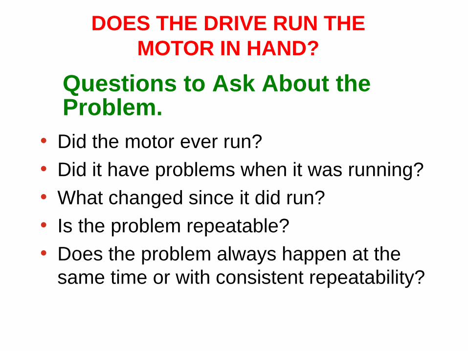
Questions to Ask About the Problem.
• Did the motor ever run?
• Did it have problems when it was running?
• What changed since it did run?
• Is the problem repeatable?
• Does the problem always happen at the same time or
with consistent repeatability?
DOES THE DRIVE RUN THE
MOTOR IN HAND?

DOES THE DRIVE RUN THE MOTOR IN HAND?
• At this point try to run the motor using the hand
start function of the drive.
• Press the hand start key and slowly begin to
increase the speed of the motor by pressing the
plus key.

TROUBLESHOOTING THE DRIVE THAT WORKS IN HAND MODE.
• If the drive works the motor up and down in speed
when in the hand mode, the drive is probably good.
Questions to Ask About the Problem.
• Did the motor ever run?
• Did it have problems when it was running?
• What changed since it did run?
• Is the problem repeatable?
• Does the problem always happen at the
same time or with consistent repeatability?
DOES THE DRIVE RUN THE
MOTOR IN HAND?

The Motor Won’t Run in Bypass Is there power to the bypass?
– Are the main or bypass fuses OK?
– Is the safety interlock closed? (TB1: 1 & 2)
– Is the motor overload tripped?
– Is the motor connected?
– For some drives: Is the building automation
system giving a run command? (TB1: 2 & 3) (Use the customer connection diagram and bypass schematic for the
drive to determine this.)

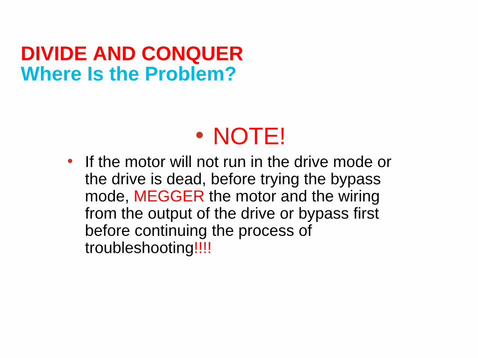
DIVIDE AND CONQUER Where Is the Problem?
NOTE!
• If the motor will not run in the drive mode or
the drive is dead, before trying the bypass
mode, MEGGER the motor and the wiring
from the output of the drive or bypass first
before continuing the process of
troubleshooting!!!!

HOW TO MEGGER A MOTOR

Motor wiring

Know your motor wiring


Position A B C
T0 ++ - -
T1 + + - -
T2 - ++ -
T3 - - + +
T4 - - ++
T5 + - - +
T6 ++ - -


DIVIDE AND CONQUER Where Is the Problem?
• NOTE! • If the motor will not run in the drive mode or
the drive is dead, before trying the bypass mode, MEGGER the motor and the wiring from the output of the drive or bypass first before continuing the process of troubleshooting!!!!

HOW TO MEGGER A MOTOR

TWO MODES OF FAILURE:
WINDING FAILURE
BEARING FAILURE
MOTOR PROBLEMS

MOTOR PROBLEMS
Coil Breakdown at the
point of exit from the
core
COIL FAILURES
Coil Breakdown at the
crown point due to high
voltage spiking.

MOTOR PROBLEMS
Ground Fault failure at the core.

MOTOR PROBLEMS Complete coil failure due
to all or partial loss of
phase.

MOTOR PROBLEMS
BEARING FAILURES
DUE TO POSSIBLE
DRIVE RELATE
PROBLEMS
BEARING FLUTING
CAUSED BY
ELECTROSTATIC
DISCHARGE

42
= 460 VAC
60Hz
Electric Motor Design
Most electric induction motors were designed for operation on 3 phase sign wave power – either 50 or 60 Hz.
The input power was balanced in frequency, phase (120 degrees apart) and in amplitude.
Common mode voltage – the sum of the 3 phases would always equal zero volts.

43
+
Electric Motor Operation by VFD
When operated by VFD, the power to the motor is a series of pulses instead of a smooth sign wave.
The input power is never balanced because the voltage is either 0 volts, positive, or negative with rapid switching between pulses.
The Three phases of voltage pulses ensures that the common mode voltage is never equal to zero and instead is a “square wave” or “6 step” voltage.
=

44
Shaft Voltage Readings

PWM Drives Cause
1. High frequency transients (dv/dt) can break down the insulation between windings and cause corona discharge arcing which can short out the windings.
2. Because of the inherent voltage imbalance and dv/dt, the voltage pulses are capacitively induced on the motor shaft and can overcome the dielectric of the oil film in the motor bearings. Electrical discharges result in pitting and fluting damage in the bearing, breakdown of lubrication, and fluting failure of the bearing.

46
Motor Reliability for Inverter Driven Motors
Motor Winding Problems The motor winding insulation was changed to withstand the transient voltages and to prevent the corona discharges. NEMA MG1 specified motor design to meet what was known as “class F, G or H” insulation, and “corona resistant wire” was developed.
The problem of electrical bearing damage was identified in the NEMA MG1 with for motors above and below NEMA frames
NEMA recommended to use either ceramic bearings or shaft grounding. Shaft grounding also protects attached equipment.

Stator
Rotor
Groun
d
VF
D D
rive
VFD Induced Voltages
VFD induced capacitive voltages from the high switching speed of the pulse
width modulation (PWM) drives discharge through motor bearings and cause
electrical discharge machining (EDM) effect in the bearing race.
Rotor ground currents generated by PWM Drive will partly flow as rotor
ground current through the bearings of the motor. These currents are caused
by the rotor being connected to common ground with a significantly lower
impedance path then the ground of the stator housing.
VFD Induced Shaft Voltages and Bearing
Currents in AC Motors
Shaft
Groun
d
Groun
d

Motors below 500 Frame (NEMA 56 to 449T):
More recently…potentially destructive bearing currents have occasionally occurred in much smaller motors… These drives can be generators of a common mode voltage which…oscillates at high frequency and is capacitively coupled to the rotor. This results in peak pulses as high as 10-40 volts from shaft to ground… Interruption of this current therefore requires insulating both bearings.
Alternately, shaft grounding brushes may be used to divert the current around the bearing.
It should be noted that insulating the motor bearings will not prevent the damage of other shaft connected equipment.
NEMA MG1 section 31.4.4.3

High Frequency Circulating Currents in Large AC, DC Motors & Generators
Stator
Rotor
Groun
d
Shaft Currents
Induced by the magnetic flux imbalance around the motor shaft from the
stator windings, these currents circulate through the motor bearings.
Circulating currents are a problem in large AC and DC motors of over 100 hp.
Because these currents circulate through the motor via the shaft and
bearings, the current flow must be either broken or an alternate path
established to prevent bearing failures.
Shaft
Groun
d
Groun
d
High Frequency Flux encircling the rotor causing shaft bearing
currents

Large Frame Motors (500 frame or larger): …voltages may be
present under sinusoidal operation and are caused by magnetic
dissymmetry's in the construction of these motors…current
path…is from the motor frame through a bearing to the motor
shaft, down the shaft, and through the other bearing back to the
motor frame. This type of current can be interrupted by insulating
one of the bearings.
NEMA MG1 section 31.4.4.3
When VFD is used, the circulating currents described
above increase from 60 Hz to KHz or MHz frequencies
and may effect motors rated at 150 kW (200 HP). This is
referred to as “High Frequency Circulating Current” Reference: A. Muetze, A. Binder, H. Vogel, J. Hering, “What can bearings bear? – How much
current is too much? How much current reduction enough?” IEEE Magazine on
Industry Applications, vol. 12, no. 6, pp. 57-64, November/December 2006.

Bearing Failure
March 2005 Journal of Electrostatics “Statistical model of electrostatic discharge hazard in bearings of induction motor fed by inverter” by Adam Kempski et. al. “Electrical Discharge Machining (EDM) bearing currents have been found as the main cause of premature bearing damages in Pulse Width Modulation (PWM) inverter fed drives.”
February 2007: Pump and Systems Magazine “How to Prevent Electrical Erosion in Bearings” by Daniel R. Snyder, P.E., SKF USA Inc. “An estimated 50 percent of all electric motor failures are attributed to bearings, but the bearings themselves are not usually the root cause. Other forces are at work, such as the increasingly common problem of stray currents.”

52
Motor Bearing Damage from Electrical Currents
Electrical Discharge Machining (EDM)
Bearing Pitting Damage
Bearing Fluting Damage
Electron Microscope
(SEM) Image
EDM Pitting
1000x Magnified
EDM Pit

53
Mitigation Strategies
Ground the shaft with spring loaded
brush
– Copper phosphor or bronze metal
brush
– Carbon block brush
Isolate the shaft from the frame of the
motor
- Use insulated sleeve on the
bearing journal
- Replace steel bearings with
ceramic bearings

54
New Conductive Microfiber Shaft GroundingTechnology
Uses several methods to transfer
electrical currents*
*IEEE paper, September 2007: Design Aspects of Conductive Microfiber Rings for Shaft
Grounding Purposes, by Dr. Annette Muetze et. Al.
Direct Contact
Conduction
Electrical Contact without
mechanical contact by
field emission

55
●“Shaft run-out” is
compensated by spring
load
● Material Wear (not
suitable at high
surface rate)
● Vibration due to “stick-
slip”
●Not effective above 2MHz
signal
● Installation Difficulty
●No Spring load
●Negligible wear of micro-
fibers even high surface rate
●Continuous contact despite
“shaft run-out”
●Easy Installation
●Low cost
●Maintenance Free
Within the elastic
limit
New Approach to Electrical Current Transfer

Unique Characteristics
Encircles complete 360 degree shaft area
Unaffected by dirt and grease providing continuous grounding
No maintenance required after installation
56
Shaft Grounding Ring Construction
Conductive
Micro Fibers

Shaft Grounding Ring Bearing Current Mitigation motors to 100 HP
Stator
Rotor Shaft
V
F
D
Ground
EST-ITW
Copyright
2009 –
AEGIS™
Patented
Technolog
y
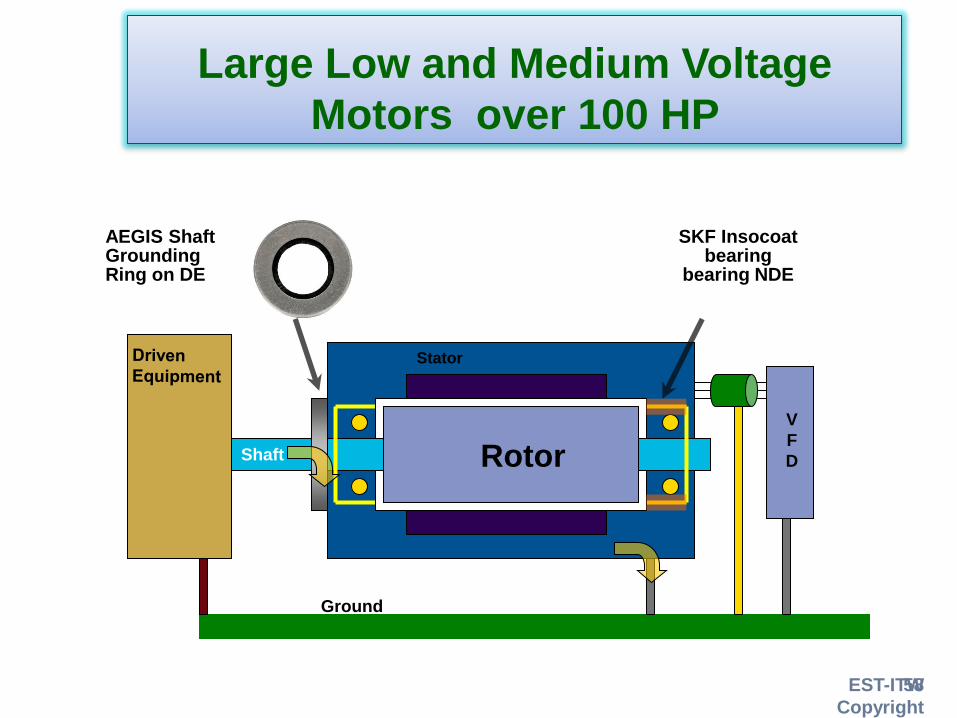
58
Large Low and Medium Voltage
Motors over 100 HP
Stator
Rotor Shaft
Ground
V
F
D
SKF Insocoat bearing
bearing NDE
AEGIS Shaft Grounding Ring on DE

MOTOR PROBLEMS
One possible fix.

MOTOR PROBLEMS
TRY GOOD HIGH FREQUENCY GROUNDING
TECHNIQUES

MOTOR PROBLEMS
OTHER WAYS TO CORRECT THE PROBLEM
FARADAY SHIELDED
MOTOR INSULATED BEARINGS

MOTOR PROBLEMS
SHAFT GROUNDING SYSTEM OUTPUT FILTERS

The number one killer of electric
motors is heat. Motors that run on
variable frequency drives run hotter
than motors that run across the line.

Voltage spikes can cause problems.
Some drive manufactures are better
at suppressing the spikes than
others.

Premium efficient motors run cooler
than standard general purpose
motors

The Motor Won’t Run in Bypass
•IS THERE POWER TO
THE BYPASS?
•SAFETY
INTERLOCK?
•OVERLOAD?
START/STOP

If the Drive Blows Power Fuses • Before plugging in another fuse ...
• With power off, use the ohmmeter to check for input AND output shorts – Line-to-bus and motor-to-bus, is desirable.
– Line-to-line if the bus connections aren’t readily available

Check programing Example: Trane TR-200 Series Start-Up
1. Parameter 1-03, TORQUE CHARACTERISTICS (For single motor
applications factory default is ok - AUTO ENERGY OPTIMUM. VT. For
multiple motors change to VARIABLE TORQUE.)
2. Parameter 1-20 kW or 1-21 HP, MOTOR POWER parameter 0-03 will
determine if parameter 1-20 –OR- parameter 1-21 is accessible, other
parameter is hidden
3. Parameter 1-22, MOTOR VOLTAGE
4. Parameter 1-23, MOTOR FREQUENCY
5. Parameter 1-24, MOTOR CURRENT
6. Parameter 1-25, MOTOR SPEED
7. Parameter 1-29, run AUTOMATIC MOTOR ADAPTATION

Start-Up Continued
1. Parameter 4-12, MIN. FREQUENCY (6Hz for fans, 18Hz for pumps)
2. Parameter 4-14, MAX. FREQUENCY (typically set to 60Hz)
3. Parameter 3-41, RAMP 1 UP TIME (60 sec for fans, 10 sec for pumps
4. Parameter 3-42, RAMP 1 DOWN TIME (60 sec for fans, 10 sec for pumps)
5. Parameter 5-12, COAST INVERSE (sets function of Terminal 27 – set to
NO OPERATION if external signal not required)

Drive Layout
Input PWR
Quality
Output


Period, range of q Diode Pair in conduction
30o to 90o D1 and D6
90o to 150o D1 and D2
150o to 210o D2 and D3
210o to 270o D3 and D4
270o to 330o D4 and D5
330o to 360o and 0o to 30o D5 and D6


Magic Component's
• Regulator
– Electronic controls
– Filters
– Lots of Magic in the boxes which in realty is just
electronics switching between 0 and 1.


Trane TR200 Variable Frequency Drive ‹#›

• Silicon diode = 0.7v
Schottky diode =
0.3v
Germanium diode =
0.2v
Typical Schottky metals: Ti, Ni, Au, Pt, Pd


PWM Drive: Diode Bridge Rectifier
DCAC Rectifier

PWM Drive Output Waveform
low speed
high speedTime frame and Pulse width controlled by Microprocessor

Types of PWM Drives
• Drives using bipolar transistors use a low carrier
frequency
(1 to 4 kHz).
• Drives Using IGBTs:
– Can use carrier frequencies greater than 10 kHz.
– Some can be switched to use lower carrier frequencies.

TR200 Layout

Input/output Testing
DC buss +
DC buss -

DC Buss Voltage Test
• DC Buss + to DC Buss –
– Input Voltage X1.3 = Minimum at Full load
– Input Voltage X 1.4 = Maximum Full load voltage

VFD Voltage
• A-B, B-C, C-A = Line Imbalance: ± 3%
• U-V, V-W, W-U= Balanced

BASIC ELECTRONIC TROUBLESHOOTING
• Ohm checking the power semiconductors.
• Ohm checking the gate driver circuits.
• Checking the gate driver circuits with a scope.
• Running the motor in hand mode.

Ohm checking the power semiconductors.
Set the ohm meter on either the diode check scale or the 2K
scale if you are using a standard LCD style meter with a 9
volt battery.
Start the process by placing the positive lead of the ohm
meter on the positive bus and then check each input
connection with the negative lead of the ohm meter noting
the value of the reading on each input line connection.

Ohm checking the power semiconductors.
NOTE: When ohm checking the power semiconductors
bus cap charging may be noticed. Do not be alarmed.
This is normal.
Now the ohm meter leads and repeat the process.
Again note the readings. What should be observed if
the power semiconductors are good, is that you will
notice that in one direction the meter readings will be
with in the range of 0.3 to 0.7 K ohms and out of scale in
the opposite direction.

Ohm checking the power semiconductors.
Repeat the same process to check the output
semiconductors. Similar reading should be obtained with
these devices.
With these reading available, determine if the drive has
sustained semiconductor damage and take the appropriate
steps to repair the drive.

Input Testing Meter set to diode test
• Meter + Lead to DC Buss +
– Meter – to L1 ,L2, L3 ≈ ∞ (infinity) (After Charge Cap.)
• Meter - Lead to DC Buss +
– Meter + to L1, L2, L3 ≈ .48
• Meter + Lead to DC Buss –
– Meter – lead to L1, L2, L3 ≈.48
• Meter – lead to DC –
– Meter + lead to L1, L2 L3 ≈ ∞ (infinity) (After Charge Cap.)

Checking the gate driver circuits with a scope.
For those people who have access to an oscilloscope,
below is the scope pattern you will see.
This measurement is only available to you with drives
sized 15 through 75 HP 460 Volt and 5 though 25 HP 208
Volt. Drives smaller and larger do not have access to
the IGBT gate leads.

Drive Layout Input PWR
Quality
Output

• An inductor stores energy in the magnetic field
created by the current.
• When the current through a coil changes and an
induced voltage is created as a result of the changing
magnetic field, the direction of the induced voltage is
such that it always opposes the change in current.
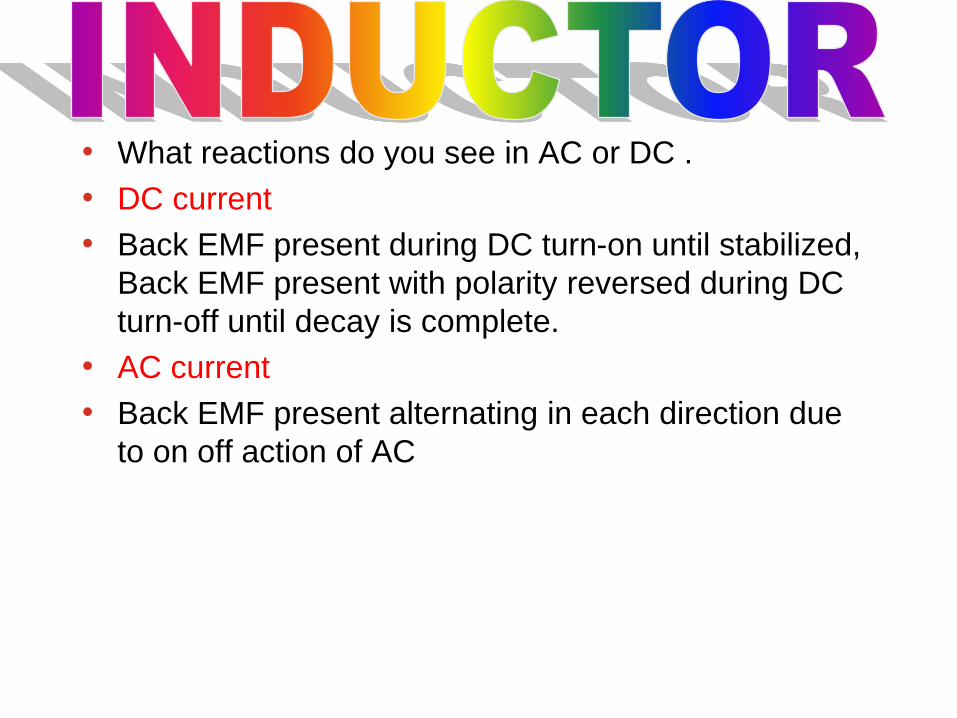
• What reactions do you see in AC or DC .
• DC current
• Back EMF present during DC turn-on until stabilized,
Back EMF present with polarity reversed during DC
turn-off until decay is complete.
• AC current
• Back EMF present alternating in each direction due
to on off action of AC

Inductor Applications
• Coils resist rapid changes in the current flowing
through them.
• Inductors freely pass steady dc current.


Reducing Harmonic Distortion
• DC link reactor
• AC line reactors

DC Link Reactors

AC Line Reactors
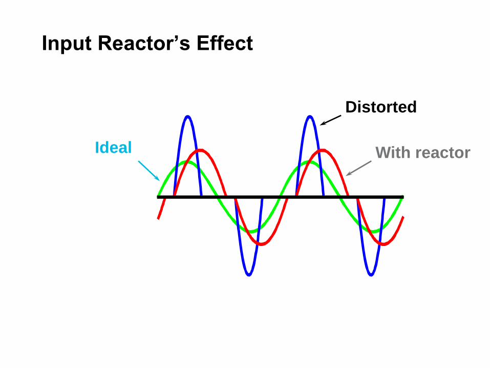
Input Reactor’s Effect
Ideal
Distorted
With reactor

Comparison
DC Link Reactors
• Reduces harmonic
distortion
• Built into the drive as
standard
• Requires one or two
coils, can reduce the
size of the bus
capacitor
AC Line Reactors
• Reduces harmonic
distortion
• Extra cost option —
increases the drive’s
size
• Requires three coils

Comparison, continued
DC Link Reactors
• Does not affect the drive’s AC line operating range
• Protects against current surges
• Voltage snubbers in the drive protect against voltage surges
AC Line Reactors
• Reduces the AC voltage supplied to the drive
• Protects against current surges
• Protects against voltage surges

AC Line Reactors
• Drives with no DC link reactors generally require AC
line reactors
– To reduce harmonic distortion
– More importantly, to keep the drive from being
damaged by power line disturbances

Combining DC and AC Reactors
• Why not combine both?
• Typical example: (from drivesmag.com) – no reactors
62% current distortion
– 3% AC reactor 37% current distortion
– 3% DC reactor 31% current distortion
– 3% DC reactor + 3% AC reactor 28% current distortion
This isn’t
cost
effective!

Reducing Harmonic Distortion
• DC link reactor
• AC line reactors
• Harmonic traps
• 12-pulse input
• Active filters

Harmonic Traps
• Designed to “trap”
specific harmonic
• Specially designed
for the individual
building
• Often applied once,
at the point of
common coupling of
all building power

D-Y transformer
to the rest of the drive
12-Pulse Input
• Eliminates the 5th and 7th harmonics
• Needs a D-Y transformer and two rectifiers
• The transformer – is expensive
– probably isn’t supplied by the drive manufacturer

Active Filter
• How it works
– Electronically monitors the AC power line
– Switches power from or to the line based on the
line’s condition
• Concerns
– Expensive
– Complex
– Adds high frequency noise (EMI and RFI) to the
building

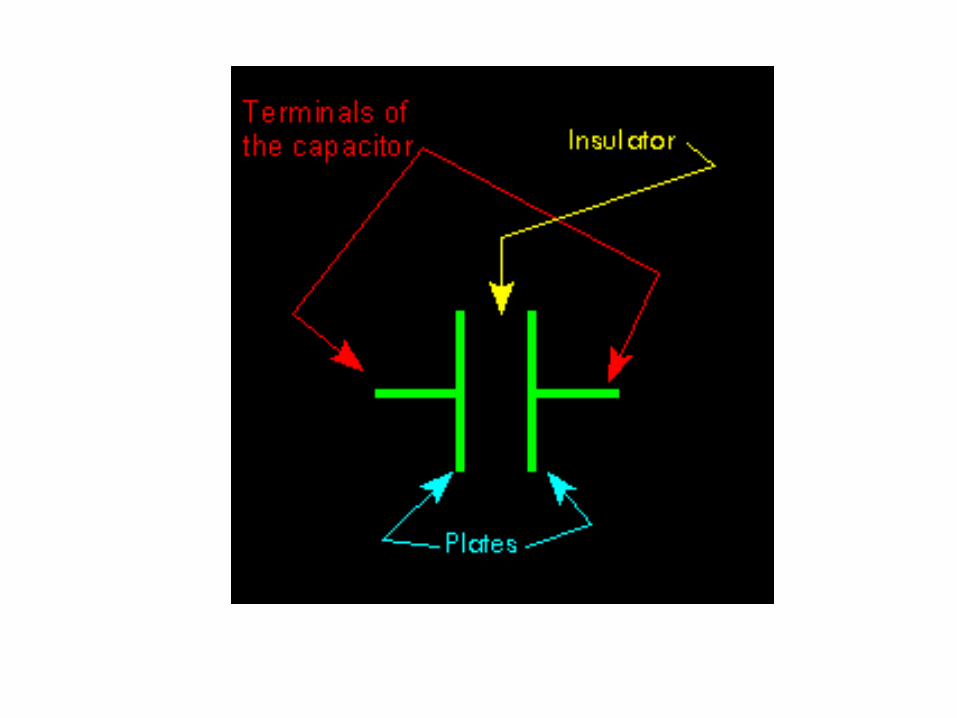

Capacitors Pass
A.C.
Capacitors
Block D.C.


CAPACITOR
A capacitor is an electronic device which consists of
two plates separated by some type of insulator. A
capacitor's value is commonly referred to in
microfarads, one millionth of a farad. It is expressed in
micro farads because the farad is such a large value of
capacitance.
When a DC voltage source is applied to the capacitor there is an initial
surge of current, then the current stops. When the current stops flowing,
the capacitor is in a charged state. If the DC source is removed from the
capacitor, the capacitor will retain a voltage across its terminals. This
charge can be discharged by connecting the plates together. Generally, if
an AC voltage source is connected across the capacitor, the current will
flow through the capacitor until the source is removed. The exceptions
to the situation, where an AC voltage is applied to a capacitor, are going
to be explained later.

Capacitors How much is it???
• Parallel Circuit
• Ct=C1+C2
• Series Circuits
• For 2 Capacitors Ct=(C1xC2)/(C1+C2)
• For more than 2 capacitors in series
• Ct=(1)/((1/C1)+(1/C2)+(1/C3))etc.

Capacitor Applications
• Power supply filters
• Spike Remover
• AC-DC Selective filter
• A Capacitor will pass the Fluctuation signal and
completely block the steady DC level.

• DC BUSS CAPACITORS:
THE GOOD, THE BAD, AND THE UGLY!

Drive Layout Input PWR
Quality
Output


The bipolar junction transistor consists of three layers
of highly purified silicon (or germanium) to which small
amounts of boron (p-type) or phosphorus (n-type) have
been added. The boundary between each layer forms a
junction, which only allows current to flow from p to n.
Connections to each layer are made by evaporating
aluminum on the surface; the silicon dioxide coating
protects the nonmetalized areas. A small current
through the base-emitter junction causes a current 10
to 1000 times larger to flow between the collector and
emitter. (The arrows show a positive current; the
names of layers should not be taken literally.) The
many uses of the junction transistor, from sensitive
electronic detectors to powerful hi-fi amplifiers, all
depend on this current amplification.
© Microsoft Corporation. All Rights Reserved.
"Bipolar Junction Transistors," Microsoft®
Encarta® Encyclopedia 99. © 1993-1998 Microsoft
Corporation. All rights reserved.


IGBT
• There are 2 Count them 2
IGBT’S In Each module used
in our VFD’s


Input/output test
• Setup
– Test for no input/output or DC bus voltage.
– Input and output drive wiring disconnected
– Set meter to Diode function
– Find Test Points (DC+, DC-, L1,L2,L3, U,V,W)

Input Testing
• Meter + Lead to DC Buss +
– Meter – to U, V, W ≈ ∞ (infinity) (After Charge Cap.)
• Meter - Lead to DC Buss +
– Meter – to U,V, W ≈ .39
• Meter + lead to DC Buss –
– Meter – Lead to U, V, W ≈ .39
• Meter – Lead to DC Buss –
– Meter + lead U, V, W ≈ ∞ (infinity) (After Charge Cap.)

Input Testing
• Meter + Lead to DC Buss -
– Meter – to L1 – L3 ≈.48
– Meter – to U – V ≈ .39
• Meter - Lead to DC Buss –
– Meter – to L1, L2, L3 ≈ ∞ (infinity) (After Charge Cap.)
– Meter – to U,V, W ≈ ∞ (infinity) (After Charge Cap.)

VFD Voltage
• A-B, B-C, C-A = Line Imbalance: ± 3%
• U-V, V-W, W-U= Balanced

Drive Control

Control
• Communication protocols
• Inputs and outputs
– Binary or digital AC or DC example: (0-24VDC, open
or closed)
– Analog example: (4-20 ma 0-10 VDC, 0-5 VDC)

OPTO-COUPLER

EEPROM Electrically erasable programmable ROM
With normal ROMs you have to replace the chip (or
chips) when new BIOS instructions are introduced.
With EEPROMs, a program tells the chip's controller
to give it electronic amnesia and then downloads the
new BIOS code into it. This means a manufacturer
can easily distribute BIOS updates on floppy, for
instance. This feature is also called flash BIOS, and
you might also come across it in devices like
modems and graphics/video cards.

Checking the gate driver circuits with a scope.
For those people who have access to an oscilloscope, below is
the scope pattern you will see.
This measurement is only available to you with drives sized 15
through 75 HP 460 Volt and 5 though 25 HP 208 Volt. Drives
smaller and larger do not have access to the IGBT gate leads.

Safety Stop

TR-200
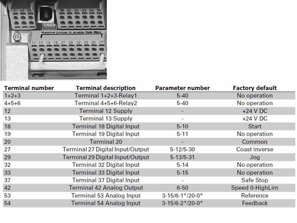

Fault Relay
240 V AC, 2 A
Analog
Inputs and
Outputs
Digital Inputs
12 & 18: Run Command
12 & 27: Interlock
(MUST be Connected to 24
V supply)
RS-485
Run Relay
30 V AC, 1 A
Wiring the Drive
• Control Wiring
• Terminal blocks
can be unplugged

Digital Inputs:
12 & 27: Interlock
(MUST be Connected to
24 V supply)
Wiring the Drive
• Control Wiring
• Terminal
blocks can be
unplugged
Plus 24 VDC
Safety Contact
Fire / Freeze / Etc.
Parameter 304 ( Coast Inverse)
Display reads “UN READY” in
lower right corner.

Digital Inputs:
12 & 18 (Start / Stop)
(MUST be Connected to
24 V supply)
Wiring the Drive
• Control Wiring
• Terminal
blocks can be
unplugged
Plus 24 VDC
Start Command From Automation
Parameter 302 ( Start )
Note: When Contact Opens Unit Ramps to a Stop

Wiring the Drive
• Control Wiring
• Terminal
blocks can be
unplugged
Drive Fault Indication
Use Terminals 01 and 03
Registers a Drive Fault if not Powered up
Terminal Block Located under Power Terminals
Drive Run Indication
Contacts are Low Voltage ( 30 VAC)
Signals Automation Drive is Running
Parameter 326
(No Alarm)
Parameter 323
(Running)

Wiring the Drive
• Control Wiring
• Terminal
blocks can be
unplugged
Positive Voltage scaled 0 to 10 VDC
Analog Input 53
Para 308 ( Reference)
Para 309 (Low Scaling) 0 VDC
Para 310 ( High Scaling) 10 VDC
Common for Input Follower Signal
Para 314
Terminal 60 Function set for (No Operation)
FROM AUTOMATION

Trane TR200 Variable Frequency Drive ‹#›
Analog Inputs Term 530-10 V
Term 540-10 V
Term 604-20 mA
FUNCTION * 308 311 314
SCALE LOW 309 312 315
SCALE HIGH 310 313 316
* Set the FUNCTION of the terminal used for speed
control to REFERENCE.
Set the FUNCTION of unused terminals to NO
OPERATION.
Open Loop
Note: All Trane drives have term 53 set for
default as Reference & 0-10 VDC

VFD testing

By Pass Contactors


