transceiver troubleshooting for idiots...
TRANSCRIPT
© 2020 John H DeRosa - [email protected] - http://aviation.derosaweb.net/presentations 1
Transceiver
For Idiots /
“Made
Troubleshooting
Dummies
Easier”
This document may have been updated
Be sure to download the latest version!
Issue Date: April 2, 2020

© 2020 John H DeRosa - [email protected] - http://aviation.derosaweb.net/presentations 2
This document may have been updated with new
information, changes, or corrections.
Be sure to visit my presentation web site and
download the latest version of this document. It could
make an important difference in your work!
http://aviation.derosaweb.net/presentations
Thank you, John
PLEASE NOTE

© 2020 John H DeRosa - [email protected] - http://aviation.derosaweb.net/presentations
Troubleshooting aircraft transceiver issues can be difficult,
time consuming and irksome to resolve!
Especially if the issues are intermittent!
I hope that these notes may help you to identify your issue.
Once identified you may be able to fix the problem yourself,
or you may find you need to engage some professional help.
Take it one step at a time!
Best of Luck!
3

© 2020 John H DeRosa - [email protected] - http://aviation.derosaweb.net/presentations
Table of Contents
4
• Typical Glider Transceiver Connections
• Troubleshooting Steps by Symptom
• Troubleshooting Steps - Miscellaneous
• Solving Transceiver Interference
• Issues with Microphones
• Antennas & Coax Cables• Antenna Types
• Coax Cables, BNC Connectors Troubleshooting
• Antenna System “VSWR” Testing
• Schematics and Misc Information• Speaker/Microphone Boxes
• Headset Jacks and Plugs
• Transceiver Repair Stations

© 2020 John H DeRosa - [email protected] - http://aviation.derosaweb.net/presentations
Typical Glider Transceiver Connections
5
Glider’s Antenna
(Receive & Transmit)
Battery
Power
Source
Microphone
(Audio Input)
Speaker
(Audio Output)
Push to Talk
Switch
Coaxial
Cable

© 2020 John H DeRosa - [email protected] - http://aviation.derosaweb.net/presentations
Troubleshooting Steps By Symptom1. No Power
Transceiver getting power and “lighting up”? Battery dead? Bad fuse or tripped breaker?
Inspect connections/wiring on the rear of the radio (control, power, antenna). Wiggle the connector –
does that help? Is the connector inserted fully? Do you see any broken/loose wires?
2. No Audio Received From Others Tuned to the correct frequency? Are you a quarter-kilohertz (0.25khz) off?
Volume turned up high enough?
Squelch set properly? Try un-squelching 100%. Do you hear a “shhh” sound or received signal?
Check the battery voltage at the battery and at the radio. Should be 12VDC or more.
3. No Transmit Audio Heard by Others Push to talk (PTT) switch broken or intermittent. Confirm that the radio is “keying”. Almost always
there is an indicator of some sort on the transceiver’s front panel to indicate you are keyed and
transmitting.
Is there “carrier” but no audio received? That is, can your helper tell that you have keyed your
transceiver but no audio is heard? Might be a bad or disconnected microphone (see following slides).
Battery Issues
Swap your battery with known good battery and retest.
Use a voltmeter to measure the battery voltage when the transceiver is on and then during transmit.
If there is excessive battery voltage drop (greater than 2Vdc) there could be a bad antenna (see next item).
Antenna Issues - Remove the aircraft’s antenna coax/BNC cable/connector and temporarily replace it
with a portable handheld “Rubber Ducky” antenna. If transmit audio is working properly with a
different antenna then this points to the ship’s antenna, coax or BNC connector as the culprit.
6
© 2020 John H DeRosa - [email protected] - http://aviation.derosaweb.net/presentations
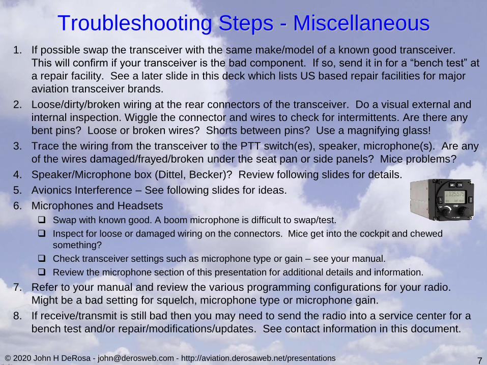
1. If possible swap the transceiver with the same make/model of a known good transceiver.
This will confirm if your transceiver is the bad component. If so, send it in for a “bench test” at
a repair facility. See a later slide in this deck which lists US based repair facilities for major
aviation transceiver brands.
2. Loose/dirty/broken wiring at the rear connectors of the transceiver. Do a visual external and
internal inspection. Wiggle the connector and wires to check for intermittents. Are there any
bent pins? Loose or broken wires? Shorts between pins? Use a magnifying glass!
3. Trace the wiring from the transceiver to the PTT switch(es), speaker, microphone(s). Are any
of the wires damaged/frayed/broken under the seat pan or side panels? Mice problems?
4. Speaker/Microphone box (Dittel, Becker)? Review following slides for details.
5. Avionics Interference – See following slides for ideas.
6. Microphones and Headsets
Swap with known good. A boom microphone is difficult to swap/test.
Inspect for loose or damaged wiring on the connectors. Mice get into the cockpit and chewed
something?
Check transceiver settings such as microphone type or gain – see your manual.
Review the microphone section of this presentation for additional details and information.
7. Refer to your manual and review the various programming configurations for your radio.
Might be a bad setting for squelch, microphone type or microphone gain.
8. If receive/transmit is still bad then you may need to send the radio into a service center for a
bench test and/or repair/modifications/updates. See contact information in this document.
7
Troubleshooting Steps - Miscellaneous

© 2020 John H DeRosa - [email protected] - http://aviation.derosaweb.net/presentations
Issues with Microphones (Types) There are two types of microphones - “standard” (electret) and “dynamic”.
Most modern transceivers can utilize either microphone type but If your microphone is
not connected to the transceiver correctly then it may have must either be much lower
audio output, no audio output at all, or distorted audio.
There are two ways that transceivers are set up for particular microphone type:1. The microphone is connected to a different pin (and mic ground*) on the transceiver’s connector.
2. The microphone is connected to a single input pin (and mic ground*) on the transceiver’s connector and then
the type is set using a software setting.
Refer to your owner‘s manual.
NOTE: Some older transceivers may only accept one type of microphone.
See your transceiver’s manual for details on making connections and proper settings.
Different microphone types favored by specific manufacturers:
8
“Dynamic” Microphones Peiker TM170
Dittel
Becker
f.u.n.k.e.
“Standard” Microphones Microair
Peiker ME510 & TM168
XCOM
Mikrosmart
* On most transceivers there is a specific “microphone” ground pin which is different than the battery or PTT ground pin(s).

© 2020 John H DeRosa - [email protected] - http://aviation.derosaweb.net/presentations
Issues with Microphones (Gain)
Another issue can be microphone audio gain (amplification).
This gain may need to be adjusted for clear and strong transmission audio. In all
transceivers there is a way to adjust this gain. Sometimes the gain adjustment is a screwdriver setting through the side of the case.
Other times microphone gain is made with a software adjustment through menu settings via the front panel
knobs.
See your transceiver’s manual for specific details.
Adjust the gain one step at a time and retest your transmissions. Too small of microphone gain will give low, or no, audio transmission.
Too large of microphone gain can distort your audio transmission.
9

© 2020 John H DeRosa - [email protected] - http://aviation.derosaweb.net/presentations 10
Because all avionics devices are connected together via their power and ground
cabling, one avionics device can send interference to your transceiver through the
power cabling and heard in your transmissions.
By powering down one device at a time you can help determine which one is
causing your interference.
Solving Transceiver Interference (Power)
1. Verify that all ground cables are connected to a common
ground bus (stud or bar). This prevents interference from
“ground loops”.
2. Route the power and ground cabling of the offending avionics
devices through individual “ferrite rings” sometimes called
“chokes”,“beads” or “cores” (shown at right). These are
inexpensive small split devices that are easy to clip onto
existing wires. These rings can block transients and
interference from traveling along the power/ground leads from
one device to another. Start with your transceiver’s power
leads then re-test. Move onto your other device’s power and
ground wires if needed.
© 2020 John H DeRosa - [email protected] - http://aviation.derosaweb.net/presentations
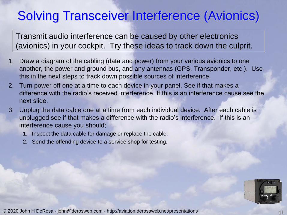
1. Draw a diagram of the cabling (data and power) from your various avionics to one
another, the power and ground bus, and any antennas (GPS, Transponder, etc.). Use
this in the next steps to track down possible sources of interference.
2. Turn power off one at a time to each device in your panel. See if that makes a
difference with the radio’s received interference. If this is an interference cause see the
next slide.
3. Unplug the data cable one at a time from each individual device. After each cable is
unplugged see if that makes a difference with the radio’s interference. If this is an
interference cause you should;
1. Inspect the data cable for damage or replace the cable.
2. Send the offending device to a service shop for testing.
11
Solving Transceiver Interference (Avionics)
Transmit audio interference can be caused by other electronics
(avionics) in your cockpit. Try these ideas to track down the culprit.

© 2020 John H DeRosa - [email protected] - http://aviation.derosaweb.net/presentations
Antennas &
Coax Cables
13

© 2020 John H DeRosa - [email protected] - http://aviation.derosaweb.net/presentations
Imbedded Tail Antenna
[Used on Non-metallic Gliders]
Antenna Types[and typical use]
Rubber “Duckie” Antenna
[Used on Portables]
Flexible Magnetic Antenna
[Used on Base Stations]
Steel Antenna
[used on metallic aircraft]
Insulator
14

© 2020 John H DeRosa - [email protected] - http://aviation.derosaweb.net/presentations
Common Radio Frequency (RF)
Coaxial Connector Types•BNC – Typically used to connect an antenna to an aircraft
transceivers (“radio”). • Connection Type: Quarter-turn
• Coax Attachment Difficulty: Fairly Easy
•TNC – Typically used to connect an antenna to a transponder. • Connection Type: Threaded
• Coax Attachment Difficulty: Fairly Easy
•SMA – Found on most GPS antennas. Also found on the
antennas for FLARM devices. There are also “reverse
polarity” varieties known as SMA-RP. • Connection Type: Threaded
• Coax Attachment Difficulty: Hard
•MCX - Found on some GPS antennas such as for FLARM
devices. • Connection Type: Push-on
• Coax Attachment Difficulty: Hard
15
NOTE: All connectors shown are male. There are female versions for each type.

© 2020 John H DeRosa - [email protected] - http://aviation.derosaweb.net/presentations
Antennas, Coax Cables, BNC Connectors
Troubleshooting1. In the vast majority of situations the antenna coax should be RG-58 (50Ω)
2. Inspect the coax BNC connection at the transceiver for broken center pin,
loose coax, poor/broken/frayed/shorted ground shield. a) See the next several pages for details.
3. Inspect the coax connection at the antenna for loose/broken connections.
4. Inspect the coax leading to the antenna if accessible for breaks or dents.
5. Inspect/replace the antenna itself if accessible.
6. Replace the antenna with a “rubber duckie” antenna and retest.
7. Measure the battery during transmit looking for large drops in the voltage
(2Vdc or more).
8. Use a VSWR meter to verify your entire antenna system (transceiver, BNC
connector(s), coax and antenna). See details in a later slide.
17

© 2020 John H DeRosa - [email protected] - http://aviation.derosaweb.net/presentations 18
BNC ConnectorsMicroaire recommends using only soldered or crimped BNC connectors
Ferrule ContactBody
Crimp Ferrule HereCrimp or Solder Here
Stripping Coax
Step 1 Step 2
Step 3
BNC = Bayonet Neill-Concelman)
Coax Crimping Tool
$15-$25
Shield
Shield
Solderless/Crimpless/Screw-on BNC connectors are NOT
recommended! Their performance is considered substandard!

© 2020 John H DeRosa - [email protected] - http://aviation.derosaweb.net/presentations 19
From the Microair M760 Instruction Manual
Coax - Use 50Ω (ohm) RG-58 cable. When the coax cable
length exceeds ~15m/~45 feet (uncommon in gliders) then
RG-213 (low loss) cable should be used. The actual
length of the installed coax is unimportant*!
Antennas - May be ¼ wave whip (23.95”/61cm for
123.3Mhz) or ½ wavelength dipole.
Antennas & Coaxes
* See https://www.ad5gg.com/2017/06/11/coaxial-cable-length-does-not-change-swr/

© 2020 John H DeRosa - [email protected] - http://aviation.derosaweb.net/presentations 20
A VSWR* meter is a handy tool for technical folks to test the entire antenna system of
the coax and antenna end to end plus transceiver performance.
This meter will measure how well the various antenna system components (e.g.
transceiver, BNC connectors, coax wiring, and antenna) are working together for best
performance. Any one of these components can cause transmit issues. Especially
suspect are the BNC connectors. Rarely is the antenna the issue.
Simply said, during transmit the meter will indicate if things are not optimum by
indicating a higher than normal (numerical) VSWR reading. A reading of 1.0 is absolutely
“perfect” (and basically impossible). VSWR between1.0 and 3.0 is good. Beyond that
something is wrong with your antenna system.
An easily testable result of having a faulty antenna system is when the transceiver is
drawing much more current than usual. This can be noticed by measuring the battery
voltage which will droop significantly from the normal ~12Vdc down to ~10Vdc or lower.
The use, and types, of VSWR meters are shown in the following slides.
Antenna System “VSWR” Testing
* VSWR stands for Voltage Standing Wave Ratio which is expressed as a value [colon] 1 (e.g. 1.3:1)
https://en.wikipedia.org/wiki/Standing_wave_ratio

© 2020 John H DeRosa - [email protected] - http://aviation.derosaweb.net/presentations 21
Antenna System “VSWR” TestingExamples of Types of VSWR Meters
Meter Cost: Anywhere from $20 to hundreds of dollars
Sources: eBay, Amazon, Ham Radio equipment sites
Required Accessories: Short length of coax, BNC adapters
VSWR/Power/Frequency Meter
Surecom SW102
Inexpensive VSWR/Power Meter Professional VSWR Meter
BIRD FA-8141A
How To Use Video: https://www.youtube.com/watch?v=qSea5FjcTDE
Astatic PDC1
Be sure to buy a meter that covers the
aviation frequency band of 118-137 MHz

© 2020 John H DeRosa - [email protected] - http://aviation.derosaweb.net/presentations 22
Antenna System “VSWR” TestingTypical VSWR Test Setup
Glider’s
Transceiver’s
BNC Connector
BNC to BNC
Coax Patch Cable
BNC to N-Type
Or
BNC to PL-259
AdapterVSWR Meter May Have
N or PL connectors
Glider’s Antenna’s
Coax BNC
Glider’s Antenna
Total Cost of Test Equipment: Approximately $100
Testing Process:
1) Unplug the glider’s antenna coax from the
rear of the transceiver.
2) Interconnect the equipment as shown below.
3) Press the PTT switch on the transceiver.
4) Monitor the VSWR reading on the meter.
VSWR Measuring Instrumentation
N-Type to BNC
Or
PL-259 to BNC
Adapter

© 2020 John H DeRosa - [email protected] - http://aviation.derosaweb.net/presentations
Miscellaneous
Information
23
Speaker
Boxes
Stereo Headphone Jack
Audio (Left)
Audio (Right)Audio Low
Headset
Wiring

© 2020 John H DeRosa - [email protected] - http://aviation.derosaweb.net/presentations
1. Move the microphone plug to the other jack (or reverse the
connections if there are two microphones)*.
2. Wiggle the microphone connector(s) and cabling to see if they are
loose. Do that while trying to transmit to see if things work
(possibly intermittently).
3. Check the microphone’s (male) plug. Are there any bent pins?
Loose or broken wires? Shorts between pins? Displaced?
4. Check the box’s microphone(s) (female) jacks. Pins seem in place?
Not broken or pushed into the connector?
5. Unmount the speaker box and look inside. Are there any bent pins?
Loose or broken wires? Shorts between pins? Wiggle things
around! Do that while trying to transmit to see if things work
(possibly intermittently).
6. Perform a continuity check of the wires going from the box to the
transceiver’s (rear) connector.
24
Speaker/Microphone Boxes
* Note that the microphone jacks/plugs are not interchangeable between Dittel/Filser and Becker speaker
boxes even through the connections are both considered “DIN-5” types. The Becker/Filser connectors
have 45º pin spacing while the Dittel connectors have 60º pin spacing. Argggg!
Becker/Filser 45º Dittel 60º
Dittel
Becker/Filser
If there is a Becker/Filser or Dittel speaker box installed in the glider then try these things;
Becker/Filser and Dittel box schematics are shown on the next few slides

© 2020 John H DeRosa - [email protected] - http://aviation.derosaweb.net/presentations 25
Soldered
terminals for
wiring to the
Transceiver
(Pins B to H)
Screw
terminals to
the PTT Switch
Microphone
Jacks
Microphone
Jacks & WiringInternal
Speaker
Becker 1PL042 (Filser BS 4/8)
Internal View
Becker/Filser 45º
Din-5 Connectors

© 2020 John H DeRosa - [email protected] - http://aviation.derosaweb.net/presentations 26
Full Becker AR4201 Manual with Wiring Diagrams Available At:
https://www.cumulus-soaring.com/becker/AR4201-Manual.pdf
See details on
next page
Becker 1PL042 (Filser BS 4/8) - Schematic
Becker/Filser 45º
Din-5 Connector

© 2020 John H DeRosa - [email protected] - http://aviation.derosaweb.net/presentations 27
Screw terminals to
the PTT Switch
Soldered
terminals for
wiring to the
Transceiver
(Pins B to H)
Microphone #2 Jack
(with details)
Microphone #1 Jack
Becker 1PL042 (Filser BS 4/8) – Schematic (Details)

© 2020 John H DeRosa - [email protected] - http://aviation.derosaweb.net/presentations 28
“FASTON”
terminals for
wiring to the
Transceiver
Quick
Release
terminals to
the PTT
Switch
Microphone
Connectors
Microphone
Jacks & Wiring
Internal
Speaker
Dittel F10061 Speaker Box
Internal View
Dittel 60º
Din-5 Connectors

© 2020 John H DeRosa - [email protected] - http://aviation.derosaweb.net/presentations 29
Dittel F10061
Speaker Box
Full Dittel FSG71 Manual with Wiring Diagrams Available At:
https://www.cumulus-soaring.com/dittel/FSG%2070-FSG71M%20Operation%20and%20Installation%20Manual.pdf
Microphone #2 Jack
Microphone #1 Jack
(with details)
Dittel F10061 Speaker Box - Schematic“FASTON” connections for
wiring to the Transceiver
Dittel 60º
Din-5 Connector

© 2020 John H DeRosa - [email protected] - http://aviation.derosaweb.net/presentations
Headset Jacks and PlugsHeadsets are not very common in gliders. However, their jacks and
plugs may be used and might be troublesome for several reasons usually
as simple as a broken wire or corroded contact in the jack. The plugs are
usually less of an issue.
• IMPORTANT: There are two different sizes of headset jacks and plugs
depending on their function;
• Microphone and PTT – 0.205” ID - JJ-033 (3-conductor)
• Phones (Ear pieces) – 0.250” ID - JJ-034 (2-conductor)
30

© 2020 John H DeRosa - [email protected] - http://aviation.derosaweb.net/presentations
Headset Plug Wiring(Headphone Earpiece Audio)
31

© 2020 John H DeRosa - [email protected] - http://aviation.derosaweb.net/presentations
Headset Plug Wiring(Microphone and Push to Talk)
32

© 2020 John H DeRosa - [email protected] - http://aviation.derosaweb.net/presentations
Anatomy of a Headset Plug(Tip/Ring/Sleeve)
33

© 2020 John H DeRosa - [email protected] - http://aviation.derosaweb.net/presentations
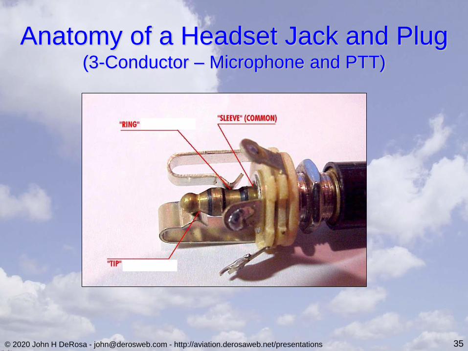
Headset Jack Wiring
• Headset (mono)Tip – Earpiece/Speaker High
Sleeve – Earpiece/Speaker Low
• Microphone and Push-to-Talk (PTT) SwitchTip - Push-to-Talk Switch
Ring - Microphone High
Sleeve - Microphone Low
Sleeve - Push-to-Talk Switch
Pilot Phones
Tip
Sle
eve
Pilot Mic Jack
Pilot PTT
Tip
Sle
eve
Rin
g
34
Mic/PTT Jack
0.205” ID
Phones Jack
0.250” ID
© 2020 John H DeRosa - [email protected] - http://aviation.derosaweb.net/presentations
Anatomy of a Headset Jack and Plug(3-Conductor – Microphone and PTT)
35
© 2020 John H DeRosa - [email protected] - http://aviation.derosaweb.net/presentations
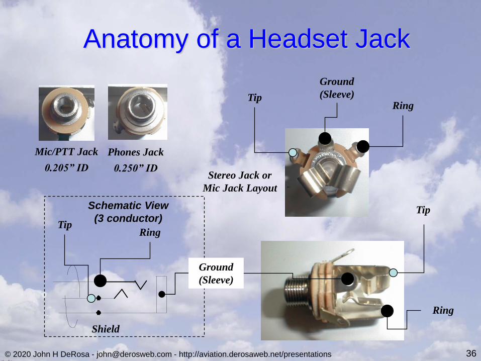
Anatomy of a Headset Jack
Mic/PTT Jack
0.205” ID
Phones Jack
0.250” IDStereo Jack or
Mic Jack Layout
Ground
(Sleeve)
Tip
Ring
TipRing
TipRing
Schematic View
(3 conductor)
Ground
(Sleeve)
Shield
36

© 2020 John H DeRosa - [email protected] - http://aviation.derosaweb.net/presentations 37
Common Transceiver Repair Stations(Based in the United States)
• Becker Avionics
• Gulf Coast Avionics Corp.
• http://www.GulfCoastAvionics.com
• 3650 Drane Field Road, Lakeland, FL 33811
• Phone: 863-709-9714
• Email: [email protected]
• Walter Dittel (f.u.n.k.e.)
• Peninsula Avionics
• http://www.peninsulaavionics.com/
• 14229 SW 127 Street, Miami, FL 33186
• Phone: 305-238-6550
• Email: [email protected]
• Microair Avionics
• MicroairUSA Service
• http://www.microairusa.com/
• 2711 Legion Rd # 8564, Erie, Pa 16505
• Phone: 814-882-2855
• Email: [email protected]

© 2020 John H DeRosa - [email protected] - http://aviation.derosaweb.net/presentations
See My Other Presentations
• Glider Electrical Wiring
• Transceiver Troubleshooting
• Oxygen Systems
• Working with Glider Air Lines
• Sailplane Wiring
• Trailer Wiring & LED Lights
• Pilot Relief Systems
• Battery Testing
38
http://aviation.derosaweb.net/presentations
• Spar Alignment Tool
• L’Hotellier Fittings
• Carbon Fiber Panels
• IGC Filename Decoding
• Blanik L-23 Strut Work
• Survival Kits
• Removing Painted Lettering
Send Me Feedback!