transferred charge: indicator for...
TRANSCRIPT

24th International Conference on Electricity Distribution Glasgow, 12-15 June 2017
Paper 0250
CIRED 2017 1/5
TRANSFERRED CHARGE: INDICATOR FOR VACUUM APPLICABILITY
Martin LEUSENKAMP Gerard SCHOONENBERG Eaton – China Eaton – The Netherlands [email protected] [email protected]
ABSTRACT
A determining indication for contact wear of a Vacuum
Interrupter (VI) is the cumulative transferred charge
(Qcum), during the time between separation of the
contacts, and the moment that the current is interrupted.
The corresponding contact wear can be expressed in net
loss of contact material (in µg/A·s or µm/A·s). Standard
Vacuum Circuit-Breakers (VCB’s) have a random
opening on the current wave, so the contact wear is
virtually equally distributed over both contacts at large
number of operations.
For Eaton VCB’s the total number of interruptions of
short-circuit current (Isc) is determined, based on actual
switching tests. The number of fault interruptions is
dependent on, e.g.:
• Allowed contact wear ε (standard VI: ε=3mm);
• Choice of contact material;
• Contact configuration: Butt, TMF (Transverse
Magnetic Field) or AMF (Axial Magnetic Field);
• Opening time of the VCB;
• Frequency (f) and time-constant (τ) of the network
(IEC standard is τ = 45 ms);
• RMS value of the fault current to interrupt;
• Switching angle (ϒ) of initiation of the fault current;
• Switching polarity of current (random or always
unipolar).
Besides determining the allowed total number of random
interruptions as function of the symmetrical fault current,
the critical transferred charge and peak current is
determined where a VI is still able to interrupt. The
maximum values are based on certification testing. They
generally occur during the T100a O-operations
according to IEC 62271-100. Based on these maximum
values, a VCB can be reclassified for interrupting Isc for
practical situations, e.g., in networks with:
• Other time constants. Reference is made to IEC
62271-100 regarding the test T100a in the current
edition 2 (2008) and also the treatment in the
upcoming Amd.2 (17A/1118/CDV) is discussed;
• Delayed current zeroes, for faults near to
generators.
Some examples are evaluated.
INTRODUCTION
The use of Vacuum Interrupters (VI’s) is wide spread all over the world in Medium Voltage (MV, 1-52 kV) networks. VI’s are capable of withstanding Rate of Rise of Recovery Voltages (RRRV’s, after interruption of the
current) that exceed 5 kV/µs, so about 10 times more than IEC prescribes. Generally, then the only variable to check is the arc energy (I*Varc*tarc) within the VI during interruption, as this is a measure for contact wear and also the determining factor whether the VI is able to interrupt. Because the arc voltage is more or less constant, the transferred charge I*tarc is proportional to the arc-energy (see also discussion of fig.6). The allowed total contact wear during lifetime of a Vacuum Circuit Breaker (VCB) defines the maximum number of (short-circuit) currents it is able to interrupt. After explanation of the impact of the time-constant (τ) of the network and the switching angle (ϒ) of initiation of the (fault) current, the correct way of checking on fit for purpose in situations deferring from the IEC standard situations is given, including some examples. Finally the developments in IEC 62271-100 regarding the test T100a are discussed.
SHAPE OF FAULT CURRENTS
1-phase considerations:
A fault current in a MV network is highly inductive by nature. IEC 62271-100, the standard for Circuit-Breakers (CB’s) defines the standard time-constant of the network τ (=L/R) to be 45 ms, corresponding to X/R = 14,14; cos (φ)=0,071 and φ = 85,95⁰. When a fault occurs, the shape of the current is depending on the angle (ϒ) of initiation of this current, related to the voltage. In fig.1 the maximal asymmetrical current is given for a 50 Hz network with τ=45 ms. This maximal current occurs when ϒ=0. Both the current and the voltage are presented in per unit values (1 p.u. = peak of 1kA symmetrical current, so √2*1kArms, respectively peak of voltage phase value, so Ur*√2/√3).
Fig.1: Maximal asymm. current; f=50Hz, τ= 45ms
As depicted in fig.1, the asymmetrical current is built up from a symmetrical (AC) component and a declining (DC) component. The DC component starts at the same

24th International Conference on Electricity Distribution Glasgow, 12-15 June 2017
Paper 0250
CIRED 2017 2/5
value as the AC component at t=0, but of opposite sign, in order to have the total current to start at I=0. After e.g. 3*τ, the DC component has exponentially declined to less than 5% of the starting value (e-3 = 4,98%). The current would be immediately symmetrical, so without any DC component, when ϒ equals to φ (with φ=85,95⁰ for the IEC standard network). When all possible angles in respect to the voltage are considered, it shows that nodes and anti-nodes will occur in the envelope of the possible currents, see fig.2.
Fig.2: Currents for all angles ϒ; f=50Hz, τ=45ms
The location of the nodes and anti-nodes is not depending on the τ, but the amplitudes are and also the time the curve along the anti-nodes has damped out to a straight line (DC component damped out to zero for all closing angles); compare fig.2 and fig.3. In the theoretical case that R=0 in the network, so τ (=L/R) is infinite, the nodes will be 0 p.u. and the anti-nodes (peak of asymmetrical current)will be 2 p.u. without any damping.
Fig.3: as fig.2, but now τ= 210 ms
3-phase considerations:
With the knowledge from the 1-phase considerations above, it is easy to see that the moment a VCB opens its contacts is very determining regarding the size of the current loop to follow before the VCB can clear on a current zero, and therefore also regarding the transferred charge with opened contacts. A complicating factor is the 3-phase character of the short-circuit currents that can arise. When one phase clears, the short-circuit current turns into 2-phase including a phase shift, resulting in a possible enlarged current loop for a phase, see fig.4 where a major extended loop is depicted for kpp=1.5 (floating neutral). Explanation of ∆t2 and ∆ta2 is given further on under “TREATMENT T100A IN IEC 62271-100”, 2016.
Fig.4: 3-phase currents with extended major loop
after clearing in phase L2; f=50Hz, τ= 45ms
TRANSFERRED CHARGE, 3-PHASE:
IEC 62271-100, standard for circuit-breakers:
The IEC standard for Circuit-Breakers (CB’s), IEC 62271-100 [ref.1], defines the minimum opening time as the shortest opening time that occurs when energizing the CB with 110% of the rated auxiliary voltage. Now we define the contact separation time (ts) as the minimum opening time of the CB plus a half period (T/2) reaction time for a protection relay, in line with IEC. The moment of short-circuit is thought to appear in all 3 phases at the same moment, e.g. by closing onto a short-circuit. Also the opening of the 3 poles of the circuit-breaker can be assumed to take place at the same moment. According to IEC 62271-100 it is not needed to take into account the allowed deviations in timing of the contacts of the 3 poles.
Max transferred charge, based on IEC62271-100
With the starting points in line with IEC 62271-100, specific contact separation times ts after initiation of the short-circuit current (Isc) were investigated. For each ts, all possible angles ϒ of initiation of Isc have been searched along in 3 phase situations. The maximum transferred charge (Q-max) was determined, including the impact of a minimum arcing time. During the minimum arcing time, there is already the arc between the contacts, but the CB cannot yet clear the current when a current zero appears during this time. In fig. 5 a range of possible contact separation times ts is presented horizontally with on the vertical axis the corresponding Q-max for a 3-phase current interruption. For general use, Q-max is shown in C/kArms. For a specific Isc, the actual Q-max can then simply be found by multiplying with Isc (in kArms). It appeared that only in about 10% of the contact separation times (so also of the opening times), the fully asymmetrical current gives the highest Q-max! Fig.5 also depicts that larger minimum arcing times result in less variation in Q-max. For VCB’s up to 24 kV, the minimum arcing time will generally be 2 to 4 ms, for SF6 CB’s this can be higher (e.g. 8 ms).

24th International Conference on Electricity Distribution Glasgow, 12-15 June 2017
Paper 0250
CIRED 2017 3/5
Fig.5: Max. transferred charge at 3-phase current
interruption (f=50Hz, τ = 45ms, various t_arc-min) From fig.5 it can be concluded that every moment of contact-separation ts, in combination with the minimum arcing time of the CB, implies a specific Q-max, being the maximum value for the transferred charge. Because a mechanism of a CB will in practice never be faster than used for certification tests at 110% of auxiliary voltage, but can be slower due to relay settings, lower actual auxiliary voltage etc., the next peak of Q-max will be the absolute maximum a CB could encounter. When the separation of the contacts would take place after more than 5*τ, the DC component has practically disappeared and the current interruption will take place on a purely symmetrical Isc, with a constant max possible transferred charge of 10,3 C/kArms for t_min.arc = 2ms (10,7 for 4ms and 14,6 for 8 ms).
VI SWITCHING CHARACTERISTICS
Eaton VI’s go through an extensive series of tests prior to release. Besides, e.g., mechanical life tests, a critical test series is the assessment of the maximum fault current interruption capability and electrical life under fault current condition. As VI’s are being used in a wide range of applications and within VCB’s with different characteristics, it is not sufficient to test only at a specific current rating. To be able to reclassify a VI for use in all possible applications, like networks with non-standard frequencies f or time-constants τ, breakers with different opening times or switching (small) generators with possible associated delayed current zeroes, the critical transferred charge must be determined [ref.2] as also the total cumulative charge (Qcum) a specific interrupter type is able to switch prior to reaching the erosion limit. During the test series to establish the critical charge both the fault current as arcing times are varied and per test the transferred charge and arc-energy determined. This procedure leads to a typical curve as shown in fig. 6 where the “Normal” arcing time tarc_normal ≤ T/2+tarc_min, (T being 20ms for 50 Hz) the “Intermediate” arcing time tarc_normal < tarc_intermediate ≤ T and the “Long” arcing time tarc_long > T which is normally cleared by the test lab back-up breaker for high Isc. The minimum arcing time for a VI applied in a MV application is up to a few ms depending mainly on the peak of the Transient Recovery Voltage and initial opening speed of the VI contacts.
Fig.6: Critical transferred charge Q_critical During this test-series also the electrical life limits are being determined by plotting the contact erosion as function of the cumulative charge. The maximum cumulative charge Qcum_max is the value when the erosion limit for the specific VI has been reached. For Eaton VI’s this is typically 3mm. In fig. 7 the erosion rate for a typical TMF type VI is shown. With Qcum_max known, the number of fault interruptions for a specific current rating Isc can be determined. For example, with the average transferred charge Qav [C/kA] during a symmetrical 3-phase interruption known the number of fault interruptions prior to reaching the erosion limit can be
calculated as follows: _ max# cum
av
QIsc Isc
Q= ⋅
Fig.7: Erosion rate �=f(Qcum)
Eaton VCB’s are generally assigned for an allowed total number of 30 to 100 random interruptions of Isc. Regarding the critical charge, an ample safety factor is applied to guarantee a 100% safe operation under all circumstances and giving a very high probability of passing the most stringent certification test series when applied in a VCB. For reclassification purposes the determined critical charge of the specific interrupter type with applied safety factor should be used but normally this value is unknown to the breaker manufacturer. An alternative method for reclassification is then to use the data of the actual certified VCB and determine the maximum transferred charge switched successfully during the T100a test series. In the next paragraph examples are shown how to reclassify a VCB tested with the standard τ=45ms for use in other networks, e.g. with a τ=210ms time-constant.
24th International Conference on Electricity Distribution Glasgow, 12-15 June 2017
Paper 0250
CIRED 2017 4/5
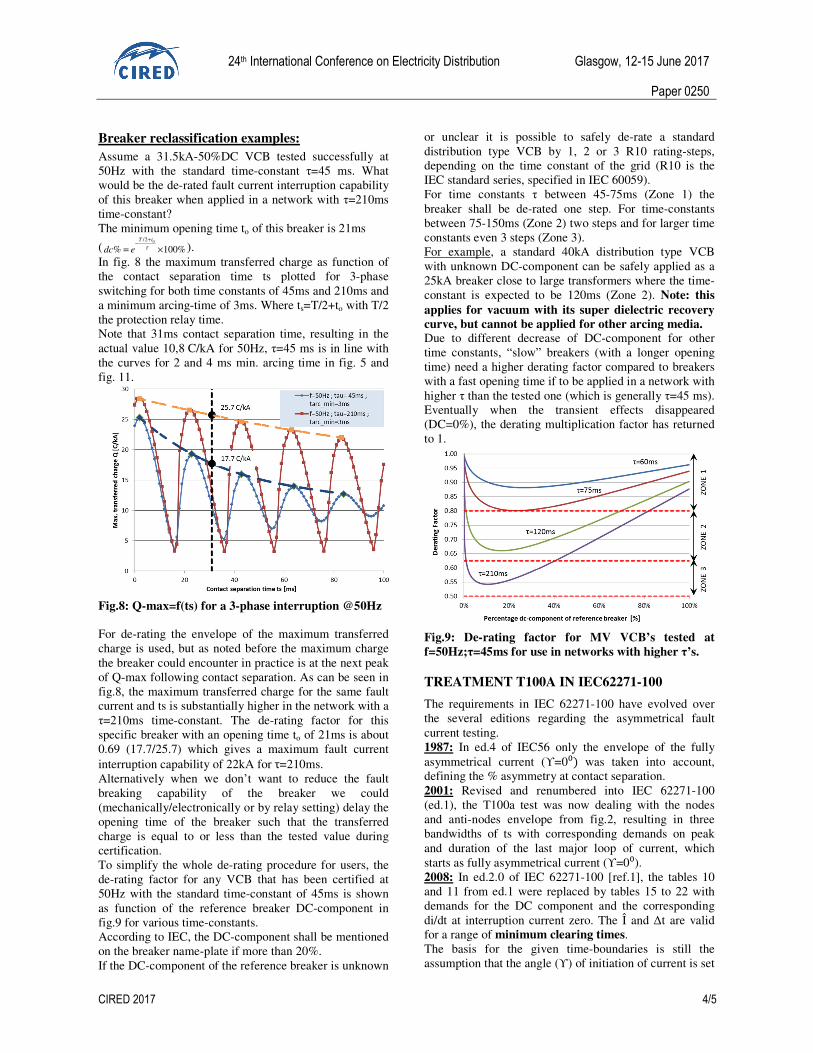
Breaker reclassification examples:
Assume a 31.5kA-50%DC VCB tested successfully at 50Hz with the standard time-constant τ=45 ms. What would be the de-rated fault current interruption capability of this breaker when applied in a network with τ=210ms time-constant? The minimum opening time to of this breaker is 21ms
(0/2
% 100%T t
dc e τ
+−
= × ). In fig. 8 the maximum transferred charge as function of the contact separation time ts plotted for 3-phase switching for both time constants of 45ms and 210ms and a minimum arcing-time of 3ms. Where ts=T/2+to with T/2 the protection relay time. Note that 31ms contact separation time, resulting in the actual value 10,8 C/kA for 50Hz, τ=45 ms is in line with the curves for 2 and 4 ms min. arcing time in fig. 5 and fig. 11.
Fig.8: Q-max=f(ts) for a 3-phase interruption @50Hz For de-rating the envelope of the maximum transferred charge is used, but as noted before the maximum charge the breaker could encounter in practice is at the next peak of Q-max following contact separation. As can be seen in fig.8, the maximum transferred charge for the same fault current and ts is substantially higher in the network with a τ=210ms time-constant. The de-rating factor for this specific breaker with an opening time to of 21ms is about 0.69 (17.7/25.7) which gives a maximum fault current interruption capability of 22kA for τ=210ms. Alternatively when we don’t want to reduce the fault breaking capability of the breaker we could (mechanically/electronically or by relay setting) delay the opening time of the breaker such that the transferred charge is equal to or less than the tested value during certification. To simplify the whole de-rating procedure for users, the de-rating factor for any VCB that has been certified at 50Hz with the standard time-constant of 45ms is shown as function of the reference breaker DC-component in fig.9 for various time-constants. According to IEC, the DC-component shall be mentioned on the breaker name-plate if more than 20%. If the DC-component of the reference breaker is unknown
or unclear it is possible to safely de-rate a standard distribution type VCB by 1, 2 or 3 R10 rating-steps, depending on the time constant of the grid (R10 is the IEC standard series, specified in IEC 60059). For time constants τ between 45-75ms (Zone 1) the breaker shall be de-rated one step. For time-constants between 75-150ms (Zone 2) two steps and for larger time constants even 3 steps (Zone 3). For example, a standard 40kA distribution type VCB with unknown DC-component can be safely applied as a 25kA breaker close to large transformers where the time-constant is expected to be 120ms (Zone 2). Note: this
applies for vacuum with its super dielectric recovery
curve, but cannot be applied for other arcing media. Due to different decrease of DC-component for other time constants, “slow” breakers (with a longer opening time) need a higher derating factor compared to breakers with a fast opening time if to be applied in a network with higher τ than the tested one (which is generally τ=45 ms). Eventually when the transient effects disappeared (DC=0%), the derating multiplication factor has returned to 1.
Fig.9: De-rating factor for MV VCB’s tested at
f=50Hz;τ=45ms for use in networks with higher τ’s.
TREATMENT T100A IN IEC62271-100
The requirements in IEC 62271-100 have evolved over the several editions regarding the asymmetrical fault current testing. 1987: In ed.4 of IEC56 only the envelope of the fully asymmetrical current (ϒ=0⁰) was taken into account, defining the % asymmetry at contact separation. 2001: Revised and renumbered into IEC 62271-100 (ed.1), the T100a test was now dealing with the nodes and anti-nodes envelope from fig.2, resulting in three bandwidths of ts with corresponding demands on peak and duration of the last major loop of current, which starts as fully asymmetrical current (ϒ=0⁰). 2008: In ed.2.0 of IEC 62271-100 [ref.1], the tables 10 and 11 from ed.1 were replaced by tables 15 to 22 with demands for the DC component and the corresponding di/dt at interruption current zero. The Î and ∆t are valid for a range of minimum clearing times. The basis for the given time-boundaries is still the assumption that the angle (ϒ) of initiation of current is set

24th International Conference on Electricity Distribution Glasgow, 12-15 June 2017
Paper 0250
CIRED 2017 5/5
on 0⁰, for the highest asymmetry in a phase; This is not necessarily the worst case ϒ for maximum transferred charge, refer to the discussion of fig.5. For example, assume a minimum opening time of 32 ms, a minimum arcing time of 2 ms and 10 ms reaction time for the relay: this implies ts=42 ms and possible interruption at current zeroes after 44ms. According to fig.5 the Q-max is 14.5 C/kArms (at ϒ=52⁰). Assuming ϒ=0⁰, the demand for max asymmetry, would result in a max transferred charge of ‘only’ 10.3 C/kArms. 2016: In the Amd 2 to come to ed.2 of IEC 62271-100 [ref. 3], the T100a issue is further elaborated in respect to the 3-phase behaviour around the current interruptions. This resulted in a shift from looking at the DC component and di/dt at current interruption of the pole with maximum asymmetrical current, to the latest current zero crossing in the other poles, because that defines the interruption moment in the first pole to clear (fptc) and consequent shift to a 2-phase current. Therefore also the neutral treatment of the network plays its role now, regarding the extended major loop of the last pole to clear (lptc, in case kpp =1.5) versus the second pole to clear (kpp=1,2 or 1,3). Now the arcing times themselves are requested, next to the duration of the major loop and the extended major loop; see fig.4 for major extended loop in the lptc and fig.10 for major loop in the fptc. In table 2 below the part of table 39 of [2] is repeated for the major loop, 50Hz, τ=45 ms, kpp=1.5.
Min. clearing
time (ms) Î
(p.u.) ∆t1
(ms) ∆ta1 (ms)
∆t2 (ms)
∆ta2 (ms)
10.0 < t ≤ 27.0 1.52 13.6 4.1 15.0 10.6 27.0 < t ≤ 47.5 1.33 12.2 3.8 13.7 9.8 47.5 < t ≤ 68.0 1.21 11.4 3.7 12.9 9.2
Table 2: last current loop parameters 3-phase
(f=50Hz, τ=45ms, kpp=1.5)
Fig.10: required times from [2], fig 59b: kpp=1.5,
f=50Hz, τ= 45ms • ∆t1 is the duration of the major loop of fptc (see
fig.10) • ∆ta1 is the time interval between the moment of
current interruption in the fptc after a major loop with the required asymmetry and the moment of the first preceding current zero (see fig.10)
• ∆t2 is the duration of the extended major loop of the lptc for kpp = 1,5 (see fig.4)
• ∆ta2 is the time interval between the moment of current interruption in the lptc after an extended major loop with the required asymmetry for kpp = 1,5 and the moment of the second preceding current zero.
• For the fptc situation (fig.10) the transferred charges with opened contacts are QL1= 6,7 C/kA (during ∆ta1) and the max. occurs for L3: QL3 =11,4 C/kA
• For the lptc situation (fig.4) the transferred charges with opened contacts the max. occurs for L1, being the phase with max asymmetry: QL1 =15,2 C/kA
Checking the whole region for minimum clearing time between 27,0 and 47,5 ms based on 2 ms min. arcing time gives for the contact separation time (=opening- plus relay time) 25,0 to 45,5 ms, see fig. 11 which is a zoom out of fig.5:
Fig.11:Q-max during a 3-phase current interruption
(f=50Hz, τ=45ms, t_arc-min=2ms) Based on 2 ms the IEC related Q-max will be less than maximal possible in the region ts = 25 to 28 ms (so min. clearing time 27-30 ms): 15,2 C/kA where according to fig.5a up to 18,4 C/kA is possible.
CONCLUSIONS:
• Eaton uses the critical transferred charge criterion to predict if a VCB is fit for application in networks with different time constants τ, short-circuit ratings and also regarding impact of nearby generator contributions with the possible associated delayed current zeroes;
• The cumulative transferred charge is used in relation to contact wear, so electrical life limits. At least 30 times the Isc can randomly be interrupted with Eaton VCB’s;
• The latest IEC 62271-100 approach [ref.3] is still not worst case for all min. clearing times in respect to transferred charge, but will be sufficient for application in practice.
REFERENCES [1] IEC 62271-100 (ed 2.0) 2008, “High-voltage
switchgear and controlgear –Part 100: Alternating-
current circuit-breakers”, IEC, Geneva, CH [2] M.B.J. Leusenkamp, “Vacuum Interrupter Model
Based on Breaking Tests”, IEEE Trans. Plasma Sci., Vol. 27, No. 4, pp. 969-976, Aug.1999
[3] IEC 17A/1118/CDV 2016, ‘Draft Amendment 2 to
IEC 62271-100 Ed. 2”, IEC, Geneva, CH