transistor hf linear power amplifier 500w 5” lcd control
TRANSCRIPT

eb104.ru™
User’s Guide
TransistorHF Linear Power Amplifier 500W
5” LCD controlModel EB500+

Contents
Introduction ……………………………………………………….…………………………… ……..3
Operating Precautions for the EB500…………………………………………………..……………… ……..3
Features of the EB500 Amplifier ……………………………………………………………………… ……..3
Specifications of the EB500 Amplifier ……………………………….……………………………….. ……..5
Front Panel Description …………………………………………………………………………. ……..6
Rear Panel Description ………………………………………………………………………….. ……..6
Control Cable Connector ……………………………………………………………………… ……..7
SunSDR2 Settings for the Amplifier ……………...…………………………………………... ……..7
EB300 Power Amplifier Protection Circuits ……………..……………………………………………. …......8
Schematics ……………………………………………...………………………………………. ……10
2

Introduction
Before using the EB500+ HF linear power amplifier carefully read this manual and the otherdocumentations that came with your amplifier. This allows you to reduce the risks of the product’sfailure.
EB500 - is a transistor HF linear power amplifier designed for use with amateur radio stations.The features of the EB500+ amplifier are:
ready for instant operation; compact size, light weight; no need for component replacements due to wear and tear; increased service life; absence of high voltage in the high frequency parts; automatic control of the operation process
Operating Precautions for the EB500+
For the proper operation of the power amplifier, it is necessary to observe the followingprecautions:
Do not operate the amplifier without a proper electrical grounding system;
Connect the radio transceiver to a ground system so as to provide the most efficient and stableoperation of all the equipments of the amateur radio station. This will reduce potential noiseand RF interference;
It is necessary to switch off the amplifier in order to eliminate the causes of the emergency stopafter repeated triggering of the amplifier’s protection systems. The repeated activation of theprotection devices may damage the expensive MOSFET transistors;
Do not adjust or tune a matching device installed between the output of the amplifier and theantenna with power that exceeds 30 W, i.e.: 10% of the maximum output power of theamplifier;
To work in RTTY / FM/Digital mode, you need to lower the output power of the amplifier to50% of the output power level required for CW / SSB mode;
Do not drop the amplifier. The mechanical shock due to the impact on the product’s casing aswell as the possible entry of foreign objects - can lead to the failure of the electroniccomponents of the EB300 power amplifier.
EB500+ Amplifier Features
The built-in potentiometers in the power protection and BIAS voltage control circuits wereadjusted in the correct position during the setup and testing of the equipment. Any spontaneous change inthe position of the potentiometers will result in having to re-configure the amplifier using precisioninstruments.
Before using the power amplifier, you must connect a dummy load of 50 Ohms at 500 Watts ora properly matched antenna system to the antenna output connector. The improper load of the amplifier,however, may not have a negative effect on the output RF transistors (due to the high SWR protectioncircuit).
For the output power of 500 W, the input power level should be 20 watts. Do not usetransmitting devices with a capacity of more than 20 watts with the amplifier.
3

The operation is designed for 50 ohms impedance. Use antenna-feeder devices with the valueof 50 ohms and an SWR that does not exceed the value of 2.0: 1 on all frequencies as much as possible.The operation of the amplifier is possible without any additional matching devices. However, if the SWRis greater than 2.0: 1, it is recommended to use additional matching devices.
Two high-quality SD2933 MOSFET transistors manufactured by Microsemi are installed in theoutput stage of the power amplifier (see Table 1).
The power rating of a SD2933 transistor (!) - is 300 W at a frequency of 30 MHz. TheBroadband Power Amplifier features makes it completely ready to use after selecting the operating range,without any further need of matching at the final stage. The peculiarity of these transistors is the relativelyhigh bias voltage for class AB, which allows disabling it to almost zero power output. This makes itpossible to ensure the maximum performance protection of the transistor from breakdown due to a highVSWR value of the antenna and in other critical situations.
The use of High Linearity SD2933 transistors also yielded an IMD3 of -36 dbC.The power amplifier is equipped with special high-speed protection circuits. For example, on
the excess of output power, high SWR at the antenna, limiting the level of excitation (input) voltage,overheating, etc.
To control the working parameters of the power amplifier there is a digital meter that displaysthe amplifier’s output power level the SWR value.
EB300 Specifications
Frequency range 1,8 - 54 MHz (including WARC)Types of radiation SSB, CW, RTTYInput Power 20 WOutput power 500 WSWR max. 2.0: 1Supply voltage 48-53V, +13,8V (1A)Current consumption 10-12 AInput impedance 50 ohms (unbalanced)Output impedance 50 ohms (unbalanced)Input / Output connectors UHF SO-239Amplifier circuit push-pull, class ABOutput/Final stage transistors 2xMOSFET
Equipment:
HF power amplifier EB500+ 1 pc.Power cable 1 pc.SunSDR2 control cable (optional) optionalUser’s Manual 1 pc.
4

Front Panel Description
1. 1. Key switch on and off the power amplifier.2. 2. Indication and control:
3. Power output W - power output indication4. SWR - SWR level5. Current A - current in amperes6. Temperature - amplifier temperature in degrees Celsius7. Voltage V - Volt supply voltage8. Error HIGH SWR - lights up red when the protection is turned on when the permissible SWR is
exceeded9. Error HIGH PWR - lights up red when the protection is turned on when the permissible output power
is exceeded10. Error HIGH CURRENT - lights up red when the protection is turned on after exceeding the
permissible current11. ON AIR - green in transmit mode12. 160 - 1.8 MHz13. 80 - 3.5 MHz14. 40 - 7 MHz15. 30-20 - 10/14 MHz16. 17-15 - 18/21 MHz17. 12-10 - 24/28 MHz18. 6 - 54 MHz19. AUTO - automatic range switching mode when using an external device (automatic decoder)20. Turn the amplifier off and on again to reset the protection circuit.
5
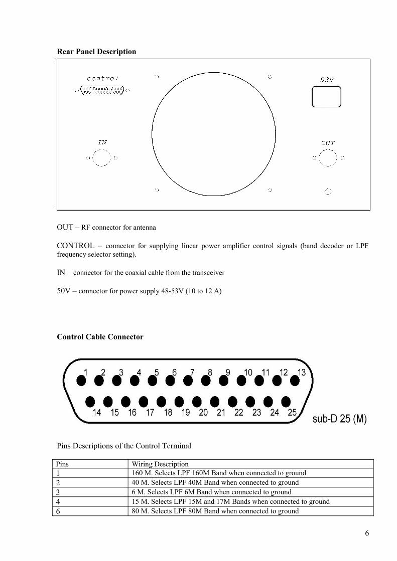
Rear Panel Description
OUT – RF connector for antenna
CONTROL – connector for supplying linear power amplifier control signals (band decoder or LPFfrequency selector setting).
IN – connector for the coaxial cable from the transceiver
50V – connector for power supply 48-53V (10 to 12 A)
Control Cable Connector
Pins Descriptions of the Control Terminal
Pins Wiring Description1 160 M. Selects LPF 160M Band when connected to ground2 40 M. Selects LPF 40M Band when connected to ground 3 6 M. Selects LPF 6M Band when connected to ground4 15 M. Selects LPF 15M and 17M Bands when connected to ground6 80 M. Selects LPF 80M Band when connected to ground
6

8 20 M. Selects LPF 20M and 30M Bands when connected to ground9 10 M. Selects LPF 10M and 12M Bands when connected to ground15 PTT switch. Transmit Mode when connected to ground12,13 +13.8V22,23,24,25 Ground
EB300+ Power Amplifier Protection Circuits
1. Overheating Protection
In case of excessive temperature of more than + 50 ° C, the inner surface of the cooling radiatorwill trigger a bimetallic thermal switch, located on the radiator (heat sink) to engage the forced coolingmode. In case of excessive temperature of more than + 65 ° C, the inner surface of the cooling radiatorwill trigger another bimetallic thermal switch and PTT line will be disconnected.The power amplifiercannot be turned on again until the radiator cools back to the normal temperature. Wait until the heat sinkhas cooled down and switch on the amplifier.
2. Excessive Allowable Maximum Output Power Protection
If the RF output voltage level exceeds a set threshold, the protection circuitry mounted at theEB300 output will be tripped. The protection warning LED marked P lights up .
3. High SWR Protection
If the SWR of the load exceeds the value of 2.0: 1, it will trigger the protection system. Theprotection warning LED marked SWR lights up.
In the case of tripping, be sure to check the antenna VSWR. If you cannot match the antenna, itis efficient to use an antenna tuner.
4. Excessive Allowable Maximum Drain current Protection
If the Drain current level exceeds a set threshold, the protection circuitry mounted at the EB500output will be tripped. The protection warning LED marked I lights up .
Attention! To reset the amplifier to normal operation, turn off the power button «power» andturn it on again after 3-5 seconds. Restarting the system does not apply to the safety shutdown of theamplifier caused by excessive temperature. The hysteresis thermal switch will enable the amplifier to beswitch on when the radiator (heat sink) will cool down to + 45C.
7

8