transmission resource management pd
TRANSCRIPT
RAN
Transmission Resource Management Parameter Description
Issue 01
Date 2009-03-30
Huawei Technologies Co., Ltd. provides customers with comprehensive technical support and service. For any assistance, please contact our local office or company headquarters.
Huawei Proprietary and Confidential Copyright © Huawei Technologies Co.,
Ltd
Huawei Technologies Co., Ltd.
Address: Huawei Industrial Base
Bantian, Longgang
Shenzhen 518129
People's Republic of China
Website: http://www.huawei.com
Email: [email protected]
Copyright © Huawei Technologies Co., Ltd. 2009. All rights reserved.
No part of this document may be reproduced or transmitted in any form or by any means without prior written consent of Huawei Technologies Co., Ltd.
Trademarks and Permissions
and other Huawei trademarks are trademarks of Huawei Technologies Co., Ltd.
All other trademarks and trade names mentioned in this document are the property of their respective holders.
Notice
The information in this document is subject to change without notice. Every effort has been made in the preparation of this document to ensure accuracy of the contents, but all statements, information, and recommendations in this document do not constitute the warranty of any kind, express or implied.
Huawei Proprietary and Confidential Copyright © Huawei Technologies Co.,
Ltd
RANTransmission Resource Management Parameter Description
About This Document
About This Document
Author
Prepared by Xing Ruizhi Date 2008-10-16
Edited by Sun Jingshu Date 2008-11-20
Reviewed by Date
Translated by Zhang Lijun Date 2008-12-10
Tested by Lu Feng Date 2009-01-10
Approved by Duan Zhongyi Date 2009-03-30
Issue 01 (2009-03-30) Huawei Proprietary and Confidential Copyright © Huawei Technologies Co.,
Ltd
iii

RANTransmission Resource Management Parameter Description
Contents
Contents
1 Change History...........................................................................1-2
2 Introduction...............................................................................2-2
3 TRM Algorithm Overview.............................................................3-23.1 Contents of TRM Algorithms.........................................................................................................................3-2
3.2 Requirements of TRM Algorithms.................................................................................................................3-2
3.2.1 Networking Requirement......................................................................................................................3-2
3.2.2 QoS Requirement..................................................................................................................................3-2
3.2.3 Capacity Requirement...........................................................................................................................3-2
3.2.4 Differentiated Service Requirement......................................................................................................3-2
4 Transmission Resources..............................................................4-24.1 Transmission Resource Introduction..............................................................................................................4-2
4.2 Physical Transmission Resources...................................................................................................................4-2
4.2.1 Physical Layer Resources of the RNC for ATM Transport...................................................................4-2
4.2.2 Physical and Data Link Layer Resources of the RNC for IP Transport................................................4-2
4.3 LP Resources..................................................................................................................................................4-2
4.3.1 LP Introduction......................................................................................................................................4-2
4.3.2 ATM LP at the RNC..............................................................................................................................4-2
4.3.3 IP LP at the RNC...................................................................................................................................4-2
4.3.4 Resource Group at the RNC..................................................................................................................4-2
4.3.5 ATM LP at the NodeB...........................................................................................................................4-2
4.3.6 IP LP at the NodeB................................................................................................................................4-2
4.4 Path Resources................................................................................................................................................4-2
4.4.1 AAL2 Path.............................................................................................................................................4-2
4.4.2 IP Path...................................................................................................................................................4-2
4.5 Priorities.........................................................................................................................................................4-2
5 TRM Mapping..............................................................................5-25.1 Traffic Bearer..................................................................................................................................................5-2
5.2 Transport Bearer.............................................................................................................................................5-2
5.2.1 Type of Path...........................................................................................................................................5-2
5.2.2 DiffServ and DSCP...............................................................................................................................5-2
5.3 Mapping from Traffic Bearers to Transport Bearers......................................................................................5-2
Issue 01 (2009-03-30) Huawei Proprietary and Confidential Copyright © Huawei Technologies Co.,
Ltd
v
RANTransmission Resource Management Parameter Description
Contents
5.3.1 RNC-Oriented Default Mapping...........................................................................................................5-2
5.3.2 Adjacent-Node-Oriented Mapping........................................................................................................5-2
6 Load Control...............................................................................6-26.1 Definition of Load..........................................................................................................................................6-2
6.2 Bandwidth Reserved for Services..................................................................................................................6-2
6.3 Admission Control..........................................................................................................................................6-2
6.3.1 Admission Control Algorithm...............................................................................................................6-2
6.3.2 Load Balancing.....................................................................................................................................6-2
6.3.3 Admission Procedure.............................................................................................................................6-2
6.4 Intelligent Access Control..............................................................................................................................6-2
6.5 Load Reshuffling and Overload Control........................................................................................................6-2
6.5.1 Iub Congestion Detection......................................................................................................................6-2
6.5.2 Iub Overload Detection.........................................................................................................................6-2
6.5.3 Congestion and Overload Handling......................................................................................................6-2
7 User Plane Processing.................................................................7-27.1 Overview of User Plane Processing...............................................................................................................7-2
7.2 Hub Scheduling and Shaping.........................................................................................................................7-2
7.2.1 RNC Scheduling and Shaping...............................................................................................................7-2
7.2.2 NodeB Scheduling and Shaping............................................................................................................7-2
7.3 Congestion Control of Iub User Plane............................................................................................................7-2
7.4 Downlink Iub Congestion Control Algorithm................................................................................................7-2
7.4.1 Overview of the Downlink Iub Congestion Control Algorithm............................................................7-2
7.4.2 RNC RLC Retransmission Rate-Based Downlink Congestion Control Algorithm..............................7-2
7.4.3 RNC Backpressure-Based Downlink Congestion Control Algorithm..................................................7-2
7.4.4 RNC R99 Single Service Downlink Congestion Control Algorithm....................................................7-2
7.4.5 NodeB HSDPA Adaptive Flow Control Algorithm...............................................................................7-2
7.5 Uplink Iub Congestion Control Algorithm.....................................................................................................7-2
7.5.1 Overview of the Uplink Iub Congestion Control Algorithm.................................................................7-2
7.5.2 NodeB Backpressure-Based Uplink Congestion Control Algorithm (R99 and HSUPA).....................7-2
7.5.3 NodeB Uplink Bandwidth Adaptive Adjustment Algorithm.................................................................7-2
7.5.4 RNC R99 Single Service Uplink Congestion Control Algorithm.........................................................7-2
7.5.5 NodeB Cross-Iur Single HSUPA Service Uplink Congestion Control Algorithm................................7-2
7.6 Iub Efficiency Improvement...........................................................................................................................7-2
7.6.1 IP RAN FP-MUX..................................................................................................................................7-2
7.6.2 IP RAN Header Compression...............................................................................................................7-2
7.6.3 FP Silent Mode......................................................................................................................................7-2
7.7 IP PM..............................................................................................................................................................7-2
8 TRM Parameters.........................................................................8-28.1 Description.....................................................................................................................................................8-2
8.2 Values and Ranges..........................................................................................................................................8-2
Issue 01 (2009-03-30) Huawei Proprietary and Confidential Copyright © Huawei Technologies Co.,
Ltd
vi
RANTransmission Resource Management Parameter Description
Contents
9 TRM Reference Documents..........................................................9-2
10 Appendix................................................................................10-210.1 Default TRMMAP Table for the ATM-Based Iub and Iur Interfaces.........................................................10-2
10.2 Default TRMMAP Table for the IP-Based Iub and Iur Interfaces..............................................................10-2
10.3 Default TRMMAP Table for the ATM&IP-Based Iub Interface................................................................10-2
10.4 Default TRMMAP Table for the Hybrid-IP-Based Iub Interface...............................................................10-2
10.5 Default TRMMAP Table for the ATM-Based Iu-CS Interface...................................................................10-2
10.6 Default TRMMAP Table for the IP-Based Iu-CS Interface.......................................................................10-2
10.7 Default TRMMAP Table for the Iu-PS Interface.......................................................................................10-2
Issue 01 (2009-03-30) Huawei Proprietary and Confidential Copyright © Huawei Technologies Co.,
Ltd
vii
RANTransmission Resource Management Parameter Description
Error! Use the Home tab to apply 标题 1 to the text that you want to appear here.Error! Use the
Home tab to apply 标题 1 to the text that you want to appear here.
1 Change History
The change history provides information on the changes in different document versions.
Document and Product Versions
Table 1-1 Document and product versions
Document Version RAN Version
01 (2009-03-30) 11.0
Draft (2009-03-10) 11.0
Draft (2009-01-15) 11.0
This document is based on the BSC6810 and 3900 series NodeBs.
The available time of each feature is subject to the RAN product roadmap.
There are two types of changes, which are defined as follows:
Feature change: refers to the change in the transmission resource management.
Editorial change: refers to the change in the information that was inappropriately described or the addition of the information that was not described in the earlier version.
01 (2009-03-30)
This is the document for the first commercial release of RAN11.0.
Compared with draft (2009-03-10) of RAN11.0, this issue incorporates the following changes:
Change Type
Change Description Parameter Change
Feature change None. None.
Issue 01 (2009-03-30) Huawei Proprietary and Confidential Copyright © Huawei Technologies Co.,
Ltd
1
RANTransmission Resource Management Parameter Description
Error! Use the Home tab to apply 标题 1 to the text that you want to appear here.Error! Use the
Home tab to apply 标题 1 to the text that you want to appear here.
Change Type
Change Description Parameter Change
Editorial change
The description of UBR PLUS is changed to UBR +.
None.
Draft (2009-03-10)
This is the second draft of the document for RAN11.0.
Compared with draft (2009-01-15), draft (2009-03-10) optimizes the description.
Draft (2009-01-15)
This is the initial draft of the document for RAN11.0.
Compared with 02 (2008-07-30) of RAN10.0, draft (2009-01-15) incorporates the following changes:
Change Type
Change Description Parameter Change
Feature change None. None.
Editorial change
General documentation change:
The contents of the Iub Overbooking Description are added to this document, and the description in this document is revised.
None.
The title of the document is changed from Transmission Resource Management Description to Transmission Resource Management Parameter Description.
None.
Parameter names are replaced with parameter IDs.
None.
None. The added parameters are as follows: MoniterPrd TimeToTriggerA EventAThred PendingTimeA TimeToTriggerB TimeToMoniter EventBThred PendingTimeB
Issue 01 (2009-03-30) Huawei Proprietary and Confidential Copyright © Huawei Technologies Co.,
Ltd
2
RANTransmission Resource Management Parameter Description
Error! Use the Home tab to apply 标题 1 to the text that you want to appear here.Error! Use the Home tab to apply 标题 1 to the text that
you want to appear here.
2 Introduction
Transmission Resource Management (TRM) is aimed at increasing the system capacity in various networking scenarios without affecting the Quality of Service (QoS). In addition, TRM provides differentiated services for Best Effort (BE) services to improve the data transmission efficiency.
TRM involves management of the transmission resources on the Iub, Iur, and Iu interfaces.
Transmission resources are one type of resource that the UTRAN provides. Closely related to TRM algorithms are Radio Resource Management (RRM) algorithms, such as the scheduling algorithm and load control algorithm for the Uu interface. The TRM algorithm policies should be consistent with the RRM algorithm policies.
Compared with the transmission on the other interfaces, the transmission on the Iub interface is of higher costs and more complex networking modes and has a greater impact on the system performance. Therefore, this document describes only the TRM algorithms for the Iub interface.
Intended Audience
This document is intended for:
System operators who need a general understanding of transmission resource management.
Personnel working on Huawei products or systems.
Impact Impact on system performance
None.
Impact on other features
None.
Network Elements Involved
Table 2-1 lists the Network Elements (NEs) involved in TRM.
Issue 01 (2009-03-30) Huawei Proprietary and Confidential Copyright © Huawei Technologies Co.,
Ltd
1
RANTransmission Resource Management Parameter Description
Error! Use the Home tab to apply 标题 1 to the text that you want to appear here.Error! Use the Home tab to apply 标题 1 to the text that
you want to appear here.
Table 2-1 NEs involved in TRM
UE NodeB RNC MSC Server
MGW SGSN GGSN HLR
– √ √ – √ √ – –
NOTE: –: not involved √: involved
UE = User Equipment, RNC = Radio Network Controller, MSC Server = Mobile Service Switching Center Server, MGW = Media Gateway, SGSN = Serving GPRS Support Node, GGSN = Gateway GPRS Support Node, HLR = Home Location Register
Issue 01 (2009-03-30) Huawei Proprietary and Confidential Copyright © Huawei Technologies Co.,
Ltd
2
3 TRM Algorithm Overview
3.1 Contents of TRM AlgorithmsTRM algorithms cover the following aspects:
Transmission resources: basic transmission resources, including key objects such as ports and paths, and attributes such as priorities and bandwidth.
Mapping from traffic bearers to transmission bearers: Transport networks can provide priority-based services. According to the QoS requirements, traffic class, Allocation/Retention Priority (ARP), Traffic Handling Priority (THP), and radio bearer types of services, the transport networks map traffic to the transport bearers with the appropriate characteristics of transport types and transmission priorities.
Load control for transmission resources: The TRM algorithms control access of users to the network. With the QoS guaranteed, the network allows access of users to the maximum extent.
Congestion control on the user plane of the transport network layer: For non-real-time (NRT) services, the control helps prevent congestion and packet loss.
Improvement in efficiency on the user plane of the transport network layer: The bandwidth occupied by services is reduced to improve the transmission efficiency on the user plane.
3.2 Requirements of TRM Algorithms
3.2.1 Networking RequirementThe typical networking scenarios for the Iub interface are as follows:
Direct connection: The RNC is directly connected to a NodeB through a physical port, the bandwidth of which is exclusively occupied by this Iub interface. This is the simplest scenario, in which the TRM algorithms are also simple.
Transmission convergence: As shown in Figure 3-1, the Iub traffic of more than one NodeB is converged, for example, on the transport network or by the hub NodeB. In this scenario, the transmission convergence information, which can serve as the input to TRM algorithms, must be configurable. The TRM algorithms applicable in transmission convergence scenarios are relatively complicated.
Issue 01 (2009-03-30) Huawei Proprietary and Confidential Copyright © Huawei Technologies Co.,
Ltd
1
Figure 3-1 Iub transmission convergence networking
NB = NodeB BW = bandwidth BW0 = bandwidth of the physical port
Bandwidth being variable: The bandwidth on the transport network might be variable. For example, the bandwidth of Asymmetric Digital Subscriber Line (ADSL) transmission is variable. In this case, the TRM algorithms need to be able to detect the available bandwidth.
ATM&IP dual stack: ATM and IP transmission resources are available for one Iub interface at the same time so that the transmission cost is reduced.
Hybrid IP: High-QoS transmission (such as IP over E1) and low-QoS transmission (IP over FE) are applicable to one Iub interface at the same time so as to enable differentiated management of services.
RAN sharing: Operators share the physical bandwidth. In this case, some bandwidth should be reserved for each operator.
Table 3-1 lists the types of transport applicable to each interface.
Table 3-1 Types of transport applicable to each interface
Interface ATM IP ATM&IP Dual Stack Hybrid IP
Iub √ √ √ √
Iur √ √ – –
Iu-CS √ √ – –
Iu-PS – √ – –
3.2.2 QoS RequirementThe WCDMA system supports the following types of service:
Signaling, such as SRB, SIP, NCP, and CCP
Issue 01 (2009-03-30) Huawei Proprietary and Confidential Copyright © Huawei Technologies Co.,
Ltd
2

Real-time (RT) service, such as conversational and streaming
NRT or BE service, such as interactive and background
The requirements are as follows:
For RT services, the bandwidth must be guaranteed. In terms of QoS, RT services do not allow packet loss or buffering of a huge data volume. The buffering of a huge data volume will result in an increase in the delay.
For NRT services, the Guaranteed Bit Rate (GBR) is not provided, so the bandwidth is not required to be guaranteed. In the case of resource shortage, the data can be buffered so as to reduce the traffic throughput. In order to guarantee the basic QoS of NRT services, the RAN allows the configuration of the GBR for NRT services.
For the signaling such as NCP, CCP, SRB, and SIP, the traffic is low and its performance is closely related to Key Performance Indicators (KPIs) of the network. Therefore, the transmission of signaling takes precedence, and packet loss and long delay should be prevented.
For R99 services, the time window mechanism is employed in the downlink, and the Iub delay and jitter are required to stay within a certain range.
3.2.3 Capacity RequirementThe capacity requirements are as follows:
With the QoS guaranteed, the network should allow access of users to the maximum extent. This is mainly implemented by the load control algorithm.
When data needs to be transferred for NRT services with innate bursty characteristic, the bandwidth should be fully utilized to ensure a high throughput and prevent congestion. This is mainly implemented by the user plane congestion control algorithm.
3.2.4 Differentiated Service RequirementDifferent types of service have different requirements. Therefore, the level of quality guaranteed varies according to the type of service. Service differentiation needs to take the following factors into consideration:
Traffic class: The WCDMA system provides four traffic classes: conversational, streaming, interactive, and background, in descending order of traffic priority.
User priority: There are three user priorities: Gold, Silver, and Copper, in descending order of priority. The mapping between user priorities and ARPs is configurable. For details, see the Load Control Parameter Description.
Type of radio bearer: R99, High Speed Downlink Packet Access (HSDPA), and High Speed Uplink Packet Access (HSUPA).
To provide differentiated services is to provide different QoSs according to the traffic class, user priority, and type of radio bearer. The details are as follows:
Differentiated service requirement for the transport layer: The transport layer provides multiple types of transport bearers and transmission priorities. The appropriate type of transport bearer and transmission priority should be selected according to the traffic class, user priority, and radio bearer type of the service. The transmission of high-priority traffic takes precedence upon transmission congestion, and thus the frame loss rate of the traffic is low and the transmission delay is short. For details, see chapter 5 "TRM Mapping."
Issue 01 (2009-03-30) Huawei Proprietary and Confidential Copyright © Huawei Technologies Co.,
Ltd
3
Differentiated service requirement for the load control algorithm: The load control algorithm for the Uu interface already supports differentiated services. The load control algorithm for transmission resources should keep consistent with that for the Uu interface. For details, see chapter 6 "Load Control."
Differentiated service requirement for the GBR of NRT services: For NRT services, the GBR is configurable by running the SET USERGBR command according to the traffic class, user priority, and bearer type (that is, DCH or HSPA) of the services.
Differentiated service requirement for the allocation of bandwidth for NRT services: The activity of NRT services does not follow any obvious rule. When the demand from NRT services for the transmission bandwidth exceeds the total available Iub bandwidth, the bandwidth needs to be allocated to the services in a certain way. For High Speed Packet Access (HSPA) services, when Uu resources face a hurdle, the Uu resources are allocated to NRT services according to the Scheduling Priority Indicator (SPI) weight. Accordingly, in the case of Iub transmission resource shortage, the Iub transmission resources also need to be allocated to the NRT services according to the SPI. For details, see section 7.3 "Congestion Control of Iub User Plane."
Issue 01 (2009-03-30) Huawei Proprietary and Confidential Copyright © Huawei Technologies Co.,
Ltd
4
4 Transmission Resources
4.1 Transmission Resource IntroductionTransmission resources consist of ATM transmission resources and IP transmission resources.
ATM transmission resources are as follows:
Physical transmission resources: E1/T1, channelized STM-1, unchannelized STM-1, ATM physical port (IMA, UNI, and fractional ATM)
Logical Port (LP) resources: ATM hub LP and ATM leaf LP
Path resources: AAL2 path, SAAL link, and IPoA PVC
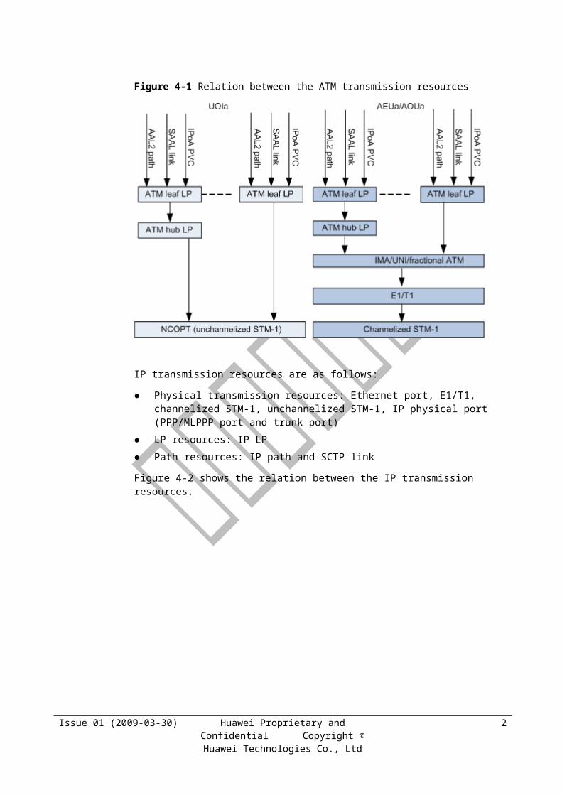
Figure 4-1 shows the relation between the ATM transmission resources.
Figure 4-1 Relation between the ATM transmission resources
IP transmission resources are as follows:
Physical transmission resources: Ethernet port, E1/T1, channelized STM-1, unchannelized STM-1, IP physical port (PPP/MLPPP port and trunk port)
Issue 01 (2009-03-30) Huawei Proprietary and Confidential Copyright © Huawei Technologies Co.,
Ltd
1

LP resources: IP LP
Path resources: IP path and SCTP link
Figure 4-2 shows the relation between the IP transmission resources.
Figure 4-2 Relation between the IP transmission resources
4.2 Physical Transmission Resources
4.2.1 Physical Layer Resources of the RNC for ATM Transport
The following types of physical transmission port are available for ATM transport:
E1/T1: electrical ports on the AEUa board
Channelized STM-1/OC-3: optical ports on the AOUa board
Unchannelized STM-1/OC-3c: optical ports on the UOIa board
Table 4-1 describes the ATM interface boards.
Table 4-1 ATM interface boards
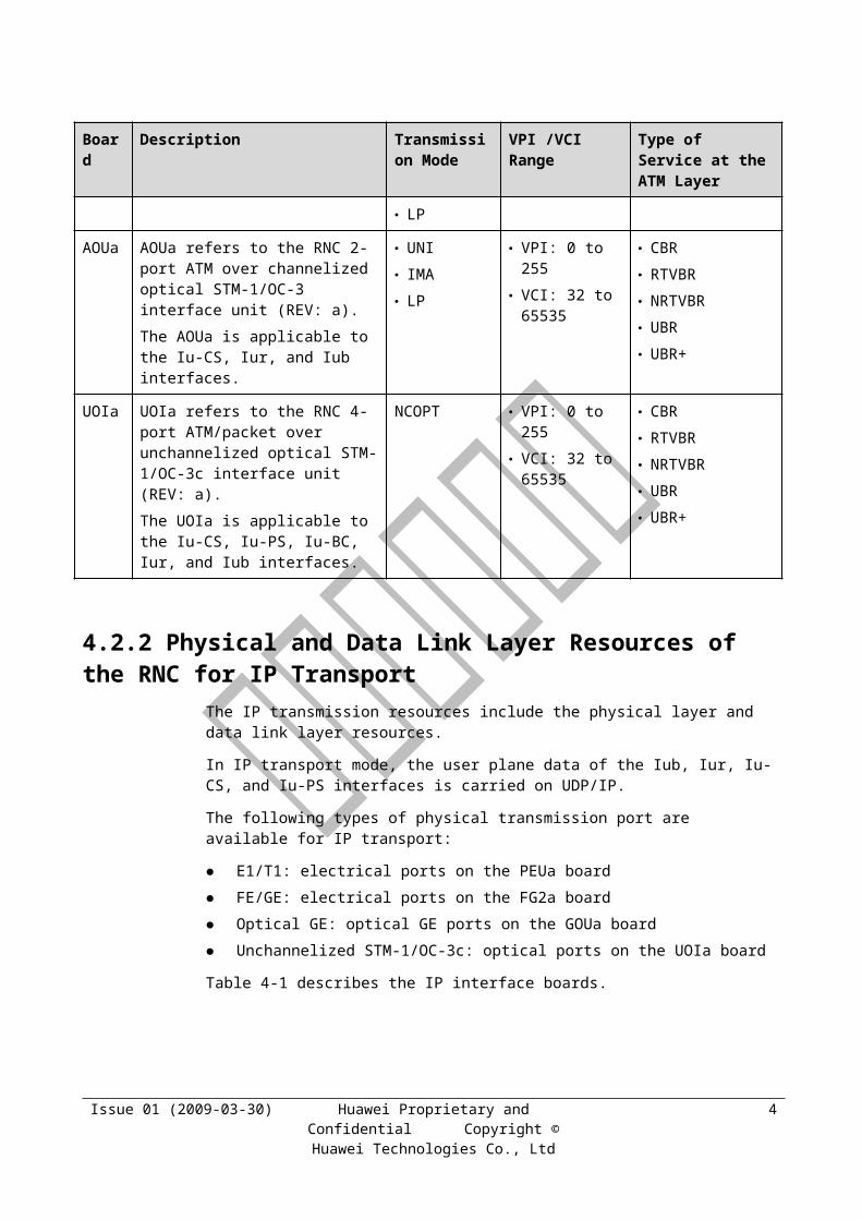
Board
Description Transmission Mode
VPI /VCI Range
Type of Service at the ATM Layer
AEUa AEUa refers to the RNC 32-port ATM over E1/T1 interface unit (REV: a).
The AEUa is applicable to the Iu-CS, Iur, and Iub interfaces.
UNI IMA Fractional
ATM Fractional
IMA
VPI: 0 to 255 VCI: 32 to
65535
CBR RTVBR NRTVBR UBR UBR+
Issue 01 (2009-03-30) Huawei Proprietary and Confidential Copyright © Huawei Technologies Co.,
Ltd
2
Board
Description Transmission Mode
VPI /VCI Range
Type of Service at the ATM Layer
LP
AOUa AOUa refers to the RNC 2-port ATM over channelized optical STM-1/OC-3 interface unit (REV: a).
The AOUa is applicable to the Iu-CS, Iur, and Iub interfaces.
UNI IMA LP
VPI: 0 to 255 VCI: 32 to
65535
CBR RTVBR NRTVBR UBR UBR+
UOIa UOIa refers to the RNC 4-port ATM/packet over unchannelized optical STM-1/OC-3c interface unit (REV: a).
The UOIa is applicable to the Iu-CS, Iu-PS, Iu-BC, Iur, and Iub interfaces.
NCOPT VPI: 0 to 255 VCI: 32 to
65535
CBR RTVBR NRTVBR UBR UBR+
4.2.2 Physical and Data Link Layer Resources of the RNC for IP Transport
The IP transmission resources include the physical layer and data link layer resources.
In IP transport mode, the user plane data of the Iub, Iur, Iu-CS, and Iu-PS interfaces is carried on UDP/IP.
The following types of physical transmission port are available for IP transport:
E1/T1: electrical ports on the PEUa board
FE/GE: electrical ports on the FG2a board
Optical GE: optical GE ports on the GOUa board
Unchannelized STM-1/OC-3c: optical ports on the UOIa board
Table 4-1 describes the IP interface boards.
Table 4-1 IP interface boards
Board Description Transmission Mode
PEUa PEUa refers to the RNC 32-port packet over E1/T1 interface unit (REV: a).
The PEUa is applicable to the IP-based Iub, Iur, and Iu-CS interfaces.
PPP MLPPP MCPPP
FG2a FG2a refers to the RNC packet over electrical 8-port FE or 2-port GE Ethernet interface unit (REV: a).
The FG2a is applicable to the IP-based Iub, Iur, Iu-CS, and Iu-PS interfaces.
IP over Ethernet
GOUa GOUa refers to the RNC 2-port packet over optical GE IP over Ethernet
Issue 01 (2009-03-30) Huawei Proprietary and Confidential Copyright © Huawei Technologies Co.,
Ltd
3
Board Description Transmission Mode
Ethernet interface unit (REV: a).
The GOUa is applicable to the IP-based Iub, Iur, Iu-CS, and Iu-PS interfaces.
UOIa The board provides four unchannelized STM-1/OC-3c optical ports and supports IP over SDH/SONET.
PPP
POUa POUa refers to the RNC 2-port packet over channelized optical STM-1/OC-3 interface unit (REV: a).
The POUa provides two IP over channelized STM-1/OC-3 optical ports and supports IP over E1/T1 over SDH/SONET.
The POUa supports 42 MLPPP groups in E1 mode and 64 MLPPP groups in T1 mode.
PPP MLPPP
4.3 LP Resources
4.3.1 LP IntroductionAfter the physical transmission resources and path resources are configured, the system can start to operate and services can be established. There are problems, however, in the following scenarios:
Transmission convergence
Transmission convergence can be performed either on the transport network (for example, convergence of NB1 and NB2, as shown in Figure 4-1) or at the hub NodeB (for example, convergence of NB3 and NB4 at NB1, as shown in Figure 4-1). If only physical transmission resources and path resources are configured, the bandwidth constraints at the convergence points are unavailable. As shown in Figure 4-1, the total available bandwidth BW0 is known, but the values of BW1 through BW4 are unknown. Thus, the admission algorithm does not work properly. For example, if the total reserved bandwidth at NB2 exceeds BW2, congestion and packet loss may occur and in the downlink, the total volume of data sent to NB2 may exceed BW2.
Issue 01 (2009-03-30) Huawei Proprietary and Confidential Copyright © Huawei Technologies Co.,
Ltd
4
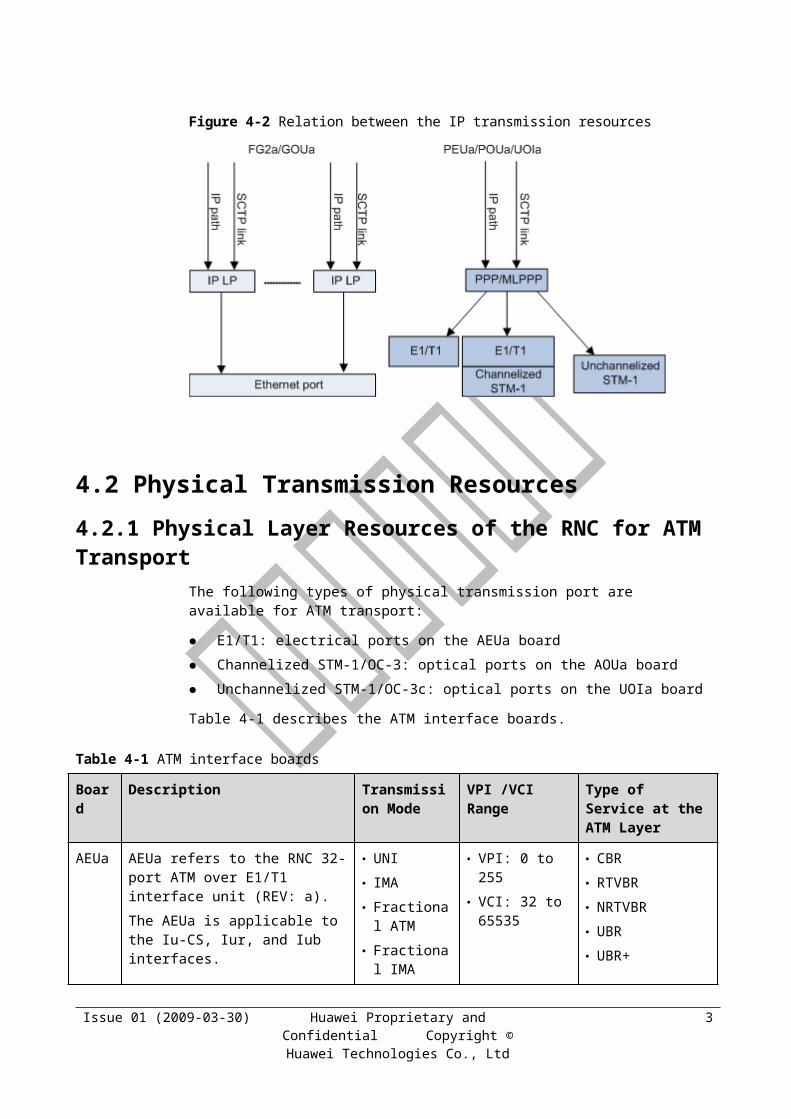
Figure 4-1 Iub transmission convergence
RAN sharing
Operators share the bandwidth at one NodeB. In this case, the bandwidth needs to be configured for each operator so that the bandwidth used by each operator does not exceed their respective reserved bandwidth. If only physical transmission resources and path resources are configured, such a requirement fails to be fulfilled.
To solve the preceding problems, the Logical Port (LP) concept is introduced to the TRM feature. LPs are used for bandwidth configuration at transport nodes and for bandwidth admission and traffic shaping, so as to prevent congestion.
An LP describes the bandwidth constraints between paths or between other LPs.
An LP can be comprised of only paths. Such an LP is called a leaf LP. A physical port can be a leaf LP.
An LP can also be comprised of only other LPs. Such an LP is called a hub LP. A physical port can be a hub LP.
One key characteristic of LPs is the bandwidth. For an LP, the uplink bandwidth can be different from the downlink bandwidth.
LPs at the RNC can be classified into the following types:
ATM LP: used for bandwidth admission and traffic shaping. Multiple levels of ATM LPs are supported.
IP LP: used for bandwidth admission and traffic shaping. Only one level of IP LP is supported.
Transmission resource group: used for admission only and applicable to ATM and IP transport. Multiple levels of transmission resource groups are supported.
On the RNC side, LPs cannot contain transmission resource groups, and transmission resource groups cannot contain LPs either.
LPs need to be configured on both the RNC and NodeB sides.
LPs are configured on the RNC side for the following purposes:
Admission control in convergence or RAN sharing scenario
Issue 01 (2009-03-30) Huawei Proprietary and Confidential Copyright © Huawei Technologies Co.,
Ltd
5
Traffic shaping in the downlink
LPs are configured on the NodeB side for the following purposes:
Fairness between local data and forwarded data in convergence scenario
Traffic shaping in RAN sharing scenario
4.3.2 ATM LP at the RNCATM LPs, also called Virtual Ports (VPs), have the functions of ATM traffic shaping and bandwidth admission. They are configured on ATM interface boards by running the ADD ATMLOGICPORT command. These LPs have the following attributes:
Type of LP, that is, hub or leaf
Bandwidth: The downlink bandwidth is used for traffic shaping and bandwidth admission, and the uplink bandwidth is used for bandwidth admission only.
Resource management mode, that is, SHARE or EXCLUSIVE: indicates whether operators in RAN sharing scenario share the Iub transmission resources.
When the ADD AAL2PATH, ADD SAALLNK, or ADD IPOAPVC command is executed to add an AAL2 path, an SAAL link, or an IPoA PVC respectively, the path, link, or PVC can be set to join an LP.
The RNC supports multi-level shaping (a maximum of five levels), which involves both leaf LPs and hub LPs.
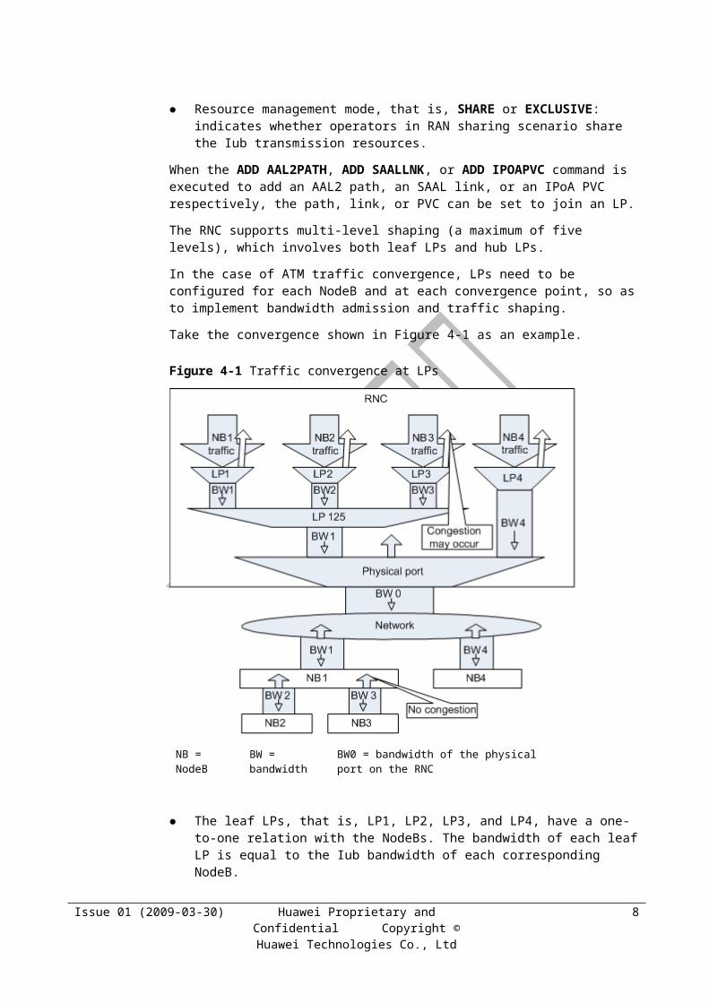
In the case of ATM traffic convergence, LPs need to be configured for each NodeB and at each convergence point, so as to implement bandwidth admission and traffic shaping.
Take the convergence shown in Figure 4-1 as an example.
Issue 01 (2009-03-30) Huawei Proprietary and Confidential Copyright © Huawei Technologies Co.,
Ltd
6
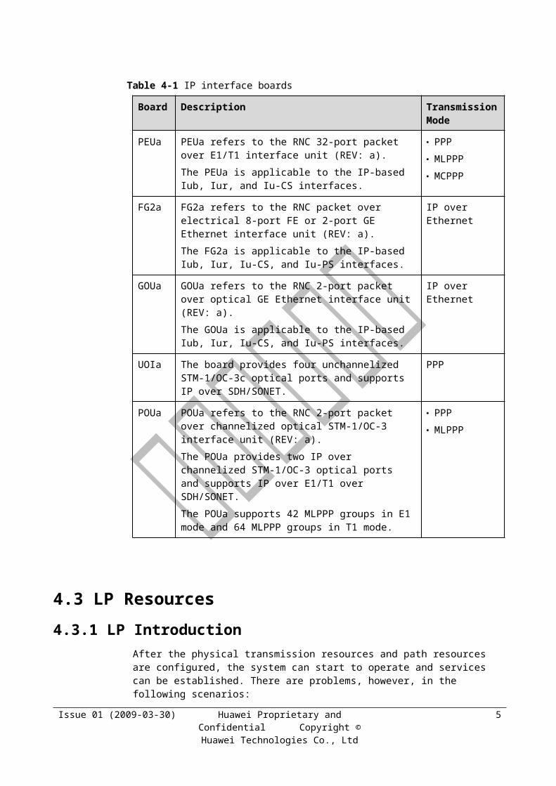
Figure 4-1 Traffic convergence at LPs
NB = NodeB BW = bandwidth BW0 = bandwidth of the physical port on the RNC
The leaf LPs, that is, LP1, LP2, LP3, and LP4, have a one-to-one relation with the NodeBs. The bandwidth of each leaf LP is equal to the Iub bandwidth of each corresponding NodeB.
The hub LP, that is, LP125, corresponds to the hub NodeB, and the LPs connected to the hub LP correspond to the NodeBs on the network. The bandwidth of the hub LP is equal to the Iub bandwidth of the hub NodeB.
The actual rate at a leaf LP is limited by the bandwidth of the leaf LP and the scheduling rate at the hub LP and physical port.
In the Call Admission Control (CAC) algorithm, the reserved bandwidth of a leaf LP is limited by not only the bandwidth of the leaf LP but also the bandwidth of the hub LP and the bandwidth of the physical port. That is, the total reserved bandwidth of all the LPs under a hub LP cannot exceed the bandwidth of the hub LP.
In RAN sharing scenario, an LP needs to be configured for each operator that uses the NodeB.
Table 4-1 describes the ATM LP capabilities of interface boards at the RNC.
Table 4-1 ATM LP capabilities of interface boards at the RNC
Board Number of LPs Level of LPs
AEUa Leaf LP: 0 to 127 Hub LP: 128 to 191
Five
AOUa Leaf LP: 0 to 255 Five
Issue 01 (2009-03-30) Huawei Proprietary and Confidential Copyright © Huawei Technologies Co.,
Ltd
7

Board Number of LPs Level of LPs
Hub LP: 256 to 383
UOIa_ATM Leaf LP: 0 to 383 Hub LP: 384 to 447
Five
4.3.3 IP LP at the RNCIP LPs have the functions of IP traffic shaping and bandwidth admission. They are configured on IP interface boards by running the ADD IPLOGICPORT command. These LPs have the following attributes:
Bandwidth: The downlink bandwidth is used for traffic shaping and bandwidth admission, and the uplink bandwidth is used for bandwidth admission only.
Resource management mode, that is, SHARE or EXCLUSIVE: indicates whether operators in RAN sharing scenario share the Iub transmission resources.
When the ADD IPPATH or ADD SCTPLNK command is executed to add an IP path or an SCTP link respectively, the path or link can be set to join an LP.
IP LPs are similar to ATM LPs in terms of principles and application. The current version of RAN supports only one level of IP LP.
Table 4-1 describes the IP LP capabilities of interface boards at the RNC.
Table 4-1 IP LP capabilities of interface boards at the RNC
Board Number of LPs
Level of Shaping
PEUa None One-level shaping at PPP or MLPPP ports
FG2a 0 to 119 Two-level shaping at LPs and Ethernet ports
GOUa 0 to 119 Two-level shaping at LPs and Ethernet ports
UOIa 0 to 119 One-level shaping at PPP ports
POUa None One-level shaping at PPP or MLPPP ports
4.3.4 Resource Group at the RNCResource groups have the bandwidth admission function but do not have the traffic shaping function. To add a resource group, run the ADD RSCGRP command.
4.3.5 ATM LP at the NodeBATM LPs at the NodeB have the function of ATM traffic shaping. To configure an ATM LP, run the ADD RSCGRP command to add an ATM resource group to the interface board at the NodeB. The LP has attributes such as the TX bandwidth, RX bandwidth, bearing port type, and bearing port number. The TX bandwidth is used for traffic shaping, and the RX bandwidth is used to calculate the remaining bandwidth for backpressure. Then, when the
Issue 01 (2009-03-30) Huawei Proprietary and Confidential Copyright © Huawei Technologies Co.,
Ltd
8

ADD AAL2PATH, ADD SAALLNK, or ADD OMCH command is executed to add an AAL2 path, an SAAL link, or an OM channel respectively, the path, link, or channel can be set to join an LP.
ATM LPs at the NodeB are mainly used to differentiate operators in RAN sharing scenario.
Each interface board of the NodeB supports a maximum of four ATM LPs.
4.3.6 IP LP at the NodeBIP LPs at the NodeB have the function of IP traffic shaping. To configure an IP LP, run the ADD RSCGRP command to add an IP resource group to the interface board at the NodeB. The LP has attributes such as the TX bandwidth, RX bandwidth, bearing port type, and bearing port number. The TX bandwidth is used for traffic shaping, and the RX bandwidth is used to calculate the remaining bandwidth for backpressure. Then, when the ADD IPPATH command is executed to add an IP path, that is, a path carrying the data traffic of the local NodeB, the path can be set to join an LP; when the ADD IP2RSCGRP command is executed, the signaling traffic and the forwarded data traffic can be set to join an LP.
IP LPs at the NodeB are mainly used to differentiate operators in RAN sharing scenario.
Each interface board of the NodeB supports a maximum of four IP LPs.
4.4 Path ResourcesPath resources involve those on the control plane, user plane, and management plane. The paths on the user plane, that is, AAL2 paths for ATM transport and IP paths for IP transport, are key resources. The allocation and management of transmission resources are based on paths.
4.4.1 AAL2 PathIn ATM transport mode, the following types of AAL2 path can be configured:
CBR
RT-VBR
NRT-VBR
UBR
UBR+
When an AAL2 path is configured, the TXTRFX and RXTRFX parameters need to be set. They determine the type of path. The traffic record indexes are configured by running the ADD ATMTRF command.
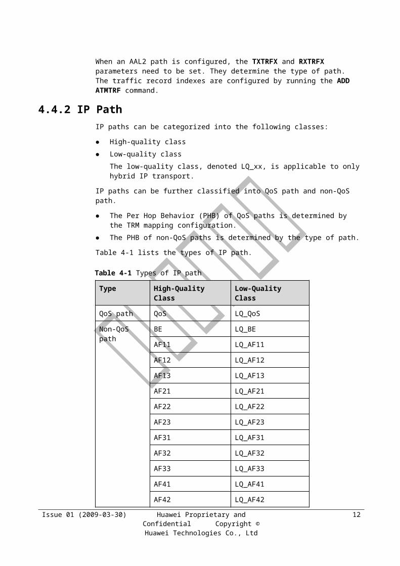
4.4.2 IP PathIP paths can be categorized into the following classes:
High-quality class
Low-quality class
The low-quality class, denoted LQ_xx, is applicable to only hybrid IP transport.
IP paths can be further classified into QoS path and non-QoS path.
Issue 01 (2009-03-30) Huawei Proprietary and Confidential Copyright © Huawei Technologies Co.,
Ltd
9
The Per Hop Behavior (PHB) of QoS paths is determined by the TRM mapping configuration.
The PHB of non-QoS paths is determined by the type of path.
Table 4-1 lists the types of IP path.
Table 4-1 Types of IP path
Type High-Quality Class Low-Quality Class
QoS path QoS LQ_QoS
Non-QoS path BE LQ_BE
AF11 LQ_AF11
AF12 LQ_AF12
AF13 LQ_AF13
AF21 LQ_AF21
AF22 LQ_AF22
AF23 LQ_AF23
AF31 LQ_AF31
AF32 LQ_AF32
AF33 LQ_AF33
AF41 LQ_AF41
AF42 LQ_AF42
AF43 LQ_AF43
EF LQ_EF
NOTE On the Iu-PS interface, even if IPoA transport is used, IP paths still need to be configured. HSDPA and HSUPA services can be carried on the same IP path, with HSDPA services in the
downlink and HSUPA services in the uplink.
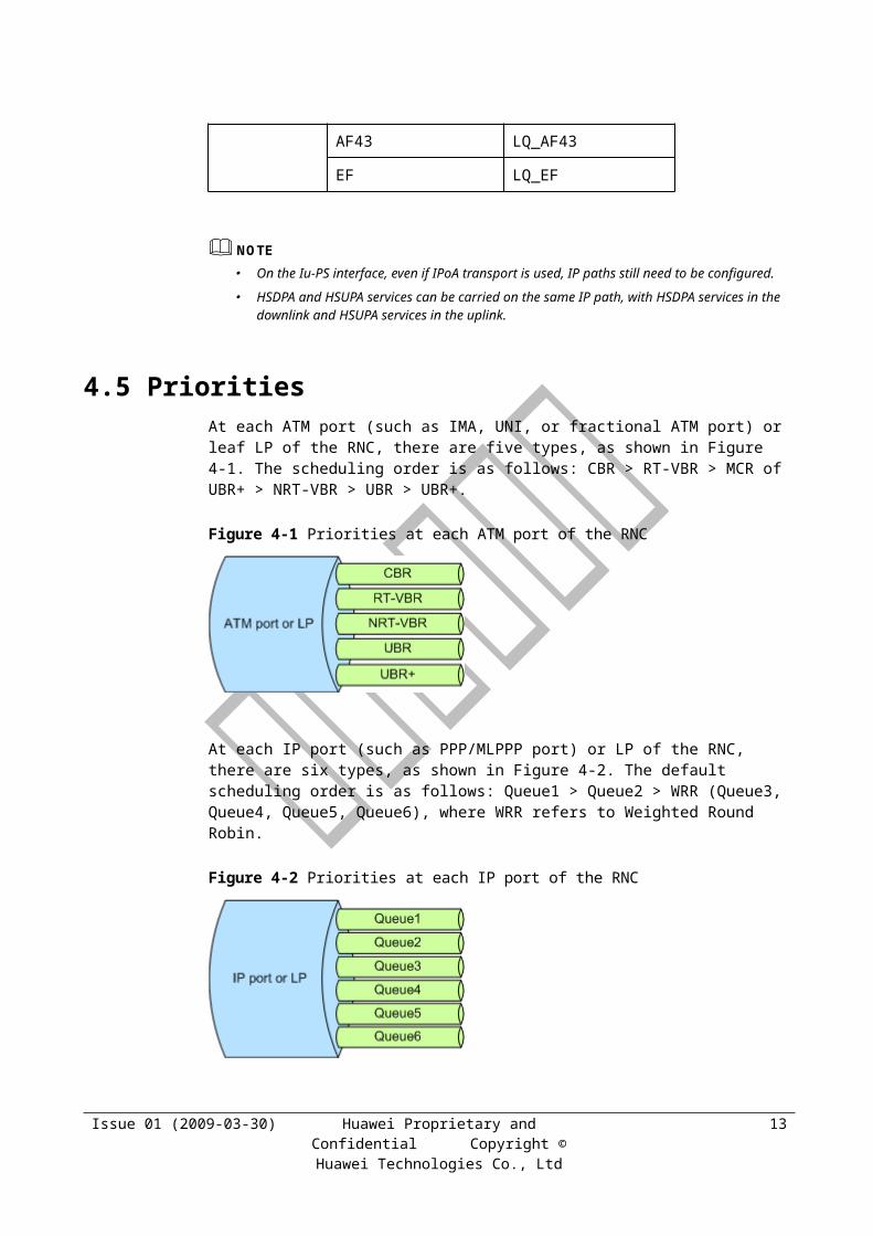
4.5 PrioritiesAt each ATM port (such as IMA, UNI, or fractional ATM port) or leaf LP of the RNC, there are five types, as shown in Figure 4-1. The scheduling order is as follows: CBR > RT-VBR > MCR of UBR+ > NRT-VBR > UBR > UBR+.
Issue 01 (2009-03-30) Huawei Proprietary and Confidential Copyright © Huawei Technologies Co.,
Ltd
10

Figure 4-1 Priorities at each ATM port of the RNC
At each IP port (such as PPP/MLPPP port) or LP of the RNC, there are six types, as shown in Figure 4-2. The default scheduling order is as follows: Queue1 > Queue2 > WRR (Queue3, Queue4, Queue5, Queue6), where WRR refers to Weighted Round Robin.
Figure 4-2 Priorities at each IP port of the RNC
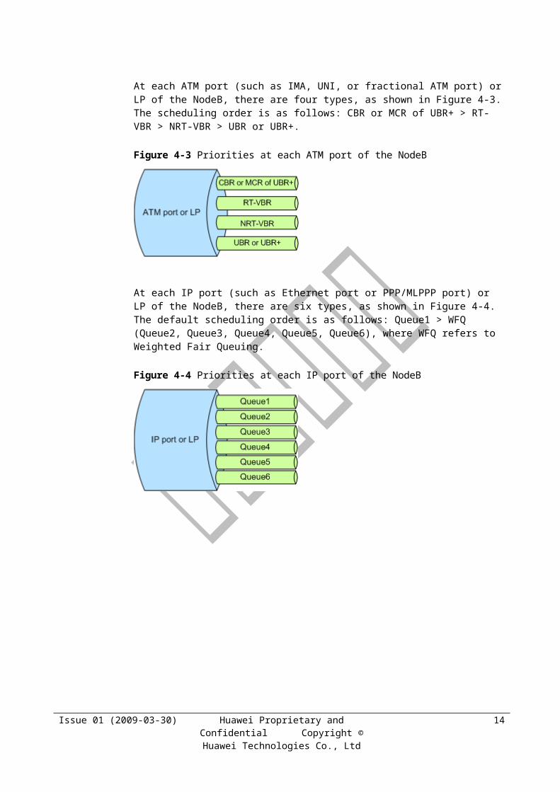
At each ATM port (such as IMA, UNI, or fractional ATM port) or LP of the NodeB, there are four types, as shown in Figure 4-3. The scheduling order is as follows: CBR or MCR of UBR+ > RT-VBR > NRT-VBR > UBR or UBR+.
Figure 4-3 Priorities at each ATM port of the NodeB
At each IP port (such as Ethernet port or PPP/MLPPP port) or LP of the NodeB, there are six types, as shown in Figure 4-4. The default scheduling order is as follows: Queue1 > WFQ (Queue2, Queue3, Queue4, Queue5, Queue6), where WFQ refers to Weighted Fair Queuing.
Issue 01 (2009-03-30) Huawei Proprietary and Confidential Copyright © Huawei Technologies Co.,
Ltd
11

Figure 4-4 Priorities at each IP port of the NodeB
Issue 01 (2009-03-30) Huawei Proprietary and Confidential Copyright © Huawei Technologies Co.,
Ltd
12
5 TRM Mapping
The transport network can provide differentiated QoS services, and the QoS requirements of traffic vary according to the traffic types. TRMMAP refers to the mapping from traffic bearers to transport bearers.
The RNC supports configuration of mapping to transport bearers according to the characteristics of traffic.
Figure 5-1 shows the TRM mapping.
Figure 5-1 TRM mapping
5.1 Traffic BearerThe prerequisite for TRM algorithms is the guarantee of QoS. Different types of service have different QoS requirements.
Issue 01 (2009-03-30) Huawei Proprietary and Confidential Copyright © Huawei Technologies Co.,
Ltd
1
For the Iub control plane and the Uu signaling, reliable transmission is required. The factors such as the frame loss rate and delay will affect KPIs such as the connection delay, handover success rate, access success rate, and call drop rate.
For R99 services, excessive delay and jitter must be avoided. Otherwise, the time window will be adjusted frequently.
For CS services, there are requirements for the delay and frame loss rate. For example, the end-to-end latency of voice services affects the Mean Opinion Score (MOS); Video Phone (VP) services are closely sensitive to packet loss.
BE services are relatively insensitive to the delay, but they still have delay specifications for ping commands. When the load is light, the delay requirement must be fulfilled. When the load is heavy, the delay requirement can be lowered to a certain extent so as to guarantee the throughput.
Traffic types are defined as follows:
From the narrow perspective, traffic types are determined by the traffic class at the radio network layer and the type of radio bearer.
From the broad perspective, traffic types are determined jointly by the traffic class, type of radio bearer, ARP, and THP. Traffic bearers are used to describe the traffic types in the broad sense only. These traffic types are further classified according to user priorities, for the purpose of better differentiated services.
The mapping from traffic types to transmission resources takes the following factors into consideration:
Traffic class at the radio network layer: conversational, streaming, interactive, and background, in descending order of QoS requirement.
The RNC provides the following traffic classes that can be used in TRMMAP configuration:
− Common channel
− SRB
− SIP
− AMR speech
− CS conversational
− CS streaming
− PS conversational
− PS streaming
− PS interactive
− PS background
Type of radio bearer: R99, HSDPA, and HSUPA. R99 bearers have certain requirements for the delay because of the time window mechanism. HSPA bearers, however, have relatively low requirements for the delay because of the absence of the time window mechanism on the Iub interface.
ARP: Even for traffic of the same type, the QoS requirements of different users vary. Thus, high-priority services may require high-QoS transport bearers at the transport layer.
THP: For interactive services, such as PS interactive services, THP parameters are available. There are three classes of THP: high, medium, and low.
Issue 01 (2009-03-30) Huawei Proprietary and Confidential Copyright © Huawei Technologies Co.,
Ltd
2
In summary, the inputs to TRMMAP are the traffic class, type of radio bearer, user priority and ARP, and THP. That is, each combination of these inputs corresponds to one priority of transport bearer.
5.2 Transport Bearer
5.2.1 Type of PathPaths are defined for the purpose of preventing the impact of different types of interface boards and different traffic queues at the physical layer. The transport bearer service refers to the service of transmitting traffic over paths of specific types. For path types, see section 4.4 "Path Resources."
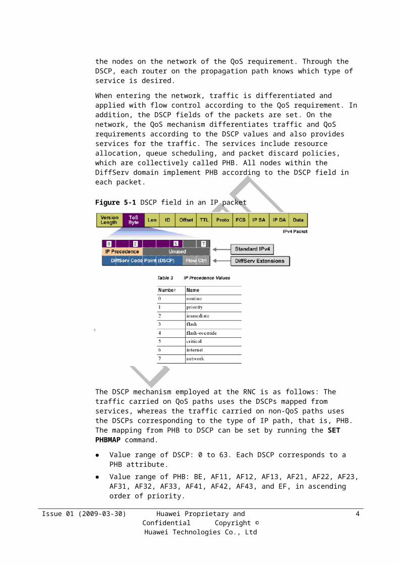
5.2.2 DiffServ and DSCPDifferentiated Services (DiffServ) is a key technology adopted in IP transport to improve the network QoS. The QoS information, that is, the Differentiated Services Code Point (DSCP), is carried in the header of each IP packet to inform the nodes on the network of the QoS requirement. Through the DSCP, each router on the propagation path knows which type of service is desired.
When entering the network, traffic is differentiated and applied with flow control according to the QoS requirement. In addition, the DSCP fields of the packets are set. On the network, the QoS mechanism differentiates traffic and QoS requirements according to the DSCP values and also provides services for the traffic. The services include resource allocation, queue scheduling, and packet discard policies, which are collectively called PHB. All nodes within the DiffServ domain implement PHB according to the DSCP field in each packet.
Figure 5-1 DSCP field in an IP packet
The DSCP mechanism employed at the RNC is as follows: The traffic carried on QoS paths uses the DSCPs mapped from services, whereas the traffic carried on non-QoS paths uses the
Issue 01 (2009-03-30) Huawei Proprietary and Confidential Copyright © Huawei Technologies Co.,
Ltd
3
DSCPs corresponding to the type of IP path, that is, PHB. The mapping from PHB to DSCP can be set by running the SET PHBMAP command.
Value range of DSCP: 0 to 63. Each DSCP corresponds to a PHB attribute.
Value range of PHB: BE, AF11, AF12, AF13, AF21, AF22, AF23, AF31, AF32, AF33, AF41, AF42, AF43, and EF, in ascending order of priority.
QoS paths are recommended, because of simple configuration and better implementation of multiplexing, QoS guarantee, and service differentiation.
5.3 Mapping from Traffic Bearers to Transport Bearers
For the mapping from traffic bearers to transport bearers, both the default configuration and the adjacent-node-oriented configuration are available.
The keyword used for configuring TRMMAP is the traffic type, that is, the combination of traffic class, type of radio bearer, and THP. Primary and secondary paths can be configured. For details about primary and secondary paths, see section 6.3 "Admission Control."
5.3.1 RNC-Oriented Default MappingThe RNC provides default mapping tables with IDs from 0 to 8 for Iub ATM, Iub IP, Iub ATM&IP, Iub hybrid IP, Iur ATM, Iur IP, Iu-CS ATM, Iu-CS IP, and Iu-PS respectively. These tables can only be queried by running the LST TRMMAP command.
Table 5-1 lists the default TRMMAP tables.
Table 5-1 Default TRMMAP tables
Interface ATM IP ATM&IP
Hybrid IP
Iub 0 1 2 3
Iur 4 5
Iu-CS 6 7
Iu-PS 8
NOTE
The RNC-oriented default TRM mapping is not specific for operators or user priorities. If no adjacent-node-oriented mapping is configured, the RNC-oriented default TRM mapping applies.
Configuration of TRM Mapping
For details, see chapter 10 "Appendix."
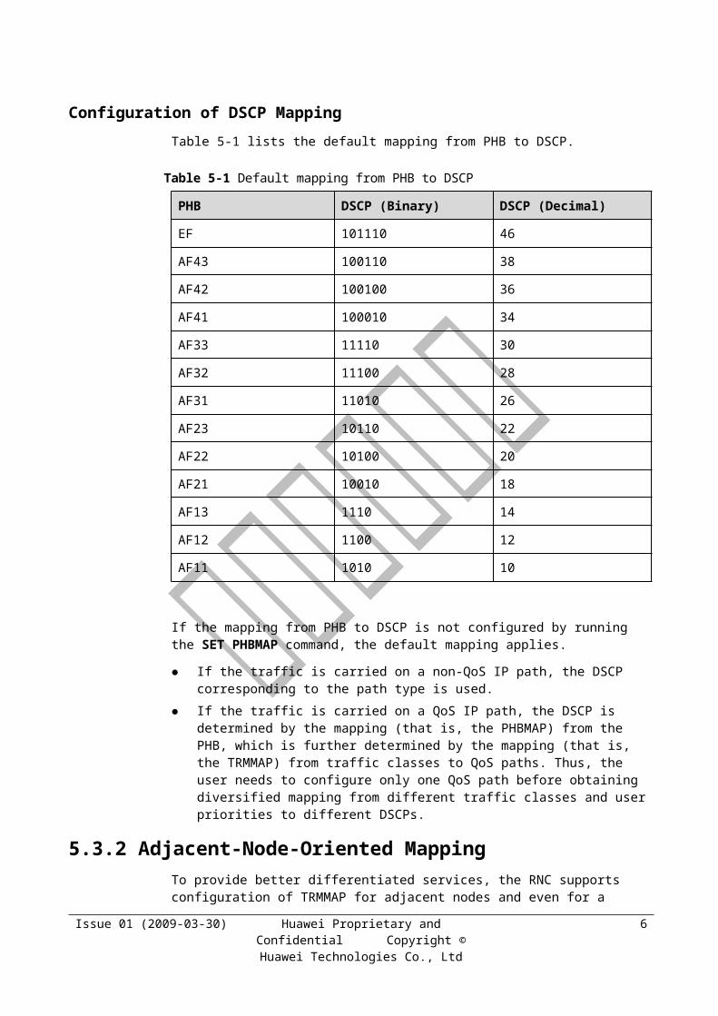
Configuration of DSCP Mapping
Table 5-1 lists the default mapping from PHB to DSCP.
Issue 01 (2009-03-30) Huawei Proprietary and Confidential Copyright © Huawei Technologies Co.,
Ltd
4
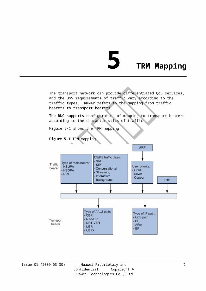
Table 5-1 Default mapping from PHB to DSCP
PHB DSCP (Binary) DSCP (Decimal)
EF 101110 46
AF43 100110 38
AF42 100100 36
AF41 100010 34
AF33 11110 30
AF32 11100 28
AF31 11010 26
AF23 10110 22
AF22 10100 20
AF21 10010 18
AF13 1110 14
AF12 1100 12
AF11 1010 10
If the mapping from PHB to DSCP is not configured by running the SET PHBMAP command, the default mapping applies.
If the traffic is carried on a non-QoS IP path, the DSCP corresponding to the path type is used.
If the traffic is carried on a QoS IP path, the DSCP is determined by the mapping (that is, the PHBMAP) from the PHB, which is further determined by the mapping (that is, the TRMMAP) from traffic classes to QoS paths. Thus, the user needs to configure only one QoS path before obtaining diversified mapping from different traffic classes and user priorities to different DSCPs.
5.3.2 Adjacent-Node-Oriented MappingTo provide better differentiated services, the RNC supports configuration of TRMMAP for adjacent nodes and even for a specific operator and a specific user priority at a specific adjacent node. This helps achieve flexible configuration of mapping from traffic bearers to transport bearers.
To configure the mapping for an adjacent node, perform the following steps:
Step 1 Run the ADD TRMMAP command to specify the mapping from the traffic classes of a specific interface type and transport type to the transport bearers.
Step 2 Run the ADD ADJMAP command to reference the configured TRMMAP tables for the adjacent node. In this step, the TRMMAP tables need to be individually specified for Gold, Silver, and Copper users.
Issue 01 (2009-03-30) Huawei Proprietary and Confidential Copyright © Huawei Technologies Co.,
Ltd
5
NOTE
In RAN sharing scenario, if the resource management mode is set to EXCLUSIVE, the operator index needs to be set so as to specify the TRMMAP for the users of that operator at the adjacent node.
The related commands are ADD TRMMAP, MOD TRMMAP, ADD ADJMAP, and MOD ADJMAP.
----End
Issue 01 (2009-03-30) Huawei Proprietary and Confidential Copyright © Huawei Technologies Co.,
Ltd
6
6 Load Control
The load control algorithm allocates transmission resources to services, manages the transmission bandwidth, and controls the transmission load for the purpose of allowing access of users to the maximum extent without affecting the QoS.
6.1 Definition of LoadThe load control algorithm is implemented at the RNC, and therefore, the load is defined and measured at the RNC. The definition of load is based on the reserved bandwidth. The load control algorithm reserves bandwidth for each service. The load refers to the sum of bandwidth reserved for all services. The uplink load and downlink load are calculated separately.
The load of each path and that of each LP (including leaf LP and hub LP) need to be calculated. The load definitions are as follows:
Load of a path: sum of bandwidth reserved for all services on the path
Load of a leaf LP: total load of all paths carried on the LP
Load of hub LP: total load of all LPs under the hub LP
6.2 Bandwidth Reserved for ServicesThe load is defined on the basis of the bandwidth reserved for each service. Therefore, the method of calculating the bandwidth reserved for each type of service must be provided.
Bandwidth reserved for a service = Transport-layer rate of the service x Activity factor, where the transport-layer rate of the service derives from the rate that the user applies for.
The RNC calculates the reserved bandwidth based on the activity factor and performs admission control based on the reserved bandwidth, thus enabling Iub overbooking, that is, allowing admission of more services to the bandwidth. The more the services admitted, the higher the statistical multiplexing gain.
After activity factors are taken into consideration, a larger number of users can access the network over the Iub interface. In this case, however, the Iub congestion probability increases accordingly. If all services are transmitted at the rate higher than their respective admission bandwidth at the same time, congestion and packet loss occur on the Iub interface. Then, the user experience deteriorates and the Iub bandwidth usage decreases. To solve the possible congestion problem, the Iub interface requires the related congestion control algorithm. For details, see section 7.3 "Congestion Control of Iub User Plane."
Issue 01 (2009-03-30) Huawei Proprietary and Confidential Copyright © Huawei Technologies Co.,
Ltd
1
The following bandwidth reservation policies apply:
RT services, including conversational and streaming services, are admitted at the Maximum Bit Rate (MBR).
− The bandwidth for RT services must be guaranteed. RT services do not allow packet loss or large-volume data buffering.
− The activity of RT services follows an obvious rule. When multiple services access the network, the total actual traffic volume is relatively stable. The appropriate setting of activity factors can help achieve correct admission of the services.
− RT services should be admitted on the basis of the average actual traffic volume, so that the number of users allowed to access the network can be increased to the maximum extent under the condition that the QoS is guaranteed.
− Reserved bandwidth for admission of an RT service = MBR x Activity factor, where the activity factor needs to be set for each type of service.
NRT services, including interactive and background services, are admitted at the GBR.
− NRT services do not have strict requirements for bandwidth guarantee. When resources are insufficient, the traffic throughput can be lowered at the application layer through data buffering, to which the application layer can be adaptive.
− The activity of NRT services does not follow any obvious rule. When multiple services access the network, the total actual traffic volume fluctuates greatly. Therefore, it is difficult to estimate the exact bandwidth used by NRT services.
− If a large number of users access the network, the bandwidth efficiency is improved to a certain extent, but congestion and packet loss occur. If a small number of users access the network, the bandwidth efficiency is low.
− If no appropriate user plane congestion control algorithm is available for preventing congestion and packet loss, the services should be admitted at the MBR multiplied by the activity factor. The MBR, however, needs to be adjusted frequently in the interests of high bandwidth efficiency and a large number of users accessing the network. Thus, a complicated user plane load algorithm is required.
− Huawei has developed a complete user plane congestion control algorithm, in which the only condition of transmission admission is to provide GBR guarantee for users. The principle is to allow access of users to the maximum extent under the condition that the GBR is guaranteed. That is, the admission algorithm can reserve the bandwidth for users based on the GBR.
In terms of 3G signaling, SRB services can be admitted at either the GBR or 3.4 Kbit/s.
− Admission at 3.4 Kbit/s: The bandwidth is fixed at 3.4 Kbit/s. This admission mode is applicable to R99, HSDPA, and HSUPA services.
− Admission at the GBR: For R99 services, if the bandwidth of a transport channel varies between 3.4 Kbit/s and 13.6 Kbit/s, resource allocation and resource admission do not need to be performed again.
In terms of common channels, EFACH services are admitted at the GBR, and other common channel services are admitted at the MBR.
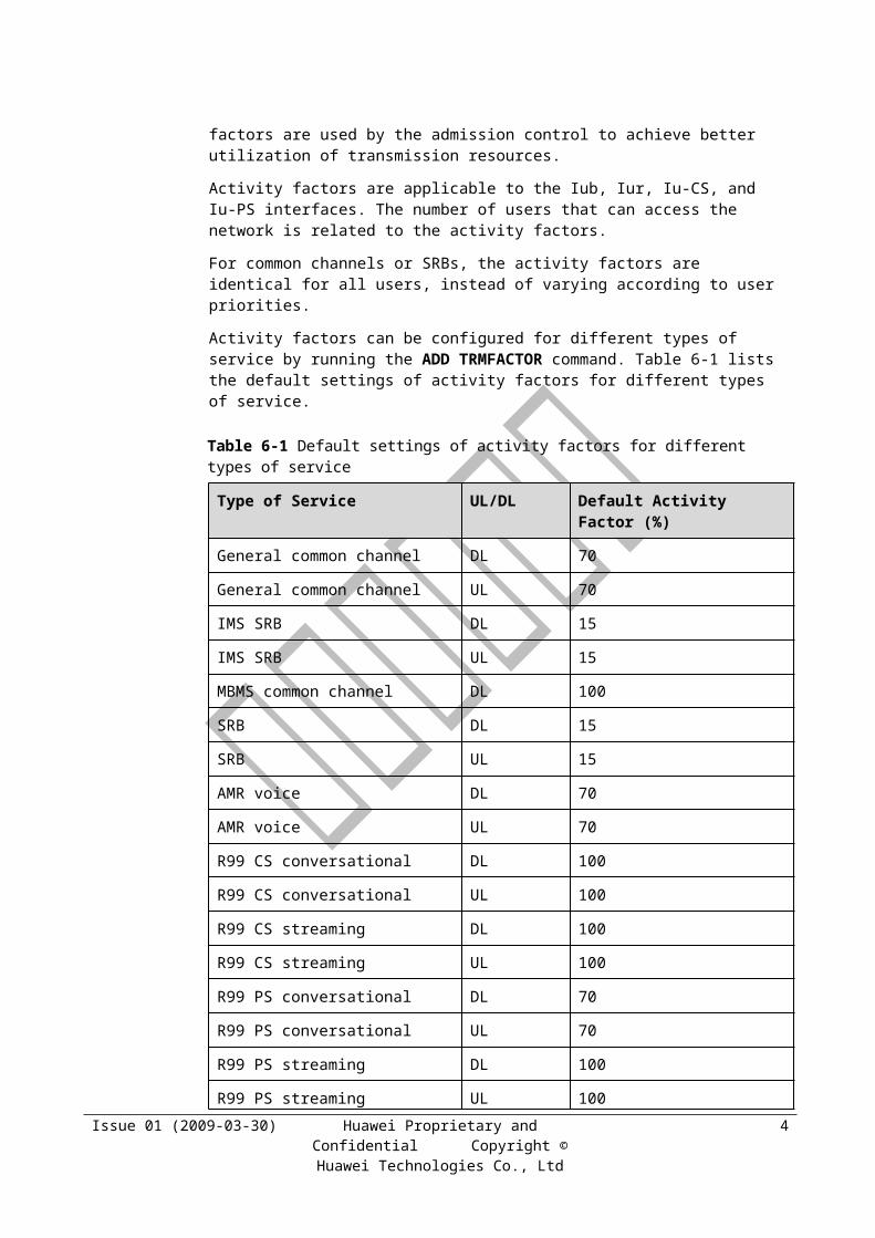
Because of the discontinuity of traffic, there are active periods, during which data is transmitted, and inactive periods, during which data is not transmitted. Activity factors are used by the admission control to achieve better utilization of transmission resources.
Activity factors are applicable to the Iub, Iur, Iu-CS, and Iu-PS interfaces. The number of users that can access the network is related to the activity factors.
For common channels or SRBs, the activity factors are identical for all users, instead of varying according to user priorities.
Issue 01 (2009-03-30) Huawei Proprietary and Confidential Copyright © Huawei Technologies Co.,
Ltd
2
Activity factors can be configured for different types of service by running the ADD TRMFACTOR command. Table 6-1 lists the default settings of activity factors for different types of service.
Table 6-1 Default settings of activity factors for different types of service
Type of Service UL/DL Default Activity Factor (%)
General common channel DL 70
General common channel UL 70
IMS SRB DL 15
IMS SRB UL 15
MBMS common channel DL 100
SRB DL 15
SRB UL 15
AMR voice DL 70
AMR voice UL 70
R99 CS conversational DL 100
R99 CS conversational UL 100
R99 CS streaming DL 100
R99 CS streaming UL 100
R99 PS conversational DL 70
R99 PS conversational UL 70
R99 PS streaming DL 100
R99 PS streaming UL 100
R99 PS interactive DL 100
R99 PS interactive UL 100
R99 PS background DL 100
R99 PS background UL 100
HSDPA SRB DL 50
HSDPA IMS SRB DL 15
HSDPA voice DL 70
HSDPA conversational DL 70
HSDPA streaming DL 100
HSDPA interactive DL 100
Issue 01 (2009-03-30) Huawei Proprietary and Confidential Copyright © Huawei Technologies Co.,
Ltd
3
Type of Service UL/DL Default Activity Factor (%)
HSDPA background DL 100
HSUPA SRB UL 50
HSUPA IMS SRB UL 15
HSUPA voice UL 70
HSUPA conversational UL 70
HSUPA streaming UL 100
HSUPA interactive UL 100
HSUPA background UL 100
EFACH channel DL 20
When the adjacent-node-oriented mapping is added or modified by running the ADD ADJMAP or MOD ADJMAP command respectively, the activity factor table to be referenced can be specified by the FTI parameter.
For BE services, the GBR can be set by running the SET USERGBR command. The associated parameters are as follows:
TrafficClass
THPClass
BearType
UserPriority
UlGBR
DlGBR
6.3 Admission ControlAdmission control is used to determine whether the system resources are sufficient for the network to accept the access request of a new user. If the system resources are sufficient, the access request is accepted; otherwise, the request is rejected.
6.3.1 Admission Control AlgorithmThe admission policy varies according to the type of user.
For a new user, the following requirements apply:
− Admission to a path:
Load of the path + Bandwidth required by the user < Total configured bandwidth of the path – Bandwidth reserved for handover
− Admission to an LP: (The admission to LPs should be performed level by level. The following requirement is applicable to each level of LP.)
Issue 01 (2009-03-30) Huawei Proprietary and Confidential Copyright © Huawei Technologies Co.,
Ltd
4

Load of the LP + Bandwidth required by the user < Total bandwidth of the LP – Bandwidth reserved for handover
For handover of a user, the following requirements apply:
− Admission to a path:
Load of the path + Bandwidth required by the user < Total configured bandwidth of the path
− Admission to an LP: (The admission to LPs should be performed level by level. The following requirement is applicable to each level of LP.)
Load of the LP + Bandwidth required by the user < Total bandwidth of the LP
For rate upsizing of a user, the following requirements apply:
− Admission to a path:
Load of the path + Bandwidth required by the user < Total configured bandwidth of the path – Congestion threshold
− Admission to an LP: (The admission to LPs should be performed level by level. The following requirement is applicable to each level of LP.)
Load of the LP + Bandwidth required by the user < Total bandwidth of the LP – Congestion threshold
NOTE For a path that belongs to a path group, admission control must be performed at both the path level
and the path group level. For an IMA group or MLPPP group, the RNC automatically adjusts the maximum bandwidth
available to the whole group and uses the new admission threshold if the bandwidth of an IMA link or MLPPP link changes.
Bandwidth reserved for handover ≤ Congestion threshold ≤ Congestion resolving threshold
The congestion threshold and the congestion resolving threshold are used to prevent the ping-pong effect.
Based on the preceding requirement, the user priorities are as follows:
User requesting handover > New user > User requesting rate upsizing
The congestion thresholds are FWDCONGBW and BWDCONGBW, and the congestion resolving thresholds are FWDCONGCLRBW and BWDCONGCLRBW.
The parameters that are used to reserve bandwidth for handover are as follows:
FWDHORSVBW
BWDHORSVBW
6.3.2 Load BalancingIn the admission control mechanism, load balancing is an algorithm used to achieve the load balance between primary and secondary paths. A service is not always preferably admitted to the primary path. If the load of the primary path exceeds its load threshold and the ratio of primary path load to secondary path load is higher than the load ratio threshold, then the service is preferably admitted to the secondary path, so as to improve the resource usage and user experience.
The load of a path is calculated as follows:
PathLoad = PortUsed ÷ PortAvailable x 100%
Issue 01 (2009-03-30) Huawei Proprietary and Confidential Copyright © Huawei Technologies Co.,
Ltd
5
where:
PathLoad refers to the load of the path.
PortUsed refers to the total bandwidth of the admitted services at the physical port.
PortAvailable refers to the total available bandwidth at the physical port, including the used bandwidth.
When the primary path for a type of service exists at more than one physical port, PortUsed and PortAvailable refer to the sum of used bandwidth and the sum of available bandwidth at these ports respectively.
Load balancing tables can be configured by running the ADD LOADEQ command. Each table contains primary path load thresholds and primary-to-secondary path load ratio thresholds. The combination of a primary path load threshold and a path load ratio threshold can vary depending on the traffic type. In addition, the ARP needs to be taken into consideration. After the load balancing tables are configured, they can be referenced when load balancing parameters need to be set for ATM&IP- or hybrid-IP-based Iub adjacent nodes by running the ADD ADJMAP or MOD ADJMAP command.
The load balancing application policy is similar to the TRMMAP policy. If the reference for load balancing tables is not set for the adjacent node, the default load balancing table applies. The table with the index 0 is the default one. It can only be queried by running the LST LOADEQ command.
Table 6-1 lists the default settings of load and load ratio thresholds for different types of service.
Table 6-1 Default settings of load and load ratio thresholds for different types of service
Threshold Default Value
Primary path load threshold for common channel 100
Primary-to-secondary path load ratio threshold for common channel 0
Primary path load threshold for IMS SRB 100
Primary-to-secondary path load ratio threshold for IMS SRB 0
Primary path load threshold for SRB 100
Primary-to-secondary path load ratio threshold for SRB 0
Primary path load threshold for AMR voice 100
Primary-to-secondary path load ratio threshold for AMR voice 0
Primary path load threshold for R99 CS conversational 100
Primary-to-secondary path load ratio threshold for R99 CS conversational
0
Primary path load threshold for R99 CS streaming 100
Primary-to-secondary path load ratio threshold for R99 CS streaming 0
Primary path load threshold for R99 PS conversational 100
Primary-to-secondary path load ratio threshold for R99 PS 0
Issue 01 (2009-03-30) Huawei Proprietary and Confidential Copyright © Huawei Technologies Co.,
Ltd
6
Threshold Default Value
conversational
Primary path load threshold for R99 PS streaming 100
Primary-to-secondary path load ratio threshold for R99 PS streaming 0
Primary path load threshold for R99 PS high-priority interactive 30
Primary-to-secondary path load ratio threshold for R99 PS high-priority interactive
100
Primary path load threshold for R99 PS medium-priority interactive 30
Primary-to-secondary path load ratio threshold for R99 PS medium-priority interactive
100
Primary path load threshold for R99 PS low-priority interactive 30
Primary-to-secondary path load ratio threshold for R99 PS low-priority interactive
100
Primary path load threshold for R99 PS background 30
Primary-to-secondary path load ratio threshold for R99 PS background
100
Primary path load threshold for HSDPA SRB 100
Primary-to-secondary path load ratio threshold for HSDPA SRB 0
Primary path load threshold for HSDPA IMS SRB 100
Primary-to-secondary path load ratio threshold for HSDPA IMS SRB 0
Primary path load threshold for HSDPA conversational 100
Primary-to-secondary path load ratio threshold for HSDPA conversational
0
Primary path load threshold for HSDPA streaming 100
Primary-to-secondary path load ratio threshold for HSDPA streaming 0
Primary path load threshold for HSDPA high-priority interactive 30
Primary-to-secondary path load ratio threshold for HSDPA high-priority interactive
100
Primary path load threshold for HSDPA medium-priority interactive 30
Primary-to-secondary path load ratio threshold for HSDPA medium-priority interactive
100
Primary path load threshold for HSDPA low-priority interactive 30
Primary-to-secondary path load ratio threshold for HSDPA low-priority interactive
100
Primary path load threshold for HSDPA background 30
Issue 01 (2009-03-30) Huawei Proprietary and Confidential Copyright © Huawei Technologies Co.,
Ltd
7
Threshold Default Value
Primary-to-secondary path load ratio threshold for HSDPA background
100
Primary path load threshold for HSUPA SRB 100
Primary-to-secondary path load ratio threshold for HSUPA SRB 0
Primary path load threshold for HSUPA IMS SRB 100
Primary-to-secondary path load ratio threshold for HSUPA IMS SRB 0
Primary path load threshold for HSUPA conversational 100
Primary-to-secondary path load ratio threshold for HSUPA conversational
0
Primary path load threshold for HSUPA streaming 100
Primary-to-secondary path load ratio threshold for HSUPA streaming 0
Primary path load threshold for HSUPA high-priority interactive 30
Primary-to-secondary path load ratio threshold for HSUPA high-priority interactive
100
Primary path load threshold for HSUPA medium-priority interactive 30
Primary-to-secondary path load ratio threshold for HSUPA medium-priority interactive
100
Primary path load threshold for HSUPA low-priority interactive 30
Primary-to-secondary path load ratio threshold for HSUPA low-priority interactive
100
Primary path load threshold for HSUPA background 30
Primary-to-secondary path load ratio threshold for HSUPA background
100
6.3.3 Admission ProcedurePrimary and secondary paths are used in admission control. According to the mapping from traffic types to transmission resources, the RNC calculates the load of the primary and secondary paths and then determines whether to select the primary or secondary path as the preferred path for admission based on the settings of the primary path load threshold and primary-to-secondary path load ratio threshold. If the admission to the preferred path fails, then the admission to the non-preferred path is performed. For details about the mapping from traffic types to transmission resources, see chapter 5 "TRM Mapping."
For example, assume that secondary paths are available for new users, handover of users, and rate upsizing of users and that the RNC selects primary paths as preferred paths for admission of the new users and handover of users (the procedures of admission with secondary paths
Issue 01 (2009-03-30) Huawei Proprietary and Confidential Copyright © Huawei Technologies Co.,
Ltd
8
preferred are the same). The following procedures describe the admission of these users on the Iub interface respectively.
The admission procedure for a new user is as follows:
Step 1 The new user attempts to be admitted to available bandwidth 1 on the primary path, as shown in Figure 6-1.
Step 2 If the user succeeds in applying for the resources on the primary path, the user is admitted to the primary path.
Step 3 If the user fails to apply for the resources on the primary path, the user then attempts to be admitted to available bandwidth 2 on the secondary path, as shown in Figure 6-1.
Step 4 If the user succeeds in applying for the resources on the secondary path, the user is admitted to the secondary path. If the user fails, the bandwidth admission request of the user is rejected.
----End
Figure 6-1 Admission procedure for a new user
Available bandwidth 1 = Total bandwidth of the primary path – Used bandwidth – Bandwidth reserved for handoverAvailable bandwidth 2 = Total bandwidth of the secondary path – Used bandwidth – Bandwidth reserved for handover
The admission procedure for handover of a user is as follows:
Step 1 The user attempts to be admitted to available bandwidth 1 on the primary path, as shown in Figure 6-1.
Step 2 If the user succeeds in applying for the resources on the primary path, the user is admitted to the primary path.
Step 3 If the user fails to apply for the resources on the primary path, the user then attempts to be admitted to available bandwidth 2 on the secondary path, as shown in Figure 6-1.
Step 4 If the user succeeds in applying for the resources on the secondary path, the user is admitted to the secondary path. If the user fails, the bandwidth admission request of the user is rejected.
----End
Issue 01 (2009-03-30) Huawei Proprietary and Confidential Copyright © Huawei Technologies Co.,
Ltd
9

Figure 6-1 Admission procedure for handover of a user
Available bandwidth 1 = Total bandwidth of the primary path - Used bandwidthAvailable bandwidth 2 = Total bandwidth of the secondary path - Used bandwidth
The admission procedure for rate upsizing of a user is as follows:
Step 1 The user attempts to be admitted to available bandwidth 1 on the bearing path of the user (that is, the primary path in this example), as shown in Figure 6-1.
Step 2 If the rate upsizing on the bearing path is successful, the traffic of the user is still carried on the path.
Step 3 If the rate upsizing on the bearing path fails, the user attempts to be admitted to available bandwidth 2 on the preferred path (that is, the secondary path in this example, as determined by the load balancing algorithm), as shown in Figure 6-1.
Step 4 If the user succeeds in applying for the resources on the preferred path, the user is admitted to the preferred path. If the user fails, it attempts to be admitted to the non-preferred path (that is, another primary path in this example).
Step 5 If the rate upsizing on the non-preferred path is successful, the user is admitted to the non-preferred path. Otherwise, the rate upsizing of the user fails.
----End
Figure 6-1 Admission procedure for rate upsizing of a user
Available bandwidth 1 = Total bandwidth of the primary path – Used bandwidth – Bandwidth reserved against congestionAvailable bandwidth 2 = Total bandwidth of the secondary path – Used bandwidth – Bandwidth reserved against congestion
Issue 01 (2009-03-30) Huawei Proprietary and Confidential Copyright © Huawei Technologies Co.,
Ltd
10
NOTE
If no secondary paths are available for the users, the admission is performed only on the primary paths.
6.4 Intelligent Access ControlIntelligent Access Control (IAC) is aimed at improving the access success rate. IAC involves the following procedures: rate negotiation, CAC, pre-emption, queuing, and Directed Retry Decision (DRD).
For details about IAC, see the Load Control Parameter Description.
6.5 Load Reshuffling and Overload ControlWhen the usage of cell resources exceeds the basic-congestion threshold, the cell enters the basic congestion state. In this case, Load Reshuffling (LDR) is required to reduce the cell load and increase the access success rate.
The following four resources can trigger the basic congestion of a cell: power resource, code resource, Iub resources, and NodeB credit resource. This section describes only the Iub resources. For details about other resources, see the Load Control Parameter Description.
LDR involves the following algorithms:
Iub Congestion Detection
Iub Overload Detection
Congestion and Overload Handling
6.5.1 Iub Congestion DetectionFor a path, port, or resource group, the following congestion-related parameters are applicable:
Congestion detection parameters:
− FWDCONGBW
− BWDCONGBW
The default values of the two parameters are 0, which indicates that no congestion detection will be performed. If the parameters are set to values other than 0, TRM performs congestion detection according to the settings.
Congestion resolving parameters:
− FWDCONGCLRBW
− BWDCONGCLRBW
These two parameters are used to determine whether the congestion is resolved.
Congestion detection can be triggered in any of the following conditions:
Bandwidth adjustment because of resource allocation, modification, or release
Change in the configured bandwidth or the congestion threshold
Fault in the physical link
Assume that the forward parameters of a port for congestion detection are defined as follows:
Issue 01 (2009-03-30) Huawei Proprietary and Confidential Copyright © Huawei Technologies Co.,
Ltd
11

Configured bandwidth: AVE
Forward congestion threshold: CON
Forward congestion resolving threshold: CLEAR (Note that CLEAR is greater than CON.)
Used bandwidth: USED
Then, the mechanism of congestion detection for the port is as follows:
Congestion occurs on the port when CON + USED ≥ AVE.
Congestion disappears from the port when CLEAR + USED < AVE.
The congestion detection for a path or a resource group is similar to that for a port.
Generally, congestion thresholds need to be set for only ports or resource groups. If different types of AAL2 paths or IP paths require different congestion thresholds, the associated parameters need to be set for the paths as required.
If ATM LPs or IP LPs are configured, congestion control is also applicable to the LPs. The congestion detection mechanism for the LPs is the same as that for resource groups.
6.5.2 Iub Overload DetectionOverload can be triggered in any of the following conditions:
In ATM IMA networking scenario, an IMA group contains multiple E1s, among which some E1s are broken whereas others work properly.
In ADSL networking scenario, the available ADSL bandwidth deteriorates abruptly, for example, from 8 Mbit/s to 1 Mbit/s.
Some links in a link aggregation group are faulty, and thus the available bandwidth of the group decreases.
Some links in an IP MLPPP group are faulty, and thus the available bandwidth of the group decreases.
Similar to congestion detection, overload detection is applicable to paths, resource groups, and ports.
For example: Assume the available bandwidth at a port as AVE and the used bandwidth at the port as USED. Then, overload occurs when USED > AVE.
6.5.3 Congestion and Overload Handling
Handling on the Iub Interface
If IUB_LDR under the NodeBLdcAlgoSwitch parameter is set to 1 by running the ADD NODEBALGOPARA or MOD NODEBALGOPARA command,
After the RNC receives a congestion message, the RNC triggers LDR actions. For details about the LDR actions, see the Load Control Parameter Description.
After the RNC receives an overload message, the RNC triggers Overload Control (OLC) actions. OLC triggers release of resources used by users in order of comprehensive priority.
Issue 01 (2009-03-30) Huawei Proprietary and Confidential Copyright © Huawei Technologies Co.,
Ltd
12
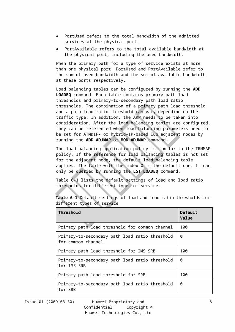
Handling on Other Interfaces The congestion on the Iur interface can trigger Serving Radio Network Subsystem
(SRNS) relocation. For details about SRNS relocation, see the SRNS Relocation Parameter Description.
During Iu signaling flow control, if congestion is detected on the signaling link towards the signaling point, the congested state is reported to the RANAP subsystem of the RNC. Then, the RANAP subsystem discards user messages in the following sequence: short message service > CS and PS call > registration.
Issue 01 (2009-03-30) Huawei Proprietary and Confidential Copyright © Huawei Technologies Co.,
Ltd
13
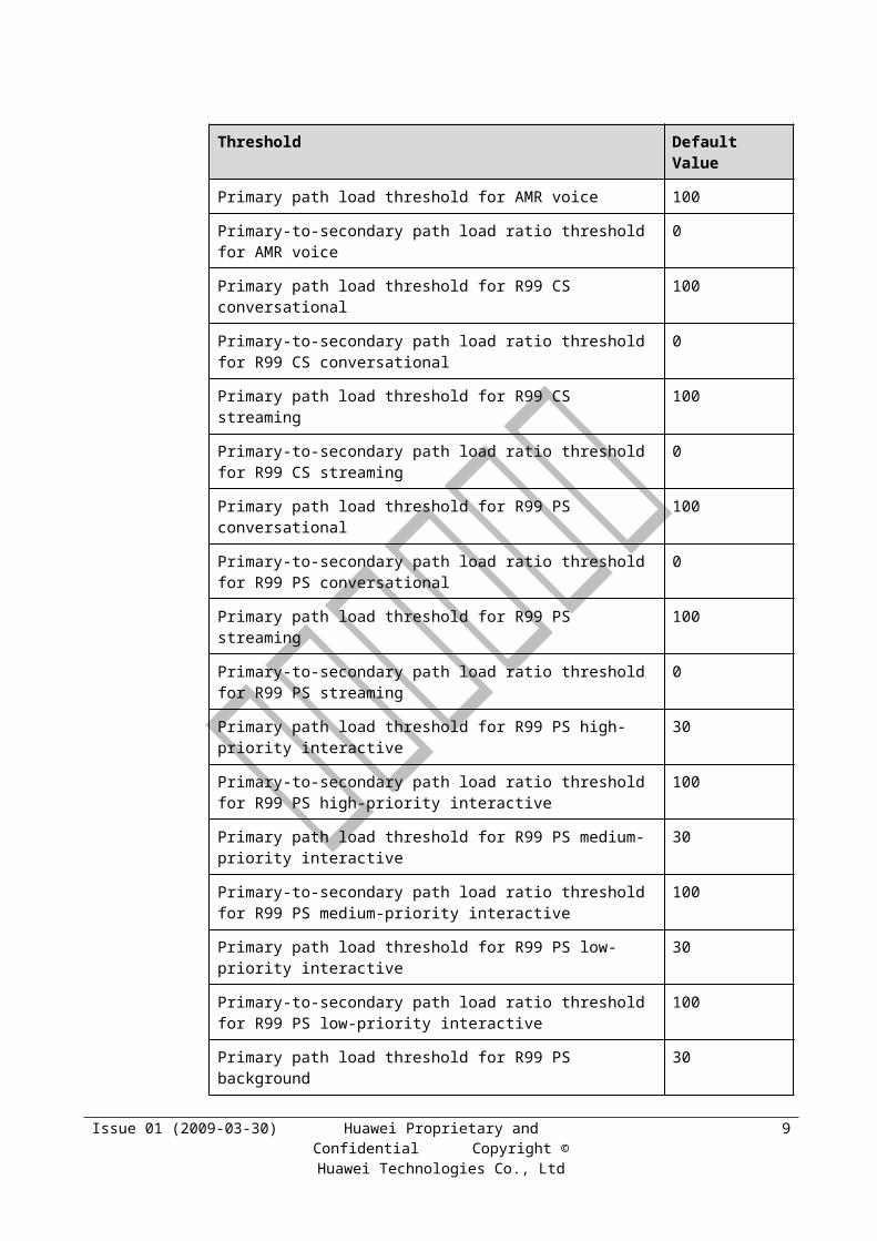
7 User Plane Processing
7.1 Overview of User Plane ProcessingThe load control algorithm described in the previous chapter is based on the bandwidth reserved for services. It does not involve the actual processing procedure. This chapter describes the algorithm for user plane processing. It consists of the following contents:
Hub scheduling and shaping: consists of RNC scheduling and shaping and NodeB scheduling and shaping. Scheduling is performed to guarantee fairness between NodeBs in the convergence scenario. Shaping refers to Logical Port (LP) shaping. Shaping is performed to control the total transmission rate of the RNC and NodeB to prevent congestion on the transport network.
Congestion control: controls the transmission rate of the NRT service, prevents congestion due to packet loss on the Iub interface, and provides differentiated services.
Efficiency improvement: improves the transmission efficiency on the Iub interface by reducing the transmission bandwidth for services.
IP Performance Management (PM): detects that the available bandwidth is provided for shaping and admission algorithms in IP transport mode.
7.2 Hub Scheduling and ShapingHub scheduling and shaping consists of RNC scheduling and shaping and NodeB scheduling and shaping.
7.2.1 RNC Scheduling and ShapingThe RNC performs scheduling and shaping of user plane data in the downlink direction.
Each port performs the shaping function. The total data transmission rate does not exceed the bandwidth configured for the port.
The hub LP performs the scheduling function. That is, the hub LP performs scheduling of the ports contained in the hub LP so that the total transmission rate of all the ports does not exceed the bandwidth configured for the hub LP. This prevents congestion and packet loss at the hub node. In addition, the scheduling rate of a port is in direct proportion to the load of the port, which guarantees fairness between the ports.
7.2.2 NodeB Scheduling and ShapingThe NodeB performs scheduling and shaping of user plane data in the uplink direction.
Issue 01 (2009-03-30) Huawei Proprietary and Confidential Copyright © Huawei Technologies Co.,
Ltd
1

Each LP performs the shaping function. The total data transmission rate does not exceed the bandwidth configured for the LP.
The scheduling function is described as follows:
Scheduling in ATM transport mode: When there are multiple LPs or the hub NodeB needs to transmit the uplink data of the lower-level NodeB, the physical port performs scheduling of all the PVCs. The PVCs with high priority are dispatched preferentially. The PVCs with the same priority are dispatched on the basis of the services carried on the PVCs.
Scheduling in IP transport mode: When there are multiple LPs, the IP physical port performs Round Robin (RR) scheduling of all the LPs to guarantee fairness between the LPs.
7.3 Congestion Control of Iub User PlaneIub congestion control is only applied to the NRT service. Iub congestion control is performed to control the transmission rate of the NRT service.
The RT service flow is stable, and the demand for resources is relatively regular. Thus, the load control algorithm is usually adopted to control the resource consumption for the RT service.
The NRT service flow fluctuates significantly. Therefore, in addition to the admission control algorithm, you also need to adopt the congestion control algorithm of the user plane to control the resource consumption for the NRT service.
The fluctuation of the NRT service flow may cause the data flow to be sent on the Iub interface to exceed the actual available bandwidth. As a result, congestion and packet loss occur, thus seriously affecting the bandwidth efficiency on the Iub interface. Therefore, the congestion control algorithm must be adopted to control the total transmission rate on the Iub interface to prevent congestion and packet loss and to improve the bandwidth efficiency.
Except to guarantee the total bandwidth efficiency, the congestion control algorithm is applied to meet the requirement of differentiated NRT services.
Requirement of differentiated NRT services: The bandwidth resources are allocated among NRT services by proportion based on the service priorities (including service type, ARP, THP, and radio bearer type) in the case that the GBR of NRT services is guaranteed.
The HSPA scheduling algorithm (including HSDPA and HSUPA scheduling algorithms) implements differentiated services on the air interface. The details are as follows:
Service-to-SPI mapping: Based on the TC, ARP, and THP, one service is mapped to SPI, and the corresponding SPI weighting factors are configured. The mapping is configured on the RNC. The RNC notifies the NodeB of the SPI corresponding to each service through the NBAP signaling. For details on SPI mapping, see the HSPA Parameter Description.
Differentiated resource allocation: When the resources on the air interface are limited, the HSPA scheduling algorithm allocates the total resources among users based on the SPI weighting factors.
To implement differentiated services in the same way, the Iub congestion control algorithm also uses SPI weighting factors for implementing differentiated services on the Iub interface.,
Issue 01 (2009-03-30) Huawei Proprietary and Confidential Copyright © Huawei Technologies Co.,
Ltd
2
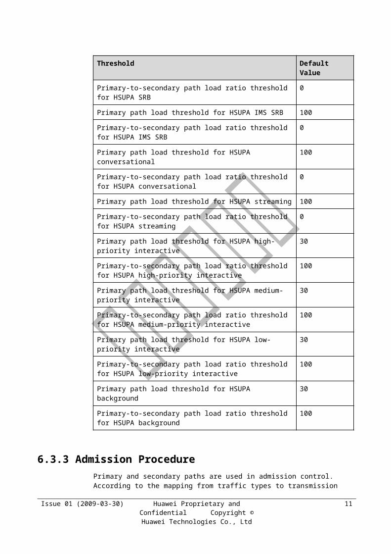
that is, the bandwidth is allocated by proportion based on the SPI weighting factors in the case that the GBR of the service is guaranteed. The differences are as follows:
The HSPA scheduling algorithm is applied to all the HSPA services except R99 services.
The Iub congestion control algorithm is applied only to the NRT services, including HSPA and R99 services. R99 services adopt the same service-to-SPI mapping mechanism as that of HSPA services, and SPI weighting factors are set for R99 services.
The HSPA scheduling algorithm is implemented in the NodeB. The downlink Iub congestion control algorithm is implemented in the RNC. The uplink Iub congestion control algorithm is implemented on the NodeB side.
The Iub congestion control algorithm must be implemented in the uplink and downlink directions. It consists of the following algorithms:
RLC (Radio Link Control) retransmission rate-based downlink congestion control algorithm
Backpressure-based downlink congestion control algorithm
NodeB HSDPA-based adaptive downlink flow control
R99 single service downlink congestion control algorithm
NodeB backpressure-based uplink congestion control algorithm
Transport layer uplink congestion control algorithm
R99 single service uplink congestion control algorithm
7.4 Downlink Iub Congestion Control Algorithm
7.4.1 Overview of the Downlink Iub Congestion Control Algorithm
The downlink congestion control algorithms are of four types, which are described in Table 7-1.
Table 7-1 Downlink congestion control algorithms
Congestion Control Algorithm
Scenario Service Type
RNC RLC retransmission rate-based congestion control algorithm
All networking scenarios R99 service, HSDPA service, RLC AM mode
NodeB HSDPA adaptive flow control algorithm
All networking scenarios HSDPA service
RNC backpressure-based downlink congestion control algorithm
Congestion and packet loss in the RNC. For packet loss at the transport layer, the shaping algorithm is also required.
R99 service, HSDPA NRT service
RNC R99 single service downlink congestion control algorithm
All networking scenarios R99 service
Issue 01 (2009-03-30) Huawei Proprietary and Confidential Copyright © Huawei Technologies Co.,
Ltd
3
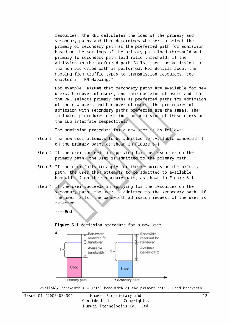
The recommended configurations for the downlink congestion control algorithms are as follows:
The RLC retransmission rate-based congestion control algorithm switch is disabled. Other algorithm switches are enabled.
In the convergence scenario, the multiple-level LPs are configured if the configuration of multiple-level LPs is supported.
In the IP transport scenario, the IP PM is enabled if it is supported.
The relations between the four downlink congestion control algorithms are as follows:
Relation between the RNC backpressure-based congestion control algorithm and the RNC RLC retransmission rate-based congestion control algorithm
− Both the algorithms are implemented in the RNC. Therefore, they may take effect simultaneously.
− When the backpressure-based congestion control algorithm switch of a service is enabled, the RLC retransmission rate-based congestion control algorithm switch is disabled automatically.
Relation between the RNC backpressure-based congestion control algorithm and the RNC R99 single service congestion control algorithm
− Both the algorithms are implemented in the RNC. Therefore, they may take effect simultaneously.
− In the case that backpressure takes effect, the backpressure-based congestion control algorithm ensures that no packet loss occurs in the RNC. The R99 single service congestion control algorithm monitors packet loss and reduces the rate only when congestion occurs on the transport network. Therefore, it has no impact on the backpressure-based congestion control algorithm. It serves as the supplement in the case that backpressure does not take effect.
Relation between the RNC R99 single service congestion control algorithm and the RNC RLC retransmission rate-based congestion control algorithm
− Both the algorithms are implemented in the RNC. Therefore, they may take effect simultaneously.
− The R99 single service congestion control algorithm can take the place of the RLC retransmission rate-based congestion control algorithm. Therefore, when the R99 single service congestion control algorithm takes effect, the RLC retransmission rate-based congestion control algorithm can be disabled.
Relation between the NodeB HSDPA flow control algorithm and the RNC backpressure-based congestion control algorithm
The HSDPA flow control algorithm is implemented in the NodeB, and the backpressure-based congestion control algorithm is implemented in the RNC. Therefore, they may take effect simultaneously.
− If the NodeB HSDPA flow control algorithm switch is set to NO_BW_SHAPING, then the two algorithms do not conflict in the case that backpressure takes effect. The congestion problem on the Iub interface cannot be solved in the case that backpressure does not take effect.
− If the NodeB HSDPA flow control algorithm switch is set to DYNAMIC_BW_SHAPING, then the two algorithms conflict in the case that backpressure takes effect. The NodeB HSDPA flow control algorithm can independently solve the congestion problem of HSDPA users on the Iub interface in the case that backpressure does not take effect.
Issue 01 (2009-03-30) Huawei Proprietary and Confidential Copyright © Huawei Technologies Co.,
Ltd
4

− If the NodeB HSDPA flow control algorithm switch is set to BW_SHAPING_ONOFF_TOGGLE, then the NodeB flow control policy is automatically set to DYNAMIC_BW_SHAPING and can independently solve the congestion problem of HSDPA users in the case that backpressure does not take effect. The NodeB flow control policy is automatically set to NO_BW_SHAPING in the case that backpressure takes effect.
Relation between the NodeB HSDPA flow control algorithm and the RNC RLC retransmission rate-based congestion control algorithm
− The NodeB HSDPA flow control algorithm is excellent. Therefore, the RLC retransmission rate-based congestion control algorithm of the HSDPA service is not used.
− When both the algorithms take effect simultaneously, one is applied to R99 services, and the other is applied to HSDPA services. They do not conflict with each other. Generally, the priority of R99 services is higher than that of HSDPA services. Therefore, the rate of HSDPA services is reduced till the rate reaches the minimum value. In this case, the RLC retransmission rate-based congestion control algorithm takes effect to limit the rate of R99 services.
Relation between the NodeB HSDPA flow control algorithm and the RNC R99 single service congestion control algorithm
− The HSDPA flow control algorithm is implemented in the NodeB, and the R99 single service congestion control algorithm is implemented in the RNC. Therefore, they may take effect simultaneously.
− When both the algorithms take effect simultaneously, one is applied to R99 services, and the other is applied to HSDPA services. They do not conflict. The R99 single service congestion control algorithm aids the NodeB HSDPA flow control algorithm in solving flow control problems of R99 services.
7.4.2 RNC RLC Retransmission Rate-Based Downlink Congestion Control Algorithm
The RNC RLC retransmission rate-based downlink congestion control algorithm is implemented in the RNC. It is applied to all the Iub interface boards. Based on the RLC retransmission rate, it solves the downlink congestion problems of R99 and HSDPA NRT services.
The prerequisites for implementing the algorithm are as follows:
For the R99 BE service, use the SET CORRMALGOSWITCH command, and set the DRA_R99_DL_FLOW_CONTROL_SWITCH subparameter of DraSwitch to On.
For the HSDPA BE service, use the SET CORRMALGOSWITCH command, and set the DRA_HSDPA_DL_FLOW_CONTROL_SWITCH subparameter of DraSwitch to On.
The algorithm is implemented as follows:
Step 1 The RNC initiates periodic monitoring of the RLC PDU retransmission rate. The monitoring period is specified by the MoniterPrd parameter. The RNC calculates the retransmission rate according to the following formula:
Fn = (1 – a) x Fm + a x Mn
Fn: retransmission rate to be calculated
Fm: previously calculated retransmission rate
n = m + 1
Issue 01 (2009-03-30) Huawei Proprietary and Confidential Copyright © Huawei Technologies Co.,
Ltd
5

Mn: currently measured retransmission rate
a = 0.5
Step 2 When the retransmission rate is higher than EventAThred in a specified continuous period (TimeToTriggerA x MoniterPrd ), event A is triggered.
For the R99 BE service, the RNC reduces the current transmission rate by 50%.
For the HSDPA BE service, the RNC reduces the current transmission rate by 50%.
After event A is triggered, there is a waiting period (PendingTimeA x MoniterPrd ). In this period, the RNC stops monitoring the retransmission rate.
Step 3 When the retransmission rate is lower than EventBThred in a specified continuous period (TimeToTriggerB x MoniterPrd ), event B is triggered.
For the R99 BE service, the RNC increases the current transmission rate by 130%.
For the HSDPA BE service, the RNC increases the current transmission rate by 130%.
After event B is triggered, there is a waiting period (PendingTimeB x MoniterPrd ). In this period, the RNC stops monitoring the retransmission rate.
The procedure for flow control algorithm 1 of the BE service is shown in Figure 7-1.
Figure 7-1 Procedure for flow control algorithm 1 of the BE service
Issue 01 (2009-03-30) Huawei Proprietary and Confidential Copyright © Huawei Technologies Co.,
Ltd
6
Through flow control algorithm 1, the transmission rate of the RNC matches the bandwidth on the Iub interface, as shown in Figure 7-2.
Figure 7-2 BE service flow control in the case of Iub congestion
----End
7.4.3 RNC Backpressure-Based Downlink Congestion Control Algorithm
The RNC backpressure-based downlink congestion control algorithm is implemented in the RNC. It is applied to downlink congestion of R99 and HSDPA NRT services.
The prerequisites for implementing the algorithm are as follows:
This algorithm is based on backpressure flow control of the interface board. The license must be obtained according to different network modes, and the Iub overbooking feature must be activated. The following functions require corresponding licenses:
− ATM Iub overbooking: used for the ATM non-hub network
− Hub Iub overbooking: used for the ATM hub network
− IP Iub overbooking: used for the IP network
The algorithm switch must be enabled.
The FLOWCTRLSWITCH parameter is set to ON, and the FCINDEX parameter together with the thresholds is used for port flow control. Therefore, the setting of FLOWCTRLSWITCH is based on the ports.
− For the ATM network, the ports are the UNI link, IMA group, fractional link, LP, and optical port.
− For the IP network, the ports are the LP, PPP link, MLPPP group, optical port, and Ethernet port.
The algorithm is implemented as follows:
Step 1 The interface boards monitor the transmission buffers of the queues on the Iub interface.
The ATM interface board has five queues, and the IP interface board has six queues.
For the IP interface board, the number of queues with absolute priorities can be set through the PQNUM parameter. The scheduling of queues with absolute priorities depends on the priorities of special users. The rest queues use the RR scheduling algorithm. The number of rest queues is equal to 6 minus the value of PQNUM. The RR scheduling is performed according to the sequence of the queues and then the sequence of the tasks.
Issue 01 (2009-03-30) Huawei Proprietary and Confidential Copyright © Huawei Technologies Co.,
Ltd
7
Step 2 When the buffer length of a queue is greater than the congestion threshold, the queue enters the congestion state. When a queue on the port is congested, the port becomes congested accordingly. The interface boards send congestion signals to the DPUb boards concerned. The DPUb boards reduce the transmission rate of the BE service to GBR x 10%.
The congestion thresholds are CONGTHD0, CONGTHD1, CONGTHD2, CONGTHD3, CONGTHD4, and CONGTHD5.
Step 3 When the buffer length of the queue is greater than the packet discarding threshold, the RNC starts discarding data packets from the buffer.
The packet discarding thresholds are DROPPKTTHD0, DROPPKTTHD1, DROPPKTTHD2, DROPPKTTHD3, DROPPKTTHD4, and DROPPKTTHD5.
The length of packets discarded from the queue is equal to the packet discarding threshold minus the congestion threshold.
Step 4 When the buffer length of the queue is smaller than the congestion recovery threshold, the queue leaves the congestion state. The port is recovered if all the queues on the port leave the congestion state. The interface boards send congestion resolving signals to the associated DPUb boards, and the DPUb boards restore the transmission rate of BE users on the port.
The recovery thresholds are CONGCLRTHD0, CONGCLRTHD1, CONGCLRTHD2, CONGCLRTHD3, CONGCLRTHD4, and CONGCLRTHD5.
The restored rate is r x 95%, where r is the final transmission rate of the user before the user enters the congestion state.
Step 5 After the BE users leave the congestion state, the RNC increases the transmission rate every 10 ms according to the increasing step until the BE users reach the Maximum Bit Rate (MBR). The value of MBR is carried on the Radio Access Bearer (RAB) from the Core Network (CN).
The initial increasing step of the transmission rate is 2,000 bit/s x SPI, and the step is doubled at intervals of 200 ms.
----End
The result of flow control algorithm 2 for the BE service is shown in Figure 7-1.
Issue 01 (2009-03-30) Huawei Proprietary and Confidential Copyright © Huawei Technologies Co.,
Ltd
8
Figure 7-1 Result of flow control algorithm 2 for the BE service
The other parameters used in flow control algorithm 2 are as follows:
TrafficClass
UserPriority
THP
SPI
BearType
7.4.4 RNC R99 Single Service Downlink Congestion Control Algorithm
The RNC R99 single service downlink congestion control algorithm is implemented in the RNC. The RNC extends the node synchronization frame to detect congestion in R99 service transport and thus controls the transmission rate of the downlink R99 service. The RNC adopts the policy of reducing rate by proportion and increasing rate by absolute rate to ensure fairness and to implement differentiated services. Therefore, the flow control problems of the R99 service can be solved.
The prerequisite for implementing the algorithm is that the DLR99CONGCTRLSWITCH parameter is set to ON.
The algorithm is implemented as follows:
Step 1 The RNC measures the number of FP packets in real time and sends the downlink node synchronization frame once a second to implement congestion detection based on the downlink node synchronization frame.
The downlink node synchronization frame contains the PM packet sequence number and the number of FP packets sent by the RNC (excluding the number of control frames).
Step 2 The NodeB measures the number of received FP packets in real time, fills the number of FP packets in the received downlink node synchronization frame, and then generates an uplink node synchronization frame and sends it to the RNC.
Issue 01 (2009-03-30) Huawei Proprietary and Confidential Copyright © Huawei Technologies Co.,
Ltd
9

Step 3 If the RNC detects frame loss and congestion of the downlink R99 service after receiving the uplink node synchronization frame and does not reduce the L2 transmission rate in a period of time, the RNC reduces the L2 transmission rate by a certain percentage to a rate not smaller than the GBR.
Step 4 The RNC increases the L2 transmission rate by a certain step every 1.5s to a rate not greater than the MBR.
The initial increasing step of the transmission rate is 2,000 bit/s x SPI, and the step is doubled at intervals of 20s.
Step 5 After obtaining the L2 transmission rate, the RNC sends data by using the leaky bucket algorithm.
----End
7.4.5 NodeB HSDPA Adaptive Flow Control AlgorithmThe NodeB HSDPA adaptive flow control algorithm is implemented in the NodeB. It is applied to the MAC-hs queues of the BE service and streaming service of HSDPA users.
The BE service is less sensitive to delay. The rate fluctuates considerably. When the data burst occurs, the rate may become very high.
The rate of the steaming service is relatively high, which may lead to congestion on the Iub interface.
The flow control policy is not used for the SRB, IMS, VoIP, or CS AMR service of HSDPA users because the amount of data is small and the services are sensitive to delay.
The flow control algorithm solves the Iub congestion problems of HSDPA users in various scenarios.
The prerequisites for implementing the algorithm are as follows:
The HSDPA MBR reporting switch is set as follows:
− When the switch is set to ON, the RNC sends the user MBR to the NodeB. When the NodeB MAC-hs flow control entity distributes flow to the users, the rate does not exceed the MBR.
− When the switch is set to OFF, the Iub MBR reporting function is disabled.
NOTE
This switch is not configurable. It is set to ON by default.
The NodeB Iub flow control algorithm switch Switch is set as follows:
− When the switch is set to DYNAMIC_BW_SHAPING, the NodeB adjusts the available bandwidth for HSDPA users based on the delay and packet loss condition on the Iub interface. Then, considering the rate on the air interface, the NodeB performs Iub shaping and distributes flow to HSDPA users.
− When the switch is set to NO_BW_SHAPING, the NodeB does not adjust the bandwidth based on the delay and packet loss condition on the Iub interface. The NodeB reports the conditions on the air interface to the RNC, and then the RNC performs bandwidth allocation.
− When the switch is set to BW_SHAPING_ONOFF_TOGGLE, the flow control policy for the ports of the NodeB is either DYNAMIC_BW_SHAPING or NO_BW_SHAPING in accordance with the congestion detection mechanism of the NodeB.
Issue 01 (2009-03-30) Huawei Proprietary and Confidential Copyright © Huawei Technologies Co.,
Ltd
10
This section describes the flow control policy used when Switch is set to BW_SHAPING_ONOFF_TOGGLE. The algorithm architecture is shown in Figure 7-1.
Figure 7-1 Dynamic flow control algorithm architecture
The algorithm is implemented as follows:
Step 1 The congestion status of the transport network is reported to the NodeB through the DRT and FSN. The NodeB monitors transmission delay and packet loss periodically. If the NodeB detects no congestion, it increases the HSDPA Iub bandwidth.
The Iub frame loss rate threshold is specified by DR. If the detected frame loss rate is lower than the threshold, no congestion due to packet loss occurs.
The Iub delay congestion threshold is specified by TD. If the detected delay is lower than the threshold, no congestion due to delay occurs.
If the NodeB detects no congestion in a period of time, it stops the delay detection and the algorithm switch is set to NO_BW_SHAPING. That is, flow shaping is disabled.
If the NodeB detects congestion due to packet loss, it continues with the delay detection and the algorithm switch is set to DYNAMIC_BW_SHAPING. That is, the Iub bandwidth adaptive algorithm and flow shaping are enabled.
Step 2 The NodeB adjusts the HSDPA Iub bandwidth based on the congestion due to delay and packet loss. The adjusted bandwidth is the input for the Iub shaping function of the NodeB.
Step 3 The NodeB allocates capacity to MAC-hs based on the rate on the Uu interface.
The allocated capacity does not exceed the MBR.
Step 4 Based on the capacity allocated on the Uu interface, the NodeB allocates the Iub bandwidth to HSDPA users and performs Iub shaping to ensure that the total flow of all the queues does not exceed the available Iub bandwidth. In this way, Iub interface congestion is controlled, Iub interface utilization is improved, and overload is prevented.
Issue 01 (2009-03-30) Huawei Proprietary and Confidential Copyright © Huawei Technologies Co.,
Ltd
11
If the Iub shaping function of the NodeB is disabled, skip this step.
Step 5 The RNC limits the bandwidth for each MAC-hs queue based on the HS-DSCH capacity allocation result.
----End
7.5 Uplink Iub Congestion Control Algorithm
7.5.1 Overview of the Uplink Iub Congestion Control Algorithm
The uplink congestion control algorithms are of four types, which are described in Table 7-1.
Table 7-1 Uplink congestion control algorithms
Congestion Control Algorithm
Scenario Service Type
NodeB backpressure-based uplink congestion control algorithm
The available bandwidth for LPs is known, and the NodeB boards support the algorithm.
R99 service and HSUPA service
NodeB uplink bandwidth adaptive adjustment algorithm
The bandwidth of various transport networks is unknown or the scenarios include ATM convergence, hub convergence, and slow changes in the bandwidth of transport networks.
R99 service and HSUPA service
RNC R99 single service uplink congestion control algorithm
All networking scenarios R99 service
NodeB cross-Iur single HSUPA service uplink congestion control algorithm
Iur congestion scenario HSUPA service
The recommended configurations for the uplink congestion control algorithms are as follows:
All the algorithm switches are enabled.
In the IP transport scenario, the IP PM is enabled if it is supported.
The relations between the four uplink congestion control algorithms are as follows:
The NodeB backpressure-based uplink congestion control algorithm and the NodeB uplink bandwidth adaptive adjustment algorithm are implemented in the NodeB. The RNC R99 single service uplink congestion control algorithm is implemented in the RNC. These three algorithms may take effect simultaneously.
The result (available bandwidth for LPs) of the NodeB uplink bandwidth adaptive adjustment algorithm is the input for the NodeB backpressure-based uplink congestion control algorithm. If the NodeB boards support the NodeB uplink bandwidth adaptive adjustment algorithm and the NodeB backpressure-based uplink congestion control algorithm, both the algorithms can be used together to solve the uplink Iub congestion
Issue 01 (2009-03-30) Huawei Proprietary and Confidential Copyright © Huawei Technologies Co.,
Ltd
12

problems (in direct connection and convergence scenarios). This is the main scheme of the uplink flow control algorithm.
If the NodeB supports the NodeB backpressure-based uplink congestion control algorithm and the NodeB uplink bandwidth adaptive adjustment algorithm, the RNC R99 single service uplink congestion control algorithm can control the transmission rate of UEs based on the backpressure flow control and rate limiting results. They do not conflict with each other. Otherwise, the RNC R99 single service uplink congestion control algorithm independently controls the transmission rate of UEs based on the FP congestion detection results.
If the NodeB supports the NodeB backpressure-based uplink congestion control algorithm and the NodeB uplink bandwidth adaptive adjustment algorithm, the NodeB cross-Iur single HSUPA service uplink congestion control algorithm can solve the packet loss problem due to Iur interface congestion for HSUPA users.
7.5.2 NodeB Backpressure-Based Uplink Congestion Control Algorithm (R99 and HSUPA)
The NodeB backpressure-based uplink congestion control algorithm is implemented in the NodeB to ensure that there is no congestion due to packet loss in the NodeB. The policy of reducing rate by proportion and increasing rate by absolute rate is adopted to ensure fairness between BE services.
NOTE
The switch of this algorithm is not configurable. It is set to ON by default.
Figure 7-1 shows the principle of the NodeB backpressure-based congestion control algorithm.
Figure 7-1 Principle of the NodeB backpressure-based uplink congestion control algorithm
The algorithm is implemented as follows:
Step 1 The interface boards monitor the transmission buffers of the LPs and queues on the Iub interface.
Issue 01 (2009-03-30) Huawei Proprietary and Confidential Copyright © Huawei Technologies Co.,
Ltd
13
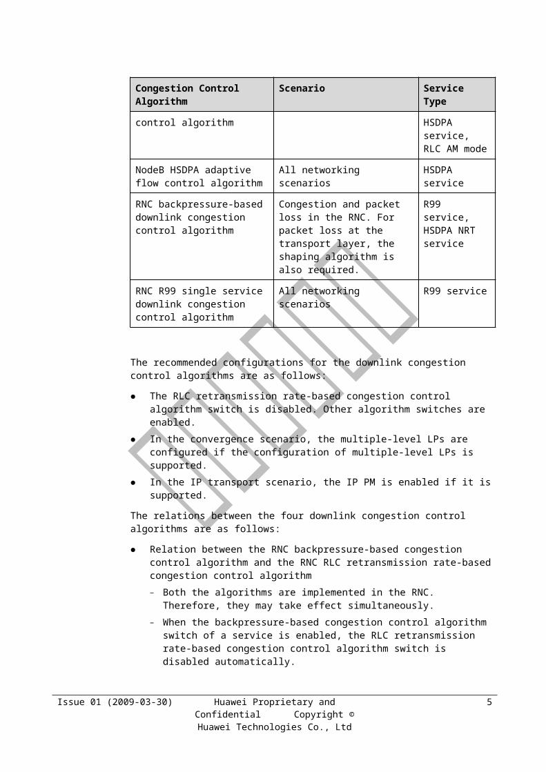
When congestion is detected, the interface boards send congestion signals to the DSP concerned. All the BE users on the DSP enter the congestion state. The transmission rate is limited but is not lower than the GBR.
For ATM transport or IP transport based on the V1 platform: The algorithm must calculate a virtual buffer data volume and check whether congestion occurs because LP shaping is not supported.
− If congestion is detected on the port, all queues are congested.
− If no congestion is detected on the port, the status of the queues must be checked on the basis of the buffer data of the queues.
For IP transport based on the V2 platform: The algorithm directly checks whether congestion occurs on the port based on the actually measured buffer usage on the port because LP shaping is supported. If congestion is detected on the port, the rates of all the BE users on the port are reduced.
Step 2 When the buffer data volume on the decoding DSP is larger than a certain threshold, some data packets in the buffer are discarded.
For HSUPA users, the data can be buffered in the decoding DSP for 500 ms and will be discarded after 500 ms.
For R99 users, the data can be buffered in the decoding DSP for 60 ms and will be discarded after 60 ms.
Step 3 When the buffer data volume of the LPs and queues is smaller than the congestion recovery threshold, congestion is resolved. The interface boards send the congestion resolving signals to the DSP concerned. The BE users on the port leave the congestion state, and the transmission rates are restored.
Step 4 After the BE users leave the congestion state, the decoding DSP increases the transmission rate by a certain step every 10 ms until the transmission rate of the BE users reaches the MBR.
The initial increasing step of the transmission rate is 2,000 bit/s x SPI, and the step is doubled at intervals of 200 ms.
Step 5 The buffer data volume on the decoding DSP is the input for scheduling. The hybrid service may consider the buffer conditions of several services on the decoding DSP.
----End
7.5.3 NodeB Uplink Bandwidth Adaptive Adjustment Algorithm
The NodeB uplink bandwidth adaptive adjustment algorithm is implemented in the NodeB. In the scenario of network convergence or hub NodeB, the bandwidth configured by the NodeB may be much greater than the available bandwidth on the transport network. The NodeB uplink bandwidth adaptive adjustment algorithm automatically monitors congestion on the transport network and adjusts the maximum available bandwidth on the Iub interface. Therefore, this algorithm is also called transport network congestion control algorithm.
The adjustment result is the input for the NodeB backpressure-based congestion control algorithm. Considering the difference between ATM transport and IP transport, two types of algorithms are available.
Issue 01 (2009-03-30) Huawei Proprietary and Confidential Copyright © Huawei Technologies Co.,
Ltd
14

NOTE
The switch of this algorithm is not configurable. It is set to ON by default.
Algorithm for ATM Transport
The RNC monitors congestion due to delay and frame loss based on the packet transmission time specified in the Spare Extension field in the FP frame and the number of FP packets sent by the NodeB. Then, the RNC returns the congestion indication according to the congestion detection result. The frame structure of the congestion indication is shown in Figure 7-1. At the same time, the cross-Iur indication is added to the congestion indication, which is used for the NodeB to perform cross-Iur flow control for HSUPA users.
Figure 7-1 Frame structure of the congestion indication on the transport network
Congestion Status indicates the congestion status of the transport network. Its values are as follows:
0: no TNL congestion
1: reserved for future use
2: TNL congestion detected by delay build-up
3: TNL congestion detected by frame loss
After receiving the non-cross-Iur congestion indication periodically measured on each LP, the NodeB adjusts the exit bandwidth on the NodeB side according to the following principles:
If the NodeB receives the congestion indication in which the value of Congestion Status is 2 or 3 in a measurement period, it reduces the exit bandwidth of the LP by a certain step.
Otherwise, the NodeB increases the exit bandwidth of the LP by a certain step, and the changed exit bandwidth does not exceed the configured bandwidth.
Algorithm for IP Transport
For IP transport, the NodeB directly obtains the congestion status of the transport network according to the IP PM result without using the congestion indication from the RNC.
After obtaining the Iub congestion status of the transport network, the NodeB adjusts the exit bandwidth according to the following principles:
If the NodeB detects congestion due to frame loss or delay in a measurement period, it reduces the exit bandwidth of the LP by a certain step.
Otherwise, the NodeB increases the exit bandwidth of the LP by a certain step, and the changed exit bandwidth does not exceed the configured bandwidth.
Issue 01 (2009-03-30) Huawei Proprietary and Confidential Copyright © Huawei Technologies Co.,
Ltd
15
7.5.4 RNC R99 Single Service Uplink Congestion Control Algorithm
The RNC R99 single service uplink congestion control algorithm monitors congestion by monitoring end-to-end packet loss (from the NodeB to the RNC) for each DCH FP at the FP layer. Then, the RNC controls the transmission rate of UEs through the RRC signaling TFC Control. This algorithm is applied to the R99 uplink congestion control scenario in which backpressure does not take effect.
NOTE
The switch of this algorithm is not configurable. It is set to ON by default.
The algorithm is implemented as follows:
Step 1 The uplink DCH data frame is extended to implement FP-based uplink congestion detection.
The extension information consists of the PM packet indication, PM packet transmission time, total number of FP packets sent by the decoding DSP (including data packets discarded from the buffer of the decoding DSP), and total number of FP packets sent by the decoding DSP to the transport network (excluding data packets discarded from the buffer of the decoding DSP).
Step 2 If the DCH FP frame carries the total number of FP packets sent by the NodeB, the RNC performs R99 single service uplink congestion detection.
If the FP of a service of a user detects the uplink R99 congestion due to frame loss,
− If the rate reducing period timer expires, the RNC reduces the rate of the uplink service by a level and notifies the UE through the TFC Control signaling. The rate is not lower than the GBR. Then, the rate reducing period timer and the congestion recovery timer are started.
− If the rate reducing period timer does not expire, the rate cannot be reduced, and the congestion recovery timer is restarted.
Step 3 If the congestion recovery timer expires and the current rate of the user does not reach the MBR, the RNC increases the rate by a level and notifies the UE through the TFC CONTROL signaling. Then, the congestion recovery timer is restarted.
----End
7.5.5 NodeB Cross-Iur Single HSUPA Service Uplink Congestion Control Algorithm
The NodeB cross-Iur single HSUPA service uplink congestion control algorithm is implemented in the NodeB. For users across the Iur interface, the NodeB adjusts the exit rate of a single service according to the TNL Congestion Indication returned by the SRNC to prevent congestion due to packet loss on the Iur interface.
The new boards of the RAN10.0 support this algorithm. The boards of the RAN10.0 or earlier versions do not support this algorithm.
NOTE
The switch of this algorithm is not configurable. It is set to ON by default.
Issue 01 (2009-03-30) Huawei Proprietary and Confidential Copyright © Huawei Technologies Co.,
Ltd
16
The algorithm is implemented as follows:
Step 1 For the cross-Iur HSUPA service, the RNC sends the cross-Iur TNL Congestion Indication to the NodeB and indicates that the user is across the Iur interface.
Step 2 After receiving the cross-Iur TNL Congestion Indication from the RNC, the NodeB performs the operation as follows:
The NodeB limits the transmission rate (not lower than the GBR) of the user and restarts the rate reducing and suspension period timer of the uplink cross-Iur HSUPA service if the TNL Congestion Indication indicates congestion due to frame loss or delay and the timer expires.
Step 3 In a period of 1s, the NodeB increases the transmission rate for the uplink cross-Iur HSUPA user by a level by a certain step until the rate of the BE user reaches the MBR.
The initial increasing step of the transmission rate is 2,000 bit/s x SPI, and the step is doubled at intervals of 20s.
Step 4 After obtaining the transmission rate, the decoding DSP sends data by using the leaky bucket algorithm.
If the NodeB supports uplink backpressure, the transmission rate is the minimum value between the rate limited by the backpressure algorithm and the rate specified by this algorithm.
----End
7.6 Iub Efficiency ImprovementThe Iub efficiency is improved in the following aspects:
IP RAN FP-MUX: The frame protocol multiplexing (FP-MUX) is used to encapsulate several small FP PDU frames (also called subframe) into a UDP packet, thus improving the transmission efficiency. The FP-MUX is only applied to Iub user plane data based on the UDP/IP protocol.
IP RAN header compression: IP RAN header compression is performed to compress the protocol header of the PPP frame to improve the bandwidth utilization.
FP silent mode: The FP silent mode is a mechanism of eliminating unused and null data on the Iub/Iur interface.
7.6.1 IP RAN FP-MUXThe FP-MUX is used to encapsulate several small FP PDU frames (also called subframe) into a UDP packet, thus improving the transmission efficiency.
The FP-MUX is applied only to Iub user plane data based on the UDP/IP protocol.
The FP-MUX can be applied to frames with the same priority, namely, frames with the same DSCP value.
Figure 7-1 shows the format of the FP-MUX UDP/IP packet.
Issue 01 (2009-03-30) Huawei Proprietary and Confidential Copyright © Huawei Technologies Co.,
Ltd
17
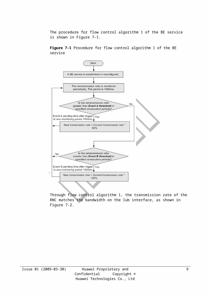
Figure 7-1 Format of the FP-MUX UDP/IP packet
To activate the FP-MUX, the FPMUXSWITCH parameter should be set to YES. SUBFRAMELEN indicates the maximum length of the subframe; MAXFRAMELEN indicates the maximum frame length of the FP-MUX UPD/IP packet. At the time set by FPTIME, the UDP packet is sent.
Only the FG2a and GOUa support the FP-MUX. Each board supports 1,800 FP-MUX streams. The QoS path occupies 14 FP-MUX streams for mapping, and the non-QoS path occupies only one FP-MUX stream.IP RAN Header Compression
IP RAN header compression is performed to compress the protocol header of the PPP frame to improve the bandwidth utilization. The RNC and NodeB support the following header compression methods.
ACFC
Address and Control Field Compression (ACFC) complies with RFC 1661. It is used to compress the address and control fields of the PPP protocol. Generally, the address and control field values are fixed values and need not be transferred each time. After the Link Control Protocol (LCP) negotiation of the PPP link is complete, the address and control field of successive packets can be compressed.
PFC
Protocol Field Compression (PFC) complies with RFC 1661. It is used to compress the 2-byte protocol field to a 1-byte one. The structure of this field is consistent with the ISO 3309 extension mechanism for the protocol field.
When the least significant bit of the protocol field is 0, the protocol field contains two bytes. The remaining bits follow this bit.
When the least significant bit of the protocol field is 1, the protocol field contains one byte. This byte is the last one.
Most packets can be compressed because the assigned protocol field value is generally less than 256.
Issue 01 (2009-03-30) Huawei Proprietary and Confidential Copyright © Huawei Technologies Co.,
Ltd
18
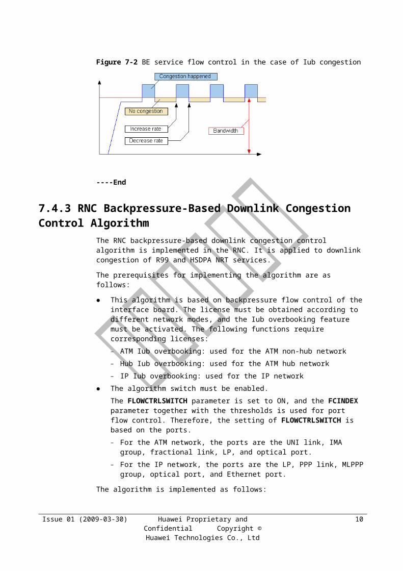
IPHC
IP Header Compression (IPHC) complies with RFC 2507 and RFC 3544. It is used to compress the IP/UDP header on the PPP link. IPHC improves the bandwidth utilization by using the following methods:
The unchanged header fields in the IP/UDP header are not carried in each packet.
The header fields changed in a specified mode are replaced by the less significant bits.
When a packet with a full header is occasionally sent, the header context can be established at both ends of the link. The original header can be restored according to the context and the received compressed header.
The associated parameter on the RNC side is IPHC.
The associated parameter on the NodeB side is IPHC.
7.6.2 FP Silent ModeThe FP silent mode saves the transmission bandwidth of the uplink R99 service and improves the uplink transmission efficiency.
Two modes, normal mode and silent mode, can be used in uplink transmission. When the transport bearer is established and the NodeB is informed through the related control plane procedure, the SRNC selects the transmission mode.
In normal mode, for the DCH, the NodeB continuously sends the UL DATA FRAME to the RNC.
In silent mode, when only one transport channel is transmitted on the transport bearer, the NodeB does not send the UL DATA FRAME to the RNC after receiving a TFI indicating TB numbered 0 in a TTI period.
In silent mode, for all associated DCHs, the NodeB does not send the UL DATA FRAME to the RNC after receiving a TFI indicating TB numbered 0.
In the current release, the transmission mode is permanently set to the normal mode.
7.7 IP PMOn the actual network, the bandwidth on the Iub interface may be variable. Based on the packet loss and delay on the IP transport network detected by IP PM, the transmission bandwidth on the Iub IP LP can be adjusted adaptively. The adjusted bandwidth can be used as the input for port backpressure.
The IP PM solution is described as follows:
If backpressure is implemented on the LP, congestion and packet loss do not occur on the LP but may occur on the transport network.
The RNC and NodeB implement IP PM in the following way to detect congestion and packet loss on the transport network:
− The transmitter sends a Forward Monitoring (FM) packet containing the count and timestamp of the transmit packet to the receiver.
− The receiver adds the count and timestamp of the receive packet to the FM packet to generate a Backward Reporting (BR) packet and then sends it to the transmitter.
Issue 01 (2009-03-30) Huawei Proprietary and Confidential Copyright © Huawei Technologies Co.,
Ltd
19

− The transmitter adjusts the available bandwidth on the LP according to the FM and BR packets and adjusts the rate on the LP according to the bandwidth adjustment result.
The dynamic adjustment of the bandwidth on the LP is dependent on the IP PM detection result. During the LP configuration, if the BWADJ parameter is set to ON, IP PM for all IP paths on the LP must be activated. Therefore, the system dynamically adjusts the bandwidth on the LP according to the Iub transmission quality information obtained by IP PM.
The predicted available bandwidth is also applied to the access algorithm. For details, see section 6.3 "Admission Control."
If the BWADJ parameter is set to ON, MAXBW and MINBW must be configured. If the BWADJ parameter is set to OFF, only one fixed bandwidth may be configured for the LP. Only the FG2a and GOUa support IP PM. Each board supports 500 PM streams. The QoS Path
needs to occupy a maximum of 14 PM streams. The non-QoS Path occupies only one PM stream. The ACT IPPM command is used to activate IP PM, and the DEA IPPM command is used to
deactivate IP PM.
Issue 01 (2009-03-30) Huawei Proprietary and Confidential Copyright © Huawei Technologies Co.,
Ltd
20
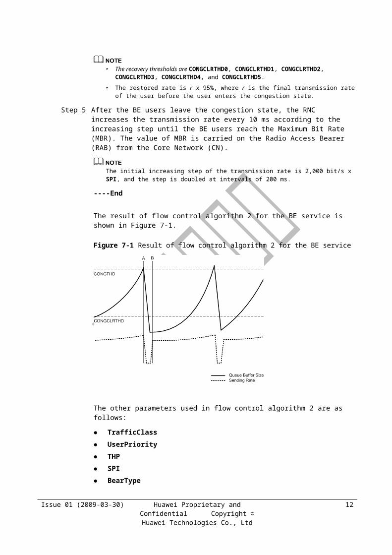
8 TRM Parameters
8.1 Description
Table 8-1 TRM parameter description
Parameter ID Description
Beartype This parameter specifies the bearer type of the service.- R99: The service is carried on a non-HSPA channel.- HSPA: The service is carried on an HSPA channel.
BWADJ Automatic bandwidth adjustment switch for logical ports.
BWDCONGBW If the available backward bandwidth is less than or equal to this value, the backward congestion alarm is emitted.
BWDCONGCLRBW If the available backward bandwidth is greater than this value, the backward congestion alarm is cleared.
BWDHORSVBW Reserved backward bandwidth for handover user.
CONGCLRTHD0 When the time of the queue 0 buffer no more than the value of this parameter, we cancel port flow control, and when the port flow control type is ATM, this parameter means the recover threshold of the CBR queue.
CONGCLRTHD1 When the time of the queue 1 buffer no more than the value of this parameter, we cancel port flow control, and when the port flow control type is ATM, this parameter means the recover threshold of the RTVBR queue.
CONGCLRTHD2 When the time of the queue 2 buffer no more than the value of this parameter, we cancel port flow control, and when the port flow control type is ATM, this parameter means the recover threshold of the NRTVBR queue.
CONGCLRTHD3 When the time of the queue 3 buffer no more than the value of this parameter, we cancel port flow control, and when the port flow control type is ATM, this parameter means the recover threshold of the UBR queue.
CONGCLRTHD4 When the time of the queue 4 buffer no more than the value of this parameter, we cancel port flow control, and when the port flow control type is ATM, this parameter means the recover threshold of the UBR+ queue.
CONGCLRTHD5 When the time of the queue 5 buffer no more than the value of this parameter, we cancel port flow control.
CONGTHD0 When the time of the queue 0 buffer no less than the value of this parameter, we begin port flow control, and when the port flow control type is ATM, this parameter
Issue 01 (2009-03-30) Huawei Proprietary and Confidential Copyright © Huawei Technologies Co.,
Ltd
1
Parameter ID Description
means the congestion threshold of the CBR queue.
CONGTHD1 When the time of the queue 1 buffer no less than the value of this parameter, we begin port flow control, and when the port flow control type is ATM, this parameter means the congestion threshold of the RTVBR queue.
CONGTHD2 When the time of the queue 2 buffer no less than the value of this parameter, we begin port flow control, and when the port flow control type is ATM, this parameter means the congestion threshold of the NRTVBR queue.
CONGTHD3 When the time of the queue 3 buffer no less than the value of this parameter, we begin port flow control, and when the port flow control type is ATM, this parameter means the congestion threshold of the UBR queue.
CONGTHD4 When the time of the queue 4 buffer no less than the value of this parameter, we begin port flow control, and when the port flow control type is ATM, this parameter means the congestion threshold of the UBR+ queue.
CONGTHD5 When the time of the queue 5 buffer no less than the value of this parameter, we begin port flow control.
DLR99CONGCTRLSWITCH
When the switch is selected, the congestion detection and control for DL R99 service is supported.
DR Discard Rate. The link is not congested when the frame loss ratio is lower than or equal to this threshold.
DraSwitch Dynamic resource allocation switch.1) DRA_AQM_SWITCH: When the switch is on, the active queue management algorithm is used for the RNC. 2) DRA_BE_EDCH_TTI_RECFG_SWITCH: When the switch is on, the TTI could be reconfigured to HSUPA traffic dynamically between 2ms and 10ms. 3) DRA_BE_RATE_DOWN_BF_HO_SWITCH: When the switch is on, the bandwidth for BE services is reduced before soft handover. It is recommended that the DCCC switch be on when this switch is on. 4) DRA_DCCC_SWITCH: When the switch is on, the dynamic channel reconfiguration control algorithm is used for the RNC. 5) DRA_HSDPA_DL_FLOW_CONTROL_SWITCH: When the switch is on, power control is enabled for HSDPA services in AM mode. 6) DRA_HSDPA_STATE_TRANS_SWITCH: When the switch is on, the status of the UE RRC that carrying HSDPA services can be changed to CELL_FACH at the RNC. If a PS BE service is carried over the HS-DSCH, the switch PS_BE_STATE_TRANS_SWITCH should be on simultaneously. If a PS real-time service is carried over the HS-DSCH, the switch PS_NON_BE_STATE_TRANS_SWITCH should be on simultaneously. 7) DRA_HSUPA_DCCC_SWITCH: When the switch is on, the DCCC algorithm is used for HSUPA. The DCCC switch must be also on before this switch takes effect. 8) DRA_HSUPA_STATE_TRANS_SWITCH: When the switch is on, the status of the UE RRC that carrying HSUPA services can be changed to CELL_FACH at the RNC. If a PS BE service is carried over the E-DCH, the switch PS_BE_STATE_TRANS_SWITCH should be on simultaneously. If a PS real-time service is carried over the E-DCH, the switch PS_NON_BE_STATE_TRANS_SWITCH should be on simultaneously. 9) DRA_IU_QOS_RENEG_SWITCH: When the switch is on and the Iu QoS RENEQ license is activated, the RNC supports renegotiation of the maximum rate if
Issue 01 (2009-03-30) Huawei Proprietary and Confidential Copyright © Huawei Technologies Co.,
Ltd
2
Parameter ID Description
the QoS of real-time services is not ensured according to the cell status. 10) DRA_PS_BE_STATE_TRANS_SWITCH: When the switch is on, UE RRC status transition (CELL_FACH/CELL_PCH/URA_PCH) is allowed at the RNC. 11) DRA_PS_NON_BE_STATE_TRANS_SWITCH: When the switch is on, the status of the UE RRC that carrying real-time services can be changed to CELL_FACH at the RNC. 12) DRA_R99_DL_FLOW_CONTROL_SWITCH: Under a poor radio environment, the QoS of high speed services drops considerably and the TX power is overly high. In this case, the RNC can set restrictions on certain transmission formats based on the transmission quality, thus lowering traffic speed and TX power. When the switch is on, the Iub overbooking function is enabled. 13) DRA_THROUGHPUT_DCCC_SWITCH: When the switch is on, the DCCC based on traffic statistics is supported over the DCH.
DROPPKTTHD0 When the time of the queue 0 buffer no less than the value of this parameter, we begin to loss the packets, and when the port flow control type is ATM, this parameter means the packet discard threshold of the CBR queue.
DROPPKTTHD1 When the time of the queue 1 buffer no less than the value of this parameter, we begin to loss the packets, and when the port flow control type is ATM, this parameter means the packet discard threshold of the RTVBR queue.
DROPPKTTHD2 When the time of the queue 2 buffer no less than the value of this parameter, we begin to loss the packets, and when the port flow control type is ATM, this parameter means the packet discard threshold of the NRTVBR queue.
DROPPKTTHD3 When the time of the queue 3 buffer no less than the value of this parameter, we begin to loss the packets, and when the port flow control type is ATM, this parameter means the packet discard threshold of the UBR queue.
DROPPKTTHD4 When the time of the queue 4 buffer no less than the value of this parameter, we begin to loss the packets, and when the port flow control type is ATM, this parameter means the packet discard threshold of the UBR+ queue .
DROPPKTTHD5 When the time of the queue 5 buffer no less than the value of this parameter, we begin to loss the packets.
DSCP This parameter specifies the DiffServ Code Point for the ping command.
EventAThred This parameter specifies the threshold of event A, that is, the upper limit of RLC retransmission ratio.
EventBThred This parameter specifies the threshold of event B, that is, the lower limit of RLC retransmission ratio.
FCINDEX Flow control parameter index.
FLOWCTRLSWITCH
Flow control switch.
FPMUXSWITCH Indicating whether to check the link of the IP path with FPMUX. Only FG2a and GOUa board support FPMUX.
FTI Index of the factor table used by the current adjacent node.
FWDCONGBW If the available forward bandwidth is less than or equal to this value, the forward
Issue 01 (2009-03-30) Huawei Proprietary and Confidential Copyright © Huawei Technologies Co.,
Ltd
3
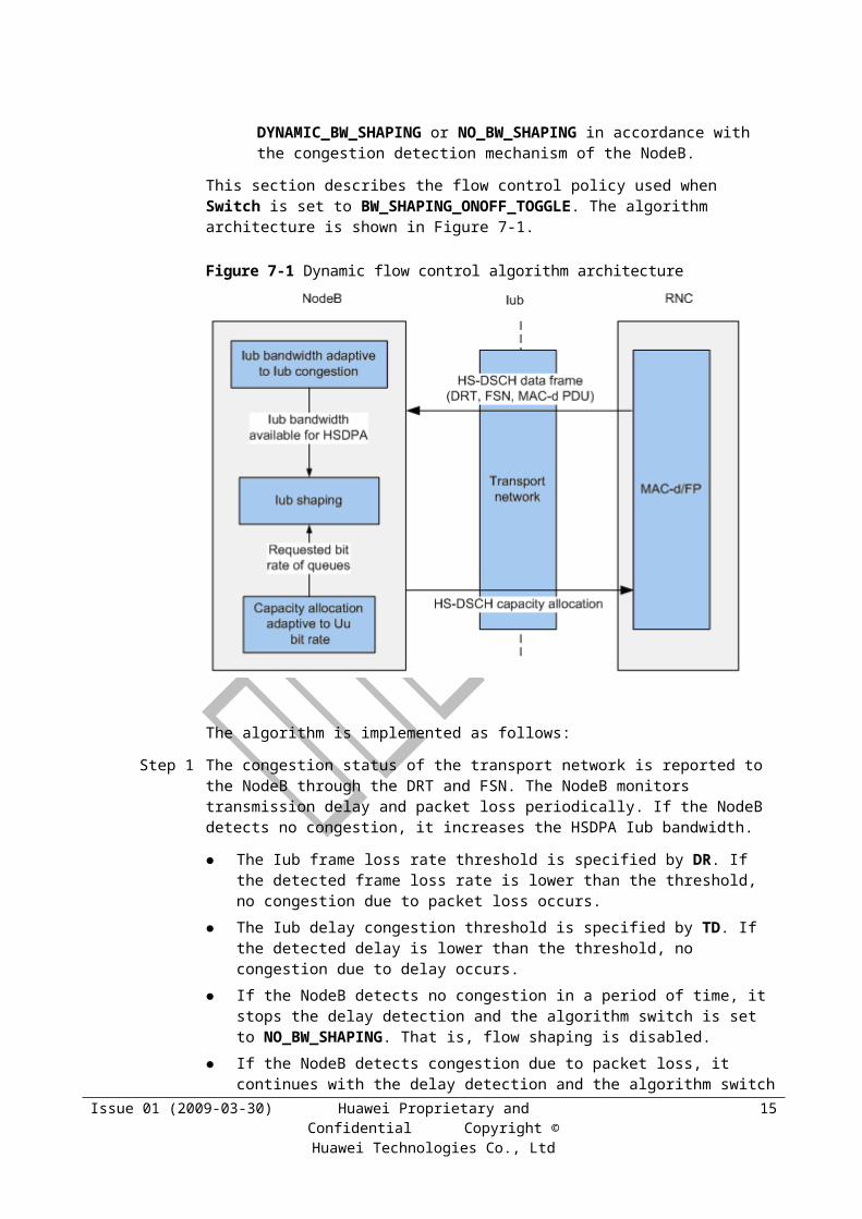
Parameter ID Description
congestion alarm is emitted.
FWDCONGCLRBW If the available forward bandwidth is greater than this value, the forward congestion alarm is cleared.
FWDHORSVBW Reserved forward bandwidth for handover user.
IPHC IP header compress function of the PPP link.
IPHC IP Header Compress. DISABLE means that the IP header is not expected to be compressed from the peer end. ENABLE means that the UDP/IP header is expected to be compressed from the peer end.
MAXBW Maximum bandwidth of automatic adjustment for logical ports.
MAXFRAMELEN Maximum Frame Length.
MINBW Minimum bandwidth of automatic adjustment for logical ports.
MoniterPrd This parameter specifies a sampling period of retransmission ratio monitoring after the RLC entity is established or reconfigured.
NodeBLdcAlgoSwitch
IUB_LDR (Iub congestion control algorithm): When the NodeB Iub load is heavy, users are assembled in priority order among all the NodeBs and some users are selected for LDR action (such as BE service rate reduction) in order to reduce the NodeB Iub load.NODEB_CREDIT_LDR (NodeB level credit congestion control algorithm): When the NodeB level credit load is heavy, users are assembled in priority order among all the NodeBs and some users are selected for LDR action in order to reduce the NodeB level credit load.LCG_CREDIT_LDR (Cell group level credit congestion control algorithm): When the cell group level credit load is heavy, users are assembled in priority order among all the NodeBs and some users are selected for LDR action in order to reduce the cell group level credit load. IUB_OLC (Iub Overload congestion control algorithm): When the NodeB Iub load is Overload, users are assembled in priority order among all the NodeBs and some users are selected for Olc action in order to reduce the NodeB Iub load.To enable some of the algorithms above, select them. Otherwise, they are disabled.
PendingTimeA This parameter specifies the number of pending periods after event A is triggered. During the pending time, no event related to retransmission ratio is reported.
PendingTimeB This parameter specifies the number of pending periods after event B is triggered. During the pending time, no event related to retransmission ratio is reported.
PQNUM This parameter is valid only when the port flow control type is IP; Priority queue number of ATM is fixed to 2 and can not be modified.
PT Port Type
RXTRFX Receive traffic record index of the SAAL link.
SPI This parameter indicates the scheduling priority. The value 15 indicates the highest priority and the value 0 indicates the lowest.
SUBFRAMELEN Max subframe length.
Switch Flow Control Switch
Issue 01 (2009-03-30) Huawei Proprietary and Confidential Copyright © Huawei Technologies Co.,
Ltd
4
Parameter ID Description
TD Time Delay. The link is not congested when the delay is lower than this threshold.
TimeToMoniter This parameter specifies the delay time after the RLC entity is established or reconfigured and before the retransmission ratio monitoring is started.
TimeToTriggerA This parameter specifies the number of consecutive periods during which the percentage of retransmitted PDUs is higher than the threshold of event A before event A is triggered.Recommended value (default value): 2.
TimeToTriggerB This parameter specifies the number of consecutive periods during which the percentage of retransmitted PDUs is lower than the threshold of event B before event B is triggered.
TrafficClass This parameter specifies the traffic class that the service belongs to. Based on Quality of Service (QoS), there are two traffic classes: interactive, background.
TXTRFX TX traffic record index at the port from which the IPoA PVC goes out of the RNC. The TX traffic must have been configured.
UserPriority This parameter specifies the user priority. The user classes in descending order of priority are Gold, Silver, and then Copper.
Beartype This parameter specifies the bearer type of the service.- R99: The service is carried on a non-HSPA channel.- HSPA: The service is carried on an HSPA channel.
BWADJ Automatic bandwidth adjustment switch for logical ports.
BWDCONGBW If the available backward bandwidth is less than or equal to this value, the backward congestion alarm is emitted.
BWDCONGCLRBW If the available backward bandwidth is greater than this value, the backward congestion alarm is cleared.
BWDHORSVBW Reserved backward bandwidth for handover user.
CONGCLRTHD0 When the time of the queue 0 buffer no more than the value of this parameter, we cancel port flow control, and when the port flow control type is ATM, this parameter means the recover threshold of the CBR queue.
CONGCLRTHD1 When the time of the queue 1 buffer no more than the value of this parameter, we cancel port flow control, and when the port flow control type is ATM, this parameter means the recover threshold of the RTVBR queue.
CONGCLRTHD2 When the time of the queue 2 buffer no more than the value of this parameter, we cancel port flow control, and when the port flow control type is ATM, this parameter means the recover threshold of the NRTVBR queue.
CONGCLRTHD3 When the time of the queue 3 buffer no more than the value of this parameter, we cancel port flow control, and when the port flow control type is ATM, this parameter means the recover threshold of the UBR queue.
CONGCLRTHD4 When the time of the queue 4 buffer no more than the value of this parameter, we cancel port flow control, and when the port flow control type is ATM, this parameter
Issue 01 (2009-03-30) Huawei Proprietary and Confidential Copyright © Huawei Technologies Co.,
Ltd
5

Parameter ID Description
means the recover threshold of the UBR+ queue.
CONGCLRTHD5 When the time of the queue 5 buffer no more than the value of this parameter, we cancel port flow control.
CONGTHD0 When the time of the queue 0 buffer no less than the value of this parameter, we begin port flow control, and when the port flow control type is ATM, this parameter means the congestion threshold of the CBR queue.
CONGTHD1 When the time of the queue 1 buffer no less than the value of this parameter, we begin port flow control, and when the port flow control type is ATM, this parameter means the congestion threshold of the RTVBR queue.
CONGTHD2 When the time of the queue 2 buffer no less than the value of this parameter, we begin port flow control, and when the port flow control type is ATM, this parameter means the congestion threshold of the NRTVBR queue.
CONGTHD3 When the time of the queue 3 buffer no less than the value of this parameter, we begin port flow control, and when the port flow control type is ATM, this parameter means the congestion threshold of the UBR queue.
CONGTHD4 When the time of the queue 4 buffer no less than the value of this parameter, we begin port flow control, and when the port flow control type is ATM, this parameter means the congestion threshold of the UBR+ queue.
8.2 Values and Ranges
Table 8-1 TRM parameter values and parameter ranges
Parameter ID
Default Value
GUI Value Range
Actual Value Range
Unit MML Command NE
Beartype - R99, HSPA R99, HSPA None SET USERGBR(Mandatory)
RNC
BWADJ OFF OFF, ON OFF, ON None ADD IPLOGICPORT(Optional)
RNC
BWDCONGBW
0 0~320000 0~320000 kbit/s ADD AAL2PATH(Optional)
RNC
BWDCONGCLRBW
0 0~320000 0~320000 kbit/s ADD AAL2PATH(Optional)
RNC
BWDHORSVBW
0 0~320000 0~320000 kbit/s ADD AAL2PATH(Optional)
RNC
CONGCLRTHD0
15 10~150 10 to 150 ms ADD PORTFLOWCTRLPARA(Optional)
RNC
Issue 01 (2009-03-30) Huawei Proprietary and Confidential Copyright © Huawei Technologies Co.,
Ltd
6
Parameter ID
Default Value
GUI Value Range
Actual Value Range
Unit MML Command NE
CONGCLRTHD1
15 10~150 10 to 150 ms ADD PORTFLOWCTRLPARA(Optional)
RNC
CONGCLRTHD2
15 10~150 10 to 150 ms ADD PORTFLOWCTRLPARA(Optional)
RNC
CONGCLRTHD3
15 10~150 10 to 150 ms ADD PORTFLOWCTRLPARA(Optional)
RNC
CONGCLRTHD4
25 10~150 10 to 150 ms ADD PORTFLOWCTRLPARA(Optional)
RNC
CONGCLRTHD5
25 10~150 10 to 150 ms ADD PORTFLOWCTRLPARA(Optional)
RNC
CONGTHD0 25 10~150 10 to 150 ms ADD PORTFLOWCTRLPARA(Optional)
RNC
CONGTHD1 25 10~150 10 to 150 ms ADD PORTFLOWCTRLPARA(Optional)
RNC
CONGTHD2 25 10~150 10 to 150 ms ADD PORTFLOWCTRLPARA(Optional)
RNC
CONGTHD3 25 10~150 10 to 150 ms ADD PORTFLOWCTRLPARA(Optional)
RNC
CONGTHD4 50 10~150 10 to 150 ms ADD PORTFLOWCTRLPARA(Optional)
RNC
CONGTHD5 50 10~150 10 to 150 ms ADD PORTFLOWCTRLPARA(Optional)
RNC
DLR99CONGCTRLSWITCH
- OFF(The switch of DL R99 congestion control is off), ON(The switch of DL R99 congestion control is on)
OFF, ON None SET DPUCFGDATA(Optional)
RNC
DR 1 0~1000 0~1, Step: None SET Node
Issue 01 (2009-03-30) Huawei Proprietary and Confidential Copyright © Huawei Technologies Co.,
Ltd
7
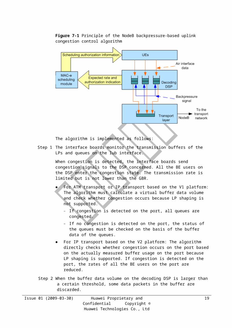
Parameter ID
Default Value
GUI Value Range
Actual Value Range
Unit MML Command NE
0.001 HSDPAFLOWCTRLPARA(Optional)
B
DraSwitch - DRA_AQM_SWITCH, DRA_BE_EDCH_TTI_RECFG_SWITCH, DRA_BE_RATE_DOWN_BF_HO_SWITCH, DRA_DCCC_SWITCH, DRA_HSDPA_DL_FLOW_CONTROL_SWITCH, DRA_HSDPA_STATE_TRANS_SWITCH, DRA_HSUPA_DCCC_SWITCH, DRA_HSUPA_STATE_TRANS_SWITCH, DRA_IU_QOS_RENEG_SWITCH, DRA_PS_BE_STATE_TRANS_SWITCH, DRA_PS_NON_BE_STATE_TRANS_SWITCH, DRA_R99_DL_FLOW_CONTROL_SWITCH, DRA_THROUGHPUT_DCCC_SWITCH
DRA_AQM_SWITCH, DRA_BE_EDCH_TTI_RECFG_SWITCH, DRA_BE_RATE_DOWN_BF_HO_SWITCH, DRA_DCCC_SWITCH, DRA_HSDPA_DL_FLOW_CONTROL_SWITCH, DRA_HSDPA_STATE_TRANS_SWITCH, DRA_HSUPA_DCCC_SWITCH, DRA_HSUPA_STATE_TRANS_SWITCH, DRA_IU_QOS_RENEG_SWITCH, DRA_PS_BE_STATE_TRANS_SWITCH, DRA_PS_NON_BE_STATE_TRANS_SWITCH, DRA_R99_DL_FLOW_CONTROL_SWITCH, DRA_THROUGHPUT_DCCC_SWITCH
None SET CORRMALGOSWITCH(Optional)
RNC
DROPPKTTHD0
60 10~150 10 to 150 ms ADD PORTFLOWCTRLPARA(Optional)
RNC
DROPPKTTHD1
60 10~150 10 to 150 ms ADD PORTFLOWCTRLPARA(Optional)
RNC
Issue 01 (2009-03-30) Huawei Proprietary and Confidential Copyright © Huawei Technologies Co.,
Ltd
8

Parameter ID
Default Value
GUI Value Range
Actual Value Range
Unit MML Command NE
DROPPKTTHD2
60 10~150 10 to 150 ms ADD PORTFLOWCTRLPARA(Optional)
RNC
DROPPKTTHD3
60 10~150 10 to 150 ms ADD PORTFLOWCTRLPARA(Optional)
RNC
DROPPKTTHD4
80 10~150 10 to 150 ms ADD PORTFLOWCTRLPARA(Optional)
RNC
DROPPKTTHD5
80 10~150 10 to 150 ms ADD PORTFLOWCTRLPARA(Optional)
RNC
DSCP 0(PING IP)-(SET PHBMAP,SET DSCPMAP)62(ADD SCTPLNK)
0~63 0 to 63 None PING IP(Optional)SET DSCPMAP(Mandatory)ADD SCTPLNK(Optional)SET PHBMAP(Mandatory)
RNC
EventAThred 160 0~1000 0~100, step: 0.1 per cent
ADD TYPRABRLC(Optional)
RNC
EventBThred 80 0~1000 0~100, step: 0.1 per cent
ADD TYPRABRLC(Optional)
RNC
FCINDEX 1(ADD ATMLOGICPORT, ADD UNILNK, ADD IMAGRP, ADD FRALNK)-(ADD PORTFLOWCTRLPARA, SET ETHPORT,SET OPT)0(ADD IPLOGICPORT, ADD PPPLNK, ADD
0~1999 0 to 1999 None ADD FRALNK(Optional)ADD IMAGRP(Optional)SET OPT(Mandatory)SET ETHPORT(Mandatory)ADD MPGRP(Optional)ADD PPPLNK(Optional)ADD UNILNK(Optional)ADD ATMLOGICPORT(Optional)ADD PORTFLOWCTRLPARA(Mandatory)ADD
RNC
Issue 01 (2009-03-30) Huawei Proprietary and Confidential Copyright © Huawei Technologies Co.,
Ltd
9
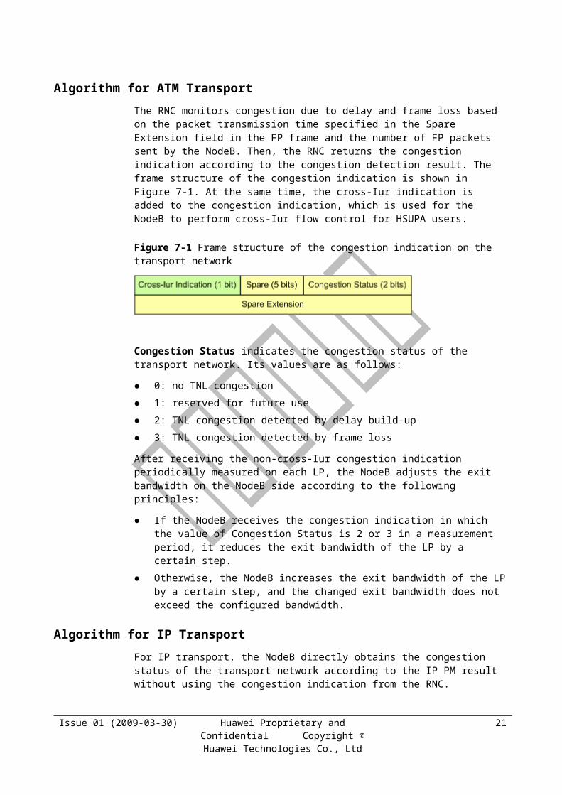
Parameter ID
Default Value
GUI Value Range
Actual Value Range
Unit MML Command NE
MPGRP) IPLOGICPORT(Optional)
FLOWCTRLSWITCH
ON(ADD ATMLOGICPORT, ADD UNILNK, ADD MPGRP, ADD IPLOGICPORT, ADD IMAGRP, ADD PPPLNK, ADD FRALNK)-(SET ETHPORT,SET OPT)
OFF, ON OFF, ON None ADD FRALNK(Optional)SET OPT(Optional)ADD PPPLNK(Optional)ADD IMAGRP(Optional)ADD IPLOGICPORT(Optional)ADD MPGRP(Optional)ADD UNILNK(Optional)ADD ATMLOGICPORT(Optional)SET ETHPORT(Optional)
RNC
FPMUXSWITCH
NO NO, YES NO, YES None ADD IPPATH(Optional)
RNC
FTI - 0~33 0~33 None ADD ADJMAP(Mandatory)
RNC
FWDCONGBW
0 0~320000 0~320000 kbit/s ADD AAL2PATH(Optional)
RNC
FWDCONGCLRBW
0 0~320000 0~320000 kbit/s ADD AAL2PATH(Optional)
RNC
FWDHORSVBW
0 0~320000 0~320000 kbit/s ADD AAL2PATH(Optional)
RNC
IPHC UDP/IP_HC
No_HC, UDP/IP_HC
No_HC(Disable head compress),UDP/IP_HC(Use UDP/IP head compress)
None ADD PPPLNK(Optional)
RNC
IPHC ENABLE DISABLE(The IP header is not expected to be compressed from the peer), ENABLE(The UDP/IP header is expected to
DISABLE, ENABLE
None ADD MPGRP(Optional)ADD PPPLNK(Optional)
NodeB
Issue 01 (2009-03-30) Huawei Proprietary and Confidential Copyright © Huawei Technologies Co.,
Ltd
10
Parameter ID
Default Value
GUI Value Range
Actual Value Range
Unit MML Command NE
be compressed from the peer)
MAXBW - 1~1000 64~64000 step:64
kbit/s ADD IPLOGICPORT(Mandatory)
RNC
MAXFRAMELEN
270 24~1031 24~1031 byte ADD IPPATH(Optional)
RNC
MINBW - 1~1000 64~64000 step:64
kbit/s ADD IPLOGICPORT(Mandatory)
RNC
MoniterPrd 1000 40~60000 40~60000 ms ADD TYPRABRLC(Optional)
RNC
NodeBLdcAlgoSwitch
- IUB_LDR, NODEB_CREDIT_LDR, LCG_CREDIT_LDR, IUB_OLC
IUB_LDR, NODEB_CREDIT_LDR, LCG_CREDIT_LDR, IUB_OLC
None ADD NODEBALGOPARA(Optional)
RNC
PendingTimeA
1 0~1000 0~1000 None ADD TYPRABRLC(Optional)
RNC
PendingTimeB
1 0~1000 0~1000 None ADD TYPRABRLC(Optional)
RNC
PQNUM - 0~5 0 to 5 None ADD PORTFLOWCTRLPARA(Mandatory)
RNC
PT - BOOL(Boolean port), VALUE(Analog port)
BOOL(Boolean port), VALUE(Analog port)
None SET ALMPORT NodeB
RXTRFX - 100~1999 100~1999 None ADD SAALLNK(Mandatory) ADD AAL2PATH(Mandatory) ADD VPCLCX(Mandatory) ADD IPOAPVC(Optional)
RNC
SPI - 0~15 0~15 None SET SPIFACTOR(Mandator
RNC
Issue 01 (2009-03-30) Huawei Proprietary and Confidential Copyright © Huawei Technologies Co.,
Ltd
11

Parameter ID
Default Value
GUI Value Range
Actual Value Range
Unit MML Command NE
y) SET SCHEDULEPRIOMAP(Mandatory)
SUBFRAMELEN
127 16~1023 16~1023 byte ADD IPPATH(Optional)
RNC
Switch BW_SHAPING_ONOFF_TOGGLE
DYNAMIC_BW_SHAPING: According to the flow control of STATIC_BW_SHAPING, traffic is allocated to HSDPA users when the delay and packet loss on the Iub interface are taken into account. The RNC use the R6 switch to perform this function. It is recommended that the RNC in compliance with R6 should perform this function.
NO_BW_SHAPING: The NodeB does not allocate bandwidth according to the configuration or delay on the Iub interface. The RNC allocates the bandwidth according to the bandwidth on the Uu interface reported by the NodeB. To perform this
STATIC_BW_SHAPING, DYNAMIC_BW_SHAPING, NO_BW_SHAPING, BW_SHAPING_ONOFF_TOGGLE
None SET HSDPAFLOWCTRLPARA(Optional)
NodeB
Issue 01 (2009-03-30) Huawei Proprietary and Confidential Copyright © Huawei Technologies Co.,
Ltd
12
Parameter ID
Default Value
GUI Value Range
Actual Value Range
Unit MML Command NE
function, the reverse flow control switch must be enabled by the RNC. The link is not congested when the delay is lower than this threshold. The link is not congested when frame loss ratio is no higher than this threshold.
BW_SHAPING_ONOFF_TOGGLE: If BW_SHAPING_ONOFF_TOGGLE is selected, the system automatically selects DYNAMIC_BW_SHAPING or NO_BW_SHAPING on the basis of the NodeB congestion detection mechanism. In other words, DYNAMIC_BW_SHAPING is selected when congestion is detected; NO_BW_SHAPING is selected when there is no congestion within a specific time. BW_SHAPING
Issue 01 (2009-03-30) Huawei Proprietary and Confidential Copyright © Huawei Technologies Co.,
Ltd
13
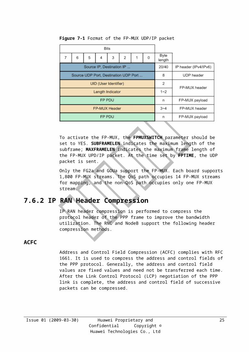
Parameter ID
Default Value
GUI Value Range
Actual Value Range
Unit MML Command NE
_ONOFF_TOGGLE, DYNAMIC_BW_SHAPING, and NO_BW_SHAPING are flow control strategies applied at the NodeB port.
TD 4 0~100 0~500, Step: 5ms
ms SET HSDPAFLOWCTRLPARA(Optional)
NodeB
TimeToMoniter
5000 0~500000 0~500000 ms ADD TYPRABRLC(Optional)
RNC
TimeToTriggerA
2 1~100 1~100 None ADD TYPRABRLC(Optional)
RNC
TimeToTriggerB
14 1~100 1~100 None ADD TYPRABRLC(Optional)
RNC
TrafficClass - INTERACTIVE, BACKGROUND
INTERACTIVE, BACKGROUND
None SET SCHEDULEPRIOMAP(Mandatory)SET USERGBR(Mandatory)SET FACHBANDWIDTH(Mandatory)SET USERHAPPYBR(Mandatory)SET DTXDRXPARA(Mandatory)SET HSSCCHLESSOPPARA(Mandatory)
RNC
TXTRFX - 100~1999 100 to 1999 None ADD IPOAPVC(Optional)ADD AAL2PATH(Mandatory)ADD SAALLNK(Mandatory)
RNC
Issue 01 (2009-03-30) Huawei Proprietary and Confidential Copyright © Huawei Technologies Co.,
Ltd
14
Parameter ID
Default Value
GUI Value Range
Actual Value Range
Unit MML Command NE
ADD VPCLCX(Mandatory)
UserPriority - GOLD, SILVER, COPPER
GOLD, SILVER, COPPER
None SET SCHEDULEPRIOMAP(Mandatory)SET USERGBR(Mandatory)SET FACHBANDWIDTH(Mandatory)SET USERHAPPYBR(Mandatory)
RNC
The Default Value column is valid for only the optional parameters.
The "-" symbol indicates no default value.
Issue 01 (2009-03-30) Huawei Proprietary and Confidential Copyright © Huawei Technologies Co.,
Ltd
15
9 TRM Reference Documents
The following lists the reference documents related to the feature:
1. ITU-T Recommendation I.361 “B-ISDN ATM Layer Specification”
2. ITU-T Recommendation I.363.2 “ATM Adaptation layer specification: Type 2 AAL”
3. ITU-T Recommendation I.366.1 “Segmentation and Reassembly Service Specific Convergence Sublayer for the AAL type 2”
4. AF-TM-0121.000 “Traffic Management 4.1”
5. AF-PHY-0086.001 “Inverse Multiplexing for ATM (IMA) Specification Version 1.1”
6. RFC1661 “The Point-to-Point Protocol (PPP), provides a standard method for transporting multi-protocol datagrams over point-to-point links”
7. RFC1662 "PPP in HDLC-link Framing"
8. RFC1990 "The PPP Multilink Protocol (ML-PPP)"
9. RFC2686 "The Multi-Class Extension to Multi-link PPP (MC-PPP)"
10. RFC3153 "PPP Multiplexing (PPPmux)"
11. RFC894 "Standard for the Transmission of IP Datagrams over Ethernet Networks"
12. RFC1042 "A Standard for the Transmission of IP Datagrams over IEEE 802 Networks"
13. 3GPP TS 25.423 "UTRAN Iur interface RNSAP signaling"
14. 3GPP TS 25.426 "UTRAN Iur and Iub Interface Data Transport"
15. 3GPP TS 25.427 "UTRAN Iur and Iub Interface User Plane Protocols for DCH Data Streams"
16. 3GPP TS 25.212 "Multiplexing and Channel Coding"
17. 3GPP TS 25.221 "Physical Channels and Mapping of Transport Channels onto Physical Channels"
18. Basic Feature Description of Huawei UMTS RAN11.0 V1.5
19. Optional Feature Description of Huawei UMTS RAN11.0 V1.5
Issue 01 (2009-03-30) Huawei Proprietary and Confidential Copyright © Huawei Technologies Co.,
Ltd
1
10 Appendix
10.1 Default TRMMAP Table for the ATM-Based Iub and Iur Interfaces
Table 10-1 Default TRMMAP table for the ATM-based Iub and Iur interfaces
TC/THP Gold Silver Copper
Primary Secondary
Primary Secondary
Primary Secondary
Common channel RT_VBR None – – – –
SRB RT_VBR None – – – –
SIP RT_VBR None – – – –
AMR RT_VBR None RT_VBR None RT_VBR None
R99 CS conversational RT_VBR None RT_VBR None RT_VBR None
R99 CS streaming RT_VBR None RT_VBR None RT_VBR None
R99 PS conversational RT_VBR None RT_VBR None RT_VBR None
R99 PS streaming RT_VBR None RT_VBR None RT_VBR None
R99 PS high-priority interactive
NRT_VBR
None NRT_VBR
None NRT_VBR
None
R99 PS medium-priority interactive
NRT_VBR
None NRT_VBR
None NRT_VBR
None
R99 PS low-priority interactive
NRT_VBR
None NRT_VBR
None NRT_VBR
None
R99 PS background NRT_VBR
None NRT_VBR
None NRT_VBR
None
HSDPA SRB RT_VBR None RT_VBR None RT_VBR None
HSDPA SIP RT_VBR None RT_VBR None RT_VBR None
HSDPA voice RT_VBR None RT_VBR None RT_VBR None
HSDPA conversational RT_VBR None RT_VBR None RT_VBR None
Issue 01 (2009-03-30) Huawei Proprietary and Confidential Copyright © Huawei Technologies Co.,
Ltd
1
TC/THP Gold Silver Copper
Primary Secondary
Primary Secondary
Primary Secondary
HSDPA streaming RT_VBR None RT_VBR None RT_VBR None
HSDPA high-priority interactive
UBR None UBR None UBR None
HSDPA medium-priority interactive
UBR None UBR None UBR None
HSDPA low-priority interactive
UBR None UBR None UBR None
HSDPA background UBR None UBR None UBR None
HSUPA SRB RT_VBR None RT_VBR None RT_VBR None
HSUPA SIP RT_VBR None RT_VBR None RT_VBR None
HSUPA voice RT_VBR None RT_VBR None RT_VBR None
HSUPA conversational RT_VBR None RT_VBR None RT_VBR None
HSUPA streaming RT_VBR None RT_VBR None RT_VBR None
HSUPA high-priority interactive
UBR None UBR None UBR None
HSUPA medium-priority interactive
UBR None UBR None UBR None
HSUPA low-priority interactive
UBR None UBR None UBR None
HSUPA background UBR None UBR None UBR None
10.2 Default TRMMAP Table for the IP-Based Iub and Iur Interfaces
Table 10-1 Default TRMMAP table for the IP-based Iub and Iur interfaces
TC/THP Gold Silver Copper
Primary Secondary
Primary
Secondary
Primary
Secondary
Common channel EF None – – – –
SRB EF None – – – –
SIP EF None – – – –
Issue 01 (2009-03-30) Huawei Proprietary and Confidential Copyright © Huawei Technologies Co.,
Ltd
2
TC/THP Gold Silver Copper
Primary Secondary
Primary
Secondary
Primary
Secondary
AMR EF None EF None EF None
R99 CS conversational AF43 None AF43 None AF43 None
R99 CS streaming AF33 None AF33 None AF33 None
R99 PS conversational AF43 None AF43 None AF43 None
R99 PS streaming AF33 None AF33 None AF33 None
R99 PS high-priority interactive
AF33 None AF33 None AF33 None
R99 PS medium-priority interactive
AF33 None AF33 None AF33 None
R99 PS low-priority interactive
AF33 None AF33 None AF33 None
R99 PS background AF13 None AF13 None AF13 None
HSDPA SRB EF None – – – –
HSDPA SIP EF None – – – –
HSDPA voice AF43 None AF43 None AF43 None
HSDPA conversational AF43 None AF43 None AF43 None
HSDPA streaming AF33 None AF33 None AF33 None
HSDPA high-priority interactive
AF11 None AF11 None AF11 None
HSDPA medium-priority interactive
AF11 None AF11 None AF11 None
HSDPA low-priority interactive
AF11 None AF11 None AF11 None
HSDPA background BE None BE None BE None
HSUPA SRB EF None – – – –
HSUPA SIP EF None – – – –
HSUPA voice AF43 None AF43 None AF43 None
HSUPA conversational AF43 None AF43 None AF43 None
HSUPA streaming AF33 None AF33 None AF33 None
HSUPA high-priority interactive
AF23 None AF23 None AF23 None
Issue 01 (2009-03-30) Huawei Proprietary and Confidential Copyright © Huawei Technologies Co.,
Ltd
3
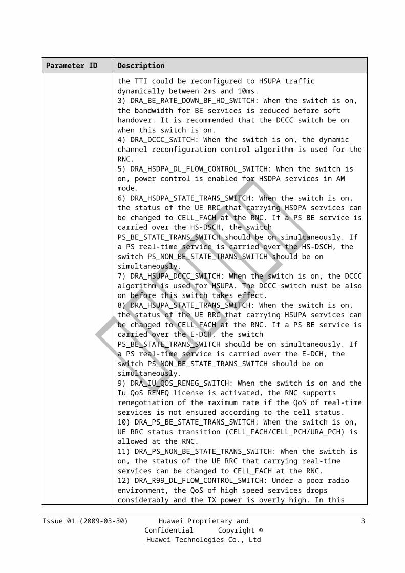
TC/THP Gold Silver Copper
Primary Secondary
Primary
Secondary
Primary
Secondary
HSUPA medium-priority interactive
AF23 None AF23 None AF23 None
HSUPA low-priority interactive
AF23 None AF23 None AF23 None
HSUPA background AF13 None AF13 None AF13 None
10.3 Default TRMMAP Table for the ATM&IP-Based Iub Interface
Table 10-1 Default TRMMAP table for the ATM&IP-based Iub interface
TC/THP Gold Silver Copper
Primary Secondary
Primary Secondary
Primary Secondary
Common channel RT_VBR EF – – – –
SRB RT_VBR EF – – – –
SIP RT_VBR EF – – – –
AMR RT_VBR EF RT_VBR EF RT_VBR EF
R99 CS conversational
RT_VBR AF43 RT_VBR AF43 RT_VBR AF43
R99 CS streaming RT_VBR AF33 RT_VBR AF33 RT_VBR AF33
R99 PS conversational
RT_VBR AF43 RT_VBR AF43 RT_VBR AF43
R99 PS streaming RT_VBR AF33 RT_VBR AF33 RT_VBR AF33
R99 PS high-priority interactive
NRT_VBR AF33 NRT_VBR AF33 NRT_VBR AF33
R99 PS medium-priority interactive
NRT_VBR AF33 NRT_VBR AF33 NRT_VBR AF33
R99 PS low-priority interactive
NRT_VBR AF33 NRT_VBR AF33 NRT_VBR AF33
R99 PS background NRT_VBR AF13 NRT_VBR AF13 NRT_VBR AF13
HSDPA SRB EF RTVBR – – – –
HSDPA SIP EF RTVBR – – – –
Issue 01 (2009-03-30) Huawei Proprietary and Confidential Copyright © Huawei Technologies Co.,
Ltd
4
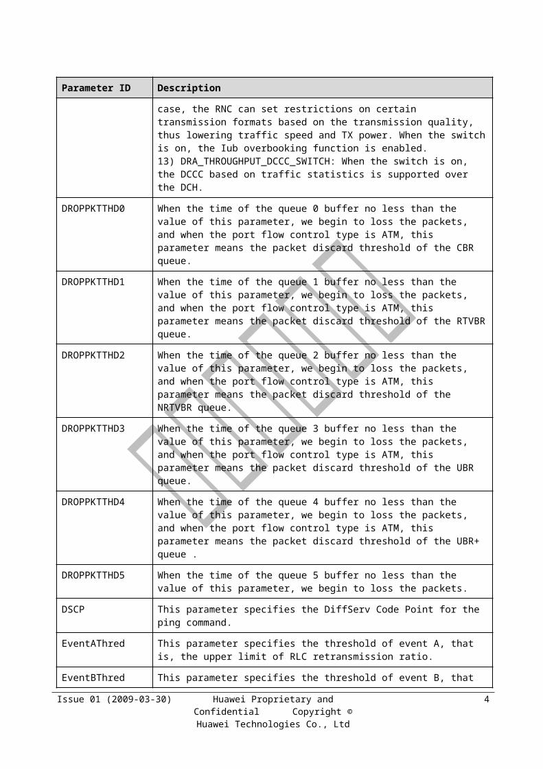
TC/THP Gold Silver Copper
Primary Secondary
Primary Secondary
Primary Secondary
HSDPA voice RT_VBR AF43 RT_VBR AF43 RT_VBR AF43
HSDPA conversational
RT_VBR AF43 RT_VBR AF43 RT_VBR AF43
HSDPA streaming RT_VBR AF33 RT_VBR AF33 RT_VBR AF33
HSDPA high-priority interactive
AF23 UBR AF23 UBR AF23 UBR
HSDPA medium-priority interactive
AF23 UBR AF23 UBR AF23 AF11
HSDPA low-priority interactive
AF23 UBR AF23 UBR AF23 AF11
HSDPA background AF13 UBR AF13 UBR AF13 UBR
HSUPA SRB EF RTVBR – – – –
HSUPA SIP EF RTVBR – – – –
HSUPA voice RT_VBR AF43 RT_VBR AF43 RT_VBR AF43
HSUPA conversational
RT_VBR AF43 RT_VBR AF43 RT_VBR AF43
HSUPA streaming RT_VBR AF33 RT_VBR AF33 RT_VBR AF33
HSUPA high-priority interactive
AF23 UBR AF23 UBR AF23 UBR
HSUPA medium-priority interactive
AF23 UBR AF23 UBR AF23 AF11
HSUPA low-priority interactive
AF23 UBR AF23 UBR AF23 AF11
HSUPA background AF13 UBR AF13 UBR AF13 UBR
Issue 01 (2009-03-30) Huawei Proprietary and Confidential Copyright © Huawei Technologies Co.,
Ltd
5
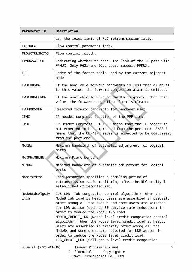
10.4 Default TRMMAP Table for the Hybrid-IP-Based Iub Interface
Table 10-1 Default TRMMAP table for the hybrid-IP-based Iub interface
TC/THP Gold Silver Copper
Primary
Secondary
Primary
Secondary
Primary Secondary
Common channel EF LQEF – – – –
SRB EF LQEF – – – –
SIP EF LQEF – – – –
AMR EF LQEF EF LQEF EF LQEF
R99 CS conversational AF43 LQAF43 AF43 LQAF43 AF43 LQAF43
R99 CS streaming AF33 LQAF33 AF33 LQAF33 AF33 LQAF33
R99 PS conversational AF43 LQAF43 AF43 LQAF43 AF43 LQAF43
R99 PS streaming AF43 LQAF43 AF43 LQAF43 AF43 LQAF43
R99 PS high-priority interactive
AF33 LQAF33 AF33 LQAF33 AF33 LQAF33
R99 PS medium-priority interactive
AF33 LQAF33 AF33 LQAF33 AF33 LQAF33
R99 PS low-priority interactive
AF33 LQAF33 AF33 LQAF33 AF33 LQAF33
R99 PS background AF13 LQAF13 AF13 LQAF13 AF13 LQAF13
HSDPA SRB EF LQEF – – – –
HSDPA SIP EF LQEF – – – –
HSDPA voice AF33 LQAF33 AF33 LQAF33 AF33 LQAF33
HSDPA conversational AF33 LQAF33 AF33 LQAF33 AF33 LQAF33
HSDPA streaming AF33 LQAF33 AF33 LQAF33 AF33 LQAF33
HSDPA high-priority interactive
AF23 LQAF23 AF23 LQAF23 AF23 LQAF23
HSDPA medium-priority interactive
AF23 LQAF23 AF23 LQAF23 AF23 LQAF23
HSDPA low-priority interactive
AF23 LQAF23 AF23 LQAF23 AF23 LQAF23
HSDPA background AF13 LQAF13 AF13 LQAF13 AF13 LQAF13
HSUPA SRB EF LQEF – – – –
Issue 01 (2009-03-30) Huawei Proprietary and Confidential Copyright © Huawei Technologies Co.,
Ltd
6
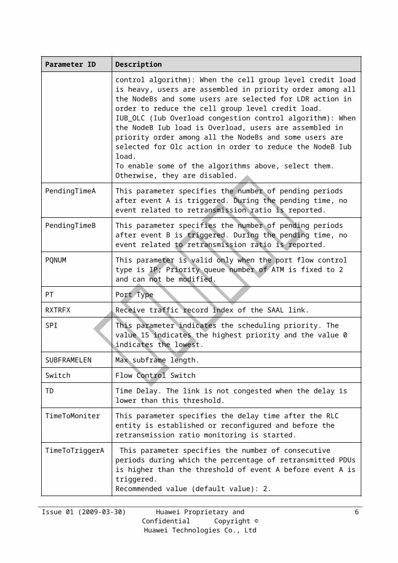
TC/THP Gold Silver Copper
Primary
Secondary
Primary
Secondary
Primary Secondary
HSUPA SIP EF LQEF – – – –
HSUPA voice AF33 LQAF33 AF33 LQAF33 AF33 LQAF33
HSUPA conversational AF33 LQAF33 AF33 LQAF33 AF33 LQAF33
HSUPA streaming AF33 LQAF33 AF33 LQAF33 AF33 LQAF33
HSUPA high-priority interactive
AF23 LQAF23 AF23 LQAF23 AF23 LQAF23
HSUPA medium-priority interactive
AF23 LQAF23 AF23 LQAF23 AF23 LQAF23
HSUPA low-priority interactive
AF23 LQAF23 AF23 LQAF23 AF23 LQAF23
HSUPA background AF13 LQAF13 AF13 LQAF13 AF13 LQAF13
10.5 Default TRMMAP Table for the ATM-Based Iu-CS Interface
Table 10-1 Default TRMMAP table for the ATM-based Iu-CS interface
TC/THP Gold Silver Copper
Primary Secondary
Primary Secondary
Primary Secondary
AMR RT_VBR None RT_VBR None RT_VBR None
CS conversational RT_VBR None RT_VBR None RT_VBR None
CS streaming RT_VBR None RT_VBR None RT_VBR None
Issue 01 (2009-03-30) Huawei Proprietary and Confidential Copyright © Huawei Technologies Co.,
Ltd
7

10.6 Default TRMMAP Table for the IP-Based Iu-CS Interface
Table 10-1 Default TRMMAP table for the IP-based Iu-CS interface
TC/THP Gold Silver Copper
Primary Secondary
Primary Secondary
Primary Secondary
AMR EF None EF None EF None
CS conversational AF43 None AF43 None AF43 None
CS streaming AF33 None AF33 None AF33 None
10.7 Default TRMMAP Table for the Iu-PS Interface
Table 10-1 Default TRMMAP table for the Iu-PS interface
TC/THP Gold Silver Copper
Primary
Secondary
Primary Secondary
Primary
Secondary
SIP EF None – – – –
PS conversational AF43 None AF43 None AF43 None
PS streaming AF43 None AF43 None AF43 None
PS high-priority interactive
AF33 None AF33 None AF33 None
PS medium-priority interactive
AF33 None AF33 None AF33 None
PS low-priority interactive
AF33 None AF33 None AF33 None
PS background AF13 None AF13 None AF13 None
Issue 01 (2009-03-30) Huawei Proprietary and Confidential Copyright © Huawei Technologies Co.,
Ltd
8