transmission unavailability of frequency diversity …bryanfields.net/mw-papers/bstj oct 1979...
TRANSCRIPT
~
.) [ )
j
,f
Co yright © 1979 American Telephone and Telegraph Company p THE BELL SYSTEM TECHNICAL JOURNAL
Vol. 58. No.8, October 1979 Printed in U.S.A.
Transmission Unavailability of FrequencyDiversity Protected Microwave FM Radio
Systems Caused by Multipath Fading
By A. VIGANTS and M. V. PURSLEY
(Manuscript received April 2. 1979)
Estimates of transmission unavailability caused by multipath fading are needed to determine the adequacy of diversity protection arrangements. A computer program producing such estimates was made available for general Bell System use in 1977. In this paper, we summarize the underlying mathematical model of frequency diversity operation and atmospheric multipath fading and use it to study frequency diversity behavior.
I. INTRODUCTION
Microwave FM radio systems utilized in the Bell System provide protected broadband communications channels that generally have a
. capacity, depending on the frequency band and on the type of equipment, of 1200 to 2400 message circuits per channel. The protected channels, with protection provided by radio switching systems, are referred to as "working" channels, to distinguish these from the actual radio channels, which are assigned as either "regular" or "protection" channels. The number of regular channels in a radio system equals the number of working channels. Equipment failures, atmospheric fading, or other impairments in a regular channel cause temporary transfers of the communications traffic to a protection channel at a different radio frequency, if an unoccupied and unimpaired protection channel is available. In the case of fading, such frequency-diversity protection switching capitalizes on the frequency selectivity of the multipath fading process, where, at an instant in time, the strength ofthe received signal is a function of frequency. The Bell System long-haul microwave FM radio network contains approximately 1600 one-way frequencydiversity switching sections (800 route segments) with an average of three radio hops per switching section.
1779
:..--
The communications traffic in a working channel can be temporarily ,11
subjected to high noise when, in a switching section, the number of impaired radio channels exceeds the number of protection channels. Bell System practice is to describe this in terms of the amount of time during which the noise in a working channel exceeds 55 dBrncO in a message circuit at the top frequency assignment in the baseband.! In this paper, this time is referred to as "service failure time" in accordance with designations on protection switching equipment and terminology used in the operation of the plant. The terms "service failure" and "outage" are frequently synonymous,l but use of the latter term can sometimes result in semantic difficulties, since some service failures may not result in outages as perceived or defined by some communications users.
In modern microwave radio systems, protection requirements are frequently governed by the presence of multipath fading,2-13 as opposed to causes associated with equipment or human intervention. l Estimates of service failure time due to multipath fading are therefore needed to determine the adequacy of diversity protection arrangements when new routes are planned, when transmission parameters of existing routes are changed, or when alternate protection strategies are considered for future use. In 1977, a computer program producing such estimates was made available for general Bell System application. It is extensively used to treat everyday design and planning tasks on an individualized basis for microwave FM radio routes equipped with frequency-diversity and space-diversity9 protection.
A mathematical model of frequency-diversity operation and multipath fading is central to the computer program. In this paper, the model is summarized and utilized to study representative radio systems on fully and partially developed routes. The effect of radio channels with reduced fade margins, the service failure time of individual channels, and parameters that can be used to characterize frequencydiversity systems are treated. A discussion is included of the addition of space-diversity protection to frequency-diversity protection, often necessary to reduce service failure time.
The numerical results presented in this paper should be considered in the context of transmission performance objectives. A proposed design or modification of a frequency-diversity protection switching section containing S radio hops is satisfactory when
s 2: Th :::; Tohj , (1) h-l
where Th is the estimated service failure time of an average radio channel due to multipath fading on a particular radio hop. The service failure time due to simultaneous deep fading on different hops is much
1780 THE BELL SYSTEM TECHNICAL JOURNAL, OCTOBER 1979
smaller and is therefore neglected in the above expression. The designobjective time Tobj is obtained from the reliability objectives for microwave FM radio, which specify an annual outage of 0.02 percent or less due to all causes for a two-way circuit on a 4000-mile long-haul or a 250-mile short-haul route. l In practice, this objective is prorated to the actual distance and applied to the service failure time. One-half the objective is allocated to multipath fading, and the other half to equipment, maintenance, a~d other causes.9 For multipath fading, onehalf the O.Ol-percent two-way allocation is applied to each direction of transmission. This accommodates customers that may transmit in only one direction and conforms to the structure of the plant, where independent protection switchi):"lg systems and different radioJrequencies are used in the two directions of transmission. Furthermore, the service failure time associated with a single protection switching system can be expected to be substantially larger than the service failure time occurring simultaneously in the two directions, since the latter kind of failure requires simultaneous deep fading on a larger number of radio channels. Consequently, the one-way multipath-fading service failure time objective for a section of a route containing S hops is, in seconds per year,
S
Tobj = (1600/D ref) L Dh , (2) h=!
where Dref is 4000 miles for long-haul and 250 miles for short-haul radio, and D h is the hop length in miles. In the case of a frequencydiversity switching section containing a single 25-mile hop, the values of Tobj are 10 seconds per year for long-haul and 160 seconds per year for short-haul radio. In the past, it was often assumed that only half the hops on a long route would experience significant fading. I.
9 This assumption is no longer necessary, since fading estimates can now be made for every hop on a route.5.9
II. THE MATHEMATICAL MODEL
The service failure time of an average working channel, caused by multipath fading on a particular radio hop, can be expressed as
Th = N-1Zh , (3)
Where N is the number of working channels and Zh, referred to as the facility service failure time, is the sum of the service failure times of the working channels. The facility service failure time can be expressed as
N
Zh = L iT" (i), (4) ;=1
TRANSMISSION UNAVAILABILITY 1781
where Ttl (i) is the accumulated time during which exactly i of the N working channels experience service failure. The terms in this sum are associated ~th simultaneous fading of radio channels. For a frequencydiversity protection switching section with M radio channels of which u are protection channels,
M= u+ N, (5)
eq. (4) becomes N
Zh = 2: iT'(u + i), (6) i=l
where T' (u + i) is the accumulated time during which exactly u + i of the M radio channels have failed simultaneously. A failure in this context is an exceedance of the 55-dBrncO noise value.
The simultaneous fading of radio channels is normally described in terms of the amount of time during which particular sets of u· + i channels have failed, with the status of the other M - u - i channels not specified. With such a time denoted by Tk(u + i), the expression for Zh becomes an alternating series
N J(II+i)
Zh = 2: 2: (-If-1C~~\-2 Tk(u + i), (7) i-I h-l
where J(u + i) is the binomial coefficient C;%." and where the subscript k enumerates the sets of u + i channels obtainable from the M channels. This expression has been used by other authors, I but its general mathematical equivalence to the definition in eq. (6) has not been demonstrated; a proof of this equivalence is supplied in Appendix A.
The expressions for the simultaneous failure time of a number of radio channels, denoted by Th(u + i), are based on a genenilized model of simultaneous multipath fading in an arbitrary number of radio channels obtained empirically from experimental data. The estimation ·f
of the amount of fading and the calculation of Th(u + i) are summarized in Appendix B. A simplified form of Tk(u + i), without path length
.~~ dependence and without accommodation of fade margin differences between radiQ"channels, has been utilized previously to demonstrate the feasibility of joint frequency-diversity protection for radio systems in the 4-GHz and 6-GHz bands. I
Numerical evaluation of Zh from the alternating series requires a computer program that efficiently selects and classifies radio channel combinations from a particular frequency plan and calculates the corresponding values of Th(u + i), since the number of terms can be large. For example, there are 184,756 ten-channel combinations when
(I'all radio channels in the 4-GHz and 6-GHz bands are used (400A
1782 THE BELL SYSTEM TECHNICAL JOURNAL, OCTOBER 1979
protection system with 2· protection and 18 regular channels). The computation of the combinations is discussed in Appendix C.
III. REPRESENTATIVE RESULTS FOR FULLY DEVELOPED ROUTES
A fully developed 4-GHz route contains a total of 12 radio channels consisting of one protection channel and 11 regular channels. The notation 1 X 11 is used to describe this. On fully developed 6-GHz routes, the total number of radio channels is 8 and the protection scheme is 1 X 7. When both bands are utilized, the two protection channels can be placed in the 6-GHz band, which results in 2 X 18 protection.
Representative estimated values of service failure times for these protection schemes can be obtained from calculations for a switching section containing one 25-mile hop with average terrain and climate. Without diversity protection, the service failure time of an average channel in the 4-GHz band is 269 seconds per year for a fade margin of 37 dB. In the 6-GHz band, the corresponding service failure time is 208 seconds per year for a fade margin of 40 dB.
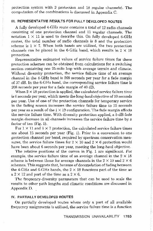
When 2 X 18 protection is applied, the calculated service failure time is 6 seconds per year, which meets the long-haul objective of 10 seconds per year. Use of one of the protection channels for temporary service in the fading season increases the service failure time to 15 seconds per year as a result of the 1 X 19 configuration. The fade margin affects the service failure time. With diversity protection applied, a 5-dB fade margin decrease in all channels increases the service failure time by a factor of ten (Fig. 1).
For 1 X 11 and 1 X 7 protection, the calculated service failure times are about 15 seconds per year (Fig. 1). Prior to a conversion to one protection channel per band, required by spectrum conservation measures, the service failure times for 2 X 10 and 2 X 6 protection would have been about 6 seconds per year, meeting the long-haul objective.
The relative positions of the curves in Fig. 1 are significant. For example, the service failure time of an average channel in the 2 X 18 scheme is between those for average channels in the 2 X 10 and 2 X 6 schemes. This suggests that, because of decorrelation offading between the 4-GHz and 6-GHz bands, the 2 X 18 functions part of the time as a 2 X 12 and part of the time as a 2 X 6.
The frequency-diversity parameters that can be used to scale the results to other path lengths and climatic conditions are discussed in Appendix D.
IV. PARTIALLY DEVELOPED ROUTES
On partially developed routes where only a part of all available frequency assignments is utilized, the service failure time is a function
TRANSMISSION UNAVAILABILITY 1783
0:: « w >0:: w "(/)
o z o o w (/)
*w ~
I-w 10 0:: ::> --' « u.. w o > 0:: w (/)
w
« '" 0:: w > «
-4 -2 0 2 4 6
DEVIATION FROM FADE MARGIN, ALL CHANNELS, IN DECIBELS
Fig, I-Service failure ti~e of average working channel due to multipath fading on a 25-mile hop with average climate and terrain. Fade margin = 37 dB, 4-GHz band; fade margin = 40 dB, 6-GHz band; average annual temperature = 55°F; terrain roughness = 50 ft.
• Average service failure time and service failure time of average working channel are synonymous in the context of this work.
of the frequency arrangement of the radio channels. A "best-case" arrangement is one where the frequency separation of adjacent channels is maximized. In a "worst-case" arrangement, the channels are crowded into the high end of the frequency band. Such arrangements do not necessarily correspond to actual or permitted growth strategies, but they do provide bounds for the variation of service failure time on partially developed routes.
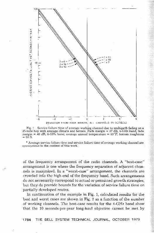
In continuation of the example in Fig. 1, calculated results for the best and worst cases are shown in Fig. 2 as a function of the number of working channels. The best-case results for the 4-GHz band show that the 10 seconds-per-year long-haul objective cannot be met by
1784 THE BELL SYSTEM TECHNICAL JOURNAL, OCTOBER 1979

AVERAGE TERRAIN AND CLIMATEa: 25-MILE PATH" w FADE MARGIN = 37 dB. 4-GHz BAND> = 40 dB. 6-GHz BAND
w a: Q.
gJ Z o ~ 16 Vl
w' :;;; G-GHz
f= WORST CASE ~ 12 => ...J :;;: 10 u. UJ
~ 8 > COMBINED 4-GHz AND 6-GHz:a:
WORST CASE ~ 6
BEST CASE '" w
" 4a: UJ
PROTECTION CHANNELS:><l: 2 ONE___ ___TWO
3 4 5 6 7 8 9 10 11 12 13 14 15 16 17 18
NUMBER OF WORKING CHANNELS
Fig_ 2-Bounding cases for service failure time of average working channels. Frequency assignments are listed in Appendix E.
frequency diversity alone when the number of working channels is larger than seven. The ripple in the worst case is caused by the alternating 20-MHz and 60-MHz increments as channels are added,
In the 6-GHz band, the long-haul objective cannot be met by frequency diversity alone when the number of working channels is larger than four. The 6-GHz worst case is better than the 4-GHz worst case because the 6-GHz fade margin is larger than the 4-GHz fade margin in this example.
In a combined protection system for the two frequency bands, introduced after the 4-GHz band is fully developed, the arrangement of the channels in the 6-GHz band has!only a small effect on the service failure time of an average channel, which varies between 5 and 6 seconds per year.
V. EFFECT OF CHANNELS WITH REDUCED FADE MARGINS
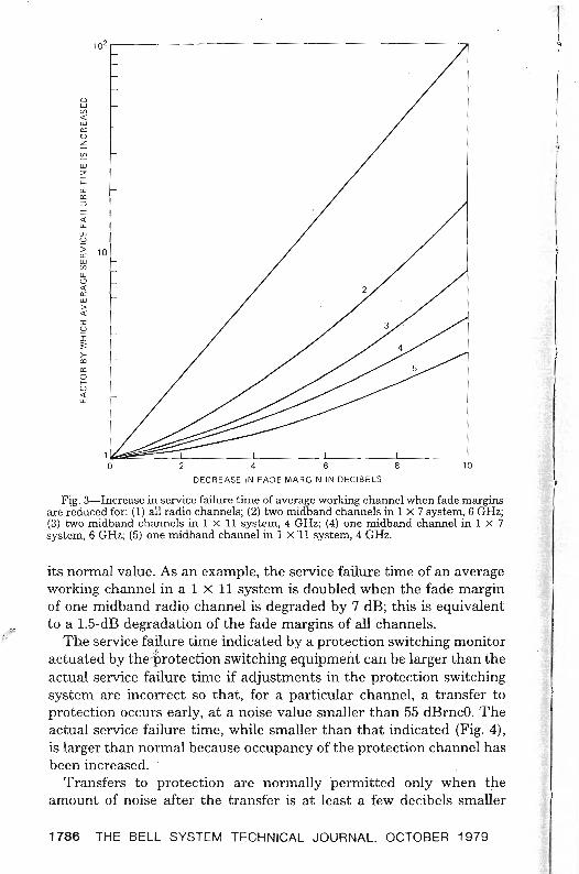
A radio channel with a substandard fade margin experiences a failure time that is larger than normal. The presence of such a channel increases protection unavailability, which results in increased service failure times for all working channels. The increase in the service failure time of an average working channel, caused by the presence of one or two substandard radio channels on a fully developed route, is shown in Fig. 3 as a function of the reduction of the fade margin from
TRANSMISSION UNAVAILABILITY 1785
l102 , )l " I
~ / I- f 0 w (/)
« w a: U ~
~
W :2
f-w a: =' -' « u. w
;;U
a: w (/)
UJ <:J « a: w > « I S2 I :;: >'" a: 0 f-U « u.
4 6 8 10
DECREASE IN FADE MARGIN IN DECIBELS
Fig. 3-Increase in service failure time of average working channel when fade.margins are reduced for: (1) all radio channels; (2) two midband channels in 1 x 7 system, 6 GHz; (3) two midband channels in 1 x 11 system, 4 GHz; (4) one midband channel in 1 x 7 system, 6 GHz; (5) one midband channel in 1 X 11 system, 4 GHz.
its normal value. As an example, the service failure time of an average working channel in a 1 x 11 system is doubled when the fade margin of one midband radiQ channel is degraded by 7 dB; this is equivalent to a 1.5-dB degradation of the fade margins of all channels.
:'(.;
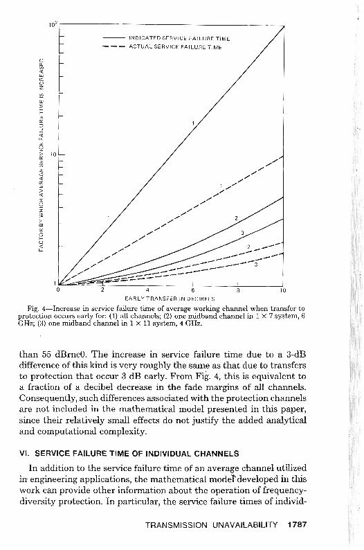
The service failure time indicated by a protection switching monitor actuated by the'protection switching equipment can be larger than the actual service failure time if adjustments in the protection switching system are incorrect so that, for a particular channel, a transfer to protection occurs early, at a noise value smaller than 55 dBrncO. The actual service failure time, while smaller than that indicated (Fig. 4), is larger than normal because occupancy of the protection channel has been increased.
Transfers to protection are normally permitted only when the amount of noise after the transfer is at least a few decibels smaller
1786 THE BELL SYSTEM TECHNICAL JOURNAL, OCTOBER 1979
-- --
1021~--===----_~__ . --- INDICATED ·SERVICE FAI LURE TIME
--- ACTUAL SERVICE FAILURE TIME
0 W if> « w c:: u z ~
w :;;; i= w c:: => .J
:1. w u :; 10c:: w (j)
w <.9 «c::
>w
« I U I ;;: >'"c:: 0 f
« 2 __--LL
U
--...----- ------ _.-. _--~ _--- 3
~--=--;:::--=--:=----- I 1 ~=-' I I I o 2 4 6 8 10
EARLY TRANSFER IN DECIBELS
Fig. 4-Increase in service failure time of average working channel when transfer to protection occurs early for: (1) all channels; (2) one midband channel in 1 x 7 system, 6 GHz; (3) one midband channel in 1 x 11 system, 4 GHz.
than 55 dBmcO. The increase in service failure time due to a 3-dB difference of this kind is very rougWy the same as that due to transfers to protection that occur 3 dB early. From Fig. 4, this is equivalent to a fraction of a decibel decrease in the fade margins of all channels. Consequently, such differences associated with the protection channels are not included in the mathematical model presented in this paper, since their relatively small effects do not justify the added analytical and computational complexity. .
VI. SERVICE FAILURE TIME OF INDIVIDUAL CHANNELS
In addition to the service failure time of an average channel utilized l in engineering applications, the mathematical moder-developed in this work can provide other information about the operation of frequencydiversity protection. In particular,the service failure times of individ-
TRANSMISSION UNAVAILABILITY 1787
ual working channels can be obtained from a decomposition of the facility serVice failure time.
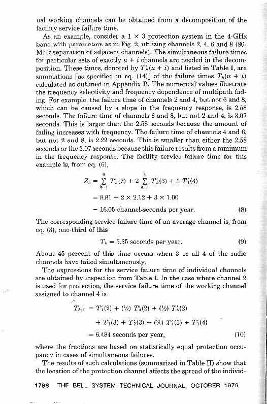
As an example, consider a 1 X 3 protection system in the 4-GHz band with parameters as in Fig. 2, utilizing channels 2, 4, 6 and 8 (80MHz separation of adjacent channels). The simultaneous failure times for particular sets of exactly u + i channels are needed in the decomposition. These times, denoted by Tj, (u + i) and listed in Table I, are summations [as specified in eq. (14)J of the failure times Tk(u + i) calculated as outlined in Appendix B. The numerical values illustrate the frequency selectivity and frequency dependence of multipath fading. For example, the failure time of channels 2 and 4, but not 6 and 8, which can be caused by a slope in the frequency response, is 2.58 seconds. The failure time of channels 6 and 8, but not 2 and 4, is 3.07 seconds. This is larger than the 2.58 seconds because the amount of fading increases with frequency. The failure time of channels 4 and 6, but not 2 and 8, is 2.22 seconds. This is smaller than either the 2.58 seconds or the 3.07 seconds because this failure results from a minimum in the frequency response. The facility serVice failure time for this example is, from eq. (6),
Zh = 2: T/,(2) + 2 2.: T/,(3) + 3 T~(4)
k-I k-l
= 8.81 + 2 X 2.12 + 3 X 1.00
= 16.05 channel-seconds per year. (8)
The corresponding service failure time of an average channel is, from eq. (3), one-third ofthis
Th = 5.35 seconds per year. (9)
About 45 percent of this time occurs when 3 or all 4 of the radio channels have failed simultaneously.
The expressions for the serVice failure time of individual channels are obtained by inspection from Table 1. In the case where channel 2 is used for protection, the service failure time of the working channel assigned to channel 4 is
~,
I
Th ,4 = T~ (2) + (V2) T~ (2) + (%) n (2)
+ T~(3) + T z(3) + (%) T~(3) + T;(4)
= 6.484 seconds per year, (10)
where the fractions are based on statistically equal protection occupancy in cases of simultaneous failures.
The results of such calculations (summarized in Table II) show that the location of the protection channel affects the spread of the individ
1788 THE BELL SYSTEM TECHNICAL JOURNAL, OCTOBER 1979
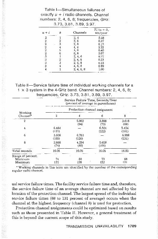
Table I-Simultaneous failures of exactly u + i radio channels. Channel numbers: 2, 4, 6, 8; frequencies, GHz:
3.73, 3.81, 3.89, 3.97.
u+i k Channels T.'(u + i), sec/year
2 1 2, 4 2.58 2 2 2, 6 0.37 2 3 2,8 0.17. 2 4 4, 6 2.22 2 5 4, 8 0.40 2 6 6,8 3.07 3 1 2, 4, 6 0.77 3 2 2,4,8 0.23 3 3 2, 6, 8 0.23 3 4 4,6,8 0.89 4 1 2,4,6,8 1.00
Table II-Service failure time of individual working channels fora 1 X 3 system in the 4-GHz band. Channel numbers: 2, 4, 6, 8;
frequencies, GHz: 3.73, 3.81, 3.89, 3.97. Service Failure Time, Seconds/Year (percent of average in parentheses)
Protection channel assignment Working Channel' 2 4 6 8
2 5.003 3.898 3.618 (94) (73) (68)
4 6.484 - 6.524 5.434 (121) (122) (101)
6 5.608 6.753 - 6.998 (105) (126) (131)
8 3.958 4.294 5.628 (74) (80) (105)
Total seconds 16.05 16.05 16.05 16.05
Range of percent: Minimum 74 80 73 68 Maximum 121 126 122 131
, Working channels in this table are identified by the number of the corresponding regular radio channel.
ual service failure times. The facility service failure time and, therefore, the service failure time of an average channel are not affected by the location of the protection channel. The largest spread of the individual service failure times (68 to 131 percent of average) occurs when the channel at the highest frequency (channel 8) is used for protection.
Protection channel assignments could be optimized based on results such as those presented in Table II. However, a general treatment of this is beyond the current scope of this study.
TRANSMISSION UNAVAILABILITY 1789
VII. ADDITION OF SPACE DIVERSITY TO FREQUENCY DIVERSITY
Space-diversity protective switching capitalizes on the spatial selectivity of the multipath fading process, where, at an instant in time and at a given radio frequency, the strength of the received signal is a random function of location along the height of the receiving tower.6,7.9 For FM radio carrying analog message traffic, space-diversity in most cases in the Bell System consists of two vertically separated receiving antennas and, for each radio channel, a waveguide switch that connects a receiver to either of the two antennas. The switch is activated when the receiver input decreases below a threshold.
The presence of digital traffic in the FM radio network affects the choice of timing in the switch. The number of antenna-to-antenna transfers should be as small as possible, since these can cause errors in digital transmission. For thresholds corresponding to fades deeper than about 35 dB, this is accomplished when, in the case of simultaneous fading on the two antennas, the interval between repeated transfers is 10 seconds. Intervals longer than this cause significant increases in the service failure time of analog message circuits.
When added to frequency-diversity to reduce service failure time, space-diversity is activated before frequency-diversity to avoid undesirable interactions of the two protection systems. Currently, frequency-diversity is activated at a noise threshold of 55 dBrncO, and 52 dBrncO is the desired threshold value for space-diversity activation when it is added to frequency-diversity. Such an arrangement has assured orderly evolution and uniform maintenance procedures of protection switching systems. In the future, because of increased use of space-diversity, changed threshold values may be desirable, ideally 58 dBrncO for frequency-diversity and 55 dBrncO for space-diversity, to further reduce service impairments.
The reduced service failure time resulting from an addition of space diversity in the manner described above can be calculated from eq. (7)
with the values of Tk(u + i) divided by the appropriate improvement ,..-: value for threshold-switched space-diversity.9 Such calculations, which
can be readily incorporated in a computer program, will not be pursued in this pap~r where the emphasis is on an exploration of frequencydiversity behavior.
VIII. ACKNOWLEDGMENTS
We wish to express our appreciation to W. T. Barnett, whose model of simultaneous fading we utilize, and to H. Adams, who helped to develop the computer program.
1790 THE BELL SYSTEM TECHNICAL JOURNAL, OCTOBER 1979
APPENDIX A
Derivation of the Alternating Series
Generally, we prefer to describe fading in terms of time rather than in terms of probability, since the latter description can lead to inadvertent confusion because of the nonstationarity of the fading process. However, for the purposes of combinatorial manipulation, Th can be converted to a fraction designating a probability
Ph = Th/Tb , (11)
where T b is an observation period (time base) such as a year. From eqs. (3) and (6),
N
Ph = N- 1 2: iP'(u + i), (12) i-I
where
P'(u + i) = T'(u + i)/Tb• (13)
To derive the alternating series from eq. (12), we apply a theorem from probability theory (page 77 in Ref. 14). According to it, the probability that exactly u + i out of M channels fail simultaneously is
M
P'(u + i) = L (-lr- u-
iC:+ i S(r), (14) r ....u+i
where J(r)
S(r) = 2: Pk(r) (15) k-I
in which J(r) is the binomial coefficient C~, and where, in the context of this work,
Pk(r) = Tk(r)/Tb .! (16)
After substitution into eq. (12), and collection of like terms,
N i
Ph = N- I 2: 2: (-l)i+PpC~t~S(u + i). (17) i-I p~l
Application of the recursion relationship
C': = C':~ + 2C':~? + C,:-2 (18)
reveals that, because of cancellation of terms, i
2: (-I)P+lpC~t~ = C~~(-2. (19) p=1
TRANSMISSION UNAVAILABILITY 1791
Therefore N
Ph = N- 1 L (-1)i-1C~~~-2S(U + i). (20) i=l
After multiplication by NTb , this becomes the alternating series expression for Zh in eq (7).
APPENDIX B
Simultaneous Failure of Radio Channels
In the case of a single radio channel, the annual amount of time during which the received signal is below a level, as a result of multipath fading, iss. 9
T = rToL 2, L <0.1, (21)
where L describes a normalized voltage such that the level in decibels relative to a nonfaded received signal is 20 log L. For a fade margin of F dB, where F is a positive number, the corresponding voltage level is
L = 1O-cF/20).o (22)
When Lo is used as value of Lin eq. (21), T becomes the time during which the channel has failed, where failure is defined as noise in excess of 55 dBmcO. The quantity To is a time interval related to the length ofthe fading season [eq. (20) in Ref. 9]. The fade occurrence factor iss.9
r = cU/4)D31O-S, (23)
where D is the path length in miles, {is the carrier frequency in gigahertz, and c describes the climate and terrain (eqs. (4) and (5) in Ref. 9). The value of c is unity when the climate and terrain are average.
Empirical expressions for simultaneous fading of radio channels have been obtained by W. T. Barnett from experimental data. From these, expressed in a form similar to that for a single channel, the time during which U + .i radio channels have failed simultaneously is
,'~; Tk(u + i) = rk(u + i)ToL~, (24)
where the SUbscript k is used to identify various sets of u + i channels. This expression is valid when Tk(u + i) is smaller than the values of T for the channels in question. The simultaneous failure time varies with fade margin more than the single channel failure time (L~ versus L5 variation). The quantity Lo describes the actual fade margin when it is the same for all channels. In the case of channels with differing fade margins, Lo describes a nominal fade margin, and the description of differences from it is contained in rk(u + i). The occurrence factor is
rk(u + i) = (cD41O-s/400) (k(U + i), (25)
1792 THE BELL SYSTEM TECHNICAL JOURNAL, OCTOBER 1979
where
l(u+i)
(k(U + i) = (U + i)/2: (Lo/Llp)2(Lo/Lzp)2(Op/(j,). (26)p-I
The quantities in this expression are associated with pairs of channels formed from the u + i channels. The number of such pairs is
I(u + i) = C~+I. (27)
The subscript p identifies the pairs. The fade margins of the channels in a pair are described by LIp and L zp . The corresponding carrier frequencies ftp and hp are expressed in gigahertz ({Ip < (2p). The average frequency for a pair is
{p = (!Jp + (2p) /2 (28)
and the fractional frequency difference is
Op = (f2p - !Jp)/{p. (29)
A value of 0.05 is used for op when one of the channels is in the 4-GHz band and the other in the 6-GHz band.
APPENDIX C
Computation of Combinations of Channels
The evaluation of ZA in eq. (7) requires identification of the combinations of r frequencies that can be formed from the M carrier frequencies of the radio channels. If the frequencies are tagged using the integers 1 through M, then the combinations required are subsets of the set {I, 2, "', M}. The integers appearing in the subsets serve as pointers (used pairwise) to precalculated values of op/{~ for frequency pairs in a subset [eqs. (28) and (29)].
Given M and r, the computation is initialized by defining (for i = 1, 2, "', r)
ai = L, i"" r (30)
ai = (r - 1), L = r (31)
f3i = M - r + i. (32)
The subsets are then generated as follows: (i) Starting withj = r, find the firstj such that a} < f3}. (ii) Replace a} with a} + 1. (iii) For k = (j + 1), (j + 2), "', r replace ak with ak-l + 1.
In this procedure, elements of subsets are incremented to form new subsets, and the elements of each subset are ordered within the vector a such that a} < aj+l. Repeated generation of the same combination of
TRANSMISSION UNAVAILABILITY 1793
frequencies is thereby avoided. The first iteration after initialization produces the subset {I, 2, ... , r}. The iteration is continued until execution of step (i) fails, when all the required C~ combinations have been produced. The potentially large number of combinations necessitates double precision computation in summations over the subsets.
APPENDIX D
Frequency-Diversity Parameters
The service failure time of an average channel can be expressed as
Th = Tuh/lh, (33)
where TUh is the unprotected service failure time for the hop in question obtained from eq. (21) after substitution of Lo from eq. (22). The improvement resulting from the use of frequency-diversity protection is
h = qLo2, (34)
where
q = 100 fo/DC, (35)
in which D is the path length in miles and fo is the frequency in gigahertz at which TUh is calculated. An average of the carrier frequencies of the radio channels is a suitable value for the reference frequency fo. Alternatively, fo can be the center frequency of a band, which facilitates band identification when the calculations are performed for frequency plans formulated by the International Radio Consultative Committee (ccm). The parameter G is determined by the carrier frequencies of the radio channels and by the channel-to-channel variations of fade margins
N J(u+i)
G = N- 1 L: L: (-1)i-1C~~i-2fk(U + i), (36) i-I k=1
where fk(U + i) and the summation are defined in Appendix B. In the simple case of 1 x 1 frequency diversity with the same fade margin for both channels,".
G = 2f~/D.f, (37)
where fp is the average and Af is the difference of the two carrier frequencies, expressed in GHz. The corresponding value of q in this 1 x 1 case,
q = (fo/fp)(50/fpD)(Af/fp) (38)
has been used previously with the factor fo/fp approximated by unity.9 When the fade margins of all radio channels are identical, the
1794 THE BELL SYSTEM TECHNICAL JOURNAL, OCTOBER 1979
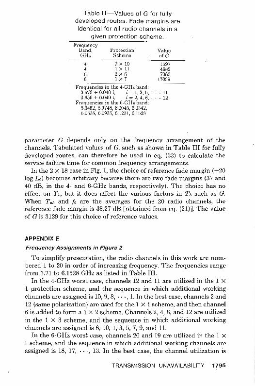
Table III-Values of G for fully developed routes. Fade margins are identical for all radio channels in a
given protection scheme. Frequency
Band, Protection Value GHz Scheme ofC
4 2 x 10 1597 4 1 X 11 4682 6 2x6 7380 6 1 x 7 17059
Frequencies in the 4-GHz band: 3.670 + 0.040 i, i = 1, 3, 5, . . . 11 3.650 + 0.040 i, i = 2, 4, 6, . . . 12
Frequencies in the 6-GHz band: 5.9452, 5.9748, 6.0045, 6.0342, 6.0638,6.0935,6.1231,6.1528
parameter G depends only on the frequency arrangement of the channels. Tabulated values of G, such as shown in Table III for fully developed routes, can therefore be used in eq. (33) to calculate the service failure time for common frequency arrangements.
In the 2 X 18 case in Fig. 1, the choice of reference fade margin (-20 log Lo) becomes arbitrary because there are two fade margins (37 and 40 dB, in the 4- and 6-GHz bands, respectively). The choice has no effect on Th, but it does affect the various factors in Th such as G. When Tuh and to are the averages for the 20 radio channels, the reference fade margin is 38.27 dB [obtained from eq. (21)]. The value of G is 3129 for this choice of reference values.
APPENDIX E
Frequency Assignments in Figure 2
To simplify presentation, the radio channels in this work are numbered 1 to 20 in order of increasing frequency. The frequencies range from 3.71 to 6.1528 GHz as listed in Table III.
In the 4-GHz worst case, channels 12 and 11 are utilized in the 1 X
1 protection scheme, and the sequence in which additional working channels are assigned is 10, 9, 8, .. " 1. In the best case, channels 2 and 12 (same polarization) are used for the 1 X 1 scheme, and then channel 6 is added to form a 1 X 2 scheme. Channels 2, 4, 8, and 12 are utilized in the 1 X 3 scheme, and the sequence in which additional working channels are assigned is 6, 10, 1,3, 5, 7, 9, and 11.
In the 6-GHz worst case, channels 20 and 19 are utilized in the 1 X
1 scheme, and the sequence in which additional working channels are assigned is 18, 17, "', 13. In the best case, the channel utilization is
TRANSMISSION UNAVAILABILITY 1795
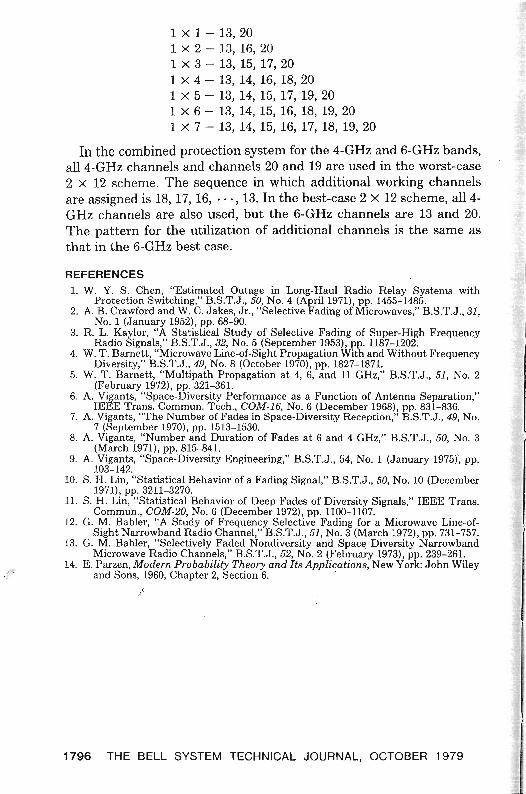
1 x 1 - 13,20 1 x 2 - 13, 16, 20 1 X 3 - 13, 15, 17,20 1 X 4 - 13, 14, 16, 18, 20 1 X 5 - 13, 14, 15, 17, 19,20 1 X 6 - 13, 14, 15, 16, 18, 19, 20 1 X 7 - 13, 14, 15, 16, 17, 18, 19,20
In the combined protection system for the 4-GHz and 6-GHz bands, all4-GHz channels and channels 20 and 19 are used in the worst-case 2 X 12 scheme. The sequence in which additional working channels are assigned is 18, 17, 16, .. " 13. In the best-case 2 X 12 scheme, all 4GHz channels are also used, but the 6-GHz channels are 13 and 20. The pattern for the utilization of additional channels is the same as that in the 6-GHz best case.
REFERENCES 1.� W.Y. S. Chen, "Estimated Outage in Long-Haul Radio Relay Systems with
Protection Switching," B.S.T.J., 50, No.4 (April 1971), pp. 1455-1485. 2.� A. B. Crawford and W. C. Jakes, Jr., "Selective Fading of Microwaves," B.S.T.J., 31,
No.1 (January 1952), pp. 68-90. 3.� R. L. Kaylor, "A Statistical Study of Selective Fading of Super-High Frequency
Radio Signals," B.S.T.J., 32, No.5 (September 1953), pp. 1187-1202. 4.� W. T. Barnett, "Microwave Line-of-Sight Propagation With and Without Frequency
Diversity," B.S.T.J., 49, No.8 (October 1970), pp. 1827-1871. 5.� W. T. Barnett, "Multipath Propagation at 4, 6, and 11 GHz," B.S.T.J., 51, No.2
(February 1972), pp. 321-361. 6.� A. Vigants, "Space-Diversity Performance as a Function of Antenna Separation,"
IEEE Trans. Commun. Tech., COM·16, No.6 (December 1968), pp. 831-836. 7.� A. Vigants, "The Number of Fades in Space·Diversity Reception," B.S.T.J., 49, No.
7 (September 1970), pp. 1513-1530. 8.� A. Vigants, "Number and Duration of Fades at 6 and 4 GHz," B.S.T.J., 50, No.3
(March 1971), pp. 815-841. 9.� A. Vigants, "Space-Diversity Engineering," B.S.T.J., 54, No.1 (January 1975)~ pp.
103-142. 10.� S. H. Lin, "Statistical Behavior of a Fading Signal," B.S.T.J., 50, No. 10 (December
1971), pp. 3211-3270. 11.� S. H. Lin, "Statistical Behavior of Deep Fades of Diversity Signals," IEEE Trans.
Commun., cOM·20, No.6 (December 1972), pp. 1100-1107. 12.� G. M. Babler, "A Study of Frequency Selective Fading for a Microwave Line-of
Sight Narrowband Radio Channel," B.S.T.J., 51, No.3 (March 1972), pp. 731-757. 13.� G. M. Babler, "Selectively Faded Nondiversity and Spac~ Diversity Narrowband
Microwave Radio Channels," B.S.T.J., 52, No.2 (February 1973), pp. 239-261. 14. E. Parzen, Modern Probability Theory and Its Applications, New York: John Wiley
/-<: and Sons, 1960, Chapter 2, Section 6.
.f
1796 THE BELL SYSTEM TECHNICAL JOURNAL, OCTOBER 1979