transmitters: honeywell st 3000 smart transmitter … · like other honeywell transmitters, the st...
TRANSCRIPT
ST 3000 Smart Transmitter Series 100 Remote Diaphragm Seals Models STR12D 0-10 to 0-400 inH2O 0-25 to 0-1000 mbar STR13D 0-5 to 0-100 psid 0-0.35 to 0-7 bar STR14G 0-5 to 0-500 psig 0-0.35 to 0-35 bar STR17G 0-100 to 0-3000 psig 0-7 to 0-210 bar STR14A 0-5 to 0-500 psia 0-0.35 to 0-35 bar
34-ST-03-64 7/04
Specification and Model Selection
Guide In 1983, Honeywell introduced the first Smart Pressure Transmitter― the ST 3000®. In 1989, Honeywell launched the first all digital, bi-directional protocol for smart field devices. Today, its ST 3000 Series 100 Remote Seal Transmitters continue to bring proven “smart” technology to a wide spectrum of measurement applications. Typical applications include high accuracy level measurement in pressurized vessels in the chemical and hydrocarbon processing industries. A second application consists of accurate flow measurement for slurries and high viscosity fluids in the chemical industry. Honeywell remote seal transmitters demonstrate proven reliability in hundreds on installations in a wide variety of industries and applications with a wide variety of secondary fill fluids for corrosive or high temperature process fluids. All ST 3000 transmitters can provide a 4-20 mA output, Honeywell Digitally Enhanced (DE) output, HART* output, or FOUNDATION™ Fieldbus output. When digitally integrated with Honeywell’s Process Knowledge System™, EXPERION PKS™, ST 3000 instruments provide a more accurate process variable as well as advanced diagnostics. Honeywell’s high-performance ST 3000 S100 transmitters lead the industry in: • Accuracy • Stability • Reliability • Rangeability • Warranty Includes Lifetime Tranmsitters: • Accuracy = +/-0.0375% • Stability = +/-0.01% per year • Reliability = 470 years MTBF • Rangeability = 400 to 1 • Lifetime Warranty = 15 years
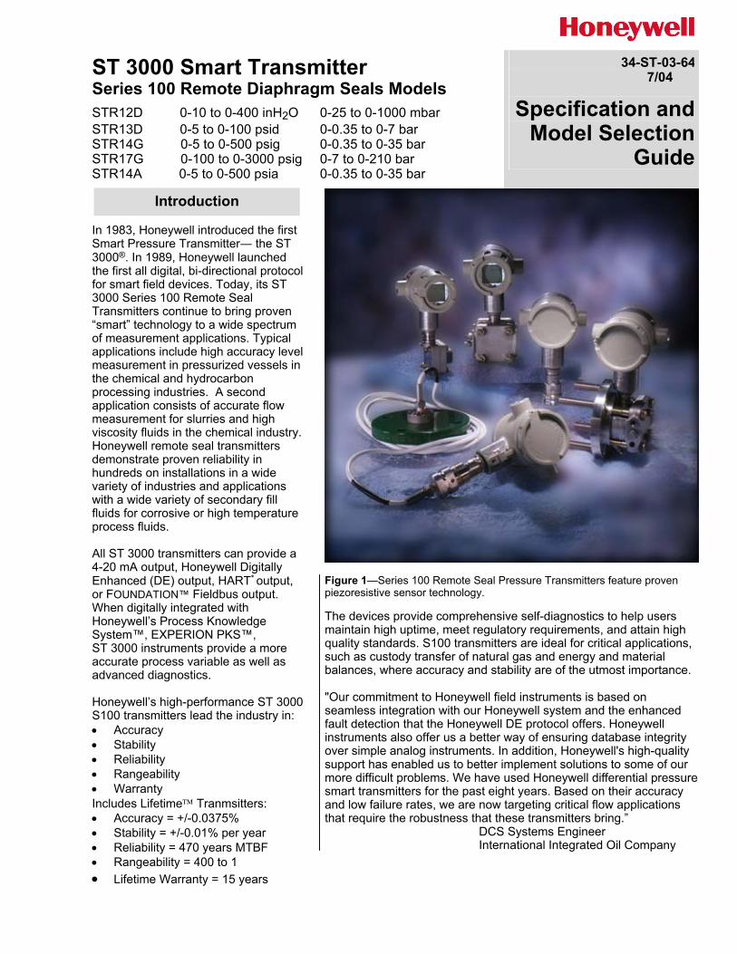
Figure 1—Series 100 Remote Seal Pressure Transmitters feature proven piezoresistive sensor technology. The devices provide comprehensive self-diagnostics to help users maintain high uptime, meet regulatory requirements, and attain high quality standards. S100 transmitters are ideal for critical applications, such as custody transfer of natural gas and energy and material balances, where accuracy and stability are of the utmost importance. "Our commitment to Honeywell field instruments is based on seamless integration with our Honeywell system and the enhanced fault detection that the Honeywell DE protocol offers. Honeywell instruments also offer us a better way of ensuring database integrity over simple analog instruments. In addition, Honeywell's high-quality support has enabled us to better implement solutions to some of our more difficult problems. We have used Honeywell differential pressure smart transmitters for the past eight years. Based on their accuracy and low failure rates, we are now targeting critical flow applications that require the robustness that these transmitters bring.” DCS Systems Engineer International Integrated Oil Company
Introduction
34-ST-03-64 Page 2
Description Features
The ST 3000 transmitter can replace any 4 to 20 mA output transmitter in use today and operates over a standard two-wire system. The measuring means is a piezoresistive sensor, which actually contains three sensors in one. It contains a differential pressure sensor, a temperature sensor, and a static pressure sensor. Microprocessor-based electronics provide higher span-turndown ratio, improved temperature and pressure compensation, and improved accuracy. The transmitter’s meter body and electronics housing resist shock, vibration, corrosion, and moisture. The electronics housing contains a compartment for the single-board electronics, which is isolated from an integral junction box. The single-board electronics is replaceable and interchangeable with any other ST 3000 Series 100 or Series 900 model transmitter. Like other Honeywell transmitters, the ST 3000 features two-way communication between the operator and the transmitter through our Smart Field Configurator (SFC). You can connect the SFC anywhere that you can access the transmitter signal lines. The SCT 3000 Smartline® Configuration Toolkit provides an easy way to configure instruments using a personal computer. The toolkit enables configuration of devices before shipping or installation. The SCT 3000 can operate in the offline mode to configure an unlimited number of devices. The database can then be loaded downline during commissioning.
• Choice of linear or square root output conformity is a simple configuration selection.
• Direct digital integration with Experion PKS and other control systems provides local measurement accuracy to the system level without adding typical A/D and D/A converter inaccuracies.
• Unique piezoresistive sensor automatically compensates input for temperature and static pressure.Added “smart” features include configuring lower and upper range values, simulating accurate analog output, and selecting preprogrammed engineering units for display.
• Smart transmitter capabilities with local or remote interfacing means significant manpower efficiency improvements in commissioning, start-up, and ongoing maintenance functions.

34-ST-03-64 Page 3
Specifications Operating Conditions – All Models
Parameter Reference Condition Rated Condition Operative Limits Transportation and Storage
°C °F °C °F °C °F °C °F
Ambient Temperature * 25 ±1 77 ±2 — — — — –55 to 90 –67 to 194
Humidity % RH 10 to 55 0 to 100 0 to 100 0 to 100
Maximum Allowable Working Pressure (MAWP)
MAWP is minimum of Body Rating or Seal Rating (See Model Selection Guide for Seal MAWP)
Body MAWP STR12D 2500 psig (172 bar) STR13D 2500psig (172 bar) STR14G 500 psig (35 bar) STR17G 3000psig (207 bar) STR14A 500 psia (35 bar).
Vacuum Region - Minimum Pressure mmHg absolute
Atmospheric (See Figure 4 for vacuum limitations.)
Supply Voltage, Current, and Load Resistance
Voltage Range: 10.8 to 42.4 Vdc at terminals Current Range: 3.0 to 21.8 mA Load Resistance: 0 to 1440 ohms (as shown in Figure 5)
* Ambient Temperature Limit is a function of Process Interface Temperature. (See Figure 2.)

34-ST-03-64 Page 4
Performance Under Rated Conditions * - Model STR12D (0-10 to 0-400 inH2O) Parameter Description
Upper Range Limit ** inH2O mbar
400 (39.2°F/4°C is standard reference temperature for inH2O range.) 1000
Minimum Span inH2O mbar
10 Note: Recommended minimum span in square root mode is 20 inH2O (50 mbar). 25
Turndown Ratio 40 to 1
Zero Elevation and Suppression No limit except minimum span within ±100% URL.
Accuracy (Reference – Includes combined effects of linearity, hysteresis, and repeatability)
• Accuracy includes residual error after averaging successive readings.
• For FOUNDATION Fieldbus use Digital Mode specifications. For HART use Analog Mode specifications.
In Analog Mode: ±0.2% of calibrated span or upper range value (URV), whichever is greater, terminal based. For URV below reference point (50 inH2O), accuracy equals:
±0.1 + 0.1
50 inH2O
span inH2O or ±0.1 + 0.1 ( )125 mbar
span mbar in % span
In Digital Mode: ±0.175% of calibrated span or upper range value (URV), whichever is greater, terminal based. For URV below reference point (50 inH2O), accuracy equals:
±0.075 + 0.10
50 inH2O
span inH2O or ±0.075 + 0.10 ( )125 mbar
span mbar in % span
Combined Zero and Span Temperature Effect per 28°C (50°F) ***
In Analog Mode: ±1.2% of span.
For URV below reference point (100 inH2O), effect equals:
±0.2 + 1.0
100 inH2O
span inH2O or ±0.2 + 1.0 ( )250 mbar
span mbar in % span
In Digital Mode: ±1.175% of span.
For URV below reference point (100 inH2O), effect equals:
±0.175 + 1.0
100 inH2O
span inH2O or ±0.175 + 1.0 ( )250 mbar
span mbar in % span
* Performance specifications are based on reference conditions of 25°C (77°F), zero (0) static pressure, 10 to 55% RH, and 316L Stainless Steel barrier diaphragm.
** Transmitter URL limit or maximum seal pressure rating, whichever is lower.
*** Apply 1.5 times factor to capillary lengths greater than 10 feet.
34-ST-03-64 Page 5 Performance Under Rated Conditions * - Model STR13D (0-5 to 0-100 psid)
Parameter Description
Upper Range Limit ** psid bar
100 7
Minimum Span psid bar
5 0.35
Turndown Ratio 20 to 1
Zero Elevation and Suppression No limit except minimum span within –18% and +100% of URL. Specifications valid from –5% to 100% of URL.
Accuracy (Reference – Includes combined effects of linearity, hysteresis, and repeatability)
• Stated accuracy does not apply for models with 2.9 inch diameter remote seal diaphragms.
• Accuracy includes residual error after averaging successive readings.
• For FOUNDATION Fieldbus use Digital Mode specifications. For HART use Analog Mode specifications.
In Analog Mode: ±0.1% of calibrated span or upper range value (URV), whichever is greater, terminal based. For URV below reference point (30 psi), accuracy equals:
±0.05 + 0.05 ( )30 psi span psi
or ±0.05 + 0.05 ( )2 bar span bar in % span
In Digital Mode: ±0.075% of calibrated span or upper range value (URV), whichever is greater, terminal based. For URV below reference point (30 psi), accuracy equals:
±0.025 + 0.05 ( )30 psi span psi
or ±0.025 + 0.05 ( )2 bar span bar in % span
Combined Zero and Span Temperature Effect per 28°C (50°F) ***
In Analog Mode: ±0.33% of span. For URV below reference point (30 psi), effect equals:
±0.05 + 0.28 ( )30 psi span psi
or ±0.05 + 0.28 ( )2 bar span bar in % span
In Digital Mode: ±0.305% of span. For URV below reference point (30 psi), effect equals:
±0.025 + 0.28 ( )30 psi span psi
or ±0.025 + 0.28 ( )2 bar span bar in % span
* Performance specifications are based on reference conditions of 25°C (77°F), zero (0) static pressure, 10 to 55% RH, and 316L Stainless Steel barrier diaphragm.
** Transmitter URL limit or maximum seal pressure rating, whichever is lower.
*** Apply 1.5 times factor to capillary lengths greater than 10 feet.
34-ST-03-64 Page 6
Performance Under Rated Conditions * - Model STR14G (0-5 to 0-500 psig) Parameter Description
Upper Range Limit ** psig bar
500 35
Minimum Span psig bar
5 0.35
Turndown Ratio 100 to 1
Zero Elevation and Suppression No limit except minimum span from absolute zero to 100% of URL. Specifications valid over this range.
Accuracy (Reference – Includes combined effects of linearity, hysteresis, and repeatability)
• Accuracy includes residual error after averaging successive readings.
• For FOUNDATION Fieldbus use Digital Mode specifications. For HART use Analog Mode specifications.
In Analog Mode: ±0.1% of calibrated span or upper range value (URV), whichever is greater. For URV below reference point (20 psi), accuracy equals:
±0.05 + 0.05 ( )20 psi span psi
or ±0.05 + 0.05 ( )1.4 bar span bar in % span
In Digital Mode: ±0.075% of calibrated span or upper range value (URV), whichever is greater. For URV below reference point (20 psi), accuracy equals:
±0.025 + 0.05 ( )20 psi span psi
or ±0.025 + 0.05 ( )1.4 bar span bar in % span
Combined Zero and Span Temperature Effect per 28°C (50°F) ***
In Analog Mode: ±1.88% of span.
For URV below reference point (75 psi), effect equals:
±0.2 + 1.68 ( )75 psi span psi
or ±0.2 + 1.68 ( )5.25 bar span bar in % span
In Digital Mode: ±1.855% of span
For URV below reference point (75 psi), effect equals:
±0.175 + 1.68 ( )75 psi span psi
or ±0.175 + 1.68 ( )5.25 bar span bar in % span
* Performance specifications are based on reference conditions of 25°C (77°F), zero (0) static pressure, 10 to 55% RH, and 316L Stainless Steel barrier diaphragm.
** Transmitter URL limit or maximum seal pressure rating, whichever is lower.
*** Apply 1.5 times factor to capillary lengths greater than 10 feet.

34-ST-03-64 Page 7 Performance Under Rated Conditions * - Model STR17G (0-100 to 0-3000 psig)
Parameter Description
Upper Range Limit ** psig bar
3000 210
Minimum Span psig bar
100 7
Turndown Ratio 30 to 1
Zero Elevation and Suppression No limit except minimum span from absolute zero to 100% of URL. Specifications valid over this range.
Accuracy (Reference – Includes combined effects of linearity, hysteresis, and repeatability)
• Accuracy includes residual error after averaging successive readings.
• For FOUNDATION Fieldbus use Digital Mode specifications. For HART use Analog Mode specifications.
In Analog Mode: ±0.15% of calibrated span or upper range value (URV), whichever is greater. For URV below reference point (300 psi), accuracy equals:
±0.10 + 0.05 ( )300 psi span psi
or ±0.10 + 0.05 ( )21 bar span bar in % span
In Digital Mode: ±0.125% of calibrated span or upper range value (URV), whichever is greater. For URV below reference point (300 psi), accuracy equals:
±0.075 + 0.05 ( )300 psi span psi
or ±0.075 + 0.05 ( )21 bar span bar in % span
Combined Zero and Span Temperature Effect per 28°C (50°F) ***
In Analog Mode: ±0.70% of span. For URV below reference point (500 psi), effect equals:
±0.20 + 0.50 ( )500 psi span psi
or ±0.2 + 0.50 ( )34.5 bar span bar in % span
In Digital Mode: ±0.675% of span. For URV below reference point (500 psi), effect equals:
±0.175 + 0.50 ( )500 psi span psi
or ±0.175 + 0.50 ( )34.5 bar span bar in % span
* Performance specifications are based on reference conditions of 25°C (77°F), zero (0) static pressure, 10 to 55% RH, and 316L Stainless Steel barrier diaphragm.
** Transmitter URL limit or maximum seal pressure rating, whichever is lower. *** Apply 1.5 times factor to capillary lengths greater than 10 feet.
34-ST-03-64 Page 8
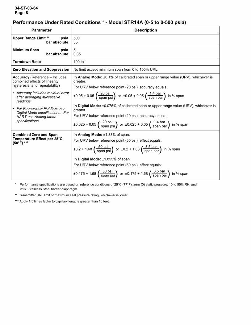
Performance Under Rated Conditions * - Model STR14A (0-5 to 0-500 psia) Parameter Description
Upper Range Limit ** psia bar absolute
500 35
Minimum Span psia bar absolute
5 0.35
Turndown Ratio 100 to 1
Zero Elevation and Suppression No limit except minimum span from 0 to 100% URL.
Accuracy (Reference – Includes combined effects of linearity, hysteresis, and repeatability)
• Accuracy includes residual error after averaging successive readings.
• For FOUNDATION Fieldbus use Digital Mode specifications. For HART use Analog Mode specifications.
In Analog Mode: ±0.1% of calibrated span or upper range value (URV), whichever is greater. For URV below reference point (20 psi), accuracy equals:
±0.05 + 0.05 ( )20 psi span psi
or ±0.05 + 0.05 ( )1.4 bar span bar in % span
In Digital Mode: ±0.075% of calibrated span or upper range value (URV), whichever is greater. For URV below reference point (20 psi), accuracy equals:
±0.025 + 0.05 ( )20 psi span psi
or ±0.025 + 0.05 ( )1.4 bar span bar in % span
Combined Zero and Span Temperature Effect per 28°C (50°F) ***
In Analog Mode: ±1.88% of span. For URV below reference point (50 psi), effect equals:
±0.2 + 1.68 ( )50 psi span psi
or ±0.2 + 1.68 ( )3.5 bar span bar in % span
In Digital Mode: ±1.855% of span For URV below reference point (50 psi), effect equals:
±0.175 + 1.68 ( )50 psi span psi
or ±0.175 + 1.68 ( )3.5 bar span bar in % span
* Performance specifications are based on reference conditions of 25°C (77°F), zero (0) static pressure, 10 to 55% RH, and 316L Stainless Steel barrier diaphragm.
** Transmitter URL limit or maximum seal pressure rating, whichever is lower.
*** Apply 1.5 times factor to capillary lengths greater than 10 feet.

34-ST-03-64 Page 9 Performance Under Rated Conditions – General for all Models
Parameter Description
Output (two-wire) Analog 4 to 20 mA or digital communications DE mode. Options available for FOUNDATION Fieldbus and HART protocol.
Supply Voltage Effect ±0.005% span per volt.
Damping Time Constant Adjustable from 0 to 32 seconds digital damping.
RFI Protection (Standard) Negligible (20 to 1000 MHz at 30 volts per meter).
CE Conformity (Europe) 89/336/EEC, Electromagnetic Compatibility (EMC) Directive.
Physical and Approval Bodies Parameter Description
Process Interface See Model Selection Guide for Material Options for desired seal type. Seal Barrier Diaphgram 316L Stainless Steel, Monel, Hastelloy C, Tantalum
Seal Gasket Materials Klinger C-4401 (non-asbestos) Grafoil
Mounting Bracket Carbon Steel (Zinc-Chromate plated) or Stainless Steel.
Fill Fluid (Meter Body) Silicone (DC 200) S.G. @ 25°C = 0.94 CTFE (Chlorotrifluoroethylene) S.G. @ 25°C = 1.89
Fill Fluid (Secondary) Silicone (DC 200) S.G. @ 25°C = 0.94 CTFE (Chlorotrifluoroethylene) S.G. @ 25°C = 1.89 Silicone (DC 704) S.G. @ 25°C = 1.07 NEOBEE M-20 S.G. @ 25°C = 0.90 Syltherm 800 S.G. @ 25°C = 0.93
Electronic Housing Epoxy-Polyester hybrid paint. Low copper-aluminum alloy. Meets NEMA 4X (watertight) and NEMA 7 (explosion proof). Stainless steel optional.
Capillary Tubing Armored Stainless Steel or PVC Coated Armored Stainless Steel. Length: 5, 10, 15, 20, 25, and 35 feet (1.5, 3, 4.6, 6.1, 7.5, and 10.7 meters). A 2 inch (51 millimeter) S.S. close-coupled nipple is also available. See Model Selection Guide. Refer to Figure 3 for guide to maximum capillary length vs. diaphragm diameter.
Wiring Accepts up to 16 AWG (1.5 mm diameter).
Mounting See Figure 6.
Dimensions Transmitter: See Figures 9 and 10. Seal: See Model Selection Guide.
Net Weight Transmitter: 15.4 pounds (7 Kg). Total weight is dependent on seal type and capillary length.
Approval Bodies
- Hazardous Areas
- Canadian Registration Number (CRN)
Approved as explosion proof and intrinsically safe for use in Class I, Division 1, Groups A, B, C, D locations, and nonincendive for Class I, Division 2, Groups A, B, C, D locations. Approved EEx ia IIC T4, T5, T6 and EEx d IIC T5, T6 per ATEX standards. See attached Model Selection Guide for options.
- All ST 3000 model designs, except STG19L, STG99L, STG170, STG180, have been registered in all provinces and territories in Canada and are marked CRN: 0F8914.5C.
Pressure Equipment Directive (97/23/EC)
The ST 3000 pressure transmitters listed in this Specification have no pressurized internal volume or have a pressurized internal volume rated less than 1,000 bar (14,500 psig) and/or have a maximum volume of less than 0.1 liter. Therefore, these transmitters are either; not subject to the essential requirements of the directive 97/23/EC (PED, Annex 1) and shall not have the CE mark, or the manufacturer has the free choice of a module when the CE mark is required for pressures > 200 bar (2,900 psig).
NOTE: Pressure transmitters that are part of safety equipment for the protection of piping (systems) or vessel(s) from exceeding allowable pressure limits, (equipment with safety functions in accordance with Pressure Equipment Directive 97/23/EC article 1, 2.1.3), require separate examination.

34-ST-03-64 Page 10
20018016014012010080604020
0
185 185165 165
Maximum Ambient Temperature (°F)
140 140
350200 450
Process Interface Temperature (°F) 20385
DP/ILGP/I & AP/I
ST3000
Figure 2—Ambient temperature and process interface chart.
3530252015
10
5
0
MaximumLength (ft.)
1.9 2.4 2.9 3.5 4.1Diaphragm Size (in.)
S100 Remote Seal Maximum Capillary Length
20337
This chart is intended to serveas a guide in selecting theappropriate diaphragm size forthe required capillary length.
DP/ILGP/I & AP/I
ST3000
Figure 3—Maximum capillary length and diaphragm size chart.
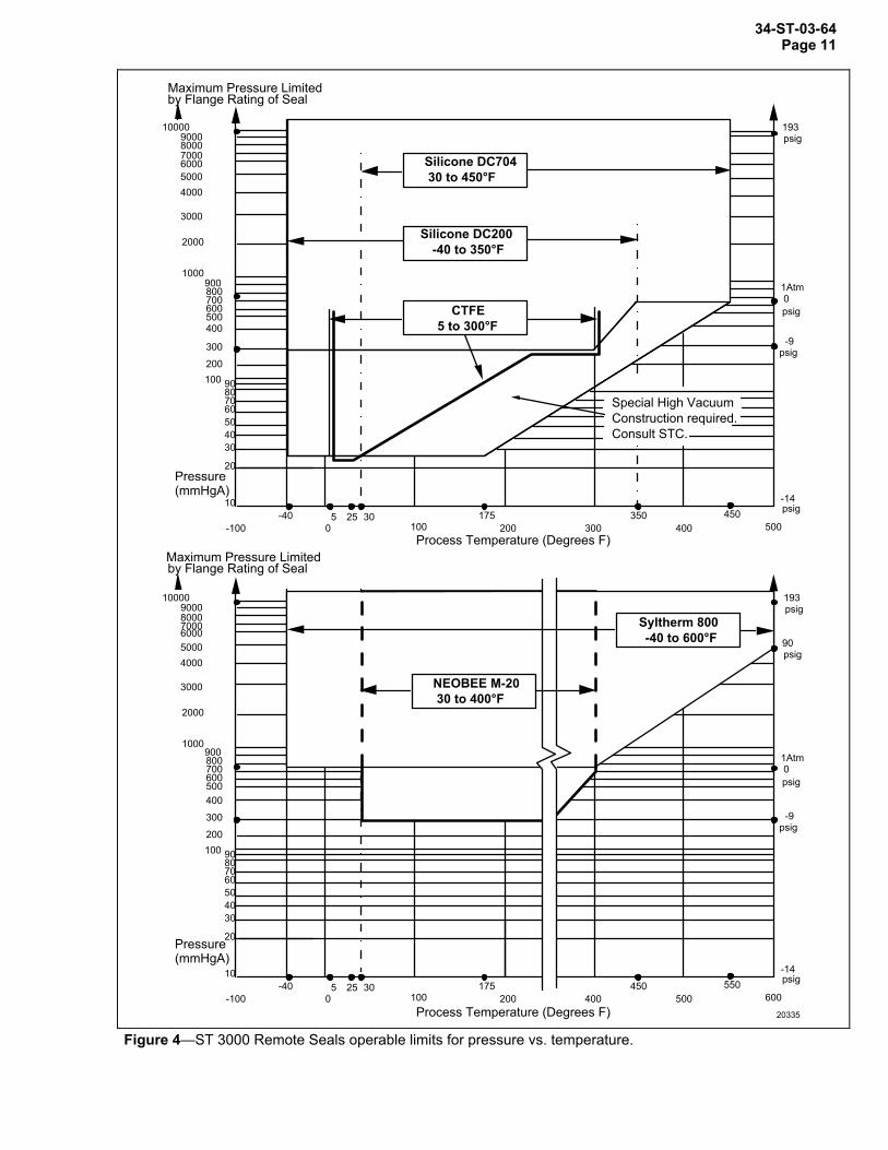
34-ST-03-64 Page 11
1Atm
Special High Vacuum Construction required. Consult STC.
900080007000600050004000
3000
2000
1000
Maximum Pressure Limitedby Flange Rating of Seal
10000
900800700600500400
300
200100 90
807060504030
20
10
Pressure(mmHgA)
-40 5 25 300 100
175 350 450200 300 400 500
psig193
-9psig
-14psig
Process Temperature (Degrees F)-100
Silicone DC704 30 to 450°F
Silicone DC200 -40 to 350°F
CTFE 5 to 300°F
1Atm
900080007000600050004000
3000
2000
1000
Maximum Pressure Limitedby Flange Rating of Seal
10000
900800700600500400
300
200100 90
807060504030
20
10
Pressure(mmHgA)
-40 5 25 300 100
175 450 550200 400 500 600
psig193
-9psig
-14psig
Process Temperature (Degrees F)-100
20335
NEOBEE M-20 30 to 400°F
Syltherm 800 -40 to 600°F
psig90
psig0
psig0
Figure 4—ST 3000 Remote Seals operable limits for pressure vs. temperature.

34-ST-03-64 Page 12
OperatingArea
1440
1200
800
650
450
250
0 10.8 16.28
20.63
25
28.3
37.0
42.4
Supply Voltage
Loop Resistance (ohms)
20338
NOTE: A minimum of 250 ohms of loop resistance is necessary to support communication. Loop resistance equals barrier resistance plus wire resistance plus receiver resistance. Also, 45 volt operation is permitted if not an intrinsically safe installation.
Figure 5—Supply voltage/loop resistance chart.
Variableref. legHead
H1
LP Side
HP Side
H2Fixed
24249
Maximum level
Minimum level.
NOTE: Lower flange seal should not be mounted over 22 feet below or above the transmitter for silicone fill fluid (11 feet for CTFE fill fluid) with tank at one atmosphere. The combination of tank vacuum and high pressure capillary head effect should not exceed 9 psi vacuum (300 mmHg absolute). Consult Honeywell for installation of STR13D.
Figure 6—The ST 3000 transmitter with remote diaphragm seals shown mounted on a tank.
34-ST-03-64 Page 13
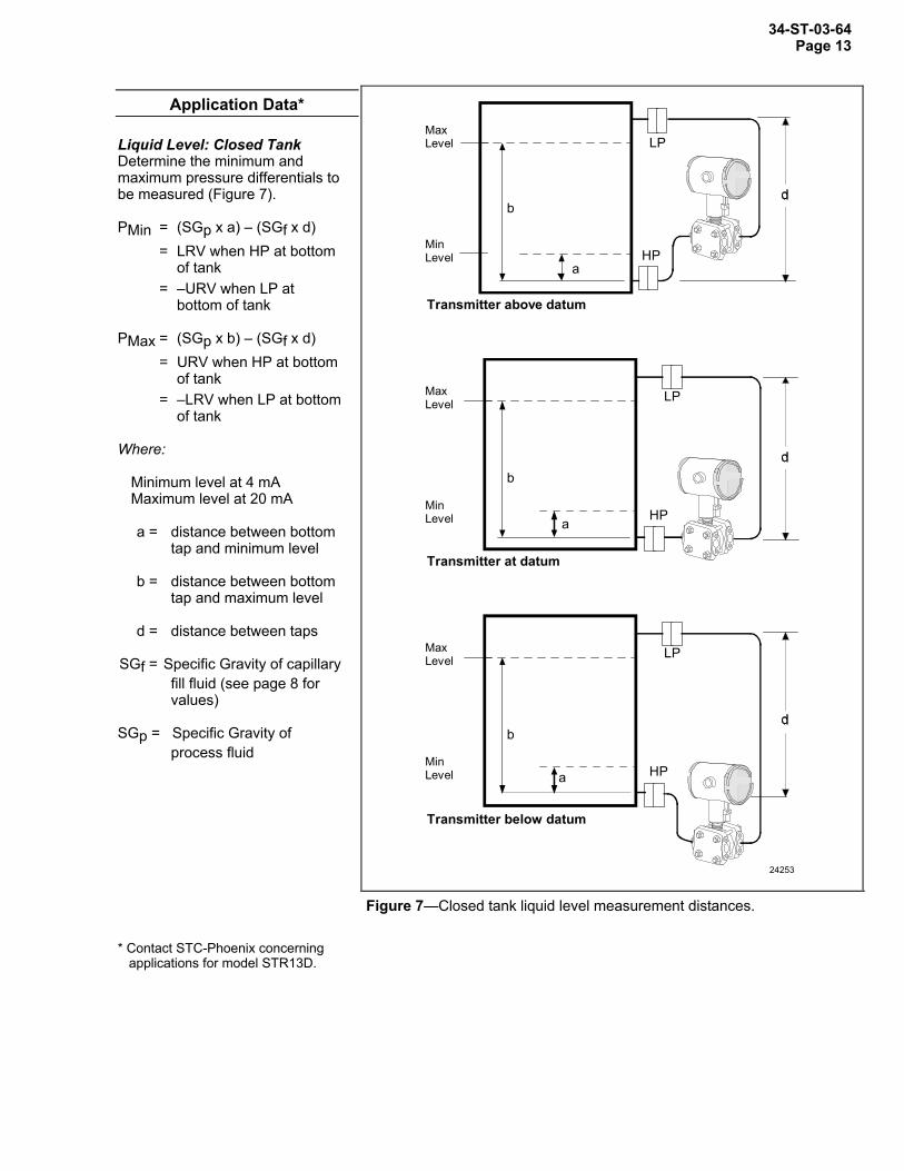
Application Data*
Liquid Level: Closed Tank Determine the minimum and maximum pressure differentials to be measured (Figure 7). PMin = (SGp x a) – (SGf x d) = LRV when HP at bottom
of tank = –URV when LP at
bottom of tank PMax = (SGp x b) – (SGf x d) = URV when HP at bottom
of tank = –LRV when LP at bottom
of tank Where: Minimum level at 4 mA Maximum level at 20 mA a = distance between bottom
tap and minimum level b = distance between bottom
tap and maximum level d = distance between taps SGf = Specific Gravity of capillary
fill fluid (see page 8 for values)
SGp = Specific Gravity of
process fluid
b
a
LP
HP
24253
MaxLevel
MinLevel
Transmitter above datum
LP
HP
b
a
MaxLevel
MinLevel
Transmitter at datum
LP
HP
b
a
MaxLevel
MinLevel
Transmitter below datum
Figure 7—Closed tank liquid level measurement distances. * Contact STC-Phoenix concerning applications for model STR13D.
34-ST-03-64 Page 14
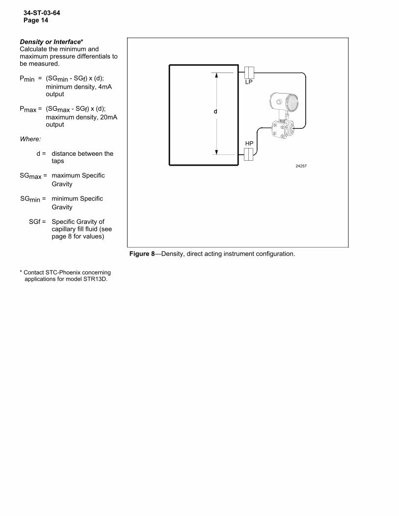
Density or Interface* Calculate the minimum and maximum pressure differentials to be measured. Pmin = (SGmin - SGf) x (d);
minimum density, 4mA output
Pmax = (SGmax - SGf) x (d);
maximum density, 20mA output
Where: d = distance between the
taps SGmax = maximum Specific
Gravity SGmin = minimum Specific
Gravity SGf = Specific Gravity of
capillary fill fluid (see page 8 for values)
LP
HP
24257
Figure 8—Density, direct acting instrument configuration. * Contact STC-Phoenix concerning applications for model STR13D.
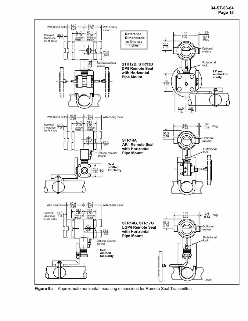
34-ST-03-64 Page 15
STR12D, STR13D DP/I Remote Seal with Horizontal Pipe Mount
STR14A AP/I Remote Seal with Horizontal Pipe Mount
Reference Dimensions:millimeters
inches
STR14G, STR17G LGP/I Remote Seal with Horizontal Pipe Mount
Optional external ground
45.7 1.8
53.1 2.09Removal
Clearance for All Caps
82.9 3.26With Smart meter
Withoutmeter
With Analog meter
94.9 3.74
65.12.56Withoutmeter
23.5 .925
1355.32
3.60.14 Plug
Optional meters
Rotational lock
55.3 2.18
24261
1355.32
3.60.14
Plug
Optional meters
Rotational lock
55.3 2.18
Optional external ground
45.7 1.8
53.1 2.09Removal
Clearance for All Caps
82.9 3.26With Smart meter
Withoutmeter
With Analog meter94.9 3.74
65.12.56Withoutmeter
23.5 .925
Seal omitted for clarity
Optional external ground
Seal omitted for clarity
45.7 1.8
53.1 2.09Removal
Clearance for All Caps
71.1 2.80 SQ.
82.9 3.26With Smart meter
Withoutmeter
With Analog meter94.9 3.74
65.12.56Withoutmeter
23.5 .925
1355.32
LP seal omitted for clarity
3.60.14Plug
Optional meters
Rotational lock
42.51.67
501.97
853.35
55.3 2.18
Figure 9a —Approximate horizontal mounting dimensions for Remote Seal Transmitter.

34-ST-03-64 Page 16
STR14G, STR17G LGP/I Remote Seal with Vertical Pipe Mount (Flat Bracket)
STR12D, STR13D DP/I Remote Seal with Vertical Pipe Mount
STR14A AP/I Remote Seal with Vertical Pipe Mount
Reference Dimensions:millimeters
inches
Seal omitted for clarity
853.35
LP seal omitted for clarity
SQ
42.5 1.67
50 1.97
1355.32
3.60.14Plug
Optional meters
Rotational lock
55.3 2.18
1355.32
3.60.14 Plug
Optional meters
Rotational lock
55.3 2.18
24262
1355.32
3.60.14 Plug
Optional meters
Rotational lock
55.3 2.18
Optional external ground
45.7 1.8
53.1 2.09Removal
Clearance for All Caps
82.9 3.26With Smart meter
Withoutmeter
With Analog meter
94.9 3.74
65.12.56Withoutmeter
23.5 .925
Optional external ground
45.7 1.8
53.1 2.09Removal
Clearance for All Caps
82.9 3.26
With Smart meter
Withoutmeter
With Analog meter
94.9 3.74
65.12.56Withoutmeter
23.5 .925
71.1 2.80 SQ.
Optional external ground
45.7 1.8
53.1 2.09Removal
Clearance for All Caps
82.9 3.26With Smart meter
Withoutmeter
With Analog meter
94.9 3.74
65.12.56Withoutmeter
23.5 .925
Seal omitted for clarity
Figure 9b —Approximate vertical mounting dimensions for Remote Seal Transmitter.

34-ST-03-64 Page 17
Options Ordering Information Mounting Bracket The angle mounting bracket is available in either zinc-plated carbon steel or stainless steel and is suitable for horizontal or vertical mounting on a two inch (50 millimeter) pipe, as well as wall mounting. An optional flat mounting bracket is also available in carbon steel for two inch (50 millimeter) pipe mounting. Indicating Meter (ME and SM Options) Two integral meter options are available. An analog meter (option ME) is available with a 0 to 100% linear scale. The Smart Meter (option SM) provides an LCD display for both analog and digital output and can be configured to display pressure in pre-selected engineering units. HART Protocol Compatibility (Option HC) An optional electronics module is available for the ST 3000 that provides HART Protocol compatibility. Transmitters with the HART Option are compatible with the AMS System. (Contact your AMS Supplier if an upgrade is required.) Lightning Protection (Option LP) A terminal block with circuitry that protects the transmitter from transient surges induced by nearby lightning strikes is available.
Indicator Configuration (Option CI) Provides custom configuration of Smart Meters Tagging (Option TG) Up to 30 characters can be added on the stainless steel nameplate mounted on the transmitter’s electronics housing at no extra cost. Note that a separate nameplate on the meter body contains the serial number and body-related data. A stainless steel wired on tag with additional data of up to 4 lines of 28 characters is also available. The number of characters for tagging includes spaces. Transmitter Configuration (Option TC) The factory can configure the transmitter linear/square root extraction, damping time, LRV, URV and mode (analog/digital) and enter an ID tag of up to eight characters and scratchpad information as specified. Custom Calibration and ID in Memory (Option CC) The factory can calibrate any range within the scope of the transmitter’s range and enter an ID tag of up to eight characters in the transmitter’s memory. FOUNDATION Fieldbus (Option FF) Equips transmitter with FF protocol for use in 31.25 kbit/s FF networks. See document 34-ST-03-72 for additional information on ST 3000 Fieldbus transmitters.
Contact your nearest Honeywell sales office, or
In the U.S.:
Honeywell Industrial Automation & Control
16404 North Black Canyon Hwy. Phoenix, AZ 85053
1-800-288-7491
In Canada: The Honeywell Centre 155 Gordon Baker Rd.
North York, Ontario M2H 3N7 1-800-461-0013
In Latin America:
Honeywell Inc. 480 Sawgrass Corporate Parkway,
Suite 200 Sunrise, FL 33325
(954) 845-2600
In Europe and Africa: Honeywell S. A.
Avenue du Bourget 1 1140 Brussels, Belgium
In Eastern Europe: Honeywell Praha,
s.r.o. Budejovicka 1 140 21 Prague 4, Czech Republic
In the Middle East:
Honeywell Middle East Ltd. Khalifa Street,
Sheikh Faisal Building Abu Dhabi, U. A. E.
In Asia:
Honeywell Asia Pacific Inc. Honeywell Building,
17 Changi Business Park Central 1 Singapore 486073
Republic of Singapore
In the Pacific: Honeywell Pty Ltd.
5 Thomas Holt Drive North Ryde NSW Australia 2113
(61 2) 9353 7000
In Japan: Honeywell K.K.
14-6 Shibaura 1-chrome Minato-ku, Tokyo, Japan 105-0023
Specifications are subject to change without notice. Or, visit Honeywell on the World Wide
Web at: http://www.honeywell.com

34-ST-03-64 Page 18
34-ST-16-32 Issue 24
Instructions Select the desired Key Number. The arrow to the right marks the selection available. Make one selection from each Table I and II using the column below the proper arrow. Select as many Table III options as desired (if no options or approvals are desired, specify 9X). A ( ) denotes unrestricted availability. A letter denotes restricted availability. Restrictions follow Table IV.
Key Number I II III (Optional) IV _ _ _ _ _ _ - _ _ _ - _ _ _ _ _ _ _ _ _ _ _ _ - _ _, _ _ + XXXX
KEY NUMBER Selection AvailabilDescription
0-10" to 0-400" H2O/0-25 to 0-1000 mbar STR12D (Note)Body Rating*: 3000 psi (172 bar) Compound Characterized0-5 to 0-100 psi/0-0.34 to 0-7 bar STR13DBody Rating*: 3000 psi (172 bar)Note: With Model STR12D, Table III, Option CM must be specified.
* Remote seal system pressure rating is body rating or seal rating, whichever is less.
TABLE I - METER BODY1 Remote Seal (High Side) 1 _ _
Number of Seals 2 Remote Seals 2 _ _1 Remote Seal (Low Side) 3 _ _
Fill Fluid Silicone (DC 200) _ 1 _(Meter Body) CTFE _ 2 _ q q
Construction Non-Wetted Adapter Head Material316 St. St. _ _ A
Standard Dual Head Carbon St. (zinc-plated) _ _ B316 St. St. for Close-Couple _ _ D y y
See Specification Sheet 34-ST-03-64 for figures on construction.

34-ST-03-64 Page 19
STR1_D
TABLE II - SEALS Selection 2 3Format for Seal Selection:Specify 12 characters _ _ _ _ _ _ _ _ _ _ _ _
Common Required SealNote: The first 3 characters are common to all seals.
When selecting required seal, you must specifyonly the 9 selections within the required seal.
Silicone (DC 200) 1 _ _ _ _ _ _ _ _ _ _ _Secondary CTFE 2 _ _ _ _ _ _ _ _ _ _ _Fill Silicone (DC 704) 3 _ _ _ _ _ _ _ _ _ _ _ p p
Neobee(M20) ** 4 _ _ _ _ _ _ _ _ _ _ _Syltherm 800 *** 5 _ _ _ _ _ _ _ _ _ _ _ p p
5 feet 1.5 m _ A _ _ _ _ _ _ _ _ _ _10 feet 3.0 m _ B _ _ _ _ _ _ _ _ _ _15 feet 4.5 m SS Armor _ C _ _ _ _ _ _ _ _ _ _20 feet 6.1 m _ D _ _ _ _ _ _ _ _ _ _25 feet 7.5 m _ E _ _ _ _ _ _ _ _ _ _
Connection Capillary 35 feet 10.7 m _ F _ _ _ _ _ _ _ _ _ _of Remote Length 5 feet 1.5 m _ G _ _ _ _ _ _ _ _ _ _Seal to 10 feet 3.0 m PVC Coated _ H _ _ _ _ _ _ _ _ _ _Meter Body 15 feet 4.5 m SS Armor _ J _ _ _ _ _ _ _ _ _ _
20 feet 6.1 m _ K _ _ _ _ _ _ _ _ _ _25 feet 7.5 m _ L _ _ _ _ _ _ _ _ _ _35 feet 10.7 m _ M _ _ _ _ _ _ _ _ _ _
2 inch long SS nipple close-coupled _ 2 _ _ _ _ _ _ _ _ _ _ z zNo Selection _ _ 0 _ _ _ _ _ _ _ _ _
Diaphragm Flange Flange PressureDiameter Size Rating *
ANSI Class 150 _ _ _ AFA _ _ _ _ _ _Flush 3.5" 3" ANSI Class 300 _ _ _ AFC _ _ _ _ _ _Flanged DIN DN80-PN40 _ _ _ AFM _ _ _ _ _ _Seal Diaphragm Upper
Insert316L SS 316 St. St. _ _ _ _ _ _ AA _ _ _ _
Wetted Material Hastelloy C 316 St. St. _ _ _ _ _ _ AB _ _ _ _Hastelloy C Hastelloy C _ _ _ _ _ _ AC _ _ _ _Monel Monel _ _ _ _ _ _ AE _ _ _ _
Non-Wetted CS with Polyester _ _ _ _ _ _ _ _ 1 _ _ _Material (upper) Powder Coating
316 St. St. _ _ _ _ _ _ _ _ 2 _ _ _
Bolts No Selection _ _ _ _ _ _ _ _ _ 0 _ _
Sytles No Selection _ _ _ _ _ _ _ _ _ _ 0 _
Gasket No Selection _ _ _ _ _ _ _ _ _ _ _ 0* Standard facing 125-250 AARH RF (raised face) serrated surface finish. Table II co** Limited vacuum availability.*** Minimum static pressure requirement. No vacuum allowed. See Specifications' Figure 4.
Note: Remote seal system pressure rating is body rating or seal rating, whichever is less.

34-ST-03-64 Page 20
STR1_D
TABLE II - SEALS (continued) Selection 2 3Diaphragm Flange Flange Const. - See Construction - See Spec.Diameter Size Pressure Spec. Figure 34-ST-03-64 figure
Rating * 34-ST-03-641/2" ANSI 150 12 _ _ _ CAA _ _ _ _ _ _ t t1" ANSI 150 12 _ _ _ CCA _ _ _ _ _ _ t t
ANSI 300 12 _ _ _ CCC _ _ _ _ _ _ t t2.9" 1-1/2" ANSI 150 11 _ _ _ CGA _ _ _ _ _ _ t t
ANSI 300 11 _ _ _ CGC _ _ _ _ _ _ t t2" ANSI 150 11 _ _ _ CDA _ _ _ _ _ _ t t
ANSI 300 11 _ _ _ CDC _ _ _ _ _ _ t t1/2" ANSI 150 12 _ _ _ DAA _ _ _ _ _ _1" ANSI 150 12 _ _ _ DCA _ _ _ _ _ _
ANSI 300 12 _ _ _ DCC _ _ _ _ _ _Flush 1-1/2" ANSI 150 12 _ _ _ DGA _ _ _ _ _ _Flanged 4.1" ANSI 300 12 _ _ _ DGC _ _ _ _ _ _Seal with 2" ANSI 150 12 _ _ _ DDA _ _ _ _ _ _Lower ANSI 300 11 _ _ _ DDC _ _ _ _ _ _
3" ANSI 150 11 _ _ _ DFA _ _ _ _ _ _ANSI 300 11 _ _ _ DFC _ _ _ _ _ _Diaphragm Lower
316L SS 316 St. St. _ _ _ _ _ _ BA _ _ _ _Wetted Material Hastelloy C 316 St. St. _ _ _ _ _ _ BB _ _ _ _
Hastelloy C Hastelloy C _ _ _ _ _ _ BC _ _ _ _Monel Monel _ _ _ _ _ _ BE _ _ _ _Tantalum 316 St. St. _ _ _ _ _ _ BF _ _ _ _Tantalum Hastelloy C _ _ _ _ _ _ BG _ _ _ _
Non-Wetted Upper Upper InsertMaterial (upper, 316 St. St. 316 St. St. _ _ _ _ _ _ _ _ 4 _ _ _upper insert) CS 316 St. St. _ _ _ _ _ _ _ _ 5 _ _ _
Bolts No Selection _ _ _ _ _ _ _ _ _ 0 _ _Without 1/4" NPT Flushing _ _ _ _ _ _ _ _ _ _ 0 _
Styles ConnectionWith 1/4" NPT Flushing _ _ _ _ _ _ _ _ _ _ 7 _Connection
Gasket Klinger C-4401 _ _ _ _ _ _ _ _ _ _ _ K c c(non-asbestos)Grafoil _ _ _ _ _ _ _ _ _ _ _ G d d
Table II continued next page* Standard facing 125-250 AARH RF (raised face) serrated finish.Note: Remote seal system pressure rating is body rating or seal rating, whichever is less.

34-ST-03-64 Page 21
STR1_D
TABLE II - SEALS (continued) Selection 2 3Diaphragm Flange Flange PressureDiameter Size Rating *
2.9" 3" ANSI Class 150 _ _ _ EFA _ _ _ _ _ _ t t(2.85") (2.85" OD ANSI Class 300 _ _ _ EFC _ _ _ _ _ _ t t
extension) DIN DN80-PN40 _ _ _ EFM _ _ _ _ _ _ t t
Flange 4" ANSI Class 150 _ _ _ FGA _ _ _ _ _ _Seal with 3.5" (3.70" OD ANSI Class 300 _ _ _ FGC _ _ _ _ _ _Extended extension) DIN DN100-PN40 _ _ _ FGP _ _ _ _ _ _Diaphragm Diaphragm Lower
316L SS 316 St. St. _ _ _ _ _ _ EA _ _ _ _Wetted Material Hastelloy C 316 St. St. _ _ _ _ _ _ EB _ _ _ _
Hastelloy C Hastelloy C _ _ _ _ _ _ EC _ _ _ _Non-Wetted CS with Polyester Powder _ _ _ _ _ _ _ _ 7 _ _ _Material (flange) CoatingBolts No Selection _ _ _ _ _ _ _ _ _ 0 _ _Extension 2" _ _ _ _ _ _ _ _ _ _ 2 _Length 4" _ _ _ _ _ _ _ _ _ _ 4 _
6" _ _ _ _ _ _ _ _ _ _ 6 _
No Selection _ _ _ _ _ _ _ _ _ _ _ 0
Diaphragm Flange Flange Pressure RatingDiameter Size Dependent on customer
flange3.5" 3" ANSI Class 150/300/600 _ _ _ GFA _ _ _ _ _ _
Diaphragm BodyPancake 316L SS 316 St. St. _ _ _ _ _ _ GA _ _ _ _Seal Wetted Material Hastelloy C 316 St. St. _ _ _ _ _ _ GB _ _ _ _
Hastelloy C Hastelloy C _ _ _ _ _ _ GC _ _ _ _Monel Monel _ _ _ _ _ _ GE _ _ _ _
Non-Wetted No Selection _ _ _ _ _ _ _ _ 0 _ _ _MaterialBolts No Selection _ _ _ _ _ _ _ _ _ 0 _ _
Styles No Selection _ _ _ _ _ _ _ _ _ _ 0 _
No Selection _ _ _ _ _ _ _ _ _ _ _ 0
Table II continued next page* Standard facing 125-250 AARH RF (raised face) serrated finish.Note: Remote seal system pressure rating is body rating or seal rating, whichever is less.
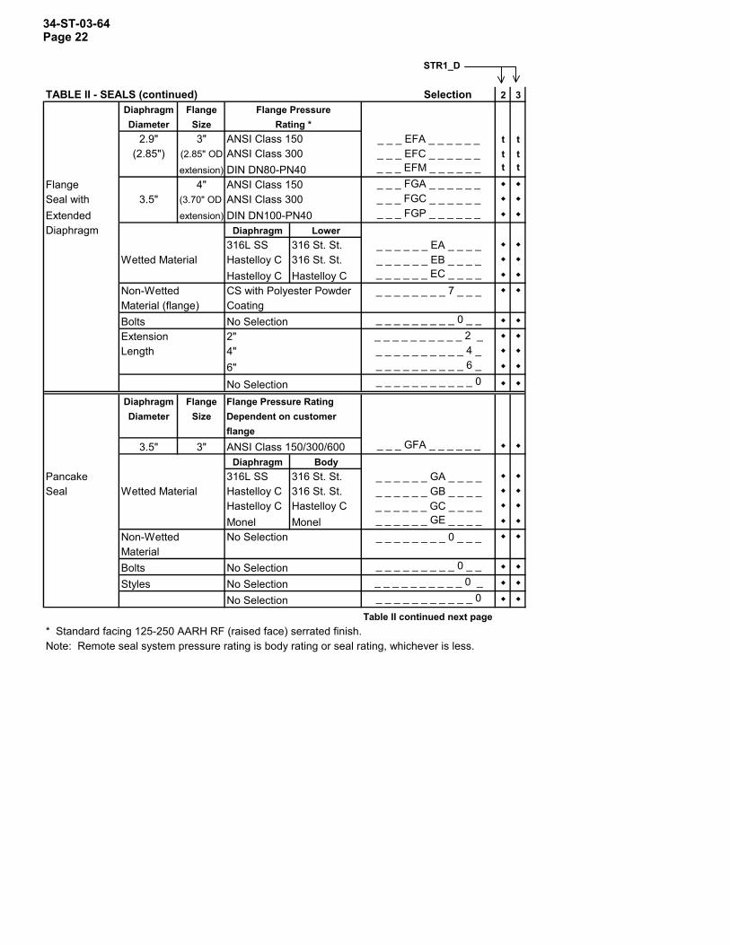
34-ST-03-64 Page 22
STR1_D
TABLE II - SEALS (continued) Selection 2 3Diaphragm Flange Flange PressureDiameter Size Rating *
2.9" 3" ANSI Class 150 _ _ _ EFA _ _ _ _ _ _ t t(2.85") (2.85" OD ANSI Class 300 _ _ _ EFC _ _ _ _ _ _ t t
extension) DIN DN80-PN40 _ _ _ EFM _ _ _ _ _ _ t t
Flange 4" ANSI Class 150 _ _ _ FGA _ _ _ _ _ _Seal with 3.5" (3.70" OD ANSI Class 300 _ _ _ FGC _ _ _ _ _ _Extended extension) DIN DN100-PN40 _ _ _ FGP _ _ _ _ _ _Diaphragm Diaphragm Lower
316L SS 316 St. St. _ _ _ _ _ _ EA _ _ _ _Wetted Material Hastelloy C 316 St. St. _ _ _ _ _ _ EB _ _ _ _
Hastelloy C Hastelloy C _ _ _ _ _ _ EC _ _ _ _Non-Wetted CS with Polyester Powder _ _ _ _ _ _ _ _ 7 _ _ _Material (flange) CoatingBolts No Selection _ _ _ _ _ _ _ _ _ 0 _ _Extension 2" _ _ _ _ _ _ _ _ _ _ 2 _Length 4" _ _ _ _ _ _ _ _ _ _ 4 _
6" _ _ _ _ _ _ _ _ _ _ 6 _
No Selection _ _ _ _ _ _ _ _ _ _ _ 0
Diaphragm Flange Flange Pressure RatingDiameter Size Dependent on customer
flange3.5" 3" ANSI Class 150/300/600 _ _ _ GFA _ _ _ _ _ _
Diaphragm BodyPancake 316L SS 316 St. St. _ _ _ _ _ _ GA _ _ _ _Seal Wetted Material Hastelloy C 316 St. St. _ _ _ _ _ _ GB _ _ _ _
Hastelloy C Hastelloy C _ _ _ _ _ _ GC _ _ _ _Monel Monel _ _ _ _ _ _ GE _ _ _ _
Non-Wetted No Selection _ _ _ _ _ _ _ _ 0 _ _ _MaterialBolts No Selection _ _ _ _ _ _ _ _ _ 0 _ _
Styles No Selection _ _ _ _ _ _ _ _ _ _ 0 _
No Selection _ _ _ _ _ _ _ _ _ _ _ 0
Table II continued next page* Standard facing 125-250 AARH RF (raised face) serrated finish.Note: Remote seal system pressure rating is body rating or seal rating, whichever is less.
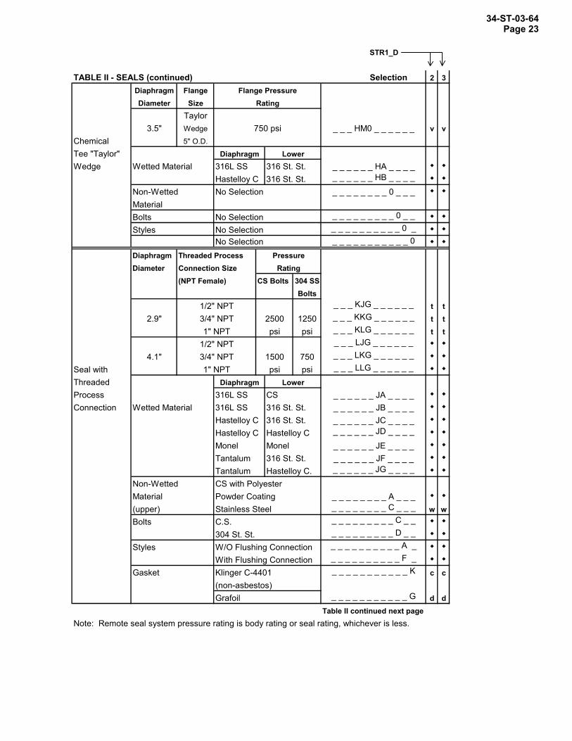
34-ST-03-64 Page 23
STR1_D
TABLE II - SEALS (continued) Selection 2 3Diaphragm Flange Flange PressureDiameter Size Rating
Taylor3.5" Wedge 750 psi _ _ _ HM0 _ _ _ _ _ _ v v
Chemical 5" O.D.Tee "Taylor" Diaphragm LowerWedge Wetted Material 316L SS 316 St. St. _ _ _ _ _ _ HA _ _ _ _
Hastelloy C 316 St. St. _ _ _ _ _ _ HB _ _ _ _
Non-Wetted No Selection _ _ _ _ _ _ _ _ 0 _ _ _MaterialBolts No Selection _ _ _ _ _ _ _ _ _ 0 _ _
Styles No Selection _ _ _ _ _ _ _ _ _ _ 0 _No Selection _ _ _ _ _ _ _ _ _ _ _ 0
Diaphragm Threaded Process PressureDiameter Connection Size Rating
(NPT Female) CS Bolts 304 SSBolts
1/2" NPT _ _ _ KJG _ _ _ _ _ _ t t2.9" 3/4" NPT 2500 1250 _ _ _ KKG _ _ _ _ _ _ t t
1" NPT psi psi _ _ _ KLG _ _ _ _ _ _ t t1/2" NPT _ _ _ LJG _ _ _ _ _ _
4.1" 3/4" NPT 1500 750 _ _ _ LKG _ _ _ _ _ _
Seal with 1" NPT psi psi _ _ _ LLG _ _ _ _ _ _
Threaded Diaphragm LowerProcess 316L SS CS _ _ _ _ _ _ JA _ _ _ _Connection Wetted Material 316L SS 316 St. St. _ _ _ _ _ _ JB _ _ _ _
Hastelloy C 316 St. St. _ _ _ _ _ _ JC _ _ _ _Hastelloy C Hastelloy C _ _ _ _ _ _ JD _ _ _ _
Monel Monel _ _ _ _ _ _ JE _ _ _ _Tantalum 316 St. St. _ _ _ _ _ _ JF _ _ _ _Tantalum Hastelloy C. _ _ _ _ _ _ JG _ _ _ _
Non-Wetted CS with PolyesterMaterial Powder Coating _ _ _ _ _ _ _ _ A _ _ _(upper) Stainless Steel _ _ _ _ _ _ _ _ C _ _ _ w wBolts C.S. _ _ _ _ _ _ _ _ _ C _ _
304 St. St. _ _ _ _ _ _ _ _ _ D _ _
Styles W/O Flushing Connection _ _ _ _ _ _ _ _ _ _ A _
With Flushing Connection _ _ _ _ _ _ _ _ _ _ F _
Gasket Klinger C-4401 _ _ _ _ _ _ _ _ _ _ _ K c c(non-asbestos)Grafoil _ _ _ _ _ _ _ _ _ _ _ G d d
Table II continued next pageNote: Remote seal system pressure rating is body rating or seal rating, whichever is less.

34-ST-03-64 Page 24
STR1_D
TABLE II - SEALS (continued) Selection 2 3Diaphragm Flange Pressure RatingDiameter Size
2.9" 3" Customer clamp rating or _ _ _ PF0 _ _ _ _ _ _ t t4.1" 4" 600 psi, whichever is less _ _ _ QG0 _ _ _ _ _ _
Sanitary Diaphragm BodySeal Wetted Material 316L SS 316 St. St. _ _ _ _ _ _ N A _ _ _ _
Non-Wetted No Selection _ _ _ _ _ _ _ _ 0 _ _ _MaterialBolts No Selection _ _ _ _ _ _ _ _ _ 0 _ _
Styles Tri-Clover Tri-Clamp _ _ _ _ _ _ _ _ _ _ 8 _
Gasket No Selection _ _ _ _ _ _ _ _ _ _ _ 0
Note: All sanitary seals have dairy grade 3A approval.Note: Remote seal system pressure rating is body rating or seal rating, whichever is less.TABLE III - OPTIONSNone 00FOUNDATION Fieldbus Communications FF r rHART Protocol compatible electronics HC e eAnalog Meter (0-100 Even 0-10 Square Root) MESmart Meter SMCustomer Configuration of Smart Meter CI f fLocal Zero & Span ZS m mLocal Zero LZ x xLightning Protection LPCustom Calibration and I.D. in Memory CCTransmitter Configuration - non-Fieldbus TCWrite Protection WPEnd Cap Live Circuit Warning Label in Spanish (only with ATEX 3D) a aEnd Cap Live Circuit Warning Label in Portuguese (only with ATEX 3D) a a bEnd Cap Live Circuit Warning Label in Italian (only with ATEX 3D) a aEnd Cap Live Circuit Warning Label in German (only with ATEX 3D) a aA286SS (NACE) Bolts and 302/304SS (NACE) Nuts for Heads CRStainless Steel Customer Wired-On Tag TG (4 lines, 28 characters per line, customer supplied information)Stainless Steel Customer Wired-On Tag (blank) TBMounting Bracket - Carbon Steel MBMounting Bracket - ST. ST. SB bFlat Mounting Bracket FB316 ST.ST. Electronics Housing - with M20 Conduit Connections SH n n1/2" NPT to M20 316SS Conduit Adapter (BASEEFA EEx d IIC) A1 n n1/2" NPT to 3/4" NPT 316 SS Conduit Adapter A2 u uStainless Steel Housing with M20 to 1/2" NPT 316 SS Conduit A3 i i Adapter (use for FM and CSA Approvals)Clean Transmitter for Oxygen or Chlorine Service with Certificate 0X h hMarine Type Approvals (DNV, ABS, BV & LR) MT 2 2Over-Pressure Leak Test with F3392 Certificate TPCalibration Test Report and Certificate of Conformance (F3399) F1Certificate of Conformance (F3391) F3Certificate of Origin (F0195) F5FMEDA (SIL) Certificate F6NACE Certificate (F0198) F7 o oAdditional Warranty - 1 year W1Additional Warranty - 2 years W2Additional Warranty - 3 years W3Additional Warranty - 4 years
SPPGTLGE
W4
b
b
b
b
b
b

34-ST-03-64 Page 25
STR1_D
TABLE III - OPTIONS (continued) Selection 2 3Approval
Body Approval Type Location or Classification No hazardous location approvals 9X
Explosion Proof Class I, Div. 1, Groups A,B,C,DFactory Dust Ignition Proof Class II, III Div. 1, Groups E,F,GMutual Non-Incendive Class I, Div. 2, Groups A,B,C,D 1C
Intrinsically Safe Class I, II, III, Div. 1, GroupsA,B,C,D,E,F,G
Explosion Proof Class I, Div. 1, Groups B,C,DCSA Dust Ignition Proof Class II, III, Div. 1, Groups E,F,G 2J
Intrinsically Safe Class I, II, III, Div. 1, GroupsA,B,C,D,E,F,G b
SA Intrinsically Safe Ex ia IIC T4 4G(Australia) Non-Sparking Ex n IIC T6 (T4 with SM option)
Intrinsically Safe, Zone Ex II 1G EEx ia IIC T4, T5,T6 3S0/1 Flameproof, Zone 1 Ex II 2G EEx d IIC T5, T6, 3D
ATEX* Enclosure IP 66/67Non-Sparking, Zone 2 Ex II 3G EEx nA, IIC T6 3N
(Honeywell). Enclosure IP 66/67Multiple Marking** Ex II 1 G EEx ia IIC T4, T5, T6Int. Safe, Zone 0/1, or Ex II 2 G EEx d IIC T5, T6 3HFlameproof, Zone 1, or Ex II 3 G EEx nA, IIC T6 (Honeywell) Non-Sparking, Zone 2 Enclosure IP 66/67
INMETRO Flameproof, Zone 1 Ex d IIC T5 6D(Brazil)
*See ATEX installation requirements in the ST 3000 User's Manual
TABLE IVFactory Identification XXXX
**The user must determine the type of protection required for installation of the equipment. The user shall then check the box [a] adjacent to the type of protection used on the equipment certification nameplate. Once a type of protection has been checked on the nameplate, the equipment shall not then be reinstalled using any of the other certification types.

34-ST-03-64 Page 26
RESTRICTIONSRestriction Available Only With Not Available With
Letter Table Selection Table SelectionIII
b Select only one option from this groupc II _ _ _ _ _ _ BF _ _ _ _,
_ _ _ _ _ _ BG _ _ _ _,_ _ _ _ _ _ JF _ _ _ _,_ _ _ _ _ _ JG _ _ _ _,
d II _ _ _ _ _ _ BF _ _ _ _,_ _ _ _ _ _ BG _ _ _ _,_ _ _ _ _ _ JF _ _ _ _,_ _ _ _ _ _ JG _ _ _ _,
e III 4Gf III SMh I, II _ 2 _ - 2 _ _ _ _ _ _ _ _ _ _ _
i III 1C or 2J
m III ME, FFn III 1C, 2Jo III CRp II DC704 and Syltherm 800
fills and close-couple requireSS seal upper.
_ _ _ CAA _ _ 5 _ _ _,_ _ _ CCA _ _ 5 _ _ _,_ _ _ CCC _ _ 5 _ _ _,_ _ _ DAA _ _ 5 _ _ _,_ _ _ DCA _ _ 5 _ _ _,_ _ _ DCC _ _ 5 _ _ _,_ _ _ DGA _ _ 5 _ _ _,_ _ _ DGC _ _ 5 _ _ _,_ _ _ DDA _ _ 5 _ _ _,_ _ _ _ _ _ GE _ _ _ _,_ _ _ _ _ _ _ _ A _ _ _
q II 2 _ _ _ _ _ _ _ _ _ _ _ _,4 _ _ _ _ _ _ _ _ _ _ _ _
r III TC, ME, 4G, 3Ss Must be specified with Model STR12Dt I 2 _ _
II _ B _ _ _ _ _ _ _ _ _ _,_ C _ _ _ _ _ _ _ _ _ _,_ D _ _ _ _ _ _ _ _ _ _,_ E _ _ _ _ _ _ _ _ _ _,_ F _ _ _ _ _ _ _ _ _ _,_ H _ _ _ _ _ _ _ _ _ _,_ J _ _ _ _ _ _ _ _ _ _,_ K _ _ _ _ _ _ _ _ _ _,_ L _ _ _ _ _ _ _ _ _ _,_ M _ _ _ _ _ _ _ _ _ _
a 3D or 3H

34-ST-03-64 Page 27 RESTRICTIONS Continued
u III 1C, 2Jw II _ _ _ _ _ _ JA _ _ _ _x III FF, SMy I 1 _ _, 3 _ _ III MB, SB, FB
II _ 2 _ _ _ _ _ _ _ _ _ _ II DC704 and Syltherm 800fills and close-couple requireSS seal upper.
_ _ _ CAA _ _ 5 _ _ _,_ _ _ CCA _ _ 5 _ _ _,_ _ _ CCC _ _ 5 _ _ _,_ _ _ DAA _ _ 5 _ _ _,_ _ _ DCA _ _ 5 _ _ _,_ _ _ DCC _ _ 5 _ _ _,_ _ _ DGA _ _ 5 _ _ _,_ _ _ DGC _ _ 5 _ _ _,_ _ _ DDA _ _ 5 _ _ _,_ _ _ _ _ _ GE _ _ _ _,_ _ _ _ _ _ _ _ A _ _ _
z I _ _ D
2 III FB
Note: See ST-83 for Published Specials with pricing.See ST-89 and User's Manual for part numbers.See ST-OE-9 for OMS Order Entry Information including TC, manuals, certificates,
drawings and SPINS.See ST-OD-1 for tagging, ID, Transmitter Configuration (TC) and calibration including
factory default values.To request a quote for a non-published "special", fax RFQ w/ Application Data Sht
(34-ST-18-01) to Mktg. Applications.See Specification 34-ST-03-64 for Seal dimensions.
34-ST-03-64 Page 28
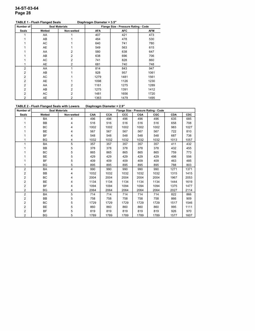
TABLE 1 - Flush Flanged Seals Diaphragm Diameter = 3.5"Number of Seal Materials Flange Size - Pressure Rating - Code
Seals Wetted Non-wetted AFA AFC AFM1 AA 1 407 421 4731 AB 1 464 478 5301 AC 1 640 741 7801 AE 1 549 563 6151 AA 2 580 638 6471 AB 2 638 696 7061 AC 2 741 828 8601 AE 2 681 740 7482 AA 1 814 843 9472 AB 1 928 957 10612 AC 1 1279 1481 15612 AE 1 1098 1126 12302 AA 2 1161 1275 12892 AB 2 1275 1391 14122 AC 2 1481 1656 17202 AE 2 1363 1479 1495
TABLE 2 - Flush Flanged Seals with Lowers Diaphragm Diameter = 2.9"Number of Seal Materials Flange Size - Pressure Rating - Code
Seals Wetted Non-wetted CAA CCA CCC CGA CGC CDA CDC1 BA 4 496 496 496 496 496 635 6851 BB 4 516 516 516 516 516 658 7081 BC 4 1002 1002 1002 1002 1002 983 10271 BE 4 567 567 567 567 567 722 8101 BF 4 548 548 548 548 548 687 7381 BG 4 1032 1032 1032 1032 1032 1013 10571 BA 5 357 357 357 357 357 411 4321 BB 5 378 378 378 378 378 432 4551 BC 5 865 865 865 865 865 759 7731 BE 5 429 429 429 429 429 498 5561 BF 5 409 409 409 409 409 463 4851 BG 5 895 895 895 895 895 788 8032 BA 4 990 990 990 990 990 1271 13712 BB 4 1032 1032 1032 1032 1032 1315 14152 BC 4 2004 2004 2004 2004 2004 1967 20532 BE 4 1134 1134 1134 1134 1134 1444 16192 BF 4 1094 1094 1094 1094 1094 1375 14772 BG 4 2064 2064 2064 2064 2064 2027 21142 BA 5 714 714 714 714 714 822 8662 BB 5 758 758 758 758 758 866 9092 BC 5 1729 1729 1729 1729 1729 1517 15462 BE 5 860 860 860 860 860 995 11112 BF 5 819 819 819 819 819 926 9702 BG 5 1789 1789 1789 1789 1789 1577 1607

34-ST-03-64 Page 29 TABLE 3 - Flush Flanged Seals with Lowers Diaphragm Diameter = 4.1"Number of Seal Materials Flange Size - Pressure Rating - Code
Seals Wetted Non-wetted DAA DCA DCC DGA DGC DDA DDC DFA DFC1 BA 4 748 748 770 748 770 685 599 881 10821 BB 4 814 814 835 814 835 751 853 947 11461 BC 4 1379 1379 1429 1379 1429 1280 1294 1490 16691 BE 4 891 891 979 891 979 866 968 1047 12461 BF 4 857 857 879 857 879 795 896 990 11901 BG 4 1422 1422 1473 1422 1473 1323 1338 1533 17121 BA 5 596 596 618 596 618 533 533 577 6551 BB 5 662 662 683 662 683 600 600 643 7191 BC 5 1227 1227 1278 1227 1278 1128 1041 1186 12411 BE 5 740 740 826 740 826 714 714 743 8201 BF 5 706 706 727 706 727 643 643 685 7631 BG 5 1270 1270 1320 1270 1320 1172 1084 1094 12852 BA 4 1496 1496 1540 1496 1540 1371 1575 1763 21642 BB 4 1627 1627 1671 1627 1671 1502 1706 1893 22932 BC 4 2757 2757 2859 2757 2859 2559 2589 2979 33372 BE 4 1783 1783 1958 1783 1958 1731 1935 2093 24932 BF 4 1715 1715 1758 1715 1758 1590 1791 1961 23812 BG 4 2845 2845 2947 2845 2947 2647 2675 3067 34232 BA 5 1192 1192 1236 1192 1236 1068 1068 1155 13092 BB 5 1323 1323 1367 1323 1367 1199 1199 1286 14382 BC 5 2641 2641 2555 2641 2555 2255 2255 2373 24812 BE 5 1479 1479 1652 1479 1652 1427 1427 1486 16402 BF 5 1411 1411 1455 1411 1455 1286 1286 1371 15252 BG 5 2541 2541 2641 2541 2641 2343 2343 2459 2569
TABLE 4 - Price Add for Flush Flanged Seals with Lowers and Flushing Connection: Code = 7Seal Materials Flange Size - Pressure Rating - Code
Number of Diaph. Dia. = 2.9" Diaph. Dia. = 4.1"Seals Wetted CAA, CCA, CCC, CGA, DAA, DCA, DCC, DGA,
CGA, CDA, CDC DGC, DDA, DDC,DFA, DFC
1 BA 44 1151 BB 44 1151 BC 138 1591 BE 131 1451 BF 44 1151 BG 138 1592 BA 88 2312 BB 88 2312 BC 274 3182 BE 260 2902 BF 88 2312 BG 274 318
34-ST-03-64 Page 30
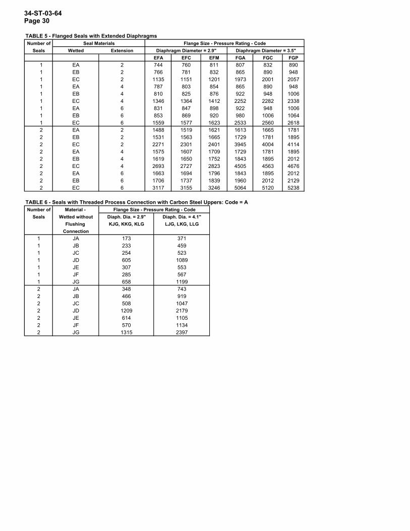
TABLE 5 - Flanged Seals with Extended DiaphragmsNumber of Seal Materials Flange Size - Pressure Rating - Code
Seals Wetted Extension Diaphragm Diameter = 2.9" Diaphragm Diameter = 3.5"EFA EFC EFM FGA FGC FGP
1 EA 2 744 760 811 807 832 8901 EB 2 766 781 832 865 890 9481 EC 2 1135 1151 1201 1973 2001 20571 EA 4 787 803 854 865 890 9481 EB 4 810 825 876 922 948 10061 EC 4 1346 1364 1412 2252 2282 23381 EA 6 831 847 898 922 948 10061 EB 6 853 869 920 980 1006 10641 EC 6 1559 1577 1623 2533 2560 26182 EA 2 1488 1519 1621 1613 1665 17812 EB 2 1531 1563 1665 1729 1781 18952 EC 2 2271 2301 2401 3945 4004 41142 EA 4 1575 1607 1709 1729 1781 18952 EB 4 1619 1650 1752 1843 1895 20122 EC 4 2693 2727 2823 4505 4563 46762 EA 6 1663 1694 1796 1843 1895 20122 EB 6 1706 1737 1839 1960 2012 21292 EC 6 3117 3155 3246 5064 5120 5238
TABLE 6 - Seals with Threaded Process Connection with Carbon Steel Uppers: Code = ANumber of Material - Flange Size - Pressure Rating - Code
Seals Wetted without Diaph. Dia. = 2.9" Diaph. Dia. = 4.1"Flushing KJG, KKG, KLG LJG, LKG, LLG
Connection1 JA 173 3711 JB 233 4591 JC 254 5231 JD 605 10891 JE 307 5531 JF 285 5671 JG 658 11992 JA 348 7432 JB 466 9192 JC 508 10472 JD 1209 21792 JE 614 11052 JF 570 11342 JG 1315 2397
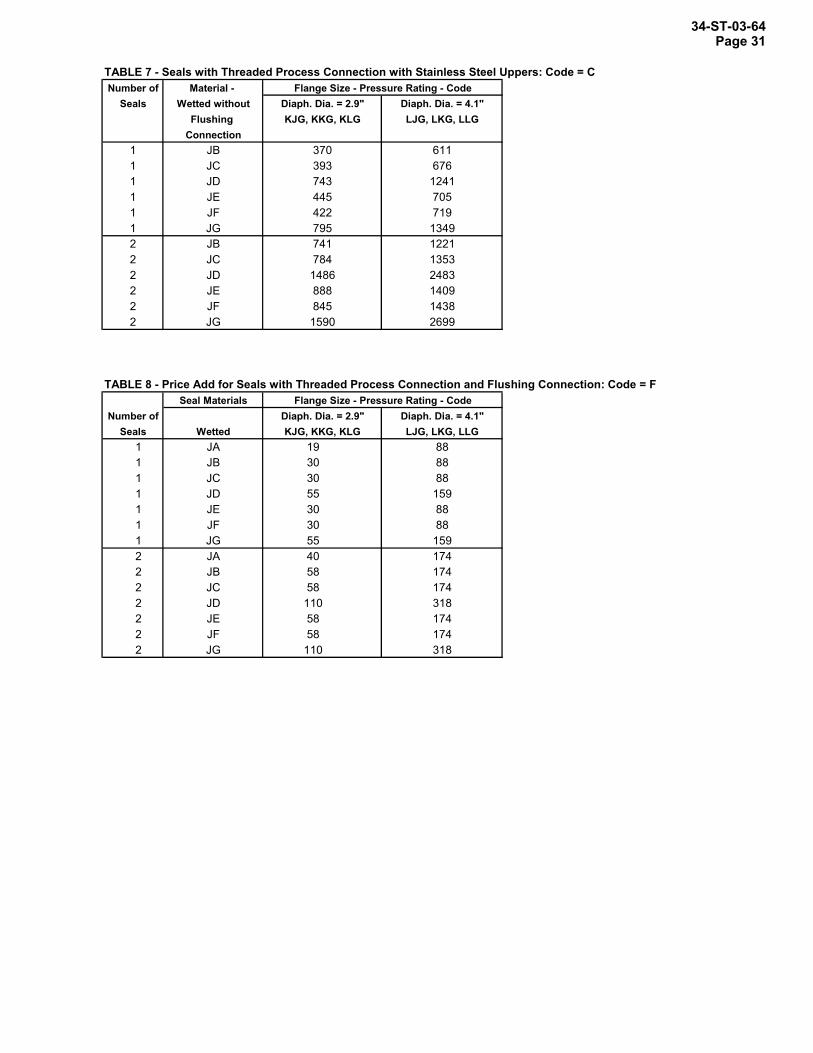
34-ST-03-64 Page 31 TABLE 7 - Seals with Threaded Process Connection with Stainless Steel Uppers: Code = CNumber of Material - Flange Size - Pressure Rating - Code
Seals Wetted without Diaph. Dia. = 2.9" Diaph. Dia. = 4.1"Flushing KJG, KKG, KLG LJG, LKG, LLG
Connection1 JB 370 6111 JC 393 6761 JD 743 12411 JE 445 7051 JF 422 7191 JG 795 13492 JB 741 12212 JC 784 13532 JD 1486 24832 JE 888 14092 JF 845 14382 JG 1590 2699
TABLE 8 - Price Add for Seals with Threaded Process Connection and Flushing Connection: Code = FSeal Materials Flange Size - Pressure Rating - Code
Number of Diaph. Dia. = 2.9" Diaph. Dia. = 4.1"Seals Wetted KJG, KKG, KLG LJG, LKG, LLG
1 JA 19 881 JB 30 881 JC 30 881 JD 55 1591 JE 30 881 JF 30 881 JG 55 1592 JA 40 1742 JB 58 1742 JC 58 1742 JD 110 3182 JE 58 1742 JF 58 1742 JG 110 318

34-ST-03-64 Page 32
Wetted Materials
Diaphragm
Upper Insert
Dimension 3.5” Diaphragm
Dia. (in.)
Type Size Non-wetted
Material
Construction
See Figure A B
CS
316 LSS Hast C Hast C Monel Monel
SS SS
Hast C SS
Monel
10a
7.50
1.10
3” 150
SS
316 LSS Hast C Monel
N/A
10b 10a 10b
0.94 1.10 0.94
CS
316 LSS Hast C Hast C Monel Monel
SS SS
Hast C SS
Monel
10a
8.25
1.31
3” 300
SS
316 LSS Hast C Monel
N/A
10b 10a 10b
1.12 1.31 1.12
CS
316 LSS Hast C Hast C Monel Monel
SS SS
Hast C SS
Monel
10a
7.87
1.07
Flush Flanged
Seal
DIN DN80-PN40
SS
316 LSS Hast C Monel
N/A
10b 10a 10b
0.94 1.07 0.94
Upper (Non-Wetted)
Upper Insert (Wetted)
Figure 10a. Flush Flanged Seal
Instrument Connection
Diaphragm (Wetted)
A
B1.7"
20395
Upper (Non-wetted)
Figure 10b. Flush Flanged Seal
Instrument Connection
Diaphragm (Wetted)
A
22839
B
34-ST-03-64 Page 33
Model Selection Guide, cont.
Figure 12. Flush Flanged Seal with Lower ( )
Figure 11. Flush Flanged Seal with Lower (■ )
FlushFlangedSealwithLower
150
Type Size Dim.2.9"
Diaph.Dia. (in.)
4.1"Diaph.
Dia. (in.)
1/2"ABC
4.00 1.90—
5.30 2.10—
1"ABC
4.00 2.00—
5.30 2.10—
1-1/2"ABC
■ 5.00■ 1.80■ 1.20
5.30 2.10—
2"ABC
■ 6.00■ 1.80■ 1.30
5.80 2.00—
3"ABC
■ 7.50■ 2.30■ 1.90
■ 7.50■ 2.00■ 1.60
300
1"ABC
4.50 2.10—
5.30 2.10—
1-1/2"ABC
■ 6.10■ 1.80■ 1.30
5.80 2.30—
2"ABC
■ 6.50■ 1.80■ 1.40
■ 6.50■ 2.30■ 1.90
3"ABC
■ 8.30■ 2.40■ 1.80
■ 8.30■ 2.30■ 2.10
2.4"Diaph.
Dia. (in.)
3.50 2.00—
■ 4.00■ 1.70■ 1.10
■ 5.00■ 1.80■ 1.20
■ 6.00■ 1.90■ 1.40
■ 7.50■ 2.30■ 1.90
■ 4.90■ 1.90■ 1.30
■ 6.10■ 1.80■ 1.20
■ 6.50■ 1.90■ 1.50
■ 8.30■ 2.70■ 2.10
Upper(Non-Wetted)
Lower(Wetted)
Upper Insert(Non-Wetted)
InstrumentConnection
Gasket(Wetted)
Diaphragm(Wetted)
A
BC
20396
Upper(Non-Wetted)
Lower(Wetted)
InstrumentConnection
GasketDiaphragm(Wetted)
Bolt*
User SuppliedFlange and Nut
Stud
A
B
*Bolts and Upper are same material. 20397

34-ST-03-64 Page 34
Model Selection Guide, cont.
Figure 13. Flanged Seal with Extended Diaphragm
Flange (Non-Wetted)
Extension (Wetted) Diaphragm
(Wetted)
Instrument Connection
Raised Face (Wetted)
Extension Length
A
B
20398C
Figure 14. Pancake Seal
Body (Wetted) Diaphragm
(Wetted)
Instrument Connection
User Supplied Flange and Bolt (3/8 -24 NF threads)
B
A
20399
Figure 15. Chemical Tee "Taylor Wedge"
Body (Wetted) Instrument
Connection
Diaphragm (Wetted)
B
A
20400
Flanged Seal with Extended Diaphgram
DIN DN80- PN40
Type Size Dim.2.9"
Diaph. Dia. (in.)
A B C*
— — —
A B C*
— — —
A B C*
— — —
A B C*
9.00 0.94 3.70
A B C*
10.00 1.25 3.70
A B C*
9.25 0.94 3.70
2.4" Diaph.
Dia. (in.)
7.50 0.94 2.85
8.25 1.12 2.85
7.87 0.94 2.85
— — —
— — —
— — —
3" 150
3" 300
4" 150
4" 300
DIN DN100- PN40
Type Size Dimension 3.5" Diaph. Dia. (in.)
Pancake Seal
A B
5.00 0.90
3" 150/300/600
Type Size Dimension 3.5" Diaph. Dia. (in.)
Chemical Tee "Taylor Wedge" Seal
A B
5.00 0.50750 psi
*Designed to mate with Sch 40 pipe.
34-ST-03-64 Page 35
Model Selection Guide, cont.
Figure 17. Sanitary Seal
Instrument Connection
Body (Wetted)
Diaphragm (Wetted)
B
A 20402
Figure 16. Seal with Threaded Process Connection
Upper (Non-Wetted)
Lower (Wetted)
Gasket Wetted
Bolt
Instrument Connection
Diaphragm (Wetted)
B
A
20401
Seal with Threaded Process Connection
Type Size Dim.2.9"
Diaph. Dia. (in.)
4.1" Diaph.
Dia. (in.)
1/4" or
1/2"
A B
4.00 1.80
5.30 1.80
A B
4.00 2.10
5.30 2.10
2.4" Diaph.
Dia. (in.)
3.50 1.80
3.50 2.10
3/4" or 1"
Sanitary Seal
Type Size Dim.2.4"
Diaph. Dia. (in.)
2.9" Diaph.
Dia. (in.)
2" A B
— —
— —
A B
3.00 1.20
— —
1.9" Diaph.
Dia. (in.)
2.50 1.20
— —2-1/2"
4.1" Diaph.
Dia. (in.)
— —
— —
A B
— —
3.60 1.20
— —3" —
—
A B
— —
— —
— —4" 4.7
1.0

34-ST-03-64 Page 36
Model Selection Guide, cont.
Figure 18. 3" Saddle Seal
Bolts Body (Non-Wetted)
Lower Housing (Wetted)
Instrument Connection
Diaphragm (Wetted)
Weld by User Gasket
(Wetted)
A
B
20403
Weld by User
Bolt
Instrument Connection
Gasket (Wetted)
Diaphragm (Wetted)
Lower Housing (Wetted)
Body (Non-Wetted)
Figure 19. 4" or larger Saddle Seal
B
A
20404
Type Size Dimension 2.4" Diaph. Dia. (in.)
Saddle Seal
A B
3.50 2.303"
A B
3.50 2.40
4" or larger
ST 3000 is a registered trademark of Honeywell International Inc. HART* is a trademark of the Hart Communication Foundation. FOUNDATION™ is a trademark of the Fieldbus Foundation.
Industrial Measurement and Control Honeywell International Inc. 2500 W. Union Hill Drive Phoenix, Arizona 85027 Honeywell International Inc.