transmutation of americium in fast neutron facilities
TRANSCRIPT

Transmutation of Americium in Fast Neutron
Facilities
YOUPENG ZHANG
Licentiate Thesis, Stockholm, Sweden, 2011
TRITA-FYS 2011:07

iii
Abstract
In this thesis, the feasibility to use a medium sized sodium cooled fast re-actor fully loaded with MOX fuel for efficient transmutation of americium isinvestigated by simulating the safety performance of a BN600-type fast reac-tor loaded with different fractions of americium in the fuel, using the safetyparameters obtained with the SERPENT Monte Carlo code. The focus ison americium mainly due to its long-term contribution to the radiotoxicity ofspent nuclear fuel and its deterioration on core’s safety parameters. Apply-ing the SAS4A/SASSYS transient analysis code, it is demonstrated that thepower rating needs to be reduced by 6% for each percent additional americiumintroduction into the reference MOX fuel, maintaining 100 K margin to fuelmelting, which is the most limiting failure mechanism.
Safety analysis of a new Accelerator Driven System design with a smallerpin pitch-to-diameter ratio comparing to the reference EFIT-400 design, aim-ing at improving neutron source efficiency, was also performed by simulat-ing performance for unprotected loss of flow, unprotected transient overpower,and protected loss-of-heat-sink transients, using neutronic parameters obatinedfrom MCNP calculations. Thanks to the introduction of the austenitic 15/15Tistainless steel with enhanced creep rupture resistance and acceptable irradia-tion swelling rate, the suggested ADS design loaded with nitride fuel and cooledby lead-bismuth eutectic could survive the full set of transients, preserving amargin of 130 K to cladding rupture during the most limiting transient.
The thesis concludes that efficient transmutation of americium in a mediumsized sodium cooled fast reactor loaded with MOX fuel is possible but leadsto a severe power penalty. Instead, preserving transmutation rates of minoractinides up to 42 kg/TWhth, the suggested ADS design with enhanced protonsource efficiency appears like a better option for americium transmutation.


Acknowledgements
First of all, I want to express my sincerest appreciation to my supervisor, Prof.Janne Wallenius, who has supported me throughout my licentiate thesis with hispatience and knowledge. I attribute to his encouragements and efforts on this thesis’writing procedure.
In my daily work I have been blessed with my friendly colleagues: Calle andAndrei as my old roomates sharing wonderful talks and discussions on both physicsand life tips; Dr. Michael Jolkkonen as an encyclopedia-type consultant for almosteverything; Dr. Nils Sandberg for excellent comments on influences of irradiationdamage and also as the best ski instructor; Dr. Vasily Arzhanov for cooperationsduring the lab teaching and also instructive stories; Dr. Torbjörn Bäck for excellentinstructions on lab teaching and Linux usage.
I also want to express my gratitude to Dr. Daniel Westlén and Dr. MarcusEriksson who aroused my passion on reactor physics before I started my PhD careerthree years ago.
To Odd Runevall and Jan Dufek, thanks for your comments on my first journalpaper, which is really an important milestone.
To Sideeg, thanks for helping me to sketch out SERPENT models.I want to thank the wonderful working circumstance created by Milan, Jitka,
Pertti, Han Song, Merja, Farnaz, Qi Chong and Xu Zhenxiang.This research was financially supported by Svensk Kärnbränslehantering AB
(SKB).The Department of Physics has provided the support and equipment I have
needed to accomplish my studies.Finally, I want to show my thanks to my parents for encouraging on my PhD
study and also my girlfriend for taking care of my life in Sweden.
v


List of Papers
Publications
1. Youpeng Zhang, Janne Wallenius and Andrei Fokau, Transmutation of Ameri-cium in a Medium Size Sodium Cooled Fast Reactor Design, Annals of NuclearEnergy, 37(5):629-638, 2010.
2. Youpeng Zhang, Andrei Fokau, Shinya Ishida and Janne Wallenius, Physicsand safety studies of a compact ADS design loaded with nitride fuel, Annalsof Nuclear Energy, Submitted, 2010.
Author’s Contribution
In Paper I and II, reactor performance parameters and reactivity coefficientswere calculated with the SERPENT Monte Carlo code by the author. In addi-tion, the core safety performance for various transients were simulated with theSAS4A/SASSYS code by the author.
Papers Not Included
1. Andrei Fokau, Youpeng Zhang, Shinya Ishida, Janne Wallenius, A source effi-cient ADS for minor actinides burning, Annals of Nuclear Energy, 37(4):540-545, 2010.
2. W. Maschek, C. Artioli, X. Chen, F. Delage, A. Fernandez-Carretero, M.Flad, A. Fokau, F. Gabrielli, G. Glinatsis, P. Liu, L. Mansani, C. MatzerathBoccaccini, C. Petrovich, A. Rineiski, M. Sarotto, M. Schikorr, V. Sobolev,S. Wang, Y. Zhang, Design, Safety and Fuel Developments for the EFIT Ac-celerator Driven System with CERCER and CERMET Cores, Actinide andFission Product Partitioning and Transmutation, 10th OECD/NEA Informa-tion Exchange Meeting, Mito, Japan, 2008.
3. Youpeng Zhang and Janne Wallenius, Upper Limits to Americium Concentra-tion in Medium Size Sodium Cooled Fast Reactors, Global 2009, Paris, France,2009.
vii


ix

x NOMENCLATURE
Nomenclature
ADS Accelerator Driven System
BOC Beginning of Cycle
CW Cold Worked, a work hardening process to enhance metal’smechanical properties
DHR Decay Heat Removal
EBR-II SHRT Shutdown Heat Removal Test on Experimental BreederReactor, metallic fuel loaded and sodium cooled
EFIT European Facility for IndustrialTransmutation
EOC End of Cycle
EOEC End of Equilibrium Cycle
FBR Fast Breeder Reactor, conversion ratio higher than 1.0
FIMA Fission of Initial Metal Atom
FP Fission Products
GEMs Gas Expansion Modules
GeV Giga electron Volts
GFR Gas-cooled Fast Reactor
HLM Heavy Liquid Metal
HLW High Level Waste
HTR High Temperature gas-cooled Reactor
xi
LBE Lead-bismuth Eutectic
LFR Liquid-metal-cooled Fast Reactor
LINAC LINear ACcelerator
LLW Low Level Waste
MA Minor Actinides, actinides except U and Pu , e.g., NpAm, Cm
MeV Mega electron Volts
MLW Medium Level Waste
MOX Mixed OXide, a compound of PuO2 and UO2
MWe Megawatt electrical
MWth Megawatt thermal
PDS-XADS Preliminary Design Studies of an ExperimentalAccelerator Driven System
PLOHS Protected Loss-of-Heat-Sink
ULOF Unprotected Loss-of-Flow
UTOP Unprotected Transient-over-Power
RF Radio Frequency
SFR Sodium-cooled Fast Reactor
TREAT M-series Transient REActor Test facility, seriestests for Metallic fuel in Mark-III sodium loop
UOX Uranium OXide
XTADS eXperimental facility demonstratingthe technical feasibility of Transmutation in anAccelerator Driven System
Contents
Acknowledgements v
List of Papers vii
Publications . . . . . . . . . . . . . . . . . . . . . . . . . . . . . . . . . . . vii
Author’s Contribution . . . . . . . . . . . . . . . . . . . . . . . . . . . . . vii
Papers Not Included . . . . . . . . . . . . . . . . . . . . . . . . . . . . . . vii
Nomenclature x
Contents xii
1 Introduction 1
1.1 Nuclear waste . . . . . . . . . . . . . . . . . . . . . . . . . . . . . . . 1
1.2 Transmutation . . . . . . . . . . . . . . . . . . . . . . . . . . . . . . 2
2 Candidate fast-neutron facilities 5
2.1 Fast neutron reactor . . . . . . . . . . . . . . . . . . . . . . . . . . . 5
2.1.1 Sodium-cooled fast reactor (SFR) . . . . . . . . . . . . . . . . 6
2.1.2 Lead-cooled fast reactor (LFR) . . . . . . . . . . . . . . . . . 9
2.1.3 Gas-cooled fast reactor (GFR) . . . . . . . . . . . . . . . . . 12
2.2 Accelerator driven system . . . . . . . . . . . . . . . . . . . . . . . . 13
2.2.1 The accelerator . . . . . . . . . . . . . . . . . . . . . . . . . . 14
2.2.2 The spallation target . . . . . . . . . . . . . . . . . . . . . . . 15
2.2.3 The subcritical core . . . . . . . . . . . . . . . . . . . . . . . 16
3 Simulation tools 19
3.1 SERPENT Monte Carlo code . . . . . . . . . . . . . . . . . . . . . . 19
3.2 SAS4A/SASSYS transient analysis code . . . . . . . . . . . . . . . . 19
4 SERPENT and SAS4A/SASSYS models 23
4.1 SERPENT models . . . . . . . . . . . . . . . . . . . . . . . . . . . . 23
4.1.1 For BN600 . . . . . . . . . . . . . . . . . . . . . . . . . . . . 23
4.1.2 For the nitride fuelled ADS design . . . . . . . . . . . . . . . 24
4.2 SAS4A/SASSYS models . . . . . . . . . . . . . . . . . . . . . . . . . 26
xii
CONTENTS xiii
5 Effects from the introduction of americium 315.1 Effects on safety parameters . . . . . . . . . . . . . . . . . . . . . . . 32
5.1.1 The effective delayed neutron fraction . . . . . . . . . . . . . 345.1.2 The Doppler constant . . . . . . . . . . . . . . . . . . . . . . 345.1.3 The void worth . . . . . . . . . . . . . . . . . . . . . . . . . . 365.1.4 Radial and axial expansion reactivity coefficients . . . . . . . 365.1.5 The effective multiplication factor . . . . . . . . . . . . . . . 365.1.6 Safety parameters of the suggested ADS design . . . . . . . . 37
5.2 Effects on thermophysical properties . . . . . . . . . . . . . . . . . . 375.2.1 Thermal conductivity . . . . . . . . . . . . . . . . . . . . . . 375.2.2 Fuel melting point . . . . . . . . . . . . . . . . . . . . . . . . 405.2.3 Heat capacity . . . . . . . . . . . . . . . . . . . . . . . . . . . 41
6 Transient simulation results and discussion 436.1 Summary of transient simulation results . . . . . . . . . . . . . . . . 436.2 Am transmutation capabilities . . . . . . . . . . . . . . . . . . . . . 45
7 Conclusions 47
Bibliography 49
A SERPENT inputs 57A.1 BN600 type sodium cooled fast reactor . . . . . . . . . . . . . . . . . 57A.2 The compact ADS loaded with nitride fuel . . . . . . . . . . . . . . . 63

Chapter 1
Introduction
1.1 Nuclear waste
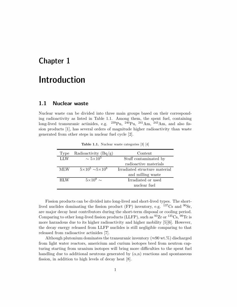
Nuclear waste can be divided into three main groups based on their correspond-ing radioactivity as listed in Table 1.1. Among them, the spent fuel, containinglong-lived transuranic actinides, e.g. 239Pu, 240Pu, 241Am, 243Am, and also fis-sion products [1], has several orders of magnitude higher radioactivity than wastegenerated from other steps in nuclear fuel cycle [2].
Table 1.1. Nuclear waste categories [3] [4]
Type Radioactivity (Bq/g) Content
LLW ∼ 5×10⁵ Stuff contaminated byradioactive materials
MLW 5×10⁵ ∼5×10⁸ Irradiated structure materialand milling waste
HLW 5×10⁸ ∼ Irradiated or usednuclear fuel
Fission products can be divided into long-lived and short-lived types. The short-lived nuclides dominating the fission product (FP) inventory, e.g. 137Cs and 90Sr,are major decay heat contributors during the short-term disposal or cooling period.Comparing to other long-lived fission products (LLFP), such as 93Zr or 135Cs, 99Tc ismore harzadous due to its higher radioactivity and higher mobility [5][6]. However,the decay energy released from LLFP nuclides is still negligible comparing to thatreleased from radioactive actinides [7].
Although plutonium dominates the transuranic inventory (≈90 wt.%) dischargedfrom light water reactors, americium and curium isotopes bred from neutron cap-turing starting from uranium isotopes will bring more difficulties to the spent fuelhandling due to additional neutrons generated by (α,n) reactions and spontaneousfission, in addition to high levels of decay heat [8].
1
2 CHAPTER 1. INTRODUCTION
Currently, a deep geologically repository is still a well-accepted solution of HLW.In order to reduce the burden on a geological disposal, the magnitude and the long-term radiotoxicity of HLW inventory needs to be minimized.
1.2 Transmutation
The terminology "transmutation" stands for a conversion process from one nuclideto another nuclide. When talking about the nuclear waste transmutation, it meansfissioning long-lived transuranic nuclides or converting LLFP nuclides into short-lived ones.
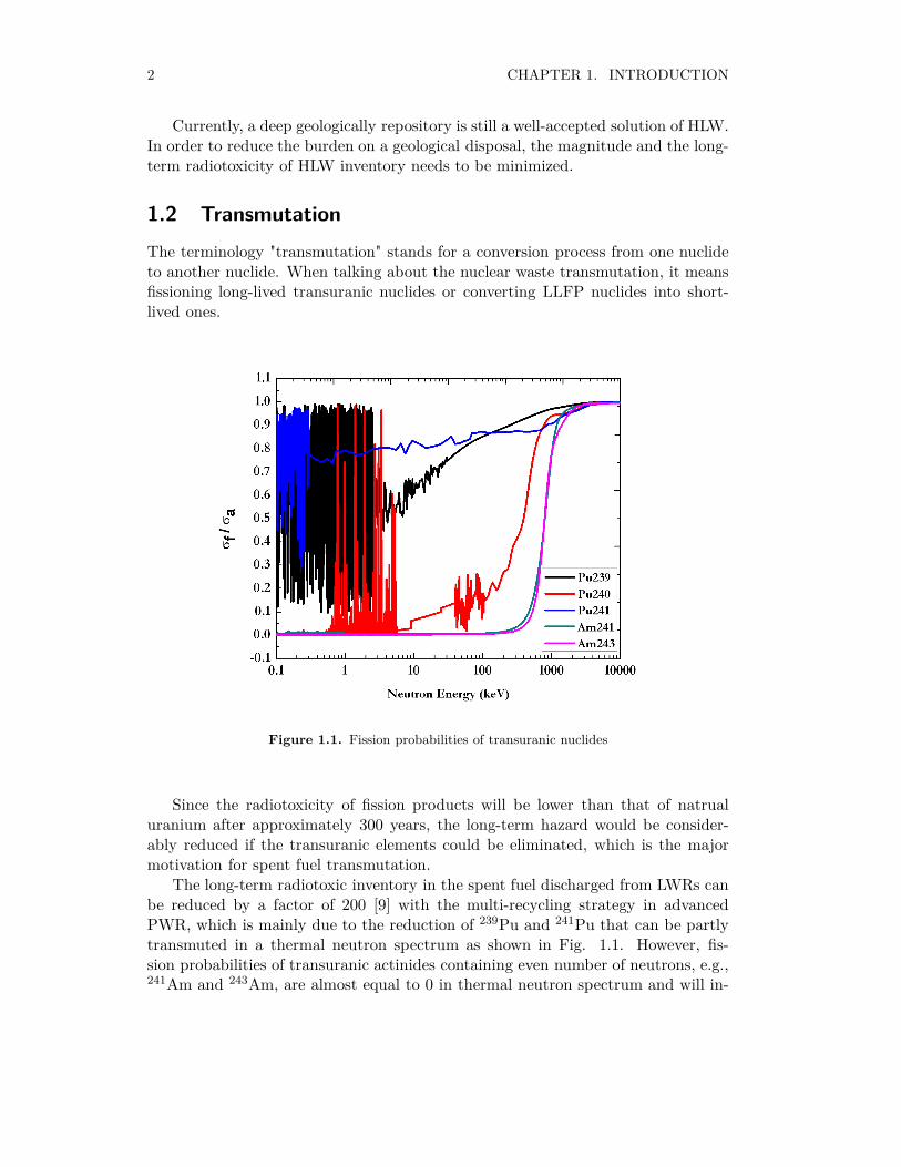
Figure 1.1. Fission probabilities of transuranic nuclides
Since the radiotoxicity of fission products will be lower than that of natrualuranium after approximately 300 years, the long-term hazard would be consider-ably reduced if the transuranic elements could be eliminated, which is the majormotivation for spent fuel transmutation.
The long-term radiotoxic inventory in the spent fuel discharged from LWRs canbe reduced by a factor of 200 [9] with the multi-recycling strategy in advancedPWR, which is mainly due to the reduction of 239Pu and 241Pu that can be partlytransmuted in a thermal neutron spectrum as shown in Fig. 1.1. However, fis-sion probabilities of transuranic actinides containing even number of neutrons, e.g.,241Am and 243Am, are almost equal to 0 in thermal neutron spectrum and will in-

1.2. TRANSMUTATION 3
crease with incident neutron energy. Thus, fast neutron facilities are more efficientto transmute transuranic nuclides especially minor actinides comparing to thermalneutron reactors, in which actinides with even neutron number will more likely bebred into heavier nuclides (e.g. 252Cf) instead of being fissioned. Besides, accu-mulation of 252Cf, being a strong neutron source, will arise after several rounds ofrecycling processes, which leads to more troubles for spent fuel handling.

Chapter 2
Candidate fast-neutron facilities
2.1 Fast neutron reactor
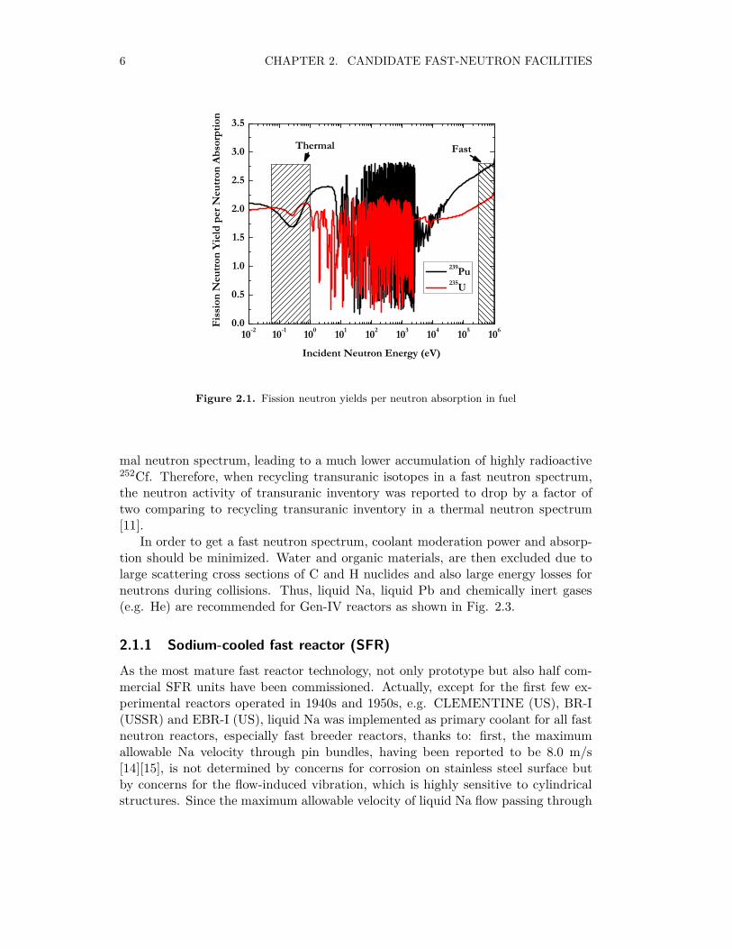
Fast neutron reactors, or fast reactors in short, are reactors using fast neutrons tosustain chain reactions. As can be observed in Fig. 2.1, more fission neutrons couldbe released per neutron absorption in fuel in a fast neutron spectrum comparingto cases in a thermal neutron spectrum [10] , besides the ones used to maintainthe chain reaction, there may be more neutrons available to breed fertile 238U intofissile 239Pu, through neutron capture followed by β decay reactions as shown in Eq.2.1. Although the fission neutron yield per fissile nuclide absorption higher than2.0, including one fission neutron needed to sustain chain reactions and the otherfission neutron used to breed new fissile nuclide, is adequate to provide a conversionratio equal to unity ideally, there are still possibilities for neutrons to leak out coreactive zone or to be captured by fission products, coolant, inner structure material,control rods in reactor core, which explains why U-Pu cycle in a well thermalizedspectrum is hardly feasible for achieving a conversion ratio ≥1.0.
n +238 U⇒239 U + γ ⇒239 Np + β− ⇒239 Pu + β− (2.1)
Fast neutron reactors were initially promoted to make a better usage of U re-sources by breeding fissile 239Pu nuclides from fertile 238U nuclides. Some countrieseven raised extensive research on fast breeder reactors aiming at producing morefissile materials, concerning the fissile material shortage. However, by 1970s, geo-logical exploration showed that the uranium shortage will not become a problem inthe near future, limiting the necessity for comissioning more fast reactors in the fol-lowing years. Recently, thanks to the higher transmutation capability of long-livedtransuranic isotopes comparing to light water reactors, fast reactors were promotedagain, aiming at reducing the HLW stockpile and shorten the time needed for geo-logical storage.
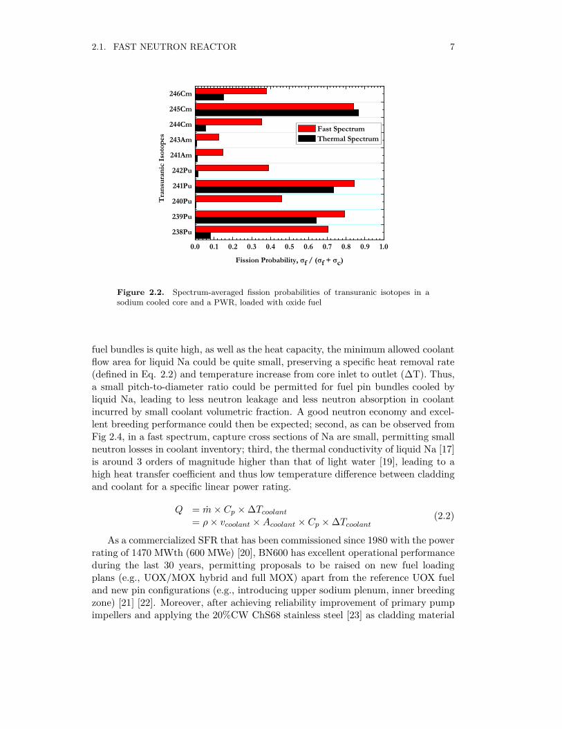
Besides, as can be noticed from Fig. 2.2, transuranic nuclides with even neutronnumbers, e.g., 238Pu, 240Pu, 242Pu, 241Am, 243Am, 244Cm and 246Cm, have muchhigher probabilities to undergo fission in a fast neutron spectrum than in a ther-
5
6 CHAPTER 2. CANDIDATE FAST-NEUTRON FACILITIES
10-2 10-1 100 101 102 103 104 105 1060.0
0.5
1.0
1.5
2.0
2.5
3.0
3.5
Fiss
ion
Neu
tron
Yiel
d pe
r Neu
tron
Abso
rptio
n
Incident Neutron Energy (eV)
239Pu 235U
Thermal Fast
Figure 2.1. Fission neutron yields per neutron absorption in fuel
mal neutron spectrum, leading to a much lower accumulation of highly radioactive252Cf. Therefore, when recycling transuranic isotopes in a fast neutron spectrum,the neutron activity of transuranic inventory was reported to drop by a factor oftwo comparing to recycling transuranic inventory in a thermal neutron spectrum[11].
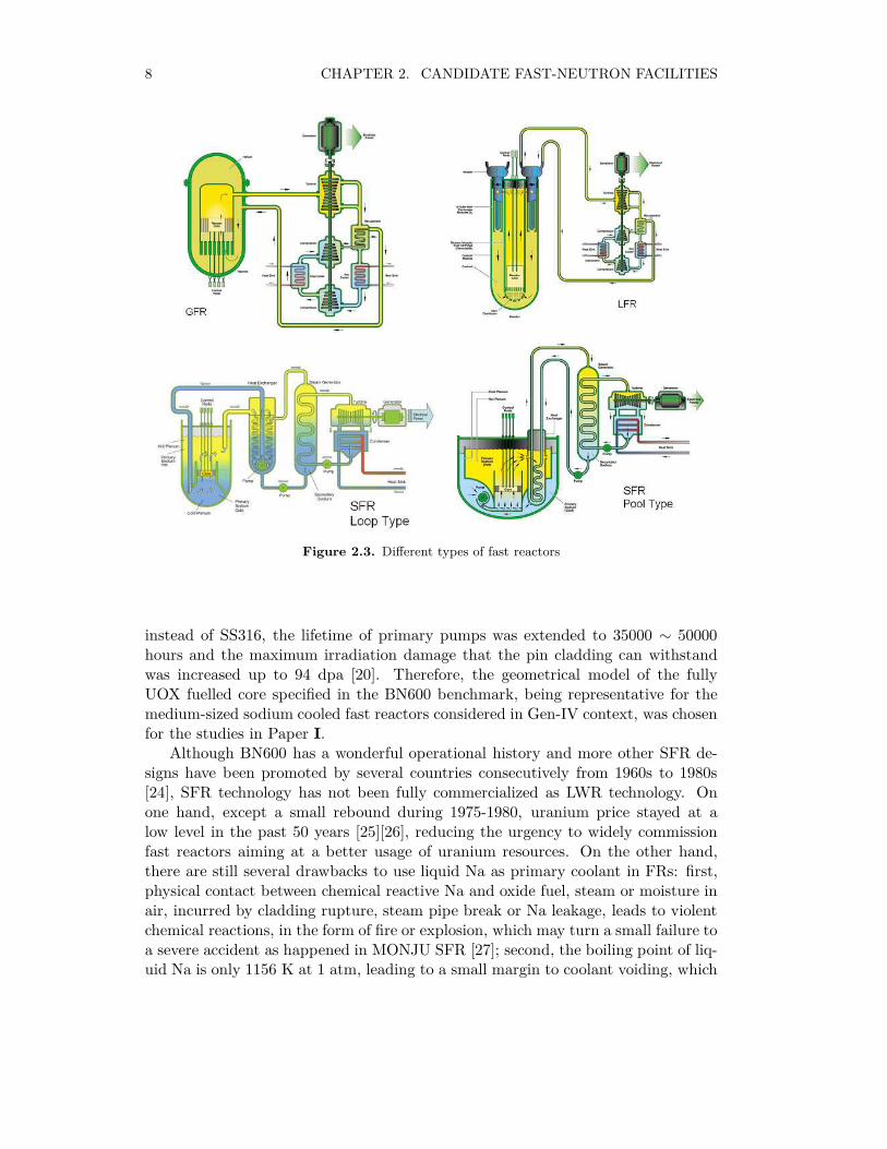
In order to get a fast neutron spectrum, coolant moderation power and absorp-tion should be minimized. Water and organic materials, are then excluded due tolarge scattering cross sections of C and H nuclides and also large energy losses forneutrons during collisions. Thus, liquid Na, liquid Pb and chemically inert gases(e.g. He) are recommended for Gen-IV reactors as shown in Fig. 2.3.
2.1.1 Sodium-cooled fast reactor (SFR)
As the most mature fast reactor technology, not only prototype but also half com-mercial SFR units have been commissioned. Actually, except for the first few ex-perimental reactors operated in 1940s and 1950s, e.g. CLEMENTINE (US), BR-I(USSR) and EBR-I (US), liquid Na was implemented as primary coolant for all fastneutron reactors, especially fast breeder reactors, thanks to: first, the maximumallowable Na velocity through pin bundles, having been reported to be 8.0 m/s[14][15], is not determined by concerns for corrosion on stainless steel surface butby concerns for the flow-induced vibration, which is highly sensitive to cylindricalstructures. Since the maximum allowable velocity of liquid Na flow passing through
2.1. FAST NEUTRON REACTOR 7
238Pu
239Pu
240Pu
241Pu
242Pu
241Am
243Am
244Cm
245Cm
246Cm
0.0 0.1 0.2 0.3 0.4 0.5 0.6 0.7 0.8 0.9 1.0
Fission Probability, f / ( f + c)
Tran
sura
nic
Isot
opes
Fast Spectrum Thermal Spectrum
Figure 2.2. Spectrum-averaged fission probabilities of transuranic isotopes in asodium cooled core and a PWR, loaded with oxide fuel
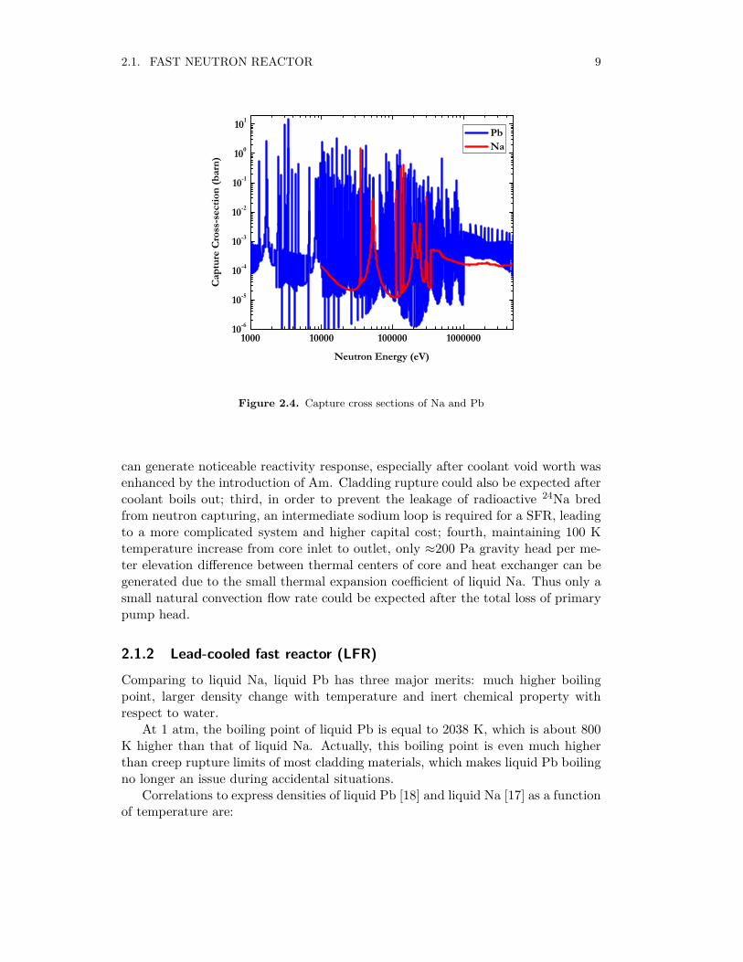
fuel bundles is quite high, as well as the heat capacity, the minimum allowed coolantflow area for liquid Na could be quite small, preserving a specific heat removal rate(defined in Eq. 2.2) and temperature increase from core inlet to outlet (∆T). Thus,a small pitch-to-diameter ratio could be permitted for fuel pin bundles cooled byliquid Na, leading to less neutron leakage and less neutron absorption in coolantincurred by small coolant volumetric fraction. A good neutron economy and excel-lent breeding performance could then be expected; second, as can be observed fromFig 2.4, in a fast spectrum, capture cross sections of Na are small, permitting smallneutron losses in coolant inventory; third, the thermal conductivity of liquid Na [17]is around 3 orders of magnitude higher than that of light water [19], leading to ahigh heat transfer coefficient and thus low temperature difference between claddingand coolant for a specific linear power rating.
Q = m× Cp ×∆Tcoolant= ρ× vcoolant ×Acoolant × Cp ×∆Tcoolant
(2.2)
As a commercialized SFR that has been commissioned since 1980 with the powerrating of 1470 MWth (600 MWe) [20], BN600 has excellent operational performanceduring the last 30 years, permitting proposals to be raised on new fuel loadingplans (e.g., UOX/MOX hybrid and full MOX) apart from the reference UOX fueland new pin configurations (e.g., introducing upper sodium plenum, inner breedingzone) [21] [22]. Moreover, after achieving reliability improvement of primary pumpimpellers and applying the 20%CW ChS68 stainless steel [23] as cladding material
8 CHAPTER 2. CANDIDATE FAST-NEUTRON FACILITIES
Figure 2.3. Different types of fast reactors
instead of SS316, the lifetime of primary pumps was extended to 35000 ∼ 50000hours and the maximum irradiation damage that the pin cladding can withstandwas increased up to 94 dpa [20]. Therefore, the geometrical model of the fullyUOX fuelled core specified in the BN600 benchmark, being representative for themedium-sized sodium cooled fast reactors considered in Gen-IV context, was chosenfor the studies in Paper I.
Although BN600 has a wonderful operational history and more other SFR de-signs have been promoted by several countries consecutively from 1960s to 1980s[24], SFR technology has not been fully commercialized as LWR technology. Onone hand, except a small rebound during 1975-1980, uranium price stayed at alow level in the past 50 years [25][26], reducing the urgency to widely commissionfast reactors aiming at a better usage of uranium resources. On the other hand,there are still several drawbacks to use liquid Na as primary coolant in FRs: first,physical contact between chemical reactive Na and oxide fuel, steam or moisture inair, incurred by cladding rupture, steam pipe break or Na leakage, leads to violentchemical reactions, in the form of fire or explosion, which may turn a small failure toa severe accident as happened in MONJU SFR [27]; second, the boiling point of liq-uid Na is only 1156 K at 1 atm, leading to a small margin to coolant voiding, which
2.1. FAST NEUTRON REACTOR 9
1000 10000 100000 100000010-6
10-5
10-4
10-3
10-2
10-1
100
101
Capt
ure
Cros
s-se
ctio
n (b
arn)
Neutron Energy (eV)
Pb Na
Figure 2.4. Capture cross sections of Na and Pb
can generate noticeable reactivity response, especially after coolant void worth wasenhanced by the introduction of Am. Cladding rupture could also be expected aftercoolant boils out; third, in order to prevent the leakage of radioactive 24Na bredfrom neutron capturing, an intermediate sodium loop is required for a SFR, leadingto a more complicated system and higher capital cost; fourth, maintaining 100 Ktemperature increase from core inlet to outlet, only ≈200 Pa gravity head per me-ter elevation difference between thermal centers of core and heat exchanger can begenerated due to the small thermal expansion coefficient of liquid Na. Thus only asmall natural convection flow rate could be expected after the total loss of primarypump head.
2.1.2 Lead-cooled fast reactor (LFR)
Comparing to liquid Na, liquid Pb has three major merits: much higher boilingpoint, larger density change with temperature and inert chemical property withrespect to water.
At 1 atm, the boiling point of liquid Pb is equal to 2038 K, which is about 800K higher than that of liquid Na. Actually, this boiling point is even much higherthan creep rupture limits of most cladding materials, which makes liquid Pb boilingno longer an issue during accidental situations.
Correlations to express densities of liquid Pb [18] and liquid Na [17] as a functionof temperature are:
10 CHAPTER 2. CANDIDATE FAST-NEUTRON FACILITIES
ρNa = 1012 − 0.2205T − 1.923 × 10⁻⁵T 2 + 5.637 × 10⁻⁹T 3
ρPb = 10587 − 1.2220(T − 600.6)(2.3)
From Eq. 2.3, it can be noticed that the density of liquid Pb has a higherdecrease than liquid Na for a unit temperature increase, leading to a higher naturalconvection driven by a unit elevation change between thermal centers in core andheat exchanger. Based on simulations performed by Maschek [59] and Zhang [66],approximately 40% residual flow could be expected for a liquid Pb cooled core, butonly less than 5% residue flow could be generated in BN600 type SFR after a totalloss of primary pump head.
Unlike chemically reactive Na, liquid Pb is chemically inert to H2O and steam.Thus, the steam generator could be installed inside the primary loop for LFRs,leading to a compact system and less capital cost for power plant construction.
Thanks to the lower boiling point comparing to liquid Pb, permitting reactors towork at a lower temperature level and thus leaving a bigger margin to clad failure,LBE alloy was first promoted. In Russia, the frst full-scaled prototype LBE cooledreactor (27/VT facility) was commissioned by 1959 based on research and designworks started from the early 1950s. The 27/VT facility was in operation for only tworuns due to accidents incurred by accumulation of impurity slags in the core inlet[33]. Later, two types of LBE-cooled primary circuit systems (OK-550 and BM-40/A) have been recommended for submarines by 1970s [29]. More recently, pureliquid Pb cooled BREST reactor and compact STAR-LM reactors were proposed byRussia and US, concerning accumulation of highly radioactive 210Po from neutroncapture of 209Bi. In the 6th Framework program, design work was performed on a400 MWth grade ADS design (known as EFIT-400) and a 600 MWe (1500 MWth)grade ADS design (known as ELSY), which are also cooled by liquid Pb [30] [31].
However, until now, no civilian LFRs have been commissioned. A major prob-lem when operating continuously at full power is corrosions on cladding and innerstructure materials incurred by inter-grannular penetration and mass transfer [32],especially for austenitic stainless steels with high concentrations of Ni, which hasthe highest solubility into liquid Pb comparing to other elements in stainless steelmatrix. The mass transfer from stainless steel to liquid Pb may lead to changes ofthe microstructure, composition, and surface morphology of the structural materi-als, affecting physical and mechanical properties of the structural materials, e.g.,embrittlement and drop of rupture strength. However, it has also been reportedthat this corrosion attack can be minimized if a thin protective oxide layer (2-3µm) could be formed on the steel surface [30]. In liquid Pb, the minimum oxygenconcentration required for the formation of protective oxide layer on surfaces ofFe-based alloys, equivalent to the oxygen potential ensuring the conditions to formthe least stable oxide (Fe3O4), can be calculated from Eq. 2.4, which is valid in thetemperature region from 603 to 1183 K [33][34].
logCFe,wt.% = 0.34 − 3450T
logCO,min,wt.% = −0.75logCFe,wt.% + 2.355 − 10600T
(2.4)
2.1. FAST NEUTRON REACTOR 11
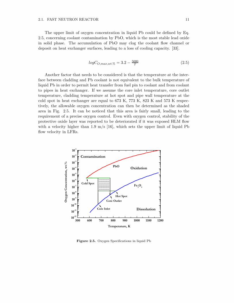
The upper limit of oxygen concentration in liquid Pb could be defined by Eq.2.5, concerning coolant contamination by PbO, which is the most stable lead oxidein solid phase. The accumulation of PbO may clog the coolant flow channel ordeposit on heat exchanger surfaces, leading to a loss of cooling capacity. [33].
logCO,max,wt.% = 3.2 − 5000T (2.5)
Another factor that needs to be considered is that the temperature at the inter-face between cladding and Pb coolant is not equivalent to the bulk temperature ofliquid Pb in order to permit heat transfer from fuel pin to coolant and from coolantto pipes in heat exchanger. If we assume the core inlet temperature, core outlettemperature, cladding temperature at hot spot and pipe wall temperature at thecold spot in heat exchanger are equal to 673 K, 773 K, 823 K and 573 K respec-tively, the allowable oxygen concentration can then be determined as the shadedarea in Fig. 2.5. It can be noticed that this area is fairly small, leading to therequirement of a precise oxygen control. Even with oxygen control, stability of theprotective oxide layer was reported to be deteriorated if it was exposed HLM flowwith a velocity higher than 1.9 m/s [16], which sets the upper limit of liquid Pbflow velocity in LFRs.
500 600 700 800 900 1000 1100 120010-12
10-11
10-10
10-9
10-8
10-7
10-6
10-5
10-4
10-3
10-2
10-1
++++++++++++++++++++++++++++++++++++++++++++++++++++++++++++
Core Inlet
Core OutletHot Spot
Oxidation
Contamination
PbO
Oxy
gen
Conc
entra
tion,
wt.%
Temperature, K
Fe3O4
Dissolution
Cold Spot++++++++++
Figure 2.5. Oxygen Specifications in liquid Pb

12 CHAPTER 2. CANDIDATE FAST-NEUTRON FACILITIES
2.1.3 Gas-cooled fast reactor (GFR)
The typical coolant used in a GFR is He. Unlike liquid Na or liquid Pb, He, being anon-active gas, is chemically and physically compatible with air, moisture and Fe-based alloys, permitting the usage of a direct Brayton gas turbine cycle, by which ahigher thermal efficiency could be expected [35]. Besides, since He is already in gasphase at normal operating temperature, coolant boiling or reactivity response fromcoolant voiding may not be issues any more, providing a better safety performanceand also permitting more than 3 times bigger temperature increase from core inletto outlet comparing to SFRs and LFRs.
Current GFR researches are mainly based on design processes and operationalexperiences of several graphite-moderated thermal spectrum gas-cooled reactors,e.g., AVR (Germany), HTTR (Japan), HTR-10 (China), and design studies of fastspectrum gas-cooled reactors, e.g., GCFR (US & EU) and the Allegro reactor. Theseresearches are mainly on selecting a proper fuel form, material for cladding and coreconfiguration to provide efficient conversion of fertile U and a better managementof transuranic inventories, preserving system integrity and compatibility [36]. Theconceptual design of a prototype Allegro reactor with a capacity of 50-80 MWth isplanned to be accomplished by 2019 and commissioned by 2025 according to R&Dplans [37].
Before achieving these targets, there are still some technical challenges need tobe faced. First, the radiation resiliency of candidate fuel forms, e.g., actinide-carbideand ceramic-ceramic, for GFR operating conditions (1673 K, 20%h.a. burnup and150 dpa irradiation dose) should be further investigated [36]. Second, althoughadvanced ceramic materials have been promoted for in-vessel structure usage, theircapabilities to withstand temperatures up to 1873 K and fast neutron damage stillneed to be validated. Third, as can be noticed from Eq. 2.2, the heat removalrate is linearly related to coolant temperature increase (∆T), cross-sectional areaof coolant flow channel (A), coolant velocity (v), coolant heat capacity (Cp) andcoolant density (ρ). Since ∆T is limited by material reliability, A is restricted bythe concern of neutron leakage and neutron economy, v is limited by the concernof erosion on in-vessel structure with the existence of impurities and Cp of He wasreported to be constant in a wide temperature range [38], He density should beincreased by enhancing coolant pressure in GFR system (normally ≥4 MPa [39])in order to achieve a higher cooling capability. Since He density will intensivelydecrease according to Eq. 2.6 during depressurization [38], a passive system toprovide back-up pressure is then required in order to maintain sufficient coolingcapability for decay heat removing.
ρHe(kg/m3) = 48.14 ×
P (atm)
T (K)× [1 + 0.4446 ×
P (atm)
T (K)1.2]−1 (2.6)

2.2. ACCELERATOR DRIVEN SYSTEM 13
2.2 Accelerator driven system
Since the consumption rate of MA will increase with the fraction of MA in fuelfor fast reactors, the maximum allowable content of MA should be determinedin order to maximize the transmutation capability of fast reactors. However, ithas been reported that loading FRs with only MA inventory, may lead to safety-related problems due to degradations of safety parameters incurred by the absenceof fertile U. Besides, higher content of MA, especially Am, may lead to furtherdegradations of safety parameters, such as a reduction of effective delayed neutronfraction, a reduction of the Doppler constant and an increase in coolant void worth[40]. Therefore, the maximum allowable fraction of Am homogeneously loaded intoSFRs has been investigated and first quoted as 2.5% [41]. Recently, this limit hasbeen uplifted to 5% for SFRs loaded with metallic fuels [42]. If target sub-assemblieswere introduced, this limit for target sub-assemblies may be higher [43]. LFRs aremore robust systems than SFRs, regarding core safety during transients, thanks toits high boiling point and excellent natural convection behavior. Thus, up to 10%MA, equivalent to 7% Am, was claimed to be acceptable for a medium LFR with600 MWe power rating without considering core performances during transients[44]. For a 2400 MWth grade GFR, only 1.1% of MA was proposed to be loaded,corresponding to self-recycling [45]. Hence, in order to host higher fraction of minoractinides aiming at higher MA transmutation rates, FRs should be designed tooperate in a sub-critical mode, which can provide improved flexibility and safetycharacteristics, concerning degradation of core safety performance incurred by minoractinides introduction. The sub-critical core needs to be driven by an externalneutron source. In order to generate sufficient neutrons from spallation reactions,the proton beam should be accelerated before bombarding an heavy metal target,giving rise to the term the terminology "Accelerator Driven System (ADS)".
Before further investigations, a terminology named "the energy gain (G)", equallingthe ratio of the total power of system (Ptot) to the proton beam power (Pacc), shouldbe introduced in order to parameterize the influence from changes of target and coredesigns on power amplification of system. The energy gain of ADS can be calcu-lated by Eq. 2.7, in which keff is the multiplication factor of system, Ef is theaveraged energy released per fission reaction, ν is the fission yield, Ep is the protonbeam energy and ψ∗ is the proton source efficiency [50]. Thus, in order to maximizethe energy gain aiming at a better system economy, keff , ν, Ef and ψ∗ should bemaximized and Ep should be minimized. Since keff is limited by safety concerns,Ep affects the spallation neutron yield, ν and Ef are assumed to be constant fora specific fuel composition, the energy gain could be increased by optimising thesystem design aiming at a higher ψ∗.
G =PtotPacc
=keff
1− keff
EfνEp
ψ∗ (2.7)
14 CHAPTER 2. CANDIDATE FAST-NEUTRON FACILITIES
0.0 0.2 0.4 0.6 0.8 1.0 1.2 1.4 1.6 1.8 2.00
5
10
15
20
25
30
Neu
tron
Yiel
d
Proton Energy (GeV)
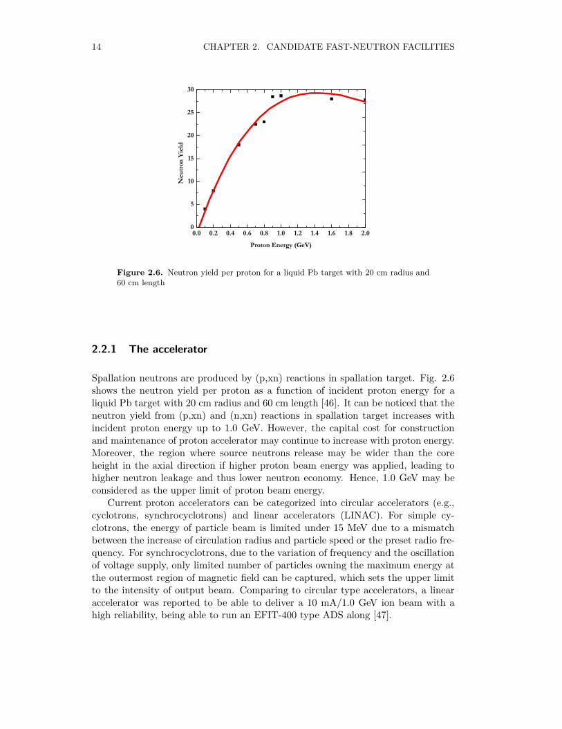
Figure 2.6. Neutron yield per proton for a liquid Pb target with 20 cm radius and60 cm length
2.2.1 The accelerator
Spallation neutrons are produced by (p,xn) reactions in spallation target. Fig. 2.6shows the neutron yield per proton as a function of incident proton energy for aliquid Pb target with 20 cm radius and 60 cm length [46]. It can be noticed that theneutron yield from (p,xn) and (n,xn) reactions in spallation target increases withincident proton energy up to 1.0 GeV. However, the capital cost for constructionand maintenance of proton accelerator may continue to increase with proton energy.Moreover, the region where source neutrons release may be wider than the coreheight in the axial direction if higher proton beam energy was applied, leading tohigher neutron leakage and thus lower neutron economy. Hence, 1.0 GeV may beconsidered as the upper limit of proton beam energy.
Current proton accelerators can be categorized into circular accelerators (e.g.,cyclotrons, synchrocyclotrons) and linear accelerators (LINAC). For simple cy-clotrons, the energy of particle beam is limited under 15 MeV due to a mismatchbetween the increase of circulation radius and particle speed or the preset radio fre-quency. For synchrocyclotrons, due to the variation of frequency and the oscillationof voltage supply, only limited number of particles owning the maximum energy atthe outermost region of magnetic field can be captured, which sets the upper limitto the intensity of output beam. Comparing to circular type accelerators, a linearaccelerator was reported to be able to deliver a 10 mA/1.0 GeV ion beam with ahigh reliability, being able to run an EFIT-400 type ADS along [47].

2.2. ACCELERATOR DRIVEN SYSTEM 15
Figure 2.7. Window and windowless targets
2.2.2 The spallation target
Target material
Until now, LBE, Hg and liquid Pb have been proposed for high power spallationtargets thanks to their excellent performance for source neutron production (highneutron yield per incident proton) and high heat removal capacity (ρCP ). Con-cerning evaporation of target materials and volatilization of spallation productswhen connecting to a vacuum cavity required by accelerators, a window was oncerecommended for spallation target to separate the vacuum cavity and the spalla-tion zone. However, harsh working conditions, including high working temperature,HLM corrosion and irradiation defects, may lead to a target window failure dueto accumulations of thermal, irradiation and mechanical loads [48]. A windowlesstarget without a physical separation between the vacuum cavity and the liquid tar-get material was then proposed as shown in Fig. 2.7. However, adequate pumpingcapacity is required to maintain the high vacuum condition above target surfaceand prevent impurities invasion from target zone into proton beam line. LBE andPb are then more suitable for a windowless target usage rather than Hg, thanksto their four orders of magnitude lower vapour pressure at the normal operatingtemperature [49].

16 CHAPTER 2. CANDIDATE FAST-NEUTRON FACILITIES
In Paper II, the nitride fuelled ADS employs a windowless spallation target,which is cooled by liquid Pb instead of LBE in order to prevent the accumulationof highly radioactive 210Po from 209Bi through (n,γ) reactions followed by β decayreactions.
Target size
Since the fast fission threshold of Am and other fertile nuclides is in the region0.5-1.0 MeV as shown in Fig. 1.1, higher moderation on liquid Pb in target blockpermits less spallation neutrons to enter into the most effective energy region forfissioning fertile nuclides, leading to smaller proton source efficiency [50]. Thus,the spallation target size should be minimized, preserving sufficient heat removalcapability. In the suggested ADS design, thanks to the employment of nitride fuel,smaller pin pitch and compact spallation target, the proton source efficiency couldbe enhanced by 80% comparing to the reference EFIT-400 design. Thus, the protoncurrent and proton beam power required for the system could be reduced by 67%[51], leading to less deposit heat into spallation target, which permits the reductionof spallation target size.
2.2.3 The subcritical core
Similar to critical reactors, the sub-critical core in ADS also consists of sub-assemblies,which is in hexagonal geometry in order to achieve better radial power profile andenable a better fit of the spallation target. However, since the safety of sub-criticalcore can be enhanced due to the bigger margin to prompt criticality than criticalfacilities, higher minor actinides concentration, leading to further deterioration ofinherent safety, can be permitted. In the reference EFIT-400 design, U-free oxidefuel containing 54.3 at.% minor actinides was proved to be allowable, providing aMA consumption rate of ≈42 kg/TWhth [52].
Since the melting point of LBE (44.5%Pb-55.5%Bi) (397 K, at 1 atm) is around200 K lower than that of Pb, it is used as the primary coolant instead of liquidPb for the nitride fuelled ADS investigated in Paper II aiming at a lower coolanttemperature at core inlet, which limits thermal loading and corrosion effect oncladding and in-vessel structures. However, severe inter-grannular penetration andmass transfer have also been reported for stainless steel in LBE, leading to therequirement of oxide protective layer as the case for liquid Pb. The minimum oxygenconcentration required for the formation of protective oxide layer on surfaces of Fe-based alloys can be calculated from Eq. 2.8, which is valid in the region from 823to 1053 K. Concerning coolant contamination incurred by PbO accumulation, theupper limit of oxygen concentration in liquid Pb could be defined by using Eq.2.9, which is valid in 673 - 973 K. Therefore, oxygen control is also required for aLBE-cooled system.
logCFe,wt.% = 2.01 − 4380T
logCO,min,wt.% = −0.75logCFe,wt.% + 1.2375 − 9757T
(2.8)
2.2. ACCELERATOR DRIVEN SYSTEM 17
logCO,max,wt.% = 1.2 − 3400T (2.9)
In the nitride fuelled ADS, the pin pitch is reduced from 1.35 cm (for the refer-ence EFIT-400 design) to 1.20 cm in order to reduce the coolant volumetric fractionin system, aiming at a better neutron economy in the sub-critical core. However,since the velocity of LBE flow washing stainless steel bundles is restricted under1.9 m/s as discussed above, the reduction of pin pitch may lead to reduction ofcoolant flowrate per pin not only during the normal operating condition but alsoduring transients. In order to maintain an adequate margin to cladding rupture,the austenitic 15/15Ti stainless steel with enhanced thermal and irradiation creepresistance, instead of the ferritic-martensitic T91 stainless steel inplemented in thereference EFIT-400 design, is used for the suggested ADS design.


Chapter 3
Simulation tools
3.1 SERPENT Monte Carlo code
In this thesis, the reactor operating parameters and reactivity coefficients were eval-uated by the SERPENT Monte Carlo code based on the JEFF-3.1 data library. TheSERPENT Monte Carlo code was initiated as the program "Probalistic ScatteringGame" starting from 2004 in VTT Technical Research Centre in Finland [53]. Sim-ilar to the MCNP and MCB Monte Carlo codes, a universe based geometry modelis applied to describe the configuration of fuel pins and sub-assemblies. The burnupcalculation is realized by solving the Bateman equations with the TransmutationTrajectory Method (TTA) and expressed with time or burn rate steps. The JEFF-3.1.1 decay data library and the JEFF-3.1 fission yield data library have been usedfor the burnup calculation.
Comparing to existing most-used Monte Carlo codes, e.g. MCNP, the SER-PENT Monte Carlo code has two merits. First, Monte Carlo calculation is accel-erated by 5 to 15 times faster thanks to: 1. evenly subdividing the energy gridin cross section spectrums, which reduces the time consumption for iteration pro-cess when generating cross section data; 2. combining conventional ray-tracing anddelta-tracking methods enhances neutron transport calculation efficiency. Second,homogenized few-group constants, e.g. diffusion rates, effective delayed neutronfractions, and statistical error estimation can be obtained directly by includingsome newly developed scripts.
The SERPENT Monte Carlo code has been preliminarily validated with respectto MCNP and the deviation between these two codes is reported to be less than 2%[54].
3.2 SAS4A/SASSYS transient analysis code
The Safety Analysis System (SAS) was initially written by D. R. MacFarlane asa PhD thesis at the middle of 1960s and upgraded by the staff at safety analysissection at Argonne national laboratory in the following years, aiming at licencing
19
20 CHAPTER 3. SIMULATION TOOLS
governmental sponsored research facilities by accomplishing safety analysis.In this thesis, all transient analysis were performed by applying the SAS4A/SASSYS
code (version 3.1), which has been extensively validated based on experimental dataobtained from the TREAT M-series, EBR-II SHRT and GEMS tests. This versioncode is then qualified for licensing liquid metal (e.g., liquid Na, liquid Pb and Pb/Bieutectic alloy) cooled reactor cores loaded with oxide or metallic fuels, by means oftransient accident simulations, such as Loss-of-Flow (LOF), Transient-over-Power(TOP) and Beam Trip (BT).
In the SAS4A code, one or more sub-assemblies sharing similar thermophys-ical properties and thermal hydraulic structure are represented by one thermal-hydraulic channel. A whole-core model is formed by several channels. Heat transferbetween fuel, cladding and structure is modeled with a two-dimensional (r/z) heatconduction equation. Heat transfer between cladding and coolant is evaluated bysimulating single and two-phase coolant thermal-hydraulics with a one-dimensionalnon-equilibrium, homogenous coolant flow model in axial direction. Introduction ofmodels for ex-reactor coolant systems enables the SAS4A/SASSYS code to analyzeLOHS-involved transients.
The neutronic behavior of reactor core during transients is evaluated by applyingthe point kinetic model as shown in Eq. 3.1, in which p(t), ρ(t), β(t), Λ(t), λk,ck(t) and s(t) stand for the power, the reactivity, the delayed neutron fraction, theprompt neutron life time, the group-wise decay constants, the group-wise decayprecursor fractions and the source term of core as a function of time [55].
dp(t)
dt=ρ(t)− β(t)
Λ(t)× p(t) +
∑
k
λkck(t) + s(t) (3.1)
The point kinetic model is an appoximation to the time-dependent continuousenergy diffusion equation. It has been reported that deviations from the usage ofpoint kinetic approximation in sub-critical systems is fairly small (≤5.0%). However,it has also been indicated that the precision of the point kinetic model decreases re-markably when approaching criticality, especially in the case of local perturbations,such as single control rod withdrawal [56], due to slower migration of spatial per-turbations. However, if non-local perturbation is assumed to be introduced duringLOF and TOP transients, simulation results obtained from the point kinetic modelare still considered to be reliable [57].
The net reactivity change during transients dρ(t) could be calculated by sum-ming up reactivity feedbacks from six components as listed in Eq. 3.2, standingfor programmed/user-defined, the Doppler effect, fuel pin axial expansion, coolantdensity change, core radial expansion and control rod drive expansion respectively.For ADS, since reactivity swing and reactor shutdown could be managed by ad-justing spallation neutron source, control rods are not required. Thus, expansionof control rod drive, contributing reactivity feedback, is not considered in transientsimulation for the nitride fuelled ADS.

3.2. SAS4A/SASSYS TRANSIENT ANALYSIS CODE 21
dρ(t) = dρp(t) + dρD(t) + dρd(ax) + dρcoolant(t) + dρre(t) + dρcr(t) (3.2)

Chapter 4
SERPENT and SAS4A/SASSYS models
4.1 SERPENT models
4.1.1 For BN600
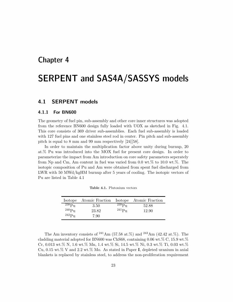
The geometry of fuel pin, sub-assembly and other core inner structures was adoptedfrom the reference BN600 design fully loaded with UOX as sketched in Fig. 4.1.This core consists of 369 driver sub-assemblies. Each fuel sub-assembly is loadedwith 127 fuel pins and one stainless steel rod in center. Pin pitch and sub-assemblypitch is equal to 8 mm and 99 mm respectively [24][58].
In order to maintain the multiplication factor above unity during burnup, 20at.% Pu was introduced into the MOX fuel for present core design. In order toparameterize the impact from Am introduction on core safety parameters seperatelyfrom Np and Cm, Am content in fuel was varied from 0.0 wt.% to 10.0 wt.%. Theisotopic composition of Pu and Am were obtained from spent fuel discharged fromLWR with 50 MWd/kgHM burnup after 5 years of cooling. The isotopic vectors ofPu are listed in Table 4.1
Table 4.1. Plutonium vectors
Isotope Atomic Fraction Isotope Atomic Fraction238Pu 3.50 239Pu 52.88240Pu 23.82 241Pu 12.90242Pu 7.90
The Am inventory consists of 241Am (57.58 at.%) and 243Am (42.42 at.%). Thecladding material adopted for BN600 was ChS68, containing 0.06 wt.% C, 15.9 wt.%Cr, 0.013 wt.% N, 1.6 wt.% Mn, 1.4 wt.% Si, 14.5 wt.% Ni, 0.3 wt.% Ti, 0.03 wt.%Cu, 0.15 wt.% V and 2.2 wt.% Mo. As stated in Paper I, depleted uranium in axialblankets is replaced by stainless steel, to address the non-proliferation requirement
23
24 CHAPTER 4. SERPENT AND SAS4A/SASSYS MODELS
Figure 4.1. Geometrical layouts of pin (left), sub-assembly (middle) and core (right)for BN600 [15]
for Gen-IV system. Steel shielding assemblies (SSA) are filled with the ChS68 stain-less steel. Boron reflector assemblies consist of pins loaded with B4C, containing80.0 at% 10B.
Based on geometrical and compositional details stated above, a 3-D SERPENTmodel was constructed as shown in Fig. 4.2.
4.1.2 For the nitride fuelled ADS design
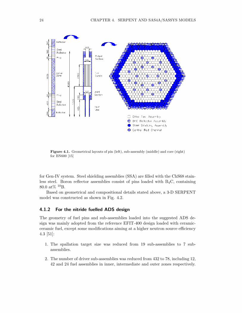
The geometry of fuel pins and sub-assemblies loaded into the suggested ADS de-sign was mainly adopted from the reference EFIT-400 design loaded with ceramic-ceramic fuel, except some modifications aiming at a higher neutron source efficiency4.3 [51]:
1. The spallation target size was reduced from 19 sub-assemblies to 7 sub-assemblies.
2. The number of driver sub-assemblies was reduced from 432 to 78, including 12,42 and 24 fuel assemblies in inner, intermediate and outer zones respectively.

4.1. SERPENT MODELS 25
Figure 4.2. SERPENT model for BN600, top view (above) and side view (below)
26 CHAPTER 4. SERPENT AND SAS4A/SASSYS MODELS
3. The pin pitch was reduced from 1.35 cm to 1.20 cm, permiting 217 pins(including 216 fuel pins + 1 stainless steel pin in center) instead of 169 pins(including 168 fuel pins + 1 stainless steel pin in center) to be settled in eachsub-assembly.
In order to minimize the radial power peaking factor, inert matrix nitride fuel,containing 78.1 vol.%, 73.9 vol.% and 66.1 vol.% ZrN, was loaded into the inner,intermediate and outer zones respectively. The atomic fraction of Pu in HM wasfixed to 43.5%. The MA inventory consists of Np (4.0 at.%), Am (91.8 at.%) andCm (4.2 at.%).
Figure 4.3. Geometrical layouts of pin (Left), sub-assembly (middle) and core(right) for the suggested ADS design [59]
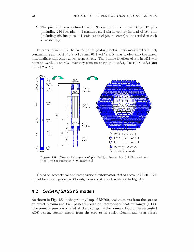
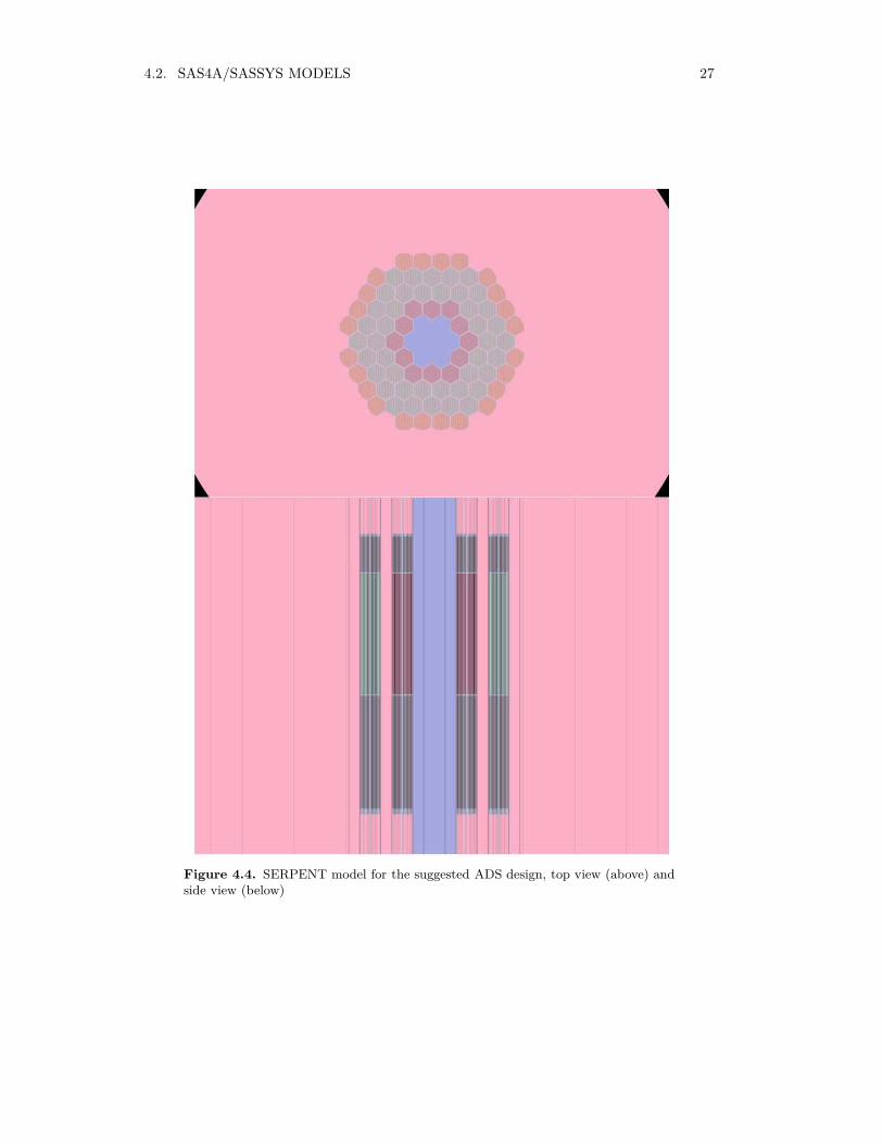
Based on geometrical and compositional information stated above, a SERPENTmodel for the suggested ADS design was constructed as shown in Fig. 4.4.
4.2 SAS4A/SASSYS models
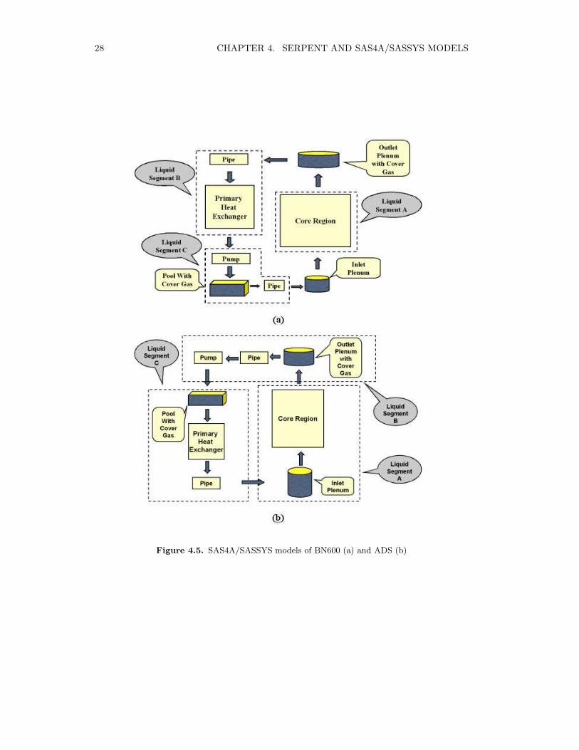
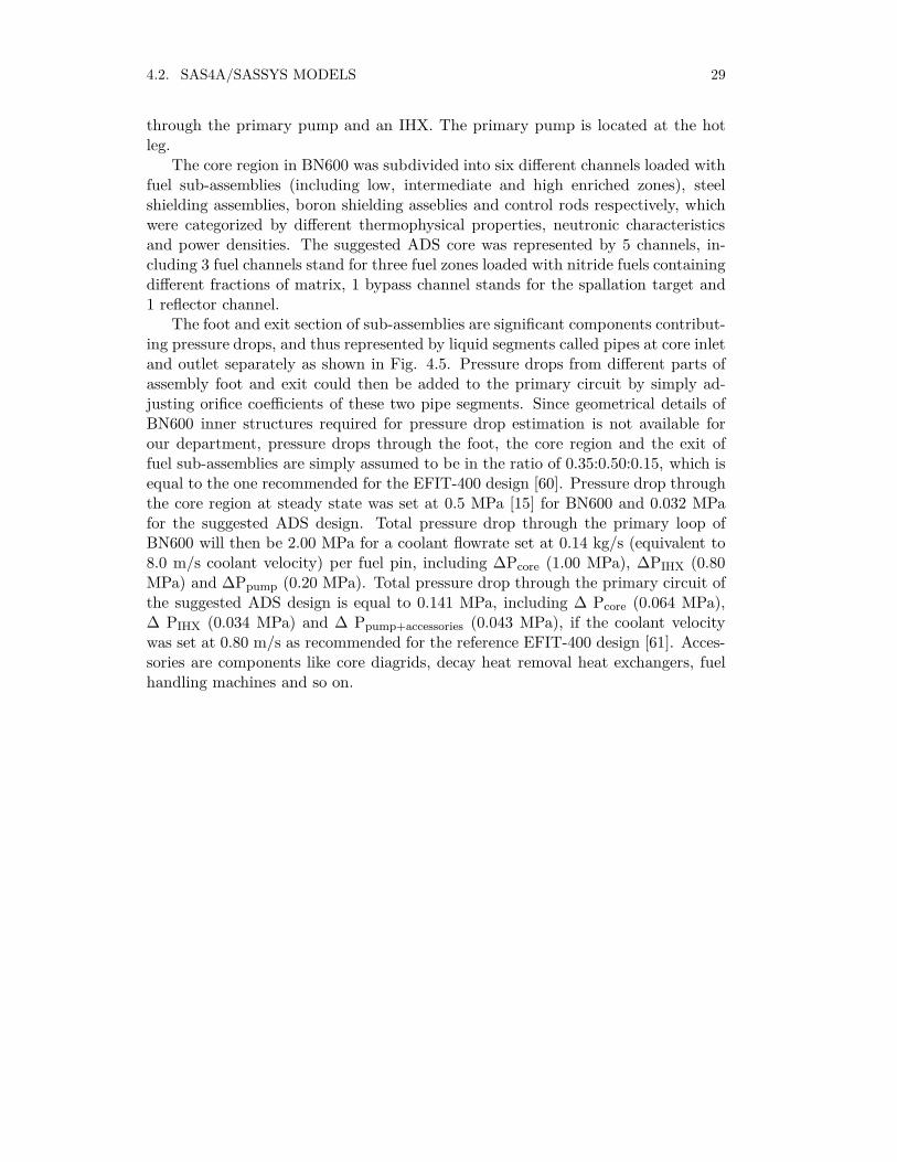
As shown in Fig. 4.5, in the primary loop of BN600, coolant moves from the core toan outlet plenum and then passes through an intermediate heat exchanger (IHX).The primary pump is located at the cold leg. In the primary loop of the suggestedADS design, coolant moves from the core to an outlet plenum and then passes
4.2. SAS4A/SASSYS MODELS 27
Figure 4.4. SERPENT model for the suggested ADS design, top view (above) andside view (below)
28 CHAPTER 4. SERPENT AND SAS4A/SASSYS MODELS
Figure 4.5. SAS4A/SASSYS models of BN600 (a) and ADS (b)
4.2. SAS4A/SASSYS MODELS 29
through the primary pump and an IHX. The primary pump is located at the hotleg.
The core region in BN600 was subdivided into six different channels loaded withfuel sub-assemblies (including low, intermediate and high enriched zones), steelshielding assemblies, boron shielding asseblies and control rods respectively, whichwere categorized by different thermophysical properties, neutronic characteristicsand power densities. The suggested ADS core was represented by 5 channels, in-cluding 3 fuel channels stand for three fuel zones loaded with nitride fuels containingdifferent fractions of matrix, 1 bypass channel stands for the spallation target and1 reflector channel.
The foot and exit section of sub-assemblies are significant components contribut-ing pressure drops, and thus represented by liquid segments called pipes at core inletand outlet separately as shown in Fig. 4.5. Pressure drops from different parts ofassembly foot and exit could then be added to the primary circuit by simply ad-justing orifice coefficients of these two pipe segments. Since geometrical details ofBN600 inner structures required for pressure drop estimation is not available forour department, pressure drops through the foot, the core region and the exit offuel sub-assemblies are simply assumed to be in the ratio of 0.35:0.50:0.15, which isequal to the one recommended for the EFIT-400 design [60]. Pressure drop throughthe core region at steady state was set at 0.5 MPa [15] for BN600 and 0.032 MPafor the suggested ADS design. Total pressure drop through the primary loop ofBN600 will then be 2.00 MPa for a coolant flowrate set at 0.14 kg/s (equivalent to8.0 m/s coolant velocity) per fuel pin, including ∆Pcore (1.00 MPa), ∆PIHX (0.80MPa) and ∆Ppump (0.20 MPa). Total pressure drop through the primary circuit ofthe suggested ADS design is equal to 0.141 MPa, including ∆ Pcore (0.064 MPa),∆ PIHX (0.034 MPa) and ∆ Ppump+accessories (0.043 MPa), if the coolant velocitywas set at 0.80 m/s as recommended for the reference EFIT-400 design [61]. Acces-sories are components like core diagrids, decay heat removal heat exchangers, fuelhandling machines and so on.


Chapter 5
Effects from the introduction ofamericium
Fresh Am is a white lustrous metal. The melting point and density of pure Amare 1267 K and 13.67 g/cm3 (293 K) respectively [62]. In dry atmosphere, Ammetal will be tarnished by heat generated from spontaneous fission reactions and αirradiation.
Figure 5.1. Relations of the most important actinides, via α-decay, β-decay andneutron capture reactions
31
32 CHAPTER 5. EFFECTS FROM THE INTRODUCTION OF AMERICIUM
The first identified Am isotope is 241Am, which was synthesized from successiveneutron capture reactions of Pu by Seaborg et al. at 1944 [63]. Apart from 241Am,at least 10 Am isotopes with atomic mass ranging from 237 to 247 have beensynthesized, in which 237Am has the longest half-life time equaling 7400 years.
Like other transuranic nuclides with atomic numbers higher than 95, all Amisotopes can undergo α decay and spontaneous fission reactions. α particles releasedfrom α decay reactions of 241Am has the average energy of 5.48 MeV, which isthree times higher than those released from α decay reactions of 226Ra. γ particlesdischarged during α decay and spontaneous fission reactions have the average energyof around 59 keV and 7 MeV [64] respectively. Thus, accumulation of Am nuclidesleads to difficulties for fuel handling.
Nevertheless, since fission probabilities of the major Am isotopes are close tozero in a thermal neutron spectrum as can be noticed from Fig. 1.1, Am nuclides aremore likely to be bred to 252Cf, which is a strong neutron source and heat emitter,instead of being fissioned if they are recycled in a thermal spectrum as shown in Fig.5.1. It has been reported that the equilibrium concentration in a fast spectrum of Cfand the corresponding neutron reactivity will be 2-3 orders of magnitude lower thanin a thermal spectrum. Thus, fast neutron facilities are better suited to implementtransmutation of Am [65].
For the suggested ADS design, isotopic composition of fuel and core design pa-rameters have been adjusted to achieve a higher proton source efficiency comparingto the reference EFIT-400 design, preserving the same minor actinide transmutationrate equalling 42 kg/TWh. Thus, in Paper II, the major task is to confirm the sug-gested ADS design by investigating core safety performances during the postulatedtransients.
For fast critical reactors, the consumption rate of Am is highly dependent on theratio between Am and Pu in the fresh fuel. A larger Am/Pu ratio permits a higherAm burning rate, in terms of kilogram Am consumed per TWh power produced.However, since Am has a detrimental effect on essential safety parameters of reactorcore, e.g. the effective delayed neutron fraction, the Doppler constant, the coolantvoid worth and the axial/radial expansion reactivity coefficient, a careful analysisof transient performance as a function of Am concentration in the fuel must beperformed, also taking the degradation of thermophysical properties into account.
5.1 Effects on safety parameters
Effects from the introduction of Am on reactivity coefficients and core performanceparameters were evaluated by modifying MOX fuel with different fractions of Amand then loaded into a SERPENT model derived from the geometrical design ofBN600 [66]. Calculation results are summarized into Fig. 5.2.

5.1. EFFECTS ON SAFETY PARAMETERS 33
34 CHAPTER 5. EFFECTS FROM THE INTRODUCTION OF AMERICIUM
5.1.1 The effective delayed neutron fraction
Neutrons released from fission reactions can be divided into prompt and delayedneutrons. A prompt neutron is a neutron emitted immediately from fission reac-tions. A delayed neutron is a neutron emitted from fission products decay anytimefrom several milliseconds (ms) to about 55 seconds (such as 87Br) [67]. The delayedneutron fraction (β) is then defined as the number of delayed neutrons divided bythe number of total fission neutrons. The effective delayed neutron fraction (βeff )is defined as the fraction of fission inducing neutrons that were born as delayedneutrons.
Since capture cross section of 241Am is 5 times higher than that of 238U forthe average energy of delayed neutrons (≈0.5 MeV), the effectiveness of delayedneutrons will decrease in proportion to Am content as can be noticed from Fig.5.2. Smaller βeff may lead to: first, shorter mean generation time (Λ) of fissionneutrons, limiting the time for non-malignant responses from either the manualoperation or inherent safety characteristics; second, higher sensitivity of core powerto reactivity fluctuations according to Eq. 3.1. The increase of βeff during burnupis mainly due to the consumption of Am nuclides.
5.1.2 The Doppler constant
The Doppler effect of fertile nuclides is mainly from the Doppler broadening ofcapture resonances of 238U and 240Pu, permitting more neutrons distributed in awider energy spectrum to be captured, which leads to a lower effective multiplicationfactor. The Doppler constant is then used to correlate the reactivity change withfuel temperature change as shown in Eq. 5.1, in which ρ(T1) and ρ(T2) stand forcore reactivities at fuel temperatures T1 and T2.
KD = −ρ(T2)− ρ(T1)
ln(T2/T1)(5.1)
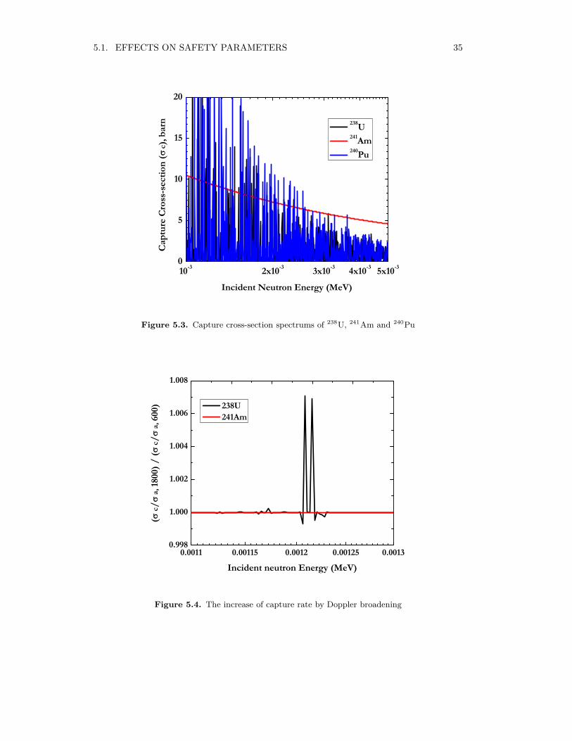
As can be observed from Fig. 5.2, the Doppler effect will be weakened by afactor of two when Am content was increased from 1.0 wt.% to 10.0 wt.% becausethe introduction of Am permits less fission neutrons to enter the energy region wherethe Doppler effect is most efficient and also weakens the Doppler broading effects of238U and 240Pu by covering their resonance capture regions with that of 241Am asshown in Fig. 5.3, whose Doppler broadening effect is weaker as shown in Fig. 5.4.
The increase of the Doppler constant shown in Fig. 5.2 is the consequence ofAm consumption during burnup and also accumulations of fission products, whichfunction as extra moderators in fuel matrix, permitting more fission neutrons toenter the most effective energy region for the Doppler effect as discussed in PaperI.
5.1. EFFECTS ON SAFETY PARAMETERS 35
10-3 2x10⁻³ 3x10⁻³ 4x10⁻³ 5x10-30
5
10
15
20
Capt
ure
Cros
s-se
ctio
n (
c), b
arn
Incident Neutron Energy (MeV)
238U 241Am 240Pu
Figure 5.3. Capture cross-section spectrums of 238U, 241Am and 240Pu
0.0011 0.00115 0.0012 0.00125 0.00130.998
1.000
1.002
1.004
1.006
1.008
(c/
a, 1
800)
/ (
c/
a, 6
00)
Incident neutron Energy (MeV)
238U 241Am
Figure 5.4. The increase of capture rate by Doppler broadening
36 CHAPTER 5. EFFECTS FROM THE INTRODUCTION OF AMERICIUM
5.1.3 The void worth
The coolant void worth is a safety parameter that describes the reactivity changeafter coolant in core boils out. It can then be calculated by subtracting the reactivityof the voided core from the reactivity during normal operating conditions. Sinceliquid metal is the primary coolant, also functions as neutron reflector, two majorimpacts may arise from the coolant voiding on core performance: first, neutron fluxwill be hardened due to less neutron moderation; second, core leakage will be higherdue to less neutron reflection.
Since fission probabilities of Am nuclides are much higher than that of 238U andincrease intensively with incident neutron energy in the energy region around 500keV, introduction of Am will lead to a higher sensitivity to the spectral shift ofincident neutrons. Thus, an almost linear increase of the coolant void worth withAm concentration could be noticed from Fig. 5.2 due to the negligible change ofcore leakage after coolant voiding for BN600 fully loaded with MOX fuel.
5.1.4 Radial and axial expansion reactivity coefficients
The radial expansion reactivity coefficient (αR) is a safety parameter that correlatesthe reactivity change with the radial expansion of sub-assembly diagrids. It can becalculated as αR=∆ρ/∆T, in which ∆ρ stands for the reactivity change due toa specific diagrid expansion and ∆T stands for the temperature change requiredto realize this specific diagrid expansion. Similarly, the axial expansion reactivitycoefficient, calculated as αA=∆ρ/∆T, is used to correlate the reactivity change withthe thermal elongation of fuel pin in axial direction.
It can be noticed from Fig. 5.2 that the radial expansion of sub-assembly diagridleads to a decrease of core reactivity for BN600, which is mainly due to enhancedneutron leakage in axial direction. Moreover, since the introduction of Am hardensthe neutron spectrum, the radial expansion reactivity coefficients decreases by afactor of two when Am content is increased from 0.0 wt.% to 10.0 wt.% at BOL dueto higher neutron leakage in axial direction and lower fission probabilities of Amnuclides for incident neutrons with lower energy incurred by more moderation.
Since more fissile material moves up and downwards into regions where neutronsare further moderated by coolant in hot pool and cold pool, the axial expansionmay reduce the multiplication factor as shown in Fig. 5.2. The introduction of 10.0wt.% Am reduces the axial expansion reactivity coefficient by a factor of two dueto a higher sensitivity to the spectral shift of incident neutrons for Am nuclides.
5.1.5 The effective multiplication factor
The effective multiplication factor (keff ) is equal to the average number of neutronsemitted from one fission reaction that can cause another fission reaction. Exceptthese "effective" neutrons, other fission neutrons will either be consumed by non-fission reactions or leak out from the active region.

5.2. EFFECTS ON THERMOPHYSICAL PROPERTIES 37
Table 5.1. Reactivity coefficients and core performance parameters
ADS Nitride ADS Nitride ADS EFIT-Pb EFIT-PbTypes SERPENT MCNP (cermet) (cercer)
keff , BOC 0.97 0.97 0.97 0.97keff swing, pcm 1780 234 165 709βeff (pcm) 164±2 142±13 168 148Wcoolant(pcm), BOC 3322±10 3504±18 7335 7077Wcoolant(pcm), EOC 3026±10 2877±18 6325 6037KD(¢) 22±6 31±5 68 31αR(¢/K) -0.56±0.03 -0.50±0.05 -0.64 -0.54
It can be observed from Fig. 5.2 that: 1. negative keff swing could be noticeddue to consumption of fissile materials and generation of fission products, whichleads to lower concentration of fissile material in fuel matrix and also more moder-ations on fission neutrons; 2. keff remains higher than unity at EOEC state for allcases thanks to 20% Pu concentration in fuel matrix in order to achieve the self-sustainability required for Gen-IV systems as stated above; 3. keff swing for caseswith higher Am content are smaller than cases with lower Am content thanks to thetransmutation of 241Am via 242Cm to 238Pu and breeding of 244Cm from 243Am.
5.1.6 Safety parameters of the suggested ADS design
Comparing to the reference EFIT-400 designs, the most important impact incurredby the pin pitch reduction from 1.35 cm to 1.20 cm is reported to be a≈50% decreasefor coolant void worth as shown in Table 5.1, thanks to the smaller volumetricfraction of coolant. Since Am is the major contributor to positive coolant voidworth, the coolant void worth decreases by around 10% during burnup due to theconsumption of Am.
5.2 Effects on thermophysical properties
5.2.1 Thermal conductivity
Oxides Fuel
AmO2 and Am2O3 are the most stable americium oxides, having Face CenteredCubic (FCC) and Hexagonal Closed Packing (HCP)/Body Centered Cubic (BCC)crystal structures respectively [68]. The molar ratio between these two oxides isaffected by temperature and oxygen potential, determining the stoichiometry devi-ation of oxygen (x) in AmO2−x.
38 CHAPTER 5. EFFECTS FROM THE INTRODUCTION OF AMERICIUM
0 500 1000 1500 2000 2500 30001
2
3
4
5
6
7
8
Ther
mal
Con
duct
ivity
(W/m
/K)
Temperature (K)
UOX MOX, 1.95 O/M MOX, 2.00 O/M MOX, 28 at% Pu MOX, 3 at% Am AmO
2
Figure 5.5. Thermal conductivities of actinide oxides
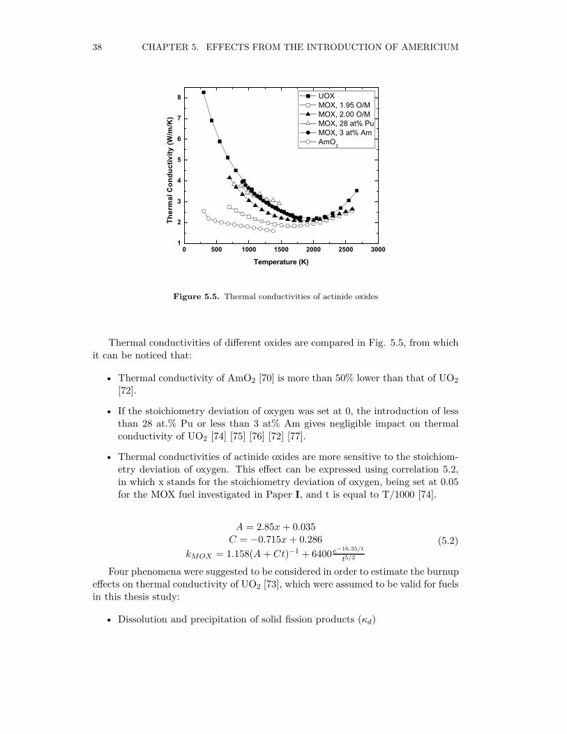
Thermal conductivities of different oxides are compared in Fig. 5.5, from whichit can be noticed that:
• Thermal conductivity of AmO2 [70] is more than 50% lower than that of UO2
[72].
• If the stoichiometry deviation of oxygen was set at 0, the introduction of lessthan 28 at.% Pu or less than 3 at% Am gives negligible impact on thermalconductivity of UO2 [74] [75] [76] [72] [77].
• Thermal conductivities of actinide oxides are more sensitive to the stoichiom-etry deviation of oxygen. This effect can be expressed using correlation 5.2,in which x stands for the stoichiometry deviation of oxygen, being set at 0.05for the MOX fuel investigated in Paper I, and t is equal to T/1000 [74].
A = 2.85x + 0.035C = −0.715x + 0.286
kMOX = 1.158(A + Ct)−1 + 6400e−16.35/t
t5/2
(5.2)
Four phenomena were suggested to be considered in order to estimate the burnupeffects on thermal conductivity of UO2 [73], which were assumed to be valid for fuelsin this thesis study:
• Dissolution and precipitation of solid fission products (κd)
5.2. EFFECTS ON THERMOPHYSICAL PROPERTIES 39
• Fission gas bubbles and pores (κp)
• Stoichiometric deviation (κx)
• Radiation damage induced circumferential cracks (κr)
κd and κp are dependent on the burnup and could be expressed into Eq. 5.3and Eq. 5.4, in which T is in Kelvin and B is in at%.
ω = 1.09 B3.265 + 0.0643(T/B)1/2
κd = ω[arctan(1/ω)](5.3)
κp = 1 +0.019B
(3− 0.019B)[1 + e−(T−1200)/100](5.4)
Nitride fuel
Correlations for thermal conductivities of different actinide nitrides were provided byArai [78] [79], Basini [83] and Nishi [81] as shown in Fig. 5.6. It can be noticed thatthermal conductivities of UN, NpN and PuN are around 150%, 60% and 30% higherthan that of AmN. Besides, as a chemical stablizer with high thermal conductivity,the introduction of 75 at% ZrN may increase the thermal conductivity of (Pu,Zr)Nby more than 80%. Thus, thermal conductivity of (Ac,Zr)N can be simply calculatedbased on Eq. 5.5, in which c and k stand for atomic fractions of actinides in fueland thermal conductivities of different actinide nitrides.
k(Np,Pu,Am,Zr)N = c(Np)k(NpN) + c(Pu)k(PuN)
+ c(Am)k(AmN) + c(Zr)k(ZrN) (5.5)
In order to estimate the burn up effect on thermal conductivity of nitride fuel,porosity build up was considered [82] by introducing Maxwell-Eucken correctionas expressed in Eq. 5.6, in which P is porosity and β equals 2.00 for (Pu,Zr)N[83]. Irradiation swelling rate of UN can be calculated based on Eq. 5.7, in whichTfuel,ave, Bu and ρ stand for the average fuel temperature in Kelvin, the fuel burnupin at.% and the as-fabricated fuel density in % theoritical density (TD) respectively[84]. This correlation is proved to be valid for (U,Pu)N based on results obtainedfrom irradiation experiments performed in JOYO [85]. Thus, it is also assumed tobe valid for fuel discussed in Paper II.
k = k01− P
1 + Pβ(5.6)
∆V/V (%) = 4.7× 10⁻¹¹T 3.12fuel,aveBu
0.83ρ0.5 (5.7)
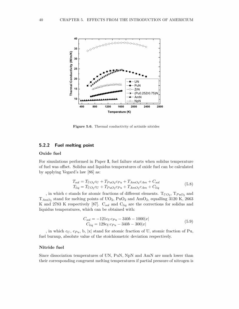
40 CHAPTER 5. EFFECTS FROM THE INTRODUCTION OF AMERICIUM
400 800 1200 1600 2000 2400 2800
10
15
20
25
30
35
40
Ther
mal
Con
duct
ivity
(W/m
/K)
Temperature (K)
UN PuN ZrN (Pu0.25Zr0.75)N AmN NpN
Figure 5.6. Thermal conductivity of actinide nitrides
5.2.2 Fuel melting point
Oxide fuel
For simulations performed in Paper I, fuel failure starts when solidus temperatureof fuel was offset. Solidus and liquidus temperatures of oxide fuel can be calculatedby applying Vegard’s law [86] as:
Tsol = TUO2cU + TPuO2
cPu + TAmO2cAm + Csol
Tliq = TUO2cU + TPuO2
cPu + TAmO2cAm + Cliq
(5.8)
, in which c stands for atomic fractions of different elements. TUO2, TPuO2
andTAmO2
stand for melting points of UO2, PuO2 and AmO2, equalling 3120 K, 2663K and 2783 K respectively [87]. Csol and Cliq are the corrections for solidus andliquidus temperatures, which can be obtained with:
Csol = −121cU cPu − 340b − 1000|x|Cliq = 129cU cPu − 340b − 300|x|
(5.9)
, in which cU , cPu, b, |x| stand for atomic fraction of U, atomic fraction of Pu,fuel burnup, absolute value of the stoichiometric deviation respectively.
Nitride fuel
Since dissociation temperatures of UN, PuN, NpN and AmN are much lower thantheir corresponding congruent melting temperatures if partial pressure of nitrogen is
5.2. EFFECTS ON THERMOPHYSICAL PROPERTIES 41
600 800 1000 1200 1400 1600 1800 2000 2200 240070
80
90
100
110
120
130
Hea
t Cap
acity
(J/m
ol/K
)
Temperature (K)
UO2
(U0.75
Pu0.25
)O1.98
PuO2
AmO2
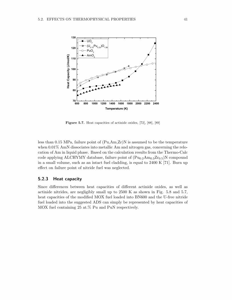
Figure 5.7. Heat capacities of actinide oxides, [72], [88], [89]
less than 0.15 MPa, failure point of (Pu,Am,Zr)N is assumed to be the temperaturewhen 0.01% AmN dissociates into metallic Am and nitrogen gas, concerning the relo-cation of Am in liquid phase. Based on the calculation results from the Thermo-Calccode applying ALCHYMY database, failure point of (Pu0.2Am0.3Zr0.5)N compoundin a small volume, such as an intact fuel cladding, is equal to 2400 K [71]. Burn upeffect on failure point of nitride fuel was neglected.
5.2.3 Heat capacity
Since differences between heat capacities of different actinide oxides, as well asactinide nitrides, are negligibly small up to 2500 K as shown in Fig. 5.8 and 5.7,heat capacities of the modified MOX fuel loaded into BN600 and the U-free nitridefuel loaded into the suggested ADS can simply be represented by heat capacities ofMOX fuel containing 25 at.% Pu and PuN respectively.

42 CHAPTER 5. EFFECTS FROM THE INTRODUCTION OF AMERICIUM
200 400 600 800 1000 1200 1400 1600 180045
50
55
60
65
70
Hea
t Cap
acity
(J/m
ol/K
)
Temperature (K)
UN (U
0.80,Pu
0.20)N
PuN AmN
Figure 5.8. Heat capacities of actinide nitrides, [90], [91], [70]
Chapter 6
Transient simulation results anddiscussion
6.1 Summary of transient simulation results
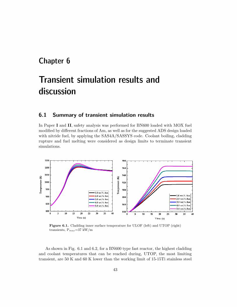
In Paper I and II, safety analysis was performed for BN600 loaded with MOX fuelmodified by different fractions of Am, as well as for the suggested ADS design loadedwith nitride fuel, by applying the SAS4A/SASSYS code. Coolant boiling, claddingrupture and fuel melting were considered as design limits to terminate transientsimulations.
Figure 6.1. Cladding inner surface temperature for ULOF (left) and UTOP (right)transients, Pmax=37 kW/m
As shown in Fig. 6.1 and 6.2, for a BN600 type fast reactor, the highest claddingand coolant temperatures that can be reached during, UTOP, the most limitingtransient, are 50 K and 60 K lower than the working limit of 15-15Ti stainless steel
43
44 CHAPTER 6. TRANSIENT SIMULATION RESULTS AND DISCUSSION
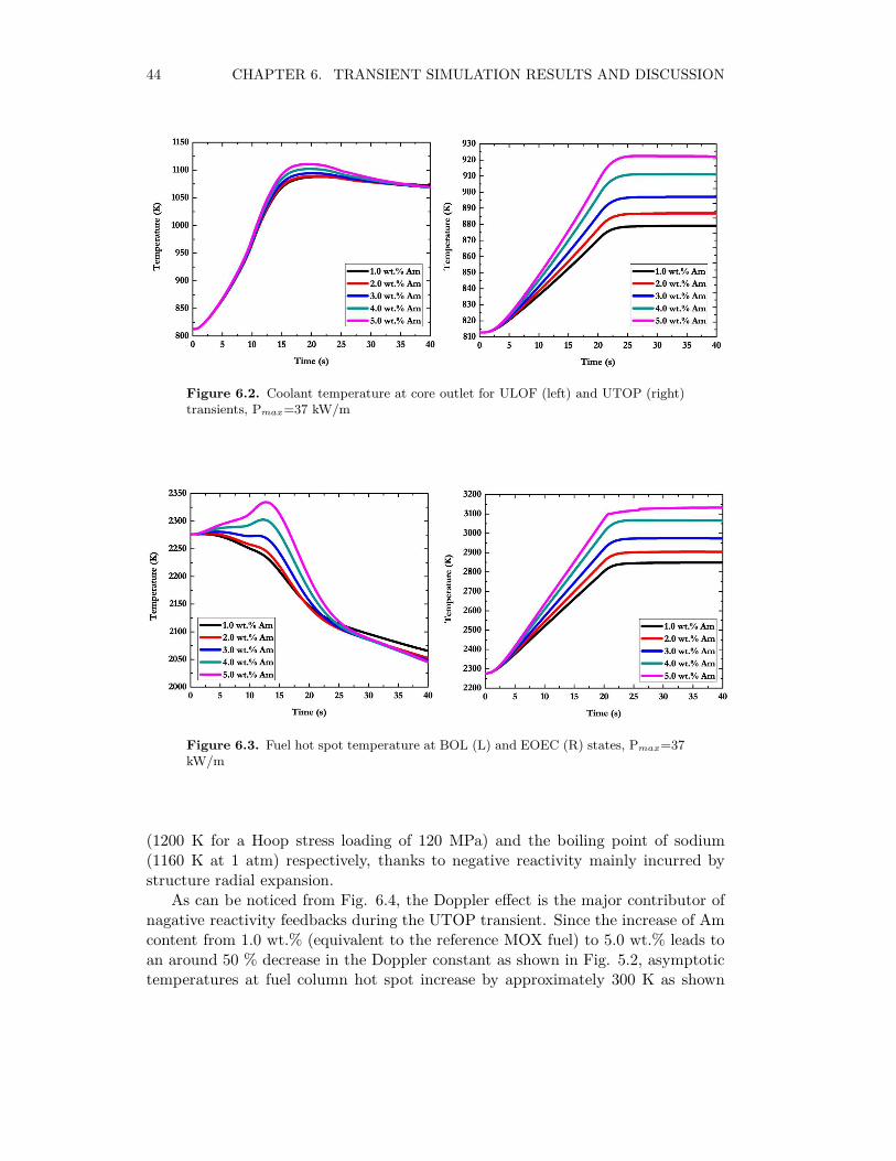
Figure 6.2. Coolant temperature at core outlet for ULOF (left) and UTOP (right)transients, Pmax=37 kW/m
Figure 6.3. Fuel hot spot temperature at BOL (L) and EOEC (R) states, Pmax=37kW/m
(1200 K for a Hoop stress loading of 120 MPa) and the boiling point of sodium(1160 K at 1 atm) respectively, thanks to negative reactivity mainly incurred bystructure radial expansion.
As can be noticed from Fig. 6.4, the Doppler effect is the major contributor ofnagative reactivity feedbacks during the UTOP transient. Since the increase of Amcontent from 1.0 wt.% (equivalent to the reference MOX fuel) to 5.0 wt.% leads toan around 50 % decrease in the Doppler constant as shown in Fig. 5.2, asymptotictemperatures at fuel column hot spot increase by approximately 300 K as shown
6.2. AM TRANSMUTATION CAPABILITIES 45
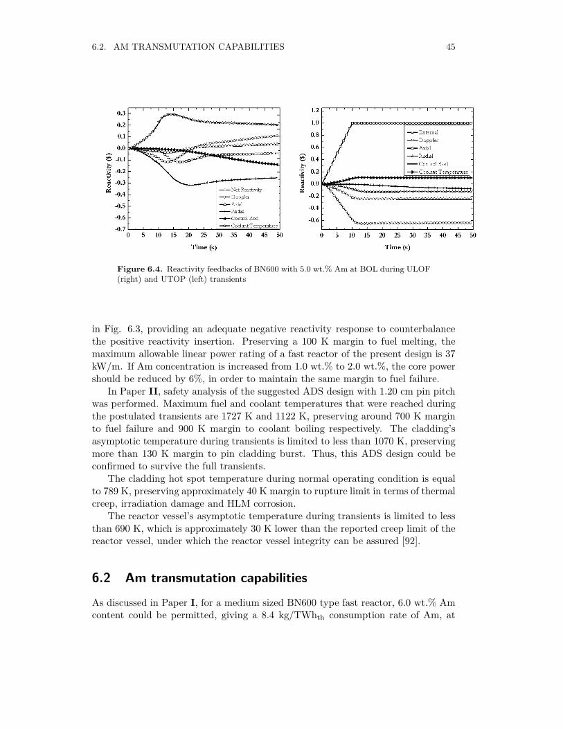
Figure 6.4. Reactivity feedbacks of BN600 with 5.0 wt.% Am at BOL during ULOF(right) and UTOP (left) transients
in Fig. 6.3, providing an adequate negative reactivity response to counterbalancethe positive reactivity insertion. Preserving a 100 K margin to fuel melting, themaximum allowable linear power rating of a fast reactor of the present design is 37kW/m. If Am concentration is increased from 1.0 wt.% to 2.0 wt.%, the core powershould be reduced by 6%, in order to maintain the same margin to fuel failure.
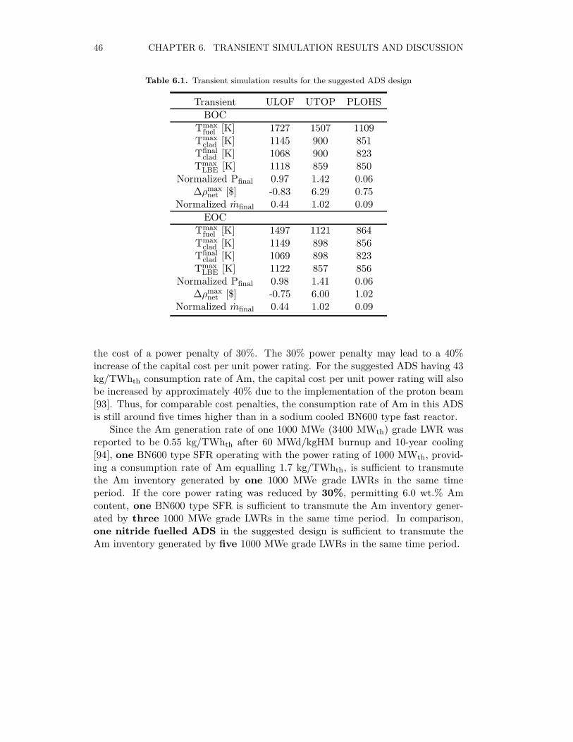
In Paper II, safety analysis of the suggested ADS design with 1.20 cm pin pitchwas performed. Maximum fuel and coolant temperatures that were reached duringthe postulated transients are 1727 K and 1122 K, preserving around 700 K marginto fuel failure and 900 K margin to coolant boiling respectively. The cladding’sasymptotic temperature during transients is limited to less than 1070 K, preservingmore than 130 K margin to pin cladding burst. Thus, this ADS design could beconfirmed to survive the full transients.
The cladding hot spot temperature during normal operating condition is equalto 789 K, preserving approximately 40 K margin to rupture limit in terms of thermalcreep, irradiation damage and HLM corrosion.
The reactor vessel’s asymptotic temperature during transients is limited to lessthan 690 K, which is approximately 30 K lower than the reported creep limit of thereactor vessel, under which the reactor vessel integrity can be assured [92].
6.2 Am transmutation capabilities
As discussed in Paper I, for a medium sized BN600 type fast reactor, 6.0 wt.% Amcontent could be permitted, giving a 8.4 kg/TWhth consumption rate of Am, at
46 CHAPTER 6. TRANSIENT SIMULATION RESULTS AND DISCUSSION
Table 6.1. Transient simulation results for the suggested ADS design
Transient ULOF UTOP PLOHS
BOC
Tmaxfuel [K] 1727 1507 1109
Tmaxclad [K] 1145 900 851
Tfinalclad [K] 1068 900 823
TmaxLBE [K] 1118 859 850
Normalized Pfinal 0.97 1.42 0.06∆ρmax
net [$] -0.83 6.29 0.75Normalized mfinal 0.44 1.02 0.09
EOC
Tmaxfuel [K] 1497 1121 864
Tmaxclad [K] 1149 898 856
Tfinalclad [K] 1069 898 823
TmaxLBE [K] 1122 857 856
Normalized Pfinal 0.98 1.41 0.06∆ρmax
net [$] -0.75 6.00 1.02Normalized mfinal 0.44 1.02 0.09
the cost of a power penalty of 30%. The 30% power penalty may lead to a 40%increase of the capital cost per unit power rating. For the suggested ADS having 43kg/TWhth consumption rate of Am, the capital cost per unit power rating will alsobe increased by approximately 40% due to the implementation of the proton beam[93]. Thus, for comparable cost penalties, the consumption rate of Am in this ADSis still around five times higher than in a sodium cooled BN600 type fast reactor.
Since the Am generation rate of one 1000 MWe (3400 MWth) grade LWR wasreported to be 0.55 kg/TWhth after 60 MWd/kgHM burnup and 10-year cooling[94], one BN600 type SFR operating with the power rating of 1000 MWth, provid-ing a consumption rate of Am equalling 1.7 kg/TWhth, is sufficient to transmutethe Am inventory generated by one 1000 MWe grade LWRs in the same timeperiod. If the core power rating was reduced by 30%, permitting 6.0 wt.% Amcontent, one BN600 type SFR is sufficient to transmute the Am inventory gener-ated by three 1000 MWe grade LWRs in the same time period. In comparison,one nitride fuelled ADS in the suggested design is sufficient to transmute theAm inventory generated by five 1000 MWe grade LWRs in the same time period.
Chapter 7
Conclusions
The upper limit to the amount of Am that can be loaded into a medium sized sodiumcooled fast reactor was once reported as 2-3%. However, after performing transientanalysis with the SAS4A/SASSYS code for BN600 fully loaded with MOX fuel, nosolid limit was found. Instead, we could show that a 6% power penalty is requiredwhen Am content was raised from 1% to 2%. If linear power rating could be furtherreduced, it is feasible introduce more Am, permitting a higher Am transmutationrate.
Based on safety performance evaluations made with the SAS4A/SASSYS code,the suggested ADS design with 1.20 cm pin pitch, providing a MA transmutationrate of 42 kg/TWhth, could survive the full set of transients, thanks to switching thecladding material from the reference T91 stainless steel to the austenitic 15/15Tistainless steel.
One nitride fuelled ADS with the power rating of 201 MWth and the consump-tion rate of Am equalling 43 kg/TWhth is sufficient to transmute the Am inventorygenerated by five 1000 MWe grade LWRs within the same operating time. Incomparison with the suggested ADS design, the BN600 type SFR with the samecost penalty can only transmute the Am inventory generated by three 1000 MWegrade LWRs within the same operating time. Therefore, it can be demostrated thatthe suggested ADS design is still more efficient for transmuting Am comparing tomedium sized sodium-cooled fast reactors fully loaded with MOX fuel.
47


Bibliography
[1] Jean-Pierre Revol, An accelerator-driven system for the destruction of nuclearwaste, Progress in Nuclear Energy, 38(1-2): 153-166, 2001.
[2] D. G. Foster et al., Review of PNL Study on Transmutation Processing of HighLevel Waste, LA-UR-74-74, Los Alamos Scientific Laboratory, 1974.
[3] IAEA, Country Waste Profile Report for Hungary, 2005.
[4] U.S. Nuclear Regulatory Commission, Radioactive Waste: Production, Storage,Disposal, NUREG/BR-0216, 2002.
[5] K. Kawashima, K. Kobayashi, K. Kaneto, Utilization of fast reactor excessneutrons for burning long lived fission products, Progress in Nuclear Energy,29(1): 281-288, 1995.
[6] Hüseyin Yapici, Gamze Genc, Nesrin Demir, A comprehensive study on neu-tronics of a lead-bismuth eutectic cooled accelerator-driven sub-critical systemfor long-lived fission product transmutation, Annals of Nuclear Energy, 35(7):1264-1273, 2008.
[7] Daniel Westlén, Reducing radiotoxicity in the long run , Progress in NuclearEnergy, 49(8):597-605, 2007.
[8] I. C. Gauld and B. D. Murphy, Oak Ridge National Laboratory (ORNL), Tech-nical basis for a proposed expansion of regulatory guide 3.54-decay heat gen-eration in an independent spent fuel storage installation, NUREG/CR-6999,ORNL/TM-2007/231, 2010.
[9] M. Delpech et al, Nuclear Technology-Bridging the Millennia, Proc. Int. Conf.Global 1999, Wyoming.
[10] P. E. Spivak, et al., Measurements of η, for U233, U235 and Pu239 with Neu-trons in the Energy Range 30 to 900 keV, Journal Nuclear Energy, 4:79-85,1957.
[11] Massimo Salvatores, Transmutation: Issues, Innovative options and Perspec-tives, Progress in Nuclear Energy, 40(3-4):375-402, 2002.
49
50 BIBLIOGRAPHY
[12] M. Tsirlin, S. Lesin and H. Branover, The selective corrosion of type 316 stain-less steel in molten lead, Journal of Material Science Letters, 14:1476-1478,1995.
[13] Vaidehi Ganesana, and Vedaraman Ganesan, Corrosion of annealed AISI 316stainless steel in sodium environment, Journal of Nuclear Materials, 256(1):69-77, 1998.
[14] Mamoru Konomur and Masakazu Ichimiya, Design Challenges for SodiumCooled Fast reactors, Journal of Nuclear Materials, 371(1-3):250-269, 2007.
[15] Nuclear Power Technology Development Section (IAEA), Fast ReactorDatabase, IAEA-TECDOC-866, pp. 22-26, 1996.
[16] Jinsuo Zhang, A review of steel corrosion by liquid lead and leadŰbismuthnextterm, Corrosion Science, 51(6):1207-1227, 2009.
[17] E. E. Shpil’rain, et al., Density and Thermal Expansion of Liquid Alkali Metals,in Handbook of Thermodynamic and Transport Properties of Alkali Metals,Blackwell Science Publications, Boston, 1985.
[18] J. K. Fink, Results of Cursory Literature Review on Lead Thermophysical Prop-erties, ANL Intra-Laboratory Memo, 1998.
[19] L.H. Martin and K. C. Lang, The thermal conductivity of water, Proceedingsof the Physical Society, 45(4): 523-529.
[20] K. Buksha et al., Operation experience of the BN-600 fast reactor, NuclearEngineering and Design, 173(1-3): 67-79, 1997.
[21] V. Cherny et al., Research Co-ordination Meeting on ”Updated Codes and Meth-ods to Reduce the Calculational Uncertainties of Liquid Metal Fast ReactorReactivity Effects”, IAEA-RC-803.2, TWG-FR/103, Vienna, Austria, pp. 304-337, 2000.
[22] A. Danilytchev et al., Reactivity Coefficients in Test Model IAEA (Phase 4),IAEA-RC-803.4, TWG-FR/113, Obninsk, Russia, pp. 245-271, 2003.
[23] S. I. Porollo et al., Swelling and microstructure of austenitic stainless steelChS-68 CW after high dose neutron irradiation, Journal of Nuclear Materials,393(1): 61-66, 2009.
[24] Alan E. Waltar and Albert B. Reynolds, Fast Breeder Reactors, PergamonPress, pp. 776-779, 1981.
[25] U.S. Department of Energy, Grand Junction Office, Statistical data of the ura-nium industry, GJO-100(82), 1983.
BIBLIOGRAPHY 51
[26] TRADETECH, The source for uranium price and industrial news since 1968,http://www.uranium.info/
[27] Kiyoto Aizawa, Consideration on safety research strategy toward commercial-ization of FBRs, Progress in Nuclear Energy, 32(3-4):255-262, 1998.
[28] B. F. Gromov et al., Designing the reactor installation with lead-bismuth coolantfor nuclear submarines, Proceedings of the conference "Heavy liquid metalcoolants in nuclear technology", pp. 14-17, 1998.
[29] S. Z. Verhovodko and V. V. Zamukov, The experience of designing, using andutilizing the nuclear power installations with lead-bismuth liquid metal coolantfor the "Alpha" type nuclear submarines, Proceedings of the conference "Heavyliquid metal coolants in nuclear technology", pp. 18-23, 1998.
[30] H. U. Wider, J. Carsson and E. Loewen, Renewed Interest in Lead Cooled FastReactors, Progress in Nuclear Energy, Vol. 47, No. 1-4, pp. 44-52, 2005.
[31] Giacomino Bandini, Paride Meloni and Massimiliano Polidori, Thermal-hydraulics analyses of ELSY lead fast reactor with open square core option,Nuclear Engineering and Design, Article in Press, Corrected Proof
[32] Allen L. Johnson et al., Spectroscopic and microscopic investigation of the cor-rosion of 316/316L stainless steel by leadŰbismuth eutectic (LBE) at elevatedtemperatures: importance of surface preparation, Journal of Nuclear Materials,328(2-3):88-96, 2004.
[33] B.F. Gromov, Y.I. Orlov, P.N. Martynov, V.A. Gulevskiy, The problems oftechnology of the heavy liquid metal coolants (lead-bismuth, lead), Proceedingsof the Conference of the Heavy Liquid Metal Coolants in Nuclear Technology,Obninsk, Russian Federation, pp. 87-100, 1998.
[34] Nuclear Energy Angency (NEA), Handbook on lead-bismuth eutectic alloy andlead properties, materials compatibility, thermal-hydraulics and technologies,Chapter 4, pp. 130-135, 2007.
[35] A. Ide, Y. Takenakat and S. Maeda, A study on utilization of heat of hightemperature gas-cooled reactors, Progress in Nuclear Energy, 29:201-208, 1995.
[36] T.D. Newton and P.J. Smith, Flexibility of the Gas Cooled Fast Reactor to Meetthe Requirements of the 21st Century, Gen-IV International Forum (GIF).
[37] P. Anzieu, R. Stainsby and K. Mikityuk, Gas-cooled fast reactor (GFR):overview and perspectives, GIF Symposium, Paris (France), 2009.
[38] Helge Petersen, Danish Atomic Energy Commission, The properties of helium:density, specific heats, viscosity, and thermal conductivity at pressures from 1to 100 bar and from room temperature to about 1800 K, Chapter 1, pp. 6-7,1970.

52 BIBLIOGRAPHY
[39] G. Melese-d’Hospital and R.H. Simon, Status of gas-cooled fast breeder reactorprograms, Nuclear Engineering and Design, 40:5-12, 1977.
[40] M. Salvatores, and G. Palmiotti, Radioactive waste partitioning and transmu-tation within advanced fuel cycles: achievements and challenges, Progress inParticle and Nuclear Physics, Article in Press.
[41] J. Tommasi et al., Long-lived waste transmutation in reactors, Nuclear Tech-nology, 111:133-148, 1995.
[42] M. A. Smith, E.E. Morris and R.N. Hill, Physics and safety studies of lowconversion ratio sodium cooled fast reactors, Proc. Int. Conf. GLOBAL 2003,New Orleans, 2003.
[43] C. Fazio et al., Advanced nuclear fuel cycles and systems, Proc. Int. Conf.Global 2007, Idaho, 2007.
[44] Kamil Tuček, Johan Carlssona and Hartmut Widera, Nuclear Engineering andDesign, 236(14-16):1589-1598, 2006.
[45] Alan Baxter and Carmelo Rodriguez, The application of gas-cooled reactortechnologies to the transmutation of nuclear waste, Progress in Nuclear Energy,38(1-2):81-105, 2001.
[46] A.V. Dementyev, N.M. Sobolevsky, Yu.Ya. Stavissky, Neutron yield from ex-tended lead target under incident protons of 0.1 to 100 GeV, Nuclear Instru-ments and Methods in Physics Research A, 374: 70-72, 1996.
[47] J. Ales et al., XX International Linac Conference, BNL-6742.6, 2000.
[48] Nam-il Tak, Hans-Joachim Neitzel and Xu Cheng, Computational fluid dynam-ics analysis of spallation target for experimental accelerator-driven transmuta-tion system, Nuclear Engineering and Design, 235(7): 761-772, 2005.
[49] F. Sordo et al., Material selection for spallation neutron source windows: Ap-plication to PDS-XADS and XT-ADS prototypes, Nuclear Engineering and De-sign, 239(11): 2573-2580, 2009.
[50] P. Seltborg, J. Wallenius, K. Tucek and W.Gudowski, Definition and applica-tion of proton source efficiency in accelerator driven systems, Nuclear Scienceand Engineering, 145:390-399, 2003.
[51] Andrei Fokau et al., A source efficient ADS for minor actinides burning, Annalsof Nuclear Energy, 37(4):540-545, 2010.
[52] R. Calabrese et al., Heterogeneous fuels for minor actinides transmutation:Fuel performance codes predictions in the EFIT case study , Annals of NuclearEnergy, 37(6): 867-874, 2010.
BIBLIOGRAPHY 53
[53] J. Leppänen, PSG2 / Serpent a Continuous-energy Monte Carlo ReactorPhysics Burnup Calculation Code, Methodology-User’s Manual-Validation Re-port, 2008.
[54] J. Leppänen, Diffusion Code Group Constant Generation Using the MonteCarlo Method, In Proc. XII Meeting on Reactor Physics in the Nordic Coun-tries, Halden, 2005.
[55] J. E. Cahalan, SAS4A/SASSYS-1 Maintenance and Operations Handbook,Argonne National Laboratory, Oct. 2002.
[56] M. Eriksson, J. E. Cahalan and W. S. Yang, On the Performance of PointKinetics for the Analysis of Accelerator-Driven Systems, Nuclear Science andEngineering, 149(3): 298-311, 2005.
[57] Nuclear Power Technology Development Section, Transient and Accident Anal-ysis of a BN-800 Type LMFR with near Zero Void Effect, IAEA-TECDOC-1139, 2000.
[58] O. M. Saraev, et al., Technical Committee Meeting, IAEA-TECDOC-907,Kalpakkam (1996), 27-31.
[59] W. Maschek et al., Safety and design concepts of the 400 MWth-class EFITaccelerator driven transmuter and considerations for further developments, En-ergy Conversion and Management, Article in Press, 2010.
[60] M. Petrazzini, EFIT fuel assembly pressure drop, EUROTRANS Technical Re-port.
[61] W. Maschek et al., Accelerator driven systems for transmutation: Fuel develop-ment, design and safety, Progress in Nuclear Energy, 50(2-6): 333-340, 2008.
[62] Kenneth Barbalace. Periodic Table of Elements. EnvironmentalChemistry.com,1995-2010, http://EnvironmentalChemistry.com/yogi/periodic/Am.html
[63] David R. Lide, 89th Handbook of Chemistry and Physics, Taylor&Francis Inc.,2008-2009.
[64] Pradyot Patnaik, Handbook of Inorganic Chemicals, McGraw-Hill Professional,2003.
[65] M. Salvatores et al., Intercomparison of systems for TRU recycle at equilibrium,Proc. Int. Conf. GLOBAL 2005.
[66] Youpeng Zhang and Janne Wallenius, Transmutation of americium in amedium size sodium cooled fast reactor design, Annals of Nuclear Energy, 2010.
[67] P. del Marmol, Delayed-neutron precursors, Atomic Data and Nuclear DataTables, 6(2): 141-151, 1969.

54 BIBLIOGRAPHY
[68] E. H. P. Cordfunke et al., Thermochemical Data for Reactor Materials andFission Products, Elsevier, Amsterdam, 1990.
[69] H. E. Schmidt, In: Proceedings of the 4th Journees d’Actinides, AERE-R-7961, Harwell, UK, 1975.
[70] Tsuyoshi Nishi et al., Thermal conductivity of AmO2−x, Journal of NuclearMaterials, 373(1-3):295-298, 2008.
[71] M. Eriksson, J. Wallenius, M. Jolkkonen, J. Cahalan, Inherent safety of fuelsfor accelerator-driven systems, 151(3): 314-333, 2005.
[72] J. K. Fink, Thermophysical properties of uranium dioxide, Journal of NuclearMaterials, 279(1): 1-18, 2000.
[73] P. G. Lucuta, Hj. Matzke and J. Hastings, A pragmatic approach to mod-elling thermal conductivity of irradiated UO2 fuel: review and recommenda-tions, Journal of Nuclear Materials, 232(2-3): 166-180, 1996.
[74] C. Duriez et al., Thermal conductivity of hypostoichiometric low Pu content(U,Pu)O2−x mixed oxide, Journal of Nuclear Materials, 277(2-3): 143-158,2000.
[75] P. R. Vasudeva Rao et al,Oxygen potential and thermal conductivity of (U, Pu)mixed oxides, Journal of Nuclear Materials, 348(3):329-334, 2006.
[76] Masato Kato and Kenji Konashi, Lattice parameters of (U, Pu, Am, Np)O2−x,Journal of Nuclear Materials, 385(1): 117-121, 2009.
[77] Kyoichi Morimoto et al,Thermal conductivities of (U, Pu, Am)O2 solid solu-tions, Journal of Alloys and Compounds, 452(1): 54-60, 2008.
[78] Y. Arai et al., Dependence of the thermal conductivity of (U, Pu) N on porosityand plutonium content, Journal of Nuclear Materials, 195(1-2): 37-43, 1992.
[79] Yasuo Arai et al., Thermal conductivity of neptunium mononitride from 740 to1600 K, Journal of Nuclear Materials, 211(3): 248-250, 1994.
[80] V. Basini et al., Experimental assessment of thermophysical properties of (Pu,Zr)N, Journal of Nuclear Materials, 344(1-3): 186-190, 2005.
[81] Tsuyoshi Nishi et al., Thermal diffusivity of Americium mononitride from 373to 1473 K, Journal of Nuclear Materials, 355(1-3): 114-118, 2006.
[82] Yeon Soo Kim, G.L Hofman, S.L Hayes and Y.H Sohn, Constituent redistribu-tion in UŰPuŰZr fuel during irradiation, Journal of Nuclear Materials, 327(1):27-36, 2004.
BIBLIOGRAPHY 55
[83] V. Basini, J. P. Ottaviani, J. C. Richaud, M. Streitb and F. Ingold, Experimen-tal assessment of thermophysical properties of (Pu,Zr)N, Journal of NuclearMaterials, 344(1-3): 186-190, 2005.
[84] Steven B. Ross, Mohamed S. El-Genk and R.Bruce Matthews, Uranium nitridefuel swelling correlation, Journal of Nuclear Materials, 170(2): 169-177, 1990.
[85] Kosuke Tanaka, Koji Maeda, Kozo Katsuyama, Masaki Inoue, Takashi Iwaiand Yasuo Arai, Fission gas release and swelling in uraniumŰplutonium mixednitride fuels, Journal of Nuclear Materials, 327(2-3): 77-87, 2004.
[86] Roger Thetford and Mike Mignanelli, The chemistry and physics of modellingnitride fuels for transmutation, Journal of Nuclear Materials, 320(1-2): 44-53,2003.
[87] J.J. Katz, G.T. Seaborg and L.R. Morss, The chemistry of the actinide ele-ments, 2nd Edition, Vols. 1 and 2, Chapman and Hall, London 1986.
[88] R. L. Gibby et al., Analytical expressions for enthalpy and heat capacity foruranium-plutonium oxide, Journal of Nuclear Materials, 50(2): 155-161, 1974.
[89] C. Thiriet, R. J. M. Konings, Chemical thermodynamic representation ofAmO2−x, Journal of Nuclear Materials, 320(3): 292-298, 2003.
[90] T. Matsui and R.W. Ohse, Thermodynamic properties of uranium nitride, plu-tonium nitride and uranium-plutonium mixed nitride, High Temp-High Press19 (1987) 1.
[91] F. L. Oetting, The chemical thermodynamic properties of nuclear materials III.Plutonium mononitride, The Journal of Chemical Thermodynamics, 10(10):941-948, 1978.
[92] Giacomino Bandini et al., Decay Heat Removal and Transient Analysis in Ac-cidental Conditions in the EFIT Reactor, Science and Technology of NuclearInstallations, Volume 2008, Article ID 681847, 2008.
[93] US Department of Energy (DOE), A Roadmap for Developing Accelera-tor Transmutation of Waste (ATW) Technology - A Report to Congress,DOE/RW0519, 1999.
[94] Y. Ando, K. Nishihara, H. Takano, Estimation of spent fuel compositions fromlight water reactors, 37: 924-933, 2000.


Appendix A
SERPENT inputs
A.1 BN600 type sodium cooled fast reactor
pin 1fuel 0.295 % fuel pellet outer radiusvoid 0.305 % cladding inner radiusclad 0.345 % cladding outer radiussodium % coolant outside of clad%void
pin 2 % gas plenumvoid 0.305clad 0.345sodium%void
pin 12clad 0.345sodium
pin 5clad 0.600sodium
surf 4000 hexyc 0.0 0.0 0.40365surf 401 pz -226 % lower nozzelsurf 402 pz -152 % gas plenumsurf 403 pz -86.5 % lower blanketsurf 404 pz -51.5 % lower active zonesurf 405 pz 51.5 % upper active zonesurf 406 pz 81.5 % upper blanket
57
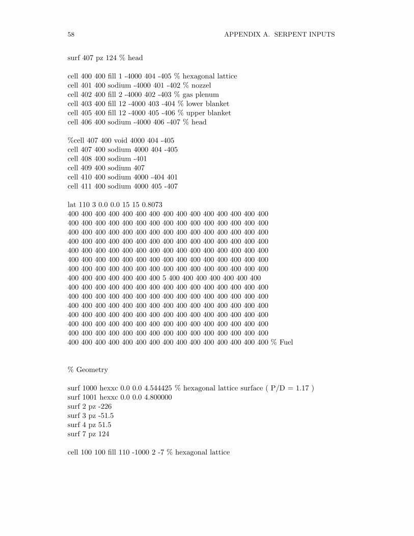
58 APPENDIX A. SERPENT INPUTS
surf 407 pz 124 % head
cell 400 400 fill 1 -4000 404 -405 % hexagonal latticecell 401 400 sodium -4000 401 -402 % nozzelcell 402 400 fill 2 -4000 402 -403 % gas plenumcell 403 400 fill 12 -4000 403 -404 % lower blanketcell 405 400 fill 12 -4000 405 -406 % upper blanketcell 406 400 sodium -4000 406 -407 % head
%cell 407 400 void 4000 404 -405cell 407 400 sodium 4000 404 -405cell 408 400 sodium -401cell 409 400 sodium 407cell 410 400 sodium 4000 -404 401cell 411 400 sodium 4000 405 -407
lat 110 3 0.0 0.0 15 15 0.8073400 400 400 400 400 400 400 400 400 400 400 400 400 400 400400 400 400 400 400 400 400 400 400 400 400 400 400 400 400400 400 400 400 400 400 400 400 400 400 400 400 400 400 400400 400 400 400 400 400 400 400 400 400 400 400 400 400 400400 400 400 400 400 400 400 400 400 400 400 400 400 400 400400 400 400 400 400 400 400 400 400 400 400 400 400 400 400400 400 400 400 400 400 400 400 400 400 400 400 400 400 400400 400 400 400 400 400 400 5 400 400 400 400 400 400 400400 400 400 400 400 400 400 400 400 400 400 400 400 400 400400 400 400 400 400 400 400 400 400 400 400 400 400 400 400400 400 400 400 400 400 400 400 400 400 400 400 400 400 400400 400 400 400 400 400 400 400 400 400 400 400 400 400 400400 400 400 400 400 400 400 400 400 400 400 400 400 400 400400 400 400 400 400 400 400 400 400 400 400 400 400 400 400400 400 400 400 400 400 400 400 400 400 400 400 400 400 400 % Fuel
% Geometry
surf 1000 hexxc 0.0 0.0 4.544425 % hexagonal lattice surface ( P/D = 1.17 )surf 1001 hexxc 0.0 0.0 4.800000surf 2 pz -226surf 3 pz -51.5surf 4 pz 51.5surf 7 pz 124
cell 100 100 fill 110 -1000 2 -7 % hexagonal lattice

A.1. BN600 TYPE SODIUM COOLED FAST REACTOR 59
cell 101 100 clad 1000 -1001 2 -7%cell 102 100 void 1001 3 -4cell 102 100 sodium 1001 3 -4cell 103 100 sodium 1001 4 -7cell 104 100 sodium 1001 2 -3cell 105 100 sodium -2cell 106 100 sodium 7
surf 2000 hexxc 0.0 0.0 4.80000cell 200 200 clad -1001 2 -7cell 201 200 sodium 1001 2 -7cell 202 200 sodium -2cell 203 200 sodium 7
cell 901 900 sodium -1001 2 -7cell 902 900 sodium 1001 2 -7cell 903 900 sodium -2cell 904 900 sodium 7
lat 300 2 0.0 0.0 27 27 9.9200 200 200 200 200 200 200 200 200 200 200 200 200 200 200 200 200 200 200 200200 200 200 200 200 200 200200 200 200 200 200 200 200 200 200 200 200 200 200 200 200 200 200 200 200 200200 200 200 200 200 200 200200 200 200 200 200 200 200 200 200 200 200 200 200 200 100 100 100 100 100 100100 100 100 100 200 200 200 200 200 200 200 200 200 200 200 200 200 200 200 100100 100 100 100 100 100 100 100 100 100 100 100 200 200 200 200 200 200 200 200200 200 200 200 200 100 100 100 100 100 100 100 100 100 100 100 100 100 100 200200 200 200 200 200 200 200 200 200 200 200 100 100 100 100 100 900 100 100 100900 100 100 100 100 100 200 200 200 200 200 200 200 200 200 200 200 100 100 100100 100 100 100 100 100 100 100 100 100 100 100 100 200 200 200 200 200 200 200200 200 200 100 100 100 900 100 100 100 100 900 100 100 100 100 900 100 100 100200 200 200 200 200 200 200 200 200 100 100 100 100 100 100 100 100 100 100 100100 100 100 100 100 100 100 200 200 200 200 200 200 200 200 100 100 100 100 100100 100 900 100 100 100 900 100 100 100 100 100 100 100 200 200 200 200 200 200200 100 100 100 100 100 900 100 100 100 100 100 100 100 100 900 100 100 100 100100 200 200 200 200 200 200 100 100 100 900 100 100 100 100 100 100 100 100 100100 100 100 100 900 100 100 100 200 200 200 200 200 100 100 100 100 100 100 100100 100 100 100 100 100 100 100 100 100 100 100 100 100 100 200 200 200 200 200100 100 100 100 100 100 900 100 100 100 900 100 100 100 900 100 100 100 100 100100 200 200 200 % hex mid200 200 100 100 100 100 100 100 100 100 100 100 100 100 100 100 100 100 100 100100 100 100 100 200 200 200 % 11200 200 100 100 100 900 100 100 100 100 100 100 100 100 100 100 100 100 100 900

60 APPENDIX A. SERPENT INPUTS
100 100 100 200 200 200 200 % 10200 200 100 100 100 100 100 900 100 100 100 100 100 100 100 100 900 100 100 100100 100 200 200 200 200 200 % 9200 200 100 100 100 100 100 100 100 900 100 100 100 900 100 100 100 100 100 100100 200 200 200 200 200 200 % 8200 200 100 100 100 100 100 100 100 100 100 100 100 100 100 100 100 100 100 100200 200 200 200 200 200 200 % 7200 200 100 100 100 900 100 100 100 100 900 100 100 100 100 900 100 100 100 200200 200 200 200 200 200 200 % 6200 200 100 100 100 100 100 100 100 100 100 100 100 100 100 100 100 100 200 200200 200 200 200 200 200 200 % 5200 200 100 100 100 100 100 900 100 100 100 900 100 100 100 100 100 200 200 200200 200 200 200 200 200 200 % 4200 200 100 100 100 100 100 100 100 100 100 100 100 100 100 100 200 200 200 200200 200 200 200 200 200 200 % 3200 200 100 100 100 100 100 100 100 100 100 100 100 100 100 200 200 200 200 200200 200 200 200 200 200 200 % 2200 200 200 100 100 100 100 100 100 100 100 100 100 200 200 200 200 200 200 200200 200 200 200 200 200 200 % 1200 200 200 200 200 200 200 200 200 200 200 200 200 200 200 200 200 200 200 200200 200 200 200 200 200 200 %200 200 200 200 200 200 200 200 200 200 200 200 200 200 200 200 200 200 200 200200 200 200 200 200 200 200 %
surf 3000 hexyc 0.0 0.0 98.59699surf 3001 hexyc 0.0 0.0 148.09699surf 3010 hexyc 0.0 0.0 157.99699surf 3002 cyl 0.0 0.0 207.0000surf 3003 cyl 0.0 0.0 210.0000surf 3004 pz -226surf 3005 pz 124surf 3008 pz -426surf 3009 pz 324
cell 300 0 fill 300 -3000 3004 -3005cell 301 0 clad 3000 -3001 3004 -3005cell 302 0 BC4 3001 -3010 3004 -3005cell 303 0 sodium 3010 -3002 3004 -3005cell 304 0 clad 3002 -3003 3004 -3005cell 305 0 clad -3003 -3004 3008cell 306 0 clad -3003 3005 -3009cell 308 0 outside -3008cell 309 0 outside 3009cell 310 0 outside 3003 3008 -3009
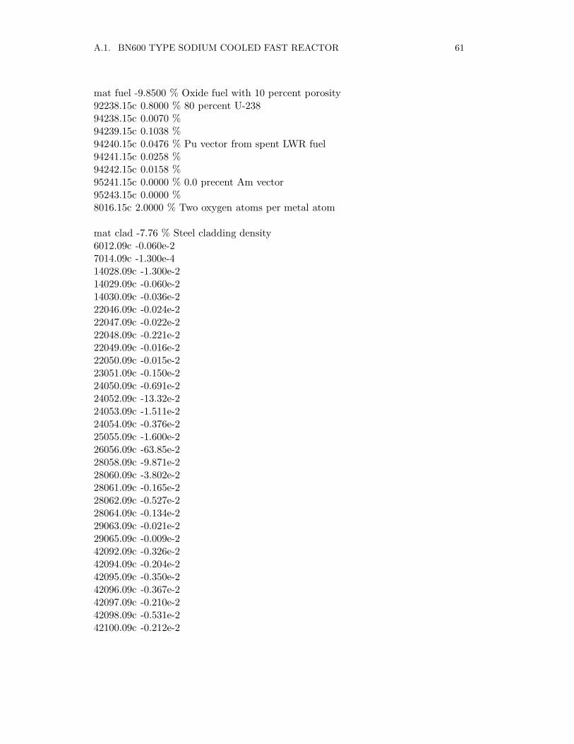
A.1. BN600 TYPE SODIUM COOLED FAST REACTOR 61
mat fuel -9.8500 % Oxide fuel with 10 percent porosity92238.15c 0.8000 % 80 percent U-23894238.15c 0.0070 %94239.15c 0.1038 %94240.15c 0.0476 % Pu vector from spent LWR fuel94241.15c 0.0258 %94242.15c 0.0158 %95241.15c 0.0000 % 0.0 precent Am vector95243.15c 0.0000 %8016.15c 2.0000 % Two oxygen atoms per metal atom
mat clad -7.76 % Steel cladding density6012.09c -0.060e-27014.09c -1.300e-414028.09c -1.300e-214029.09c -0.060e-214030.09c -0.036e-222046.09c -0.024e-222047.09c -0.022e-222048.09c -0.221e-222049.09c -0.016e-222050.09c -0.015e-223051.09c -0.150e-224050.09c -0.691e-224052.09c -13.32e-224053.09c -1.511e-224054.09c -0.376e-225055.09c -1.600e-226056.09c -63.85e-228058.09c -9.871e-228060.09c -3.802e-228061.09c -0.165e-228062.09c -0.527e-228064.09c -0.134e-229063.09c -0.021e-229065.09c -0.009e-242092.09c -0.326e-242094.09c -0.204e-242095.09c -0.350e-242096.09c -0.367e-242097.09c -0.210e-242098.09c -0.531e-242100.09c -0.212e-2
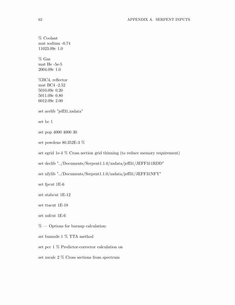
62 APPENDIX A. SERPENT INPUTS
% Coolantmat sodium -0.7411023.09c 1.0
% Gasmat He -5e-52004.09c 1.0
%BC4, reflectormat BC4 -2.525010.09c 0.205011.09c 0.806012.09c 2.00
set acelib "jeff31.xsdata"
set bc 1
set pop 4000 4000 30
set powdens 80.352E-3 %
set egrid 1e-4 % Cross section grid thinning (to reduce memory requirement)
set declib "../Documents/Serpent1.1.0/xsdata/jeff31/JEFF311RDD"
set nfylib "../Documents/Serpent1.1.0/xsdata/jeff31/JEFF31NFY"
set fpcut 1E-6
set stabcut 1E-12
set ttacut 1E-18
set xsfcut 1E-6
% — Options for burnup calculation:
set bumode 1 % TTA method
set pcc 1 % Predictor-corrector calculation on
set xscalc 2 % Cross sections from spectrum
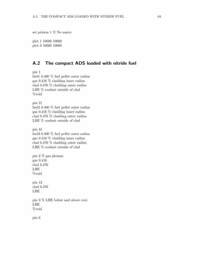
A.2. THE COMPACT ADS LOADED WITH NITRIDE FUEL 63
set printm 1 % No mater
plot 1 10000 10000plot 3 10000 10000
A.2 The compact ADS loaded with nitride fuel
pin 1fuel1 0.400 % fuel pellet outer radiusgas 0.416 % cladding inner radiusclad 0.476 % cladding outer radiusLBE % coolant outside of clad%void
pin 21fuel2 0.400 % fuel pellet outer radiusgas 0.416 % cladding inner radiusclad 0.476 % cladding outer radiusLBE % coolant outside of clad
pin 31fuel3 0.400 % fuel pellet outer radiusgas 0.416 % cladding inner radiusclad 0.476 % cladding outer radiusLBE % coolant outside of clad
pin 2 % gas plenumgas 0.416clad 0.476LBE%void
pin 12clad 0.476LBE
pin 3 % LBE below and above coreLBE%void
pin 6
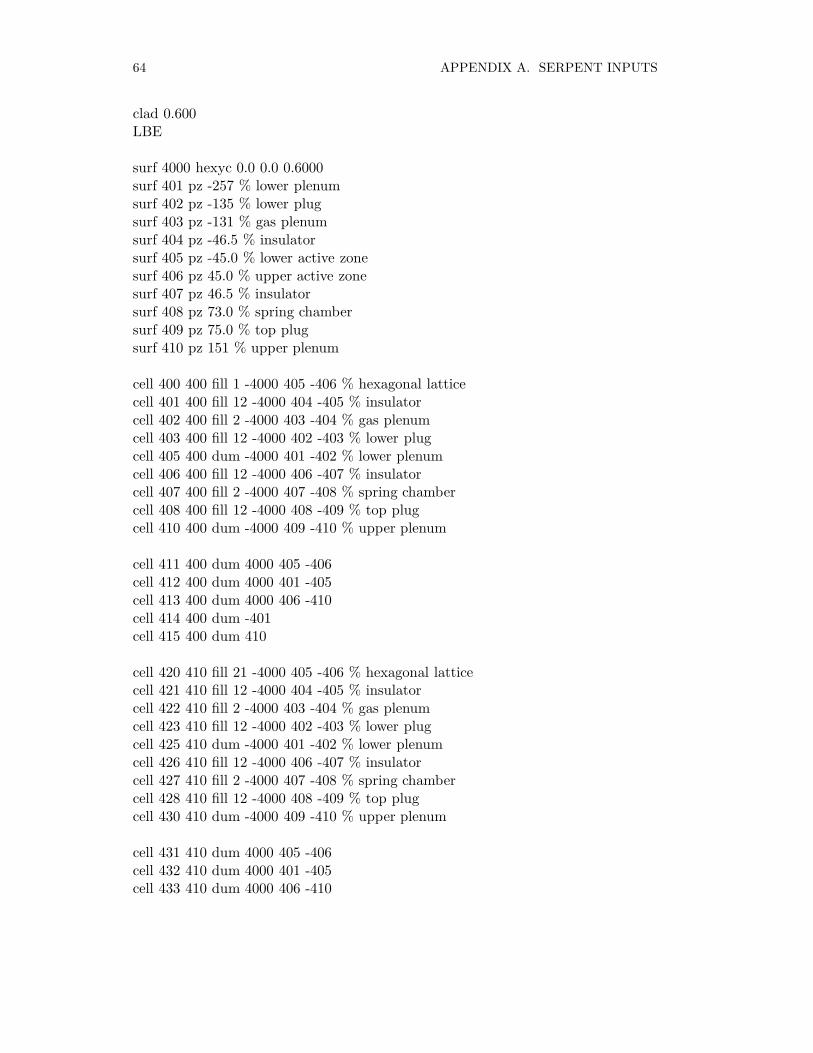
64 APPENDIX A. SERPENT INPUTS
clad 0.600LBE
surf 4000 hexyc 0.0 0.0 0.6000surf 401 pz -257 % lower plenumsurf 402 pz -135 % lower plugsurf 403 pz -131 % gas plenumsurf 404 pz -46.5 % insulatorsurf 405 pz -45.0 % lower active zonesurf 406 pz 45.0 % upper active zonesurf 407 pz 46.5 % insulatorsurf 408 pz 73.0 % spring chambersurf 409 pz 75.0 % top plugsurf 410 pz 151 % upper plenum
cell 400 400 fill 1 -4000 405 -406 % hexagonal latticecell 401 400 fill 12 -4000 404 -405 % insulatorcell 402 400 fill 2 -4000 403 -404 % gas plenumcell 403 400 fill 12 -4000 402 -403 % lower plugcell 405 400 dum -4000 401 -402 % lower plenumcell 406 400 fill 12 -4000 406 -407 % insulatorcell 407 400 fill 2 -4000 407 -408 % spring chambercell 408 400 fill 12 -4000 408 -409 % top plugcell 410 400 dum -4000 409 -410 % upper plenum
cell 411 400 dum 4000 405 -406cell 412 400 dum 4000 401 -405cell 413 400 dum 4000 406 -410cell 414 400 dum -401cell 415 400 dum 410
cell 420 410 fill 21 -4000 405 -406 % hexagonal latticecell 421 410 fill 12 -4000 404 -405 % insulatorcell 422 410 fill 2 -4000 403 -404 % gas plenumcell 423 410 fill 12 -4000 402 -403 % lower plugcell 425 410 dum -4000 401 -402 % lower plenumcell 426 410 fill 12 -4000 406 -407 % insulatorcell 427 410 fill 2 -4000 407 -408 % spring chambercell 428 410 fill 12 -4000 408 -409 % top plugcell 430 410 dum -4000 409 -410 % upper plenum
cell 431 410 dum 4000 405 -406cell 432 410 dum 4000 401 -405cell 433 410 dum 4000 406 -410

A.2. THE COMPACT ADS LOADED WITH NITRIDE FUEL 65
cell 434 410 dum -401cell 435 410 dum 410
cell 440 420 fill 31 -4000 405 -406 % hexagonal latticecell 441 420 fill 12 -4000 404 -405 % insulatorcell 442 420 fill 2 -4000 403 -404 % gas plenumcell 443 420 fill 12 -4000 402 -403 % lower plugcell 445 420 dum -4000 401 -402 % lower plenumcell 446 420 fill 12 -4000 406 -407 % insulatorcell 447 420 fill 2 -4000 407 -408 % spring chambercell 448 420 fill 12 -4000 408 -409 % top plugcell 450 420 dum -4000 409 -410 % upper plenum
%cell 451 420 void 4000 405 -406cell 451 420 dum 4000 405 -406cell 452 420 dum 4000 401 -405cell 453 420 dum 4000 406 -410cell 454 420 dum -401cell 455 420 dum 410
lat 110 3 0.0 0.0 19 19 1.20400 400 400 400 400 400 400 400 400 400 400 400 400 400 400 400 400 400 400400 400 400 400 400 400 400 400 400 400 400 400 400 400 400 400 400 400 400400 400 400 400 400 400 400 400 400 400 400 400 400 400 400 400 400 400 400400 400 400 400 400 400 400 400 400 400 400 400 400 400 400 400 400 400 400400 400 400 400 400 400 400 400 400 400 400 400 400 400 400 400 400 400 400400 400 400 400 400 400 400 400 400 400 400 400 400 400 400 400 400 400 400400 400 400 400 400 400 400 400 400 400 400 400 400 400 400 400 400 400 400400 400 400 400 400 400 400 400 400 400 400 400 400 400 400 400 400 400 400400 400 400 400 400 400 400 400 400 400 400 400 400 400 400 400 400 400 400400 400 400 400 400 400 400 400 400 6 400 400 400 400 400 400 400 400 400400 400 400 400 400 400 400 400 400 400 400 400 400 400 400 400 400 400 400400 400 400 400 400 400 400 400 400 400 400 400 400 400 400 400 400 400 400400 400 400 400 400 400 400 400 400 400 400 400 400 400 400 400 400 400 400400 400 400 400 400 400 400 400 400 400 400 400 400 400 400 400 400 400 400400 400 400 400 400 400 400 400 400 400 400 400 400 400 400 400 400 400 400400 400 400 400 400 400 400 400 400 400 400 400 400 400 400 400 400 400 400400 400 400 400 400 400 400 400 400 400 400 400 400 400 400 400 400 400 400400 400 400 400 400 400 400 400 400 400 400 400 400 400 400 400 400 400 400400 400 400 400 400 400 400 400 400 400 400 400 400 400 400 400 400 400 400 %Fuel 1
lat 120 3 0.0 0.0 19 19 1.20410 410 410 410 410 410 410 410 410 410 410 410 410 410 410 410 410 410 410410 410 410 410 410 410 410 410 410 410 410 410 410 410 410 410 410 410 410

66 APPENDIX A. SERPENT INPUTS
410 410 410 410 410 410 410 410 410 410 410 410 410 410 410 410 410 410 410410 410 410 410 410 410 410 410 410 410 410 410 410 410 410 410 410 410 410410 410 410 410 410 410 410 410 410 410 410 410 410 410 410 410 410 410 410410 410 410 410 410 410 410 410 410 410 410 410 410 410 410 410 410 410 410410 410 410 410 410 410 410 410 410 410 410 410 410 410 410 410 410 410 410410 410 410 410 410 410 410 410 410 410 410 410 410 410 410 410 410 410 410410 410 410 410 410 410 410 410 410 410 410 410 410 410 410 410 410 410 410410 410 410 410 410 410 410 410 410 6 410 410 410 410 410 410 410 410 410410 410 410 410 410 410 410 410 410 410 410 410 410 410 410 410 410 410 410410 410 410 410 410 410 410 410 410 410 410 410 410 410 410 410 410 410 410410 410 410 410 410 410 410 410 410 410 410 410 410 410 410 410 410 410 410410 410 410 410 410 410 410 410 410 410 410 410 410 410 410 410 410 410 410410 410 410 410 410 410 410 410 410 410 410 410 410 410 410 410 410 410 410410 410 410 410 410 410 410 410 410 410 410 410 410 410 410 410 410 410 410410 410 410 410 410 410 410 410 410 410 410 410 410 410 410 410 410 410 410410 410 410 410 410 410 410 410 410 410 410 410 410 410 410 410 410 410 410410 410 410 410 410 410 410 410 410 410 410 410 410 410 410 410 410 410 410 %Fuel 2
lat 130 3 0.0 0.0 19 19 1.20420 420 420 420 420 420 420 420 420 420 420 420 420 420 420 420 420 420 420420 420 420 420 420 420 420 420 420 420 420 420 420 420 420 420 420 420 420420 420 420 420 420 420 420 420 420 420 420 420 420 420 420 420 420 420 420420 420 420 420 420 420 420 420 420 420 420 420 420 420 420 420 420 420 420420 420 420 420 420 420 420 420 420 420 420 420 420 420 420 420 420 420 420420 420 420 420 420 420 420 420 420 420 420 420 420 420 420 420 420 420 420420 420 420 420 420 420 420 420 420 420 420 420 420 420 420 420 420 420 420420 420 420 420 420 420 420 420 420 420 420 420 420 420 420 420 420 420 420420 420 420 420 420 420 420 420 420 420 420 420 420 420 420 420 420 420 420420 420 420 420 420 420 420 420 420 6 420 420 420 420 420 420 420 420 420420 420 420 420 420 420 420 420 420 420 420 420 420 420 420 420 420 420 420420 420 420 420 420 420 420 420 420 420 420 420 420 420 420 420 420 420 420420 420 420 420 420 420 420 420 420 420 420 420 420 420 420 420 420 420 420420 420 420 420 420 420 420 420 420 420 420 420 420 420 420 420 420 420 420420 420 420 420 420 420 420 420 420 420 420 420 420 420 420 420 420 420 420420 420 420 420 420 420 420 420 420 420 420 420 420 420 420 420 420 420 420420 420 420 420 420 420 420 420 420 420 420 420 420 420 420 420 420 420 420420 420 420 420 420 420 420 420 420 420 420 420 420 420 420 420 420 420 420420 420 420 420 420 420 420 420 420 420 420 420 420 420 420 420 420 420 420 %Fuel 3
% Geometry
surf 2100 hexxc 0.0 0.0 8.900 % hexagonal lattice surfacesurf 2103 hexxc 0.0 0.0 9.300surf 2101 pz -257

A.2. THE COMPACT ADS LOADED WITH NITRIDE FUEL 67
surf 2102 pz 151
cell 100 170 fill 110 -2100 2101 -2102cell 106 170 clad 2100 -2103 2101 -2102cell 103 170 dum 2103 2101 -2102cell 104 170 dum -2101cell 105 170 dum 2102
surf 2200 hexxc 0.0 0.0 8.900 % hexagonal lattice surfacesurf 2203 hexxc 0.0 0.0 9.300surf 2201 pz -257surf 2202 pz 151
cell 120 180 fill 120 -2200 2201 -2202cell 126 180 clad 2200 -2203 2201 -2202cell 123 180 dum 2203 2201 -2202cell 124 180 dum -2201cell 125 180 dum 2202
surf 2300 hexxc 0.0 0.0 8.900 % hexagonal lattice surfacesurf 2303 hexxc 0.0 0.0 9.300surf 2301 pz -257surf 2302 pz 151
cell 130 190 fill 130 -2300 2301 -2302cell 136 190 clad 2300 -2303 2301 -2302cell 133 190 dum 2303 2301 -2302cell 134 190 dum -2301cell 135 190 dum 2302
surf 2000 hexxc 0.0 0.0 9.300cell 201 200 dum -2000cell 202 200 dum 2000
surf 1000 hexxc 0.0 0.0 9.300
cell 901 900 Pb -1000cell 902 900 Pb 1000
lat 300 2 0.0 0.0 13 13 19.1200 200 200 200 200 200 200 200 200 200 200 200 200200 200 200 200 200 200 200 190 190 190 190 200 200 % 1200 200 200 200 200 190 180 180 180 180 180 190 200 % 2200 200 200 200 190 180 180 180 180 180 180 190 200 % 3

68 APPENDIX A. SERPENT INPUTS
200 200 200 190 180 180 170 170 170 180 180 190 200 % 4200 200 190 180 180 170 900 900 170 180 180 190 200 % 5200 200 180 180 170 900 900 900 170 180 180 200 200 % 6, mid200 190 180 180 170 900 900 170 180 180 190 200 200 % 5200 190 180 180 170 170 170 180 180 190 200 200 200 % 4200 190 180 180 180 180 180 180 190 200 200 200 200 % 3200 190 180 180 180 180 180 190 200 200 200 200 200 % 2200 200 190 190 190 190 200 200 200 200 200 200 200 % 1200 200 200 200 200 200 200 200 200 200 200 200 200
surf 3000 hexyc 0.0 0.0 90.976surf 3001 hexyc 0.0 0.0 145.0surf 3002 hexyc 0.0 0.0 198.0surf 3003 hexyc 0.0 0.0 230.4surf 3004 cyl 0.0 0.0 250.0000surf 3007 cyl 0.0 0.0 280.0000surf 3005 pz -257surf 3006 pz 151
cell 300 0 fill 300 -3000 3005 -3006cell 301 0 dum 3000 -3001 3005 -3006cell 302 0 dum 3001 -3002 3005 -3006cell 303 0 dum 3002 -3003 3005 -3006cell 304 0 dum 3003 -3004 3005 -3006cell 305 0 dum 3004 -3007 3005 -3006cell 308 0 outside 3007 3005 -3006cell 309 0 outside -3005cell 310 0 outside 3006
mat fuel1 -7.7574802237749 % zone 194238.12c 0.001782024923794239.12c 0.022147492707994240.12c 0.016270639541194241.12c 0.001833333660994242.12c 0.0056506369594244.12c 5.722164E-793237.12c 0.002405814793295241.12c 0.046767468900695342.12c 0.000157129856195243.12c 0.009943402738596243.12c 4.10011686E-596244.12c 0.001858988029596245.12c 0.000705566937696246.12c 5.48127405E-5

A.2. THE COMPACT ADS LOADED WITH NITRIDE FUEL 69
96247.12c 1.0529001E-696248.12c 6.19353E-87015.12c 0.540090.12c 0.2008505140091.12c 0.04380063640092.12c 0.0669501740094.12c 0.06784804440096.12c 0.01093064
mat fuel2 -8.0235247898826 % zone 294238.12c 0.002121458242594239.12c 0.026366062747594240.12c 0.019369808977594241.12c 0.002182540072594242.12c 0.0067269487594244.12c 6.8121E-793237.12c 0.0028640652395241.12c 0.05567555821595342.12c 0.000187059352595243.12c 0.011837384212596243.12c 4.8810915E-596244.12c 0.002213080987596245.12c 0.0008399606496246.12c 6.52532625E-596247.12c 1.2534525E-696248.12c 7.37325E-87015.12c 0.540090.12c 0.1901077540091.12c 0.041457940092.12c 0.0633692540094.12c 0.064219140096.12c 0.010346
mat IHX -10.195010.09c 2.5456014873332E-75011.09c 1.0246365785698E-66000.09c 0.002304994102903114028.09c 0.005450779054726914029.09c 0.0002759962938910814030.09c 0.0001832095312767415031.09c 0.0002699993092337722046.09c 0.0001905745124341722047.09c 0.0001718635603042722048.09c 0.0017029276432299
70 APPENDIX A. SERPENT INPUTS
22049.09c 0.0001249706802750122050.09c 0.0001196576938677624050.09c 0.003466866630368424052.09c 0.06685507205798424053.09c 0.007580828505208424054.09c 0.001887028672225825055.09c 0.007549980684129428058.09c 0.04812010433952528060.09c 0.01853568012831628061.09c 0.0008058069384235328062.09c 0.002568686328272928064.09c 0.0006545414254212242092.09c 0.0005134626863570642094.09c 0.0003200491811861742095.09c 0.0005508305907550242096.09c 0.000577126523479542097.09c 0.0003304291546300542098.09c 0.0008348958640024242100.09c 0.0003331971475484226054.09c 0.01915518499337526056.09c 0.3006954395007926057.09c 0.006944369033526326058.09c 0.000924168035608582204.09c 0.0031292882206.09c 0.0538683282207.09c 0.0493979282208.09c 0.1171244883209.09c 0.27648
mat fuel3 -8.506510266008 % zone 394238.12c 0.0027578957152594239.12c 0.0342758815717594240.12c 0.0251807516707594241.12c 0.0028373020942594242.12c 0.00874503337594244.12c 8.85573E-793237.12c 0.00372328479995241.12c 0.072378225679595342.12c 0.0002431771582595243.12c 0.0153885994762596243.12c 6.34541895E-596244.12c 0.0028770052837596245.12c 0.00109194883296246.12c 8.482924125E-5
A.2. THE COMPACT ADS LOADED WITH NITRIDE FUEL 71
96247.12c 1.62948825E-696248.12c 9.585225E-87015.12c 0.540090.12c 0.16996507540091.12c 0.0370652740092.12c 0.05665502540094.12c 0.0574148340096.12c 0.0092498
mat clad -7.76 % Steel cladding density5010.09c 5.0912029746663E-75011.09c 2.0492731571396E-66000.09c 0.004609988205806214028.09c 0.01090155810945414029.09c 0.0005519925877821614030.09c 0.0003664190625534715031.09c 0.0005399986184675322046.09c 0.0003811490248683322047.09c 0.0003437271206085322048.09c 0.003405855286459822049.09c 0.0002499413605500222050.09c 0.0002393153877355124050.09c 0.006933733260736824052.09c 0.1337101441159724053.09c 0.01516165701041724054.09c 0.003774057344451725055.09c 0.01509996136825928058.09c 0.0962402086790528060.09c 0.03707136025663228061.09c 0.001611613876847128062.09c 0.005137372656545828064.09c 0.001309082850842442092.09c 0.001026925372714142094.09c 0.0006400983623723542095.09c 0.0011016611815142096.09c 0.00115425304695942097.09c 0.000660858309260142098.09c 0.001669791728004842100.09c 0.0006663942950968426054.09c 0.03831036998674926056.09c 0.6013908790015826057.09c 0.01388873806705326058.09c 0.001848336071217

72 APPENDIX A. SERPENT INPUTS
% Coolant
%LBE 673K, Pb44.5Bi55.5
mat LBE -10.1982204.06c 0.0062585682206.06c 0.1077366482207.06c 0.0987958482208.06c 0.2342489683209.06c 0.55296
%dum, reflectormat dum -9.505010.06c 3.5638420822664E-85011.06c 1.4344912099977E-715031.06c 3.7799903292727E-522046.06c 2.6680431740783E-522047.06c 2.4060898442597E-522048.06c 0.0002384098700521922049.06c 1.7495895238502E-522050.06c 1.6752077141486E-524050.06c 0.0004853613282515824052.06c 0.009359710088117724053.06c 0.001061315990729224054.06c 0.0002641840141116225055.06c 0.001056997295778128058.06c 0.006736814607533528060.06c 0.002594995217964228061.06c 0.0001128129713792928062.06c 0.0003596160859582126054.06c 0.002681725899072526056.06c 0.0420973615301126057.06c 0.0009722116646936826058.06c 0.0001293835249851928064.06c 9.163579955897E-542092.06c 7.1884776089989E-542094.06c 4.4806885366064E-542095.06c 7.7116282705702E-542096.06c 8.079771328713E-542097.06c 4.6260081648207E-542100.06c 4.6647600656778E-582208.06c 0.217851532883209.06c 0.5142528
A.2. THE COMPACT ADS LOADED WITH NITRIDE FUEL 73
mat gas -5e-5 % He2004.09c 0.99999863
mat Pb -10.19 % Pb target82204.09c 0.0062585682206.09c 0.1077366482207.09c 0.0987958482208.09c 0.2342489683209.09c 0.55296
set acelib "jeff31.xsdata"
set bc 1
set pop 2000 2000 30
set power 2233333.3 % Power normalised to 201e6/90
set egrid 0.6e-3 % Cross section grid thinning (to reduce memory requirement)
set declib "../Documents/Serpent1.1.0/xsdata/jeff31/JEFF311RDD"
set nfylib "../Documents/Serpent1.1.0/xsdata/jeff31/JEFF31NFY"
set fpcut 1E-6
set stabcut 1E-12
set ttacut 1E-18
set xsfcut 1E-6
% — Options for burnup calculation:
set bumode 1 % TTA method
set pcc 1 % Predictor-corrector calculation on
set xscalc 2 % Cross sections from spectrum
set printm 1 % No material compositionsplot 1 10000 10000plot 3 10000 10000