transonic fan noise - cranfield universitynaca.central.cranfield.ac.uk/reports/arc/cp/1226.pdf ·...
TRANSCRIPT

C.P. No. 1226
MINISTRY OF DEFENCE (PROCUREMENT EXECUTIVE)
AEl?ONAUJlCAL RESEARCH COUNCIL
CURRENT PAPERS
Transonic Fan Noise
BY
D. liowkings,
lowhbomwh Uniwdy of Jechnology
LONDON: HER MAJESTY’S STATIONERY OFFICE
1972.
PRICE 26~ NET

CP No. 1226’ March, 1972
!CHANSONIC FAN NOISE
by
D. Hawkings,
Loughborough University of Technology
1. Introduction
Although transonic compressors were first developed in the 1950’s, it has been their recent introduction into large commercial turbofan engines which has aroused widespread interest in their distinctive acoustic radlatlon. A trsnsonic fan is basicslly an axial flow compressor which operates with a supersonic relative velocity at the blade tips (Mrel c 1.4 say), but a subsonic
velocity at the blade roots (Mrel * 0.7). The exml. velocity is everywhere subsonxc. Such a device has good aerodynamic performance, with acceptable losses, and has now found widespread application in the aero-engine field. To the uninitiated, at is surprising that such a machine works at all, let alone works well! The fully supersonic fan, on the other hand, because of its high losses, is unlikely to find practical application in the near future.
The acoustic radiation from transonic fans has a unique character. Spectral analysis of the far field noise shows that it is dominated by a large sequence of discrete tones at all multiples of the basic fan rotation frequency 0. These tones are variously called ‘multiple tones’, ‘combination tones’, or ‘buzz saw tones’, and are most unexpected since arguments of symmetry suggest that only harmonics of the blade passing frequency (BF’F = ox No. of fan blades) could be generated. Furthermore, only BPF harmonics are generated by 8UbsOnlc fans. Other features of multiple tone radiation have been demonstrated experimentally. The acoustic signal is very steady, repeating almost perfectly with every complete rotation of the fan. However, every fan appears to have a unique acoustic ‘signature’ which is impossible to predict. Other experimental evidence will be discussed later.
In this report, we first present in physical terms the currently accepted explanation of this phenomenon. This is followed by an explanation of the various mathematical theories which have been used to gave quantitative substance to these physical ideas. However, the deficiencies of these theories are then daecussed, partly just to highlight them, but mainly to provoke ideas as to how the mathematical models might be improved. Finally, their implications regarding the design of quiet transonic fans are reviewed.
The effects of acoustic liners upon multiple tone radiation are not considered here. However, in practice these do make substantial reductions in the norse, and a judicious,combination of liners and the source reduction techniques suggested in s 5 may well.be the best short term solution to this problem. J : :I
. L 24
*Replaces A.R.C.33 543.
-2-
2. Physical. Explanation
‘Much experimental evidence on multiple tone generation suggests that linearised acoustics is inadequate to describe this phenomenon. Linear theory (Ref.1) suggests that for a fan operating at supersonic tip speeds, strong discrete tones would be generated at the rotor and propagate with constant amplitude along the duct. Rowever, if all the blades were identical these tones would be confined to harmonics of the blade passing frequency, and not include other multiples of the rotation frequency w. Even if small differences in the blades were admitted, so that all multiples of W were generated, the RPF harmonics would still dominate, and again the amplitude of all the tones would remain constant along the duct.
Experimental observations made within the inlet ducts of transonic fans flatly contradict these predictions of linear theory (Ref.2). First, the overall amplitude of the acoustic signal decays steadily along the duct, usually
-4 es x near the rotor, end as x -I at larger distances (x is distance from rotor face). Second, the spectral content of the acoustic signal changes with X. Near the rotor, the RPF harmonics are dominant, end there is only a relatively small amount of energy in the other rotation order frequencies. However, as x increases, there is a steady decline in the importance of the RPF harmonics, and an increasing prominence of the other tones. Ultimately, the spectrum is filled with a fairly uniform distribution of tones at all multiples of 0. Clearly, this simultaneous decay and spectral evolution of the signal cannot satisfactorily be explained on linear acoustic theory.
A much better physical understanding is obtained if the problem is regarded as one of week shock wave generation end propagation, rather than sound wave generation. Since the supersonic parts of the blades must generate shock waves, clearly some account must be taken of these. In fact in-duct observations show that the ‘acoustic’ waveform ahead of the rotor has the characteristic sawtooth form that is associated with the passage of a sequence of shock waves, so that the forward acoustic field is Just the shock field of the fan blades. It IS easily verified that the shock waves are indeed weak in the aerodynamic sense; typ1cslly 4/p, c 0.1.
With the aid of weak shock theory, we can now explain some of the observed features. The supersonic part of each blade generates a shock wave at its leading edge. These shocks are ‘locked’ to the fan, and rotate with 1t; a stationary observer is swept by the same sequence of shocks every fan revolution, and consequently observes a very repetitive signal. In a st.ationaryfPame, the shocks appear to spiral forward towards the duct inlet, and thence into free space. Because of non-linearity and the dissipation inside the shock waves (due to viscosity and heat conduction) their strengths diminish as they travel forward, end in fact the decay rate at large distance 1s roughly like x4. ‘&is tsJ&es with the observed decay rate.
Weak shock theory can also explain the spectral evolution process, if it is resllsed that the velocity of a shock wave increases with its strength. If all the blades were identicsl, their shocks would initially be of the same strength and relative location. Consequently they would all travel at the mme speed and decay at the same rate, and so remain in a perfectly regular array. However, if one of the shocks was initially slightly stronger than the rest, it would travel faster than the others, and catch up the one ahead of it.
These/
-3-
These two would merge, and the new shock would then continue to chase and catch the others. And 60 on. Ultimately 1f this process were allowed to continue, only one shock 1n the system would remain. Th16 type of behaviour 1s fam111ar ln 6onlC boom generation, where all the m1nor shocks generated by the aircraft ultimately run mto the head or tail shock. ThUS provided we assume there are 6ome lnltlal differences in the fan blade6 - such as those tolerated 1n manufacture - then a steady degeneration from an initially regular to a completely irregular shock pattern can be explamed. This account6 for the spectral energy transfer described previously. It also accounts for the uniqueness of each fan's acoustic signature; they all have a slightly different pattern of initial arregularit1es.
ThU6, the currently accepted view of multiple tone generation 1s that it 1s a natural consequence of the non-11near shock behaviour associated with the supersonic aerodynamic flow. We now proceed to consider the mathematical analyses that have been used to give quantitative support to these ideas.
3. Mathematical Theories
Mathematical theories of multiple tone generation used to date have relied heavily upon either simple supersoluc aerodynarmc ideas or on shock propagation concepts. It is thus convenient to classify the theories as either 'aerodynamx or 'non-11near acoustic' depending upon their approach to the problem. Ultimately they all rest upon the same physxal ideas and give essentially the same answers.
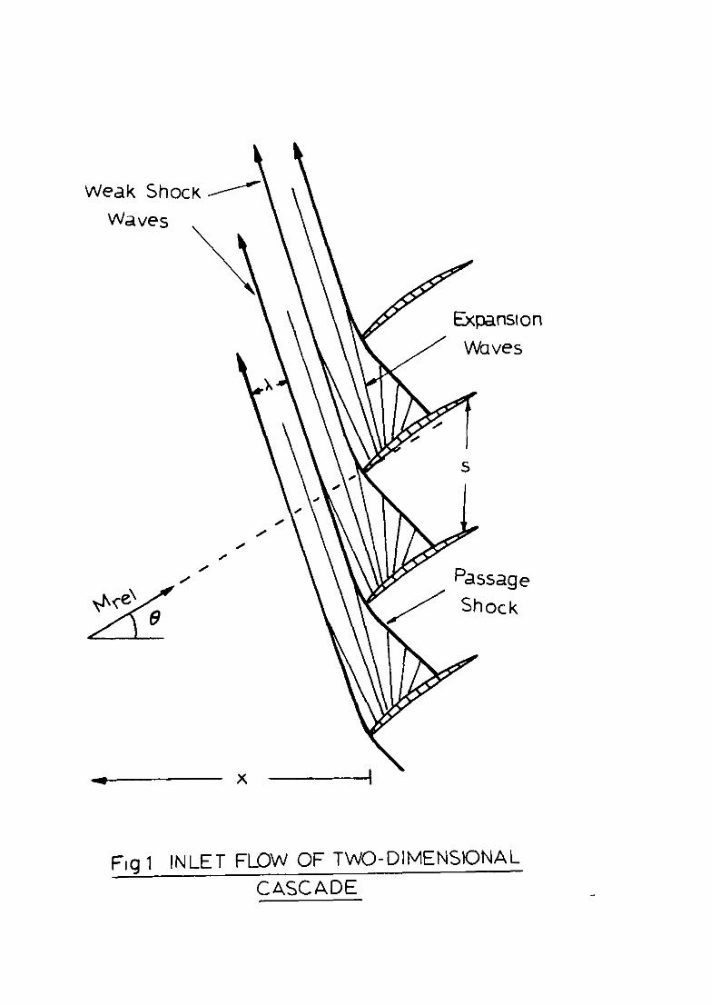
The 'aerodynamic' theories (Refs.3,4,5,6,7) replace the rotor by a two-dimenslonsl cascade representing a typical supersonic section of the blad1ng. The forward flow field for a set of identical blades with curved suction surfaces 1s depicted 1n kg.1. It consists of alternate shock wave6 attached at the leading edge and expansion waves emanating from the suction surface. Simple aerodynamic argument6 show that all flow variables - such a6 pressure, velocity - are constant along the expansion rays. The Mach number and flow angle 1n each expansion wave famaly are related by the Prandtl-Meyer function. The shock waves separate adlacent fam111es of waves and are determined by the property that they bisect, the angle of the two expan61on wave6 lntersectlng at that point. These condition6 are sufficient to determine the whole of the inlet flow field.
For a perfectly eymmetr1cal cascade, it 16 found that sufficiently far upstream (x >> rad2u6 of curvature of suction surface) the shocks are separated c1rcumferent1sll.y by the blade pitch 6, the pressure fall6 linearly between the shocks, and the shock strength Ap/p, 1s given by
Ap sZyfi - = - (JM"-1 cod - sin6)a. . . . . (1) PO x0,+1) Ma
Here M 1s the free stream relative Mach number and 6 the mean stagger angle of the blades. Nearer the cascade, the flow field 16 more complex, and decays
with distance like -3 x . It should be noted that the far field result (1) doss not depend upon either the mcldence or curvature of the blades but odY upon the free stream conditions. The prec16e blad1ng of the cascade doe6 not influence the far field pattern.

-4-
The flow field of an Imperfect cascade can be rnferred from the above model. The inclination of the expansion waves on each blade can still be related to the surface direction via the Prendtl-Meyer function, and the values of pressure, etc., on each ray deduced. However, they now vary from blade to blade. Likewise the shock waves are still located by the 'angle property' mentioned above, but again vary from blade to blade. In principle the whole flow faeld can then be calculated, although certaan compllcatlons arr8e where two shock waves merge. In practice it is necessary to resort to numerical techniques to calculate the upstream pressure profile for cascades with more than a few non-unaforrmties.
By means of a series of examples, a picture can be built up of the behaviour of irregular caScadea, and this picture confirms the prevrous ideas. The stronger shocks overtake the weaker ones, and the regularity of the shock pattern degenerates 86 it moves away from the cascade, transferring spectral energy from the BPF harmonic8 to the other rotatron order tones. It also shows the important point that during this transition phase, the decay of the overall level of the srgnal 18 slower than if the cascade bad no imperfections (Ref.6).
A varx+nt of this approach has been proposed in Ref.5, where a statiaticel analysis ha8 been attached to the model. The 'expected' acoustic field 1s then related to a statistical descrrption of the cascade irregularities (I.e., their means and variances) rather than their detailed values. ThlS has the obvious advantage of eliminating the need for a precise description of the
L cascade, but the converSe disadvantage that a particular measured ecoustrc field may be quite different from the predicted one , since it 1.5 only * single realisation of the field, and not the 'expected' one.
The 'non-linear acoustic' theory (%fs.7,8), on the other hand, regards the flow as unsteady one-dimensional, rather than steady two-dimensional. It ae8ume8 a~ known an initial pressure profile Just ahead of the cascade and analyse8 its subsequent progress along the duct. Thus this theory cannot take
accountofthe geometric detail.6 of the blades, nor predict the x+ near field decay, but it gives more insight Into the ultimate shock propagation process. The analysis proceeds in two stages. Firat, the development in time of the given initial profile is calculated. Second, the axial distance x covered by the shocks in thrs time is then deduced, bearing in mind that they spiral obliquely into the incoming flow. This allows an effective separation of the decay process - due to non-linearity and dissipataon - from the propagation process - due to compresslbilaty and convection by the aural inflow.
For a uniform cascade, thas approach lead8 to the following result. The shock strength at large time t is related solely to the time and the initial spacing X, end is independent of the initial amplitude;
AP 5 x - = -. . . . .
PO (Y + 1) sot (2)
For a flow at relative Nach number M end angle 9, the non-dimensional time sot/?. 1s related to X/S by
aOt x Ma
- = - x SC c
h?7 co& - sine -‘. 3
. . . . (3)
Clearly,/
-5-
Clearly, combining (2) and (3) gives exactly the same answer as before (1). For an irregular cascade, an initially asymmetric profile is assumed and its subsequent development computed numerically. The relationship between t and x can still be taken as (3). since this accounts for the propagation of the shocks at a mean speed ao; the effects of excess velocity are automatically accounted for in stage one. Again, computed results based on this approach confirm the tendency of the shock pattern to degenerate and transfer its spectral energy to the rotation frequency harmonics (Ref.8).
A third possible method of analysis would be to use the Whithan weak shock theory (Ref.q), which systematically improves a linear theory by taking account of the cumulative non-linear effects. This theory is used in sonic boom computations. This method also gives the result (I), but has certain extra advantages, see 5 4.
It should be mentioned in passing that a 'special case' exists in the aerodynamic theories. If the blade suction surfaces are all flat and parallel, then it can be shown that the incoming gas must also flow in this direction, and there are no shock or expansion waves present. The upstream gas is entirely undisturbed by the blades. At first sight, this would appear to be an ideal solution, as there is clearly no forward noise. Rowever. if it is admitted that all cascades have some slight imperfections, then a pattern of shock and expansion waves returns to the system , and these are of similar magnitude to those normally found on curved blades. Thus although nominally flat blades may make some differences to the multiple tone generation, they will not completely eliminate it; they are an ideel solution, not a practical one!
Thus, to summarise, all the present theories are effectively the same, and confirm and quantify our physical understanding of the problem. Clearly some implications can be drawn from these theories regarding the possibility of low noise transonx fens, but this is postponed to Y 5. In the next section, we discuss some of the deficaencies of these theories, in the hope that this may provoke some ideas on possible improvements.
4. Theoretical Deficiencies
The above theories are attractive both for their analytical and conceptual simplicity, end for their apparent agreement with experimental experience. Admittedly, a certain amount of 'adJustment' is required to correlate theory and experiment (e.g., careful selection of the right M and 8 to insert in (I)), but none the less these theories are often regarded as adequate. However, because they are two-dimensional (2D), they should strictly only apply in narrow annular ducts of constant cross-sectional area. Their application to real fans - where there is significant spanwise variation in conditions, as well as duct area changes - is clearly suspect, and merits a more critlcd appraisal.
There are two key predictions of the 2D theory, namely the
approximately x-l decay of the signal level, and the degeneration of the waveform with increasing axial distance. Taking the latter point first, although this is an undoubted prediction of the 2D theory, to my knowledge it does not tally accurately with real experimental results. For example in Ref,lO, a test compressor was inspected and its non-uniformities measured. These were used in a computer run to predict the forward pressure signature and spectral content. However, the agreement between the predicted and measured spectra was poor; the theory over-predicted the importance of the first few
shaft/
-6-
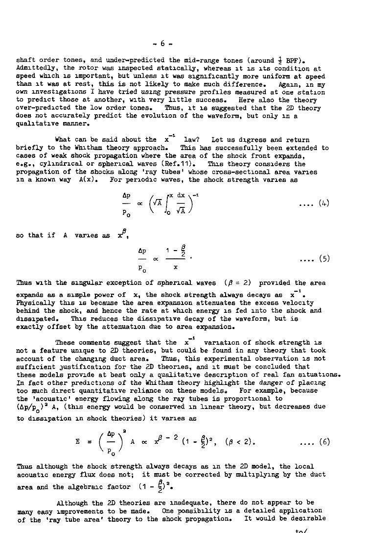
shaft order tones, and under-predicted the mid-range tones (around 3 BpF). Admittedly, the rOtOr was Inspected statically, whereas it is Its condition at speed which is important, but unless it was significantly more uniform at speed than It was at rest, this is not likely to make much difference. Agam, in my own investigations I have tried using pressure profiles measured at one station to predict those at another, with very little success. Here also the theory over-predicted the low order tones. Thus, It is suggested that the 2D theory does not accurately predict the evolutzon of the waveform, but only In a qualitative manner.
What can be said about the x-' law? Let us digress and return briefly to the Whitham theory approach. This has successfully been extended to cases of weak shock propagation where the area of the shock front expands, e.g., cylindrical or spherlcal waves (Ref.11). Thm theory considers the propagation of the shocks along 'ray tubes' whose cross-sectional area varies m a known way A(x). For periodic waves, the shock strength varies as
; oc (q;yl 0
so that if A varies ss $9
AP 1 -g -m -. . . . . (5) PO X
Thus with the singular exception of spherical waves (/Y = 2) provided the area
expands as a simple power of x, the shock strength always decays as x". physically this is because the area expansion attenuates the excess velocity behind the shock, and hence the rate at which energy 1s fed into the shock and dissipated. This reduces the dissipative decay of the waveform, but is exactly offset by the attenuation due to area expansion.
a These comments suggest that the x variation of shock strength 1s
not a feature unique to 2D theories, but could be found in any theory that took account of the changing duct area. Thus, this experimental observation 1s not sufficient Justification for the 2D theories, and It must be concluded that these models provide at best only a qualitative description of real fan situations. In fact other predictions of the Whitham theory highlight the danger of placing too much direct quantitative reliance on these models. For example, because the 'acoustic' energy flowing along the ray tubes is proportional to (Ap/p,)' A, (this energy would be conserved in linear theory, but decreases due to dissipation in shock theories) it varies as
$ - * (I - $)2, (a < 2).
Thus although the shock strength always decays as in the 2D model, the acoustic energy flux does not; it must be corrected by multiplying by
area and the algebraic factor (I - $1".
. . . . (6)
local the duct
Although the 2D theories are Inadequate, there do not appear to be many easy improvements to be made. One possibility is a detalled application of the 'ray tube area' theory to the shock propagation. It would be desirable
to/

-7-
to Sk0 incorporate the effects of the varying main stream axial velocity, a feature which was ignored in the previous discussion but which might well be slgnlflcant. This model would be a modest improvement on the 2D theories, as it would now apply to naf~ow annular ducts but of varying cross-sectional area, and it does appear to be a feasible problem. Although it would expose the precise effects of area change, lt is unlikely that any maJor new features will come to light. It would however, improve the prediction of the waveform degradation process, since increasing area slows down the non-linear effects of excess velocity, and 60 will inhibit the rapid build up of the low order tones.
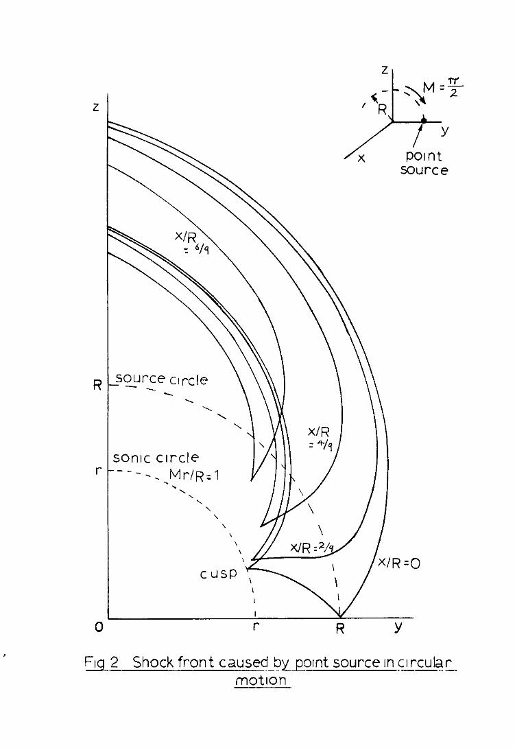
Beyond this, one has to face the fact that the real flow is truly three-dimensional, with significant radial variation in conditions, end that many more physical effects mu6t be considered. 'Ihe relative blade speed varie6 with radius, and passes through a 6onic condition at some intermediate point. (A6 the blade mtetes, this point sweeps out the 'sonic circle', and the cylinder formed on this circle by generators pamllel to the axis is termed the 'sonic cylinder'.) !Fhe blade aerodynamic flow near the 8onlc point is likely to exhibit all the complexities of transonic airfoil flow, and obtaining even a partial understanding of this region msy well be difficult. presumably there are no shock waves generated inside the sonic circle, but the tran6ition to a shocked flow outside the circle is likely to depend critically upon local conditions such es leading edge bluntness, boundary layers, etc. Consequently this region may well be a further cause of non-unifomuties in the inrtial shock pattern which will be exaggerated during propagation. If this 16 so, some means of stabilising this sonic transition mey be desirable.
The 6onic cylinder al.60 plays a role in the forward propagation of the ShOCks. It is well known that the shock fmnt generated in free space by an accelerating body contains a cusp. For a body mtating in a circle the shock fmnt never penetrate6 inside the sonic cylinder, instead the inward arm is cusped and then pmpagates outwards. Fig.2 shows a typical example, it is a contour plot of the shock front generated by a point disturbance mtating at Mach number N = ?r/2. A similar feature still applies to a ducted rotor, although the outer w&i now reflects the shocks inward again and alters the picture from Fig.2. However, it still remains true that no shocks enter the sonic cylinder, so what happens if the forward ducting is narmwed to a diameter less than that of the cylinder? Do the shocks get trapped and fail to propagate out of the duct'?
The final, and perhaps most important feature of the shock propagation process 16 the fact that acoustic wave6 inside a duct are dispersive. Due to the constraint imposed by the wall, only certain duct modes can exist, and these all propagate at different speeds. Hence any initial wave shape is distorted, and this combined with the fact that the flow is non-linear means that the shock propagation is essentially a problem in a non-linear dispersive system., Although 6ome recent investigation6 have been made in this area they are specifically restricted to unshocked modes. However, they do show an important new effect termed 'subsonic choking I (Ref.12) in which a mtating mode is prevented fmm propagating forward by an axial velocity less than sonic due to the combination of non-linear and dispersive effects. Maybe there 16 a similar effect on shocked modes.
chum to conclude, it appears that the 2D theoriee areseverelylimited in their relevance to reel transonic fans, in that IWny important Physical effects are not incorporated. Unfortunately, the desirable theoretical improvements will be difficult, involving concepts from both transonic flows and non-linear dispersion theory, end so mey not yield to theoretical attack for a long time.
-a-
5. Conclusions
!Che physical and mathematical models described in & 2 & 3 obviously have various implications regarding the possibility of designing quiet transonic fans. These will now be described in more detail.
(I) Multiple tone noise is an inevitable consequence of the steady aerodynamic flow around the blades, and results from the special behaviour of the blade shock waves. Its detailed form depends greatly upon the pattern of dissimilarities between the blades, but does not depend strongly on the normnal blade design. Consequently it is neither accurately predictable nor repeatable from one fan to another, nor is it likely to be seriously altered by changes in fan bladmng.
(2) The propagation of the shock waves is a process of simultaneous decay and degradation of the original ordered waveform into a smaller, disordered one. Thus It ~6 not possible to have low overall levels without widespread distributions of tones.
(3) If low overall level is the primary aim, then the design obJectl.ve is simply to maximise the non-dimensional time sot/h spent by the shocks in the duct. This can be achieved by either reducing the blade spacing (increasing the number of blades) or increasing the duct length. Alternatively, the velocity triangles can be chosen to increase the factor in T&n.(3) (see Fig.7 or Ref.8); in general an axial velocity as high as possible is required, as this makes it harder for the shocks to propagate forward. ThlS mplles an increase Ln relative Mach number or stagger angle, but requires mayor aerodynamic changes to the rotor and may be impossible due to other aerodynamic constraints.
(4) !Che effects of increasing the duct area can be described qualitatively, and are unhelpful for achieving low overall levels. This is because in expanding ducts, the rate of destruction of acoustic energy is reduced. Also the axial velocity will decrease and so allow the shocks to travel down the duct more quickly.
The above points appear to cover most of thelow noise implications in our present understanding. Certainly, much more detail could be extracted from the 2D theories, but in view of the comments in 6 4, these are likely to be of limited application to reel fans. These implications lead to a rather pessimistic view of the possibility of quiet high speed fans. A 20 dB reduction in overall level at the duct exit would require at least a tenfold increase In a,& and although this is not completely impossible It does appear to be at the limit of what could be reached using present aerodynamic technology.
There then remains the possibility that the present theories mxss some vital physical mechanism which could be turned to advantage, such as those mentioned in d 4. It is clear that the present theories are far from exhaustive, and it is quite probable that some new features will be revealed theoretically in due course. Rowever, there appears to be an urgent need for some experimental work on this problem, in particular looking at the strengths, locations, and behaviour of the shock waves in the duct near the rotor and
especially/

-9-
especx+lly their three-dimensional features. !l'hls could be done both on current fan confrgurations and elso on some of the more radxal possibilities that might be suggested. Such experlmentel work would both stimulate the theory, and perhaps expose some of these other mechanisms that hopefully ~11 ultimately allow the operation of quiet transonic rotors.
Acknowledgement
'l!h~s report V&B prepared whist the author wae supported by an SIEC research grant.
References/

- IO -
References , ,,
RtLe, etc. ' No. Author(s) -
1 Tyler and Sofr1n
2 Sofrln and Pxkett
3 YmagudU
4 KUrOSaka
5 Pxkett
6 Fink
7 Morfey and Fisher
a Hawkzngs
9 whltham
10 Kantola and Kurosaka
Axial flow compressor noise studies. SAE Trans. z, pp.309-332. 1962. 2
Multiple pure tone noze generated by fans at supersonxc tip speeds. International symposium on fluid mechanxs and design of turbomachinery. Penn. State Unlverslty. 1970.
On the Inlet flow field for a two-dlmenslonal cascade wxth curved entrance region. Sulletln of JSME 2, 25, pp.91-95. 1964.
A note on multiple pure tone noise. JSV 2, 4, pp.453~462. 1971.
The predxtion of the spectral content of combination tone noxe. AIAA Paper No. 71-730. 1971.
Shock wave behaviour III transonzc compressor noxe generatlon. ASHE Paper No. 7'l-GT-7. 1971.
Shock wave radiation from a supersonx ducted rotor. Aeronaut. J. 2, pp.579-5a5. 1970.
Multiple tone generatlon by transonic compressors. JSV-'& 2, pp.241-250. 1971.
The flow pattern of a supersonx projectile. Corn. Pure & App. Maths. 5, pp.301-348. 1952.
The theoretIcal and experimental lnvestlgatlons on multiple pure tone noise - Part 1. NASA CR-1831.
II/
NO. - Author(s) ht.le, etc.
11 whlthm On the propegatlon of week shock waves. JFMI; 3. pp.w-318. 1956.
12 TWJ
- 11 -
On funte amplitude spurring acoustic modes and subsonic choking. JSV 16, 3, pp.393~405. 1971.
PAC

Weak ShocK A
Waves
\V Expansion
/ Waves
Flq 1 INLET FLOW OF TWO-DIMENSIONAL CASCADE

_so_urce ctrcle \ \\ I
source
jOnlC circle --- -.,~r/R=l
\
‘R-O
Fq 2 Shock front caused by pornt source In circular -- motion

- - - I-__ - - - -_ - . - .__ - - __._- . . - - . . _ - - - - - - - - - - . - _-_/ -_. ._ - ___.__,___
I,__,_.,__,__ . , _ . . - , _ . - _._____ - . . - - . _. - - - - . -
e :: G ARC CP No.1226 ; Harch, 1972
Sawkings, D.
!F&ULSONIC FAN NOISE
Multiple pure tone generation by transonx fans is discussed. Thm 1s explained in terms of weak shock theory, and the various related mathematical models are outlined. The implications of these models for the design of quieter transonic fans are emphasised. Some important physical features not yet included in these theories are also highlighted.
ARC CP ~0.1226 March, 1972
Sawkings, D.
IRANSONIC FAN NOISE
Multiple pure tone generation by transonx fans is discussed. This 1s explained in terms of weak shock theory, and the various related mathematical models are outlined. The implications of these models for the design of quieter transonic fans are emphasised. Some important physical features not yet included in these theories are also highlighted.
AFC CP ~0.1226 March, 1972
~ Sawkings, D.
TMNSONIC FAN NOISE
Multiple pure tone generation by transonx fans LY discussed. This is explained in terms of weak shock theory, and the various related mathematical models are outlined. The implications of these models for the design of quieter transonic fans are emphasised. some important physical features not yet included in these theories are also highlighted.


C.P. No. 1226
HER MAJESTY’S STATIONERY OFFICE
49 H@ Holborn, London WClV 6HB 13a Castle Street, Edmburgb EHZ 3AR
109 St Mary Sueet, Carddf CF, IJW Brazennose Street, Manchester M60 SAS
50 Farfax Street, Bristol BSl 3DE 258 Broad Street, B,rm,,,gh.m, B, ZHE 80 Clucherter Street, Belfast BT1 4JY
C.P. No. 1226 bEPI Il47Ois47