transparent conductive oxide-free perovskite solar · pdf filetransparent conductive...
TRANSCRIPT
Transparent Conductive Oxide-Free Perovskite Solar Cells withPEDOT:PSS as Transparent ElectrodeKuan Sun,†,‡ Pengcheng Li,† Yijie Xia,† Jingjing Chang,† and Jianyong Ouyang*,†
†Department of Materials Science & Engineering, National University of Singapore, 7 Engineering Drive 1, Singapore 117574‡School of Power Engineering, Chongqing University, 174 Shazhengjie, Shapingba, Chongqing 400044, China
*S Supporting Information
ABSTRACT: Perovskite solar cells (PSCs) have been attracting considerable attentionbecause of their low fabrication cost and impressive energy conversion efficiency. MostPSCs are built on transparent conductive oxides (TCOs) such as fluorine-doped tin oxide(FTO) or indium tin oxide (ITO), which are costly and rigid. Therefore, it is significantto explore alternative materials as the transparent electrode of PSCs. In this study, highlyconductive and highly transparent poly(3,4-ethylenedioxythiophene):polystyrene-sulfonate (PEDOT:PSS) films were investigated as the transparent electrode of bothrigid and flexible PSCs. The conductivity of PEDOT:PSS films on rigid glass or flexiblepoly(ethylene terephthalate) (PET) substrate is significantly enhanced through atreatment with methanesulfonic acid (MSA). The optimal power conversion efficiency(PCE) is close to 11% for the rigid PSCs with an MSA-treated PEDOT:PSS film as thetransparent electrode on glass, and it is more than 8% for the flexible PSCs with a MSA-treated PEDOT:PSS film as the transparent electrode on PET. The flexible PSCs exhibitexcellent mechanical flexibility in the bending test.
KEYWORDS: perovskite solar cell, PEDOT:PSS, transparent electrode, flexible solar cell, interface engineering
1. INTRODUCTION
Perovskite solar cells have been attracting considerableattention because of their low fabrication cost and impressiveenergy conversion efficiency. They can be fabricated bysolution processing.1 The planar perovskite solar cells do nothave a scaffold oxide layer. They could thus be manufactured bya roll-to-roll (R2R) coating process.2 The high ambipolarcharge mobility in perovskite films enables optimal active layerthickness of a few hundreds of nanometers,3−7 making printingof working PSCs more reproducible.8 Meanwhile, a flat andflexible transparent electrode is highly desirable to becompatible with the R2R process. Most PSCs are built ontransparent conductive oxides (TCOs) such as fluorine-dopedtin oxide (FTO) or indium tin oxide (ITO),9−19 which cancause the degradation of PSCs after bending because theseTCOs are brittle materials.20,21 Moreover, the transparentconductive electrode is the most expensive component inperovskite solar cells. Its cost is about 10 times of that of theperovskite layer in a PSC. Therefore, it is significant to explorealternative materials as the transparent electrode of PSCs.Recently, silver or gold thin films or silver nanowires have beenused as a transparent electrode for perovskite solar cells.18,22−24
However, iodide is quite corrosive for Ag or other metalnanostructures. To prepare metal nanowires and assemblethem for transparent electrode is also costly.In this study, we investigated the application of methane-
sulfonic acid (MSA)-treated poly(3,4-ethylenedioxythio-phene):polystyrenesulfonate (PEDOT:PSS) as the transparentelectrode of organo-lead halide perovskite solar cells. The
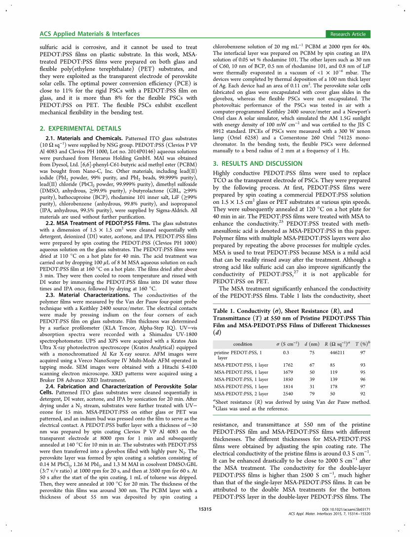
chemical structures of MSA and PEDOT:PSS are shown inChart 1. PEDOT:PSS is the most successful conductingpolymer because of its solution processability, high trans-parency in the visible range, and excellent thermal stability. Ithas been reported that treatment of PEDOT:PSS films with anacid such as sulfuric acid and MSA can improve theconductivity to be comparable to that of ITO.25−27 However,
Received: April 13, 2015Accepted: July 1, 2015Published: July 1, 2015
Chart 1. Chemical Structure of PEDOT:PSS andMethanesulfonic Acid
Research Article
www.acsami.org
© 2015 American Chemical Society 15314 DOI: 10.1021/acsami.5b03171ACS Appl. Mater. Interfaces 2015, 7, 15314−15320
sulfuric acid is corrosive, and it cannot be used to treatPEDOT:PSS films on plastic substrate. In this work, MSA-treated PEDOT:PSS films were prepared on both glass andflexible poly(ethylene terephthalate) (PET) substrates, andthey were exploited as the transparent electrode of perovskitesolar cells. The optimal power conversion efficiency (PCE) isclose to 11% for the rigid PSCs with a PEDOT:PSS film onglass, and it is more than 8% for the flexible PSCs withPEDOT:PSS on PET. The flexible PSCs exhibit excellentmechanical flexibility in the bending test.
2. EXPERIMENTAL DETAILS2.1. Materials and Chemicals. Patterned ITO glass substrates
(10 Ω sq−1) were supplied by NSG group. PEDOT:PSS (Clevios P VPAl 4083 and Clevios PH 1000, Lot no. 2014P0146) aqueous solutionswere purchased from Heraeus Holding GmbH. MAI was obtainedfrom Dyesol, Ltd. [6,6]-phenyl-C61-butyric acid methyl ester (PCBM)was bought from Nano-C, Inc. Other materials, including lead(II)iodide (PbI2 powder, 99% purity, and PbI2 beads, 99.999% purity),lead(II) chloride (PbCl2 powder, 99.999% purity), dimethyl sulfoxide(DMSO, anhydrous, ≥99.9% purity), γ-butyrolactone (GBL, ≥99%purity), bathocuproine (BCP), rhodamine 101 inner salt, LiF (≥99%purity), chlorobenzene (anhydrous, 99.8% purity), and isopropanol(IPA, anhydrous, 99.5% purity), were supplied by Sigma-Aldrich. Allmaterials are used without further purification.2.2. MSA Treatment of PEDOT:PSS Films. The glass substrates
with a dimension of 1.5 × 1.5 cm2 were cleaned sequentially withdetergent, deionized (DI) water, acetone, and IPA. PEDOT:PSS filmswere prepared by spin coating the PEDOT:PSS (Clevios PH 1000)aqueous solution on the glass substrates. The PEDOT:PSS films weredried at 110 °C on a hot plate for 40 min. The acid treatment wascarried out by dropping 100 μL of 8 M MSA aqueous solution on eachPEDOT:PSS film at 160 °C on a hot plate. The films dried after about3 min. They were then cooled to room temperature and rinsed withDI water by immersing the PEDOT:PSS films into DI water threetimes and IPA once, followed by drying at 160 °C.2.3. Material Characterizations. The conductivities of the
polymer films were measured by the Van der Pauw four-point probetechnique with a Keithley 2400 source/meter. The electrical contactswere made by pressing indium on the four corners of eachPEDOT:PSS film on glass substrate. Film thickness was determinedby a surface profilometer (KLA Tencor, Alpha-Step IQ). UV−visabsorption spectra were recorded with a Shimadzu UV-1800spectrophotometer. UPS and XPS were acquired with a Kratos AxisUltra X-ray photoelectron spectroscope (Kratos Analytical) equippedwith a monochromatized Al Kα X-ray source. AFM images wereacquired using a Veeco NanoScope IV Multi-Mode AFM operated intapping mode. SEM images were obtained with a Hitachi S-4100scanning electron microscope. XRD patterns were acquired using aBruker D8 Advance XRD Instrument.2.4. Fabrication and Characterization of Perovskite Solar
Cells. Patterned ITO glass substrates were cleaned sequentially indetergent, DI water, acetone, and IPA by sonication for 20 min. Afterdrying under a N2 stream, substrates were further treated with UV−ozone for 15 min. MSA-PEDOT:PSS on either glass or PET waspatterned, and an indium bud was pressed onto the film to serve as theelectrical contact. A PEDOT:PSS buffer layer with a thickness of ∼30nm was prepared by spin coating Clevios P VP Al 4083 on thetransparent electrode at 8000 rpm for 1 min and subsequentlyannealed at 140 °C for 10 min in air. The substrates with PEDOT:PSSwere then transferred into a glovebox filled with highly pure N2. Theperovskite layer was formed by spin coating a solution consisting of0.14 M PbCl2, 1.26 M PbI2, and 1.3 M MAI in cosolvent DMSO:GBL(3:7 v/v ratio) at 1000 rpm for 20 s, and then at 3500 rpm for 60 s. At50 s after the start of the spin coating, 1 mL of toluene was dripped.Then, they were annealed at 100 °C for 20 min. The thickness of theperovskite thin films was around 300 nm. The PCBM layer with athickness of about 55 nm was deposited by spin coating a
chlorobenzene solution of 20 mg mL−1 PCBM at 2000 rpm for 40s.The interfacial layer was prepared on PCBM by spin coating an IPAsolution of 0.05 wt % rhodamine 101. The other layers such as 30 nmof C60, 10 nm of BCP, 0.5 nm of rhodamine 101, and 0.8 nm of LiFwere thermally evaporated in a vacuum of <1 × 10⁻⁶ mbar. Thedevices were completed by thermal deposition of a 100 nm thick layerof Ag. Each device had an area of 0.11 cm2. The perovskite solar cellsfabricated on glass were encapsulated with cover glass slides in theglovebox, whereas the flexible PSCs were not encapsulated. Thephotovoltaic performance of the PSCs was tested in air with acomputer-programmed Keithley 2400 source/meter and a Newport’sOriel class A solar simulator, which simulated the AM 1.5G sunlightwith energy density of 100 mW cm−2 and was certified to the JIS C8912 standard. IPCEs of PSCs were measured with a 300 W xenonlamp (Oriel 6258) and a Cornerstone 260 Oriel 74125 mono-chromator. In the bending tests, the flexible PSCs were deformedmanually to a bend radius of 2 mm at a frequency of 1 Hz.
3. RESULTS AND DISCUSSIONHighly conductive PEDOT:PSS films were used to replaceTCO as the transparent electrode of PSCs. They were preparedby the following process. At first, PEDOT:PSS films wereprepared by spin coating a commercial PEDOT:PSS solutionon 1.5 × 1.5 cm2 glass or PET substrates at various spin speeds.They were subsequently annealed at 120 °C on a hot plate for40 min in air. The PEDOT:PSS films were treated with MSA toenhance the conductivity.25 PEDOT:PSS treated with meth-anesulfonic acid is denoted as MSA-PEDOT:PSS in this paper.Polymer films with multiple MSA-PEDOT:PSS layers were alsoprepared by repeating the above processes for multiple cycles.MSA is used to treat PEDOT:PSS because MSA is a mild acidthat can be readily rinsed away after the treatment. Although astrong acid like sulfuric acid can also improve significantly theconductivity of PEDOT:PSS,27 it is not applicable forPEDOT:PSS on PET.The MSA treatment significantly enhanced the conductivity
of the PEDOT:PSS films. Table 1 lists the conductivity, sheet
resistance, and transmittance at 550 nm of the pristinePEDOT:PSS film and MSA-PEDOT:PSS films with differentthicknesses. The different thicknesses for MSA-PEDOT:PSSfilms were obtained by adjusting the spin coating rate. Theelectrical conductivity of the pristine films is around 0.3 S cm−1.It can be enhanced drastically to be close to 2000 S cm−1 afterthe MSA treatment. The conductivity for the double-layerPEDOT:PSS films is higher than 2500 S cm−1, much higherthan that of the single-layer MSA-PEDOT:PSS films. It can beattributed to the double MSA treatments for the bottomPEDOT:PSS layer in the double-layer PEDOT:PSS films. The
Table 1. Conductivity (σ), Sheet Resistance (R), andTransmittance (T) at 550 nm of Pristine PEDOT:PSS ThinFilm and MSA-PEDOT:PSS Films of Different Thicknesses(d)
condition σ (S cm−1) d (nm) R (Ω sq−1)a T (%)b
pristine PEDOT:PSS, 1layer
0.3 75 446211 97
MSA-PEDOT:PSS, 1 layer 1762 67 85 93MSA-PEDOT:PSS, 1 layer 1679 50 119 95MSA-PEDOT:PSS, 1 layer 1850 39 139 96MSA-PEDOT:PSS, 1 layer 1814 31 178 97MSA-PEDOT:PSS, 2 layer 2540 79 50 92aSheet resistance (R) was derived by using Van der Pauw method.bGlass was used as the reference.
ACS Applied Materials & Interfaces Research Article
DOI: 10.1021/acsami.5b03171ACS Appl. Mater. Interfaces 2015, 7, 15314−15320
15315
conductivity enhancement can be ascribed to the MSA-inducedphase segregation between PSS and PEDOT in thePEDOT:PSS film and coil-to-linear conformational change ofthe PEDOT chains.25−30
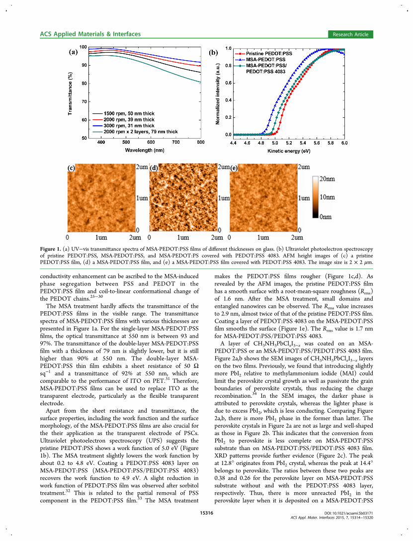
The MSA treatment hardly affects the transmittance of thePEDOT:PSS films in the visible range. The transmittancespectra of MSA-PEDOT:PSS films with various thicknesses arepresented in Figure 1a. For the single-layer MSA-PEDOT:PSSfilms, the optical transmittance at 550 nm is between 93 and97%. The transmittance of the double-layer MSA-PEDOT:PSSfilm with a thickness of 79 nm is slightly lower, but it is stillhigher than 90% at 550 nm. The double-layer MSA-PEDOT:PSS thin film exhibits a sheet resistance of 50 Ωsq−1 and a transmittance of 92% at 550 nm, which arecomparable to the performance of ITO on PET.31 Therefore,MSA-PEDOT:PSS films can be used to replace ITO as thetransparent electrode, particularly as the flexible transparentelectrode.Apart from the sheet resistance and transmittance, the
surface properties, including the work function and the surfacemorphology, of the MSA-PEDOT:PSS films are also crucial forthe their application as the transparent electrode of PSCs.Ultraviolet photoelectron spectroscopy (UPS) suggests thepristine PEDOT:PSS shows a work function of 5.0 eV (Figure1b). The MSA treatment slightly lowers the work function byabout 0.2 to 4.8 eV. Coating a PEDOT:PSS 4083 layer onMSA-PEDOT:PSS (MSA-PEDOT:PSS/PEDOT:PSS 4083)recovers the work function to 4.9 eV. A slight reduction inwork function of PEDOT:PSS film was observed after sorbitoltreatment.32 This is related to the partial removal of PSScomponent in the PEDOT:PSS film.33 The MSA treatment
makes the PEDOT:PSS films rougher (Figure 1c,d). Asrevealed by the AFM images, the pristine PEDOT:PSS filmhas a smooth surface with a root-mean-square roughness (Rrms)of 1.6 nm. After the MSA treatment, small domains andentangled nanowires can be observed. The Rrms value increasesto 2.9 nm, almost twice of that of the pristine PEDOT:PSS film.Coating a layer of PEDOT:PSS 4083 on the MSA-PEDOT:PSSfilm smooths the surface (Figure 1e). The Rrms value is 1.7 nmfor MSA-PEDOT:PSS/PEDOT:PSS 4083.A layer of CH3NH3PbClxI3−x was coated on an MSA-
PEDOT:PSS or an MSA-PEDOT:PSS/PEDOT:PSS 4083 film.Figure 2a,b shows the SEM images of CH3NH3PbClxI3−x layerson the two films. Previously, we found that introducing slightlymore PbI2 relative to methylammonium iodide (MAI) couldlimit the perovskite crystal growth as well as passivate the grainboundaries of perovskite crystals, thus reducing the chargerecombination.34 In the SEM images, the darker phase isattributed to perovskite crystals, whereas the lighter phase isdue to excess PbI2, which is less conducting. Comparing Figure2a,b, there is more PbI2 phase in the former than latter. Theperovskite crystals in Figure 2a are not as large and well-shapedas those in Figure 2b. This indicates that the conversion fromPbI2 to perovskite is less complete on MSA-PEDOT:PSSsubstrate than on MSA-PEDOT:PSS/PEDOT:PSS 4083 film.XRD patterns provide further evidence (Figure 2c). The peakat 12.8° originates from PbI2 crystal, whereas the peak at 14.4°belongs to perovskite. The ratios between these two peaks are0.38 and 0.26 for the perovskite layer on MSA-PEDOT:PSSsubstrate without and with the PEDOT:PSS 4083 layer,respectively. Thus, there is more unreacted PbI2 in theperovskite layer when it is deposited on a MSA-PEDOT:PSS
Figure 1. (a) UV−vis transmittance spectra of MSA-PEDOT:PSS films of different thicknesses on glass. (b) Ultraviolet photoelectron spectroscopyof pristine PEDOT:PSS, MSA-PEDOT:PSS, and MSA-PEDOT:PS covered with PEDOT:PSS 4083. AFM height images of (c) a pristinePEDOT:PSS film, (d) a MSA-PEDOT:PSS film, and (e) a MSA-PEDOT:PSS film covered with PEDOT:PSS 4083. The image size is 2 × 2 μm.
ACS Applied Materials & Interfaces Research Article
DOI: 10.1021/acsami.5b03171ACS Appl. Mater. Interfaces 2015, 7, 15314−15320
15316
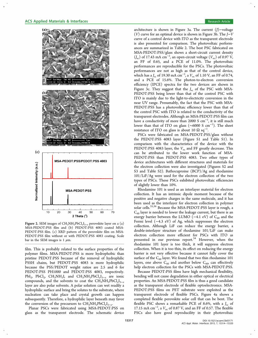
film. This is probably related to the surface properties of thepolymer films. MSA-PEDOT:PSS is more hydrophobic thanpristine PEDOT:PSS because of the removal of hydrophilicPSSH chains, but PEDOT:PSS 4083 is more hydrophilicbecause the PSS/PEDOT weight ratios are 2.5 and 6 forPEDOT:PSS PH1000 and PEDOT:PSS 4083, respectively.PbI2, PbCl2, CH3NH3I, and CH3NH3PbClxI3−x are ioniccompounds, and the solvents to coat the CH3NH3PbClxI3−xlayer are also polar solvents. A polar solution can wet readily ahydrophilic surface and bring the solutes to the substrate, wherenucleation can take place and crystal growth can happensubsequently. Therefore, a hydrophilic layer beneath may favorthe conversion of the precursors to CH3NH3PbClxI3−x.Planar PSCs were fabricated using MSA-PEDOT:PSS on
glass as the transparent electrode. The schematic device
architecture is shown in Figure 3a. The current (J)−voltage(V) curve for an optimal device is shown in Figure 3b. The J−Vcurve of a control device with ITO as the transparent electrodeis also presented for comparison. The photovoltaic perform-ances are summarized in Table 2. The best PSC fabricated onMSA-PEDOT:PSS/glass shows a short-circuit current density(Jsc) of 17.43 mA cm−2, an open-circuit voltage (Voc) of 0.97 V,an FF of 0.65, and a PCE of 11.0%. The photovoltaicperformances are reproducible for the PSCs. The photovoltaicperformances are not as high as that of the control device,which has a Jsc of 19.30 mA cm−2, a Voc of 1.10 V, an FF of 0.74,and a PCE of 15.6%. The photon-to-electron conversionefficiency (IPCE) spectra for the two devices are shown inFigure 3c. They suggest that the Jsc of the PSC with MSA-PEDOT:PSS being lower than that of the control PSC withITO is mainly due to the light-to-electricity conversion in thenear UV range. Presumably, the fact that the PSC with MSA-PEDOT:PSS has a photovoltaic efficiency lower than that ofthe control PSC with ITO is related to the conductivity of thetransparent electrodes. Although an MSA-PEDOT:PSS film canhave a conductivity of more than 2000 S cm−1, it is still muchlower than that of ITO on glass (∼6000 S cm−1). The sheetresistance of ITO on glass is about 10 Ω sq−1.PSCs were fabricated on MSA-PEDOT:PSS/glass without
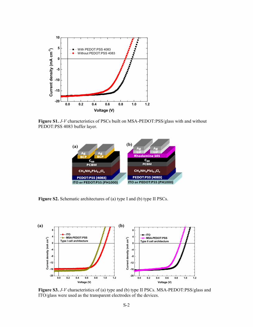
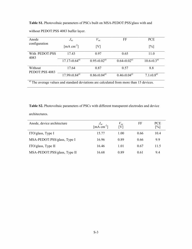
the PEDOT:PSS 4083 layer (Figure S1 and Table S1). Incomparison with the characteristics of the device with thePEDOT:PSS 4083 layer, the Voc and FF greatly decrease. Thiscan be attributed to the lower work function of MSA-PEDOT:PSS than PEDOT:PSS 4083. Two other types ofdevice architectures with different structures and materials forthe electron collection were also investigated (Figures S2 andS3 and Table S2). Bathocuproine (BCP)/Ag and rhodamine101/LiF/Ag were used for the electron collection of the twotypes of PSCs. These PSCs exhibited photovoltaic efficienciesof slightly lower than 10%.Rhodamine 101 is used as an interlayer material for electron
collection. It has an intrinsic dipole moment because of thepositive and negative charges in the same molecule, and it hasbeen used as the interlayer for electron collection in polymersolar cells.35,36 Because the MSA-PEDOT:PSS layer is rough, aC60 layer is needed to lower the leakage current, but there is anenergy barrier between the LUMO (−4.1 eV) of C60 and theFermi level (−4.3 eV) of Ag, which suppresses the electroncollection. Although LiF can reduce the energy barrier, adouble-interlayer structure of rhodamine 101/LiF can makeelectron collection more efficient for PSCs with ITO aspresented in our previous report.34 However, when therhodamine 101 layer is too thick, it will suppress electroncollection. When it is too thin, its effect on reducing the energybarrier is not very effective because it cannot fully cover thesurface of the C60 layer. We found that two thin rhodamine 101layers, one above C60 and another below C60, can effectivelyhelp electron collection for the PSCs with MSA-PEDOT:PSS.Because PEDOT:PSS films have high mechanical flexibility,
bending will not cause degradation in either optical or electricalproperties. An MSA-PEDOT:PSS film is thus a good candidateas the transparent electrode of flexible optoelectronics. MSA-PEDOT:PSS films on PET substrate were exploited as thetransparent electrode of flexible PSCs. Figure 4a shows acompleted flexible perovskite solar cell that can be bent. Theflexible PSC shows a remarkable PCE of 8.6%, with a Jsc of17.15 mA cm−2, a Voc of 0.87 V, and an FF of 0.57. The flexiblePSCs also have good reproducility in their photovoltaic
Figure 2. SEM images of CH3NH3PbClxI3−x perovskite layer on a (a)MSA-PEDOT:PSS film and (b) PEDOT:PSS 4083 coated MSA-PEDOT:PSS film. (c) XRD pattern of the perovskite film on MSA-PEDOT:PSS film without or with PEDOT:PSS 4083 coating. Scalebar in the SEM images is 1 μm.
ACS Applied Materials & Interfaces Research Article
DOI: 10.1021/acsami.5b03171ACS Appl. Mater. Interfaces 2015, 7, 15314−15320
15317
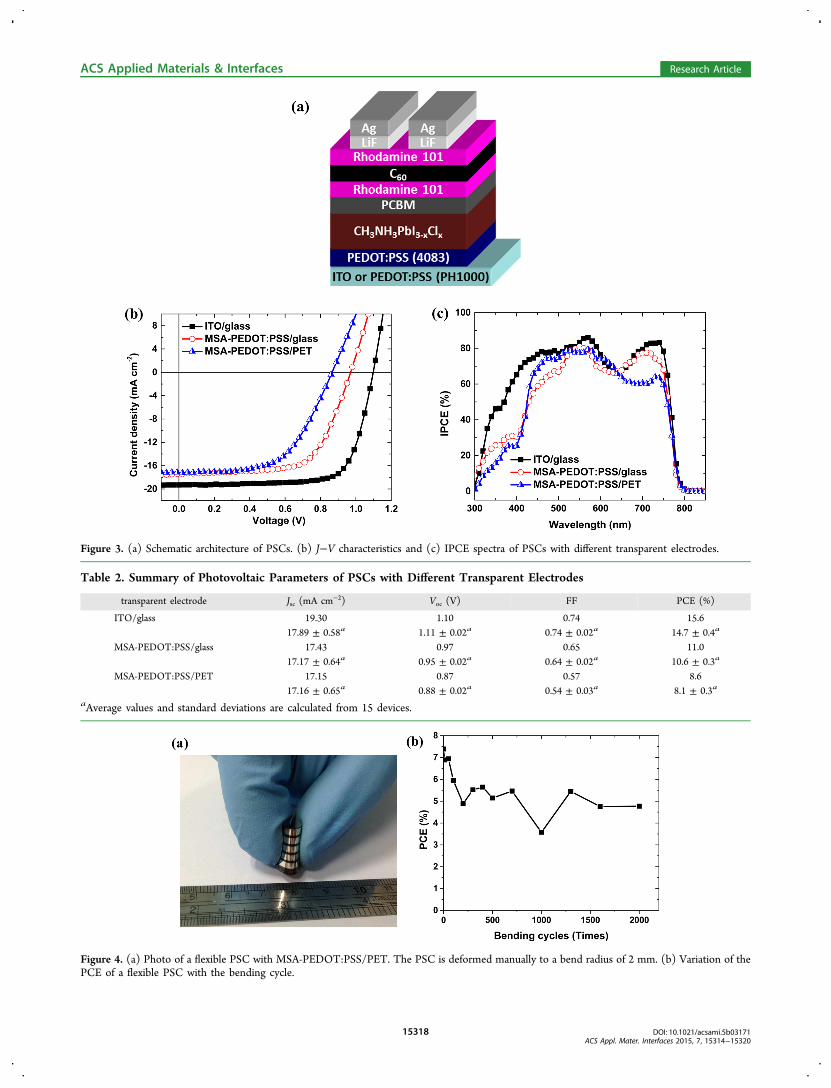
Figure 3. (a) Schematic architecture of PSCs. (b) J−V characteristics and (c) IPCE spectra of PSCs with different transparent electrodes.
Table 2. Summary of Photovoltaic Parameters of PSCs with Different Transparent Electrodes
transparent electrode Jsc (mA cm−2) Voc (V) FF PCE (%)
ITO/glass 19.30 1.10 0.74 15.617.89 ± 0.58a 1.11 ± 0.02a 0.74 ± 0.02a 14.7 ± 0.4a
MSA-PEDOT:PSS/glass 17.43 0.97 0.65 11.017.17 ± 0.64a 0.95 ± 0.02a 0.64 ± 0.02a 10.6 ± 0.3a
MSA-PEDOT:PSS/PET 17.15 0.87 0.57 8.617.16 ± 0.65a 0.88 ± 0.02a 0.54 ± 0.03a 8.1 ± 0.3a
aAverage values and standard deviations are calculated from 15 devices.
Figure 4. (a) Photo of a flexible PSC with MSA-PEDOT:PSS/PET. The PSC is deformed manually to a bend radius of 2 mm. (b) Variation of thePCE of a flexible PSC with the bending cycle.
ACS Applied Materials & Interfaces Research Article
DOI: 10.1021/acsami.5b03171ACS Appl. Mater. Interfaces 2015, 7, 15314−15320
15318
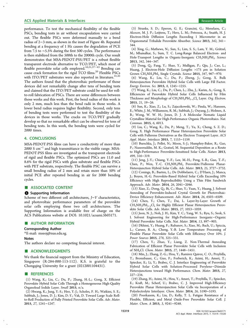
performance. To test the mechanical flexibility of the flexiblePSCs, bending tests in air without encapsulation were carriedout. The flexible PSCs were deformed manually to a bendradius of 2−3 mm, as shown in the inset of Figure 4b. Repeatedbending at a frequency of 1 Hz causes the degradation of PCEfrom 7.5 to ∼5.5% during the first 500 cycles. The performanceis then stabilized from the 500th to the 2000th cycle. Our resultdemonstrates that MSA-PEDOT:PSS/PET is a robust flexibletransparent electrode alternative to TCO/PET, which most offlexible perovskite solar cells employed.16,21,37−43 Bending cancause crack formation for the rigid TCO films.20 Flexible PSCswith ITO/PET substrates were also reported in literature.41,42
The authors found that the photovoltaic performane of thosedevices did not remarkably change after tens of bending testsand claimed that the ITO/PET substrate could be used for roll-to-roll fabrication of PSCs. There are some differences betweenthose works and this work. First, the bend radius of this work isonly 2 mm, much less than the bend radii in those works. Alower bend radius requires higher flexibility. Second, only tensof bending tests were performed to test the flexibility of thedevices in those works. The cracks on TCO/PET graduallydevelop so that no remarkable effect can be observed for tens ofbending tests. In this work, the bending tests were cycled for2000 times.
4. CONCLUSIONSMSA-PEDOT:PSS films can have a conductivity of more than2000 S cm−1 and high transmittance in the visible range. MSA-PEDOT:PSS films are investigated as the transparent electrodeof rigid and flexible PSCs. The optimized PSCs are 11.0 and8.6% for the rigid PSCs with glass substrate and flexible PSCswith PET substrate, respectively. The flexible PSC can survive asmall bending radius of 2 mm and retain more than 50% ofinitial PCE after repeated bending in air for 2000 bendingcycles.
■ ASSOCIATED CONTENT*S Supporting InformationScheme of two different cell architectures, J−V characteristics,and photovoltaic performance parameters of the perovskitesolar cells employing these two cell architectures. TheSupporting Information is available free of charge on theACS Publications website at DOI: 10.1021/acsami.5b03171.
■ AUTHOR INFORMATIONCorresponding Author*E-mail: [email protected] authors declare no competing financial interest.
■ ACKNOWLEDGMENTSWe thank the financial support from the Ministry of Education,Singapore (R-284-000-113-112). K.S. is grateful to theChongqing University for a grant (0212001104431).
■ REFERENCES(1) Wang, K.; Liu, C.; Du, P.; Zhang, H.-L.; Gong, X. EfficientPerovskite Hybrid Solar Cells Through a Homogeneous High-QualityOrganolead Iodide Layer. Small 2015, n/a.(2) Hwang, K.; Jung, Y.-S.; Heo, Y.-J.; Scholes, F. H.; Watkins, S. E.;Subbiah, J.; Jones, D. J.; Kim, D.-Y.; Vak, D. Toward Large Scale Roll-to-Roll Production of Fully Printed Perovskite Solar Cells. Adv. Mater.2015, 27, 1241−1247.
(3) Stranks, S. D.; Eperon, G. E.; Grancini, G.; Menelaou, C.;Alcocer, M. J. P.; Leijtens, T.; Herz, L. M.; Petrozza, A.; Snaith, H. J.Electron-Hole Diffusion Lengths Exceeding 1 Micrometer in anOrganometal Trihalide Perovskite Absorber. Science 2013, 342, 341−344.(4) Xing, G.; Mathews, N.; Sun, S.; Lim, S. S.; Lam, Y. M.; Gratzel,M.; Mhaisalkar, S.; Sum, T. C. Long-Range Balanced Electron- andHole-Transport Lengths in Organic-Inorganic CH3NH3PbI3. Science2013, 342, 344−347.(5) Dong, Q.; Fang, Y.; Shao, Y.; Mulligan, P.; Qiu, J.; Cao, L.;Huang, J. Electron-Hole Diffusion Lengths >175 μm in SolutionGrown CH3NH3PbI3 Single Crystals. Science 2015, 347, 967−970.(6) Wang, K.; Liu, C.; Du, P.; Zheng, J.; Gong, X. BulkHeterojunction Perovskite Hybrid Solar Cells with Large Fill Factor.Energy Environ. Sci. 2015, 8, 1245−1255.(7) Wang, K.; Liu, C.; Du, P.; Chen, L.; Zhu, J.; Karim, A.; Gong, X.Efficiencies of Perovskite Hybrid Solar Cells Influenced by FilmThickness and Morphology of CH3NH3PbI3−xClx Layer. Org. Electron.2015, 21, 19−26.(8) Sun, K.; Xiao, Z.; Lu, S.; Zajaczkowski, W.; Pisula, W.; Hanssen,E.; White, J. M.; Williamson, R. M.; Subbiah, J.; Ouyang, J.; Holmes, A.B.; Wong, W. W. H.; Jones, D. J. A Molecular Nematic LiquidCrystalline Material for High-Performance Organic Photovoltaics. Nat.Commun. 2015, 6, 6013.(9) Liu, C.; Wang, K.; Du, P.; Meng, T.; Yu, X.; Cheng, S. Z. D.;Gong, X. High Performance Planar Heterojunction Perovskite SolarCells with Fullerene Derivatives as the Electron Transport Layer. ACSAppl. Mater. Interfaces 2015, 7, 1153−1159.(10) Burschka, J.; Pellet, N.; Moon, S.-J.; Humphry-Baker, R.; Gao,P.; Nazeeruddin, M. K.; Gratzel, M. Sequential Deposition as a Routeto High-Performance Perovskite-Sensitized Solar Cells. Nature 2013,499, 316−319.(11) Jeng, J.-Y.; Chiang, Y.-F.; Lee, M.-H.; Peng, S.-R.; Guo, T.-F.;Chen, P.; Wen, T.-C. CH3NH3PbI3 Perovskite/Fullerene Planar-Heterojunction Hybrid Solar Cells. Adv. Mater. 2013, 25, 3727−3732.(12) Conings, B.; Baeten, L.; De Dobbelaere, C.; D’Haen, J.; Manca,J.; Boyen, H.-G. Perovskite-Based Hybrid Solar Cells Exceeding 10%Efficiency with High Reproducibility Using a Thin Film SandwichApproach. Adv. Mater. 2014, 26, 2041−2046.(13) Xiao, Z.; Dong, Q.; Bi, C.; Shao, Y.; Yuan, Y.; Huang, J. SolventAnnealing of Perovskite-Induced Crystal Growth for Photovoltaic-Device Efficiency Enhancement. Adv. Mater. 2014, 26, 6503−6509.(14) Chen, Y.; Chen, T.; Dai, L. Layer-by-Layer Growth ofCH3NH3PbI3−xClx for Highly Efficient Planar Heterojunction Perov-skite Solar Cells. Adv. Mater. 2015, 27, 1053−1059.(15) Jeon, N. J.; Noh, J. H.; Kim, Y. C.; Yang, W. S.; Ryu, S.; Seok, S.I. Solvent Engineering for High-Performance Inorganic−OrganicHybrid Perovskite Solar Cells. Nat. Mater. 2014, 13, 897−903.(16) Dkhissi, Y.; Huang, F.; Rubanov, S.; Xiao, M.; Bach, U.; Spiccia,L.; Caruso, R. A.; Cheng, Y.-B. Low Temperature Processing ofFlexible Planar Perovskite Solar Cells with Efficiency Over 10%. J.Power Sources 2015, 278, 325−331.(17) Chen, Y.; Zhao, Y.; Liang, Z. Non-Thermal AnnealingFabrication of Efficient Planar Perovskite Solar Cells with Inclusionof NH4Cl. Chem. Mater. 2015, 27, 1448−1451.(18) Min, J.; Zhang, Z.-G.; Hou, Y.; Ramirez Quiroz, C. O.; Przybilla,T.; Bronnbauer, C.; Guo, F.; Forberich, K.; Azimi, H.; Ameri, T.;Spiecker, E.; Li, Y.; Brabec, C. J. Interface Engineering of PerovskiteHybrid Solar Cells with Solution-Processed Perylene−DiimideHeterojunctions toward High Performance. Chem. Mater. 2015, 27,227−234.(19) Zhang, H.; Azimi, H.; Hou, Y.; Ameri, T.; Przybilla, T.; Spiecker,E.; Kraft, M.; Scherf, U.; Brabec, C. J. Improved High-EfficiencyPerovskite Planar Heterojunction Solar Cells via Incorporation of aPolyelectrolyte Interlayer. Chem. Mater. 2014, 26, 5190−5193.(20) Poorkazem, K.; Liu, D.; Kelly, T. L. Fatigue Resistance of aFlexible, Efficient, and Metal Oxide-Free Perovskite Solar Cell. J.Mater. Chem. A 2015, 3, 9241−9248.
ACS Applied Materials & Interfaces Research Article
DOI: 10.1021/acsami.5b03171ACS Appl. Mater. Interfaces 2015, 7, 15314−15320
15319
(21) Kim, B. J.; Kim, D. H.; Lee, Y.-Y.; Shin, H.-W.; Han, G. S.;Hong, J. S.; Mahmood, K.; Ahn, T. K.; Joo, Y.-C.; Hong, K. S.; Park,N.-G.; Lee, S.; Jung, H. S. Highly Efficient and Bending DurablePerovskite Solar Cells: Toward a Wearable Power Source. EnergyEnviron. Sci. 2015, 8, 916−921.(22) Lee, M.; Jo, Y.; Kim, D. S.; Jun, Y. Flexible Organo-Metal HalidePerovskite Solar Cells on a Ti Metal Substrate. J. Mater. Chem. A 2015,3, 4129−4133.(23) Bailie, C. D.; Christoforo, M. G.; Mailoa, J. P.; Bowring, A. R.;Unger, E. L.; Nguyen, W. H.; Burschka, J.; Pellet, N.; Lee, J. Z.;Gratzel, M.; Noufi, R.; Buonassisi, T.; Salleo, A.; McGehee, M. D.Semi-Transparent Perovskite Solar Cells for Tandems with Silicon andCIGS. Energy Environ. Sci. 2015, 8, 956−963.(24) Della Gaspera, E.; Peng, Y.; Hou, Q.; Spiccia, L.; Bach, U.;Jasieniak, J. J.; Cheng, Y.-B. Ultra-Thin High Efficiency Semi-transparent Perovskite Solar Cells. Nano Energy 2015, 13, 249−257.(25) Ouyang, J. Solution-Processed PEDOT:PSS Films withConductivities as Indium Tin Oxide through a Treatment with Mildand Weak Organic Acids. ACS Appl. Mater. Interfaces 2013, 5, 13082−13088.(26) Xia, Y. J.; Sun, K.; Ouyang, J. Y. Highly Conductive Poly(3,4-ethylenedioxythiophene): poly(styrene sulfonate) Films Treated withan Amphiphilic Fluoro Compound as the Transparent Electrode ofPolymer Solar Cells. Energy Environ. Sci. 2012, 5, 5325−5332.(27) Xia, Y. J.; Sun, K.; Ouyang, J. Y. Solution-Processed MetallicConducting Polymer Films as Transparent Electrode of Optoelec-tronic Devices. Adv. Mater. 2012, 24, 2436−2440.(28) Ouyang, J.; Chu, C. W.; Chen, F. C.; Xu, Q.; Yang, Y. High-Conductivity Poly(3,4-ethylenedioxythiophene):Poly(styrene sulfo-nate) Film and Its Application in Polymer Optoelectronic Devices.Adv. Funct. Mater. 2005, 15, 203−208.(29) Sun, K.; Xia, Y. J.; Ouyang, J. Y. Improvement in thePhotovoltaic Efficiency of Polymer Solar Cells by Treating thePoly(3,4-ethylenedioxythiophene): poly(styrenesulfonate) BufferLayer with Co-solvents of Hydrophilic Organic Solvents andHydrophobic 1,2-dichlorobenzene. Sol. Energy Mater. Sol. Cells 2012,97, 89−96.(30) Sun, K.; Zhang, S.; Li, P.; Xia, Y.; Zhang, X.; Du, D.; Isikgor, F.;Ouyang, J. Review on Application of PEDOTs and PEDOT:PSS inEnergy Conversion and Storage Devices. J. Mater. Sci.: Mater. Electron.2015, 26, 4438−4462.(31) Na, S. I.; Kim, S. S.; Jo, J.; Kim, D. Y. Efficient and Flexible ITO-Free Organic Solar Cells Using Highly Conductive Polymer Anodes.Adv. Mater. 2008, 20, 4061−4067.(32) Nardes, A. M.; Kemerink, M.; de Kok, M. M.; Vinken, E.;Maturova, K.; Janssen, R. A. J. Conductivity, Work Function, andEnvironmental Stability of PEDOT:PSS Thin Films Treated withSorbitol. Org. Electron. 2008, 9, 727−734.(33) Sapp, S.; Luebben, S.; Losovyj, Y. B.; Jeppson, P.; Schulz, D. L.;Caruso, A. N. Work Function and Implications of Doped Poly(3,4-ethylenedioxythiophene)-co-poly(ethylene glycol). Appl. Phys. Lett.2006, 88, 152107.(34) Sun, K.; Chang, J.; Isikgor, F.; Li, P.; Ouyang, J. EfficiencyEnhancement of Planar Perovskite Solar Cells by Adding Zwitterion/LiF Double Interlayers for Electron Collection. Nanoscale 2015, 7,896−900.(35) Sun, K.; Zhao, B. M.; Kumar, A.; Zeng, K. Y.; Ouyang, J. Y.Highly Efficient, Inverted Polymer Solar Cells with Indium Tin OxideModified with Solution-Processed Zwitterions as the TransparentCathode. ACS Appl. Mater. Interfaces 2012, 4, 2009−2017.(36) Sun, K.; Zhao, B.; Murugesan, V.; Kumar, A.; Zeng, K.; Subbiah,J.; Wong, W. W. H.; Jones, D. J.; Ouyang, J. High-performancePolymer Solar Cells with a Conjugated Zwitterion by SolutionProcessing or Thermal Deposition as the Electron-collectionInterlayer. J. Mater. Chem. 2012, 22, 24155−24165.(37) Docampo, P.; Ball, J. M.; Darwich, M.; Eperon, G. E.; Snaith, H.J. Efficient Organometal Trihalide Perovskite Planar-HeterojunctionSolar Cells on Flexible Polymer Substrates. Nat. Commun. 2013, 4,2761.
(38) Chiang, Y.-F.; Jeng, J.-Y.; Lee, M.-H.; Peng, S.-R.; Chen, P.;Guo, T.-F.; Wen, T.-C.; Hsu, Y.-J.; Hsu, C.-M. High Voltage andEfficient Bilayer Heterojunction Solar Cells Based on an Organic-Inorganic Hybrid Perovskite Absorber with a Low-Cost FlexibleSubstrate. Phys. Chem. Chem. Phys. 2014, 16, 6033−6040.(39) Jung, J. W.; Williams, S. T.; Jen, A. K. Y. Low-TemperatureProcessed High-Performance Flexible Perovskite Solar Cells viaRationally Optimized Solvent Washing Treatments. RSC Adv. 2014,4, 62971−62977.(40) Liu, D.; Kelly, T. L. Perovskite Solar Cells with a PlanarHeterojunction Structure Prepared Using Room-Temperature Sol-ution Processing Techniques. Nat. Photonics 2013, 8, 133−138.(41) Roldan-Carmona, C.; Malinkiewicz, O.; Soriano, A.; MinguezEspallargas, G.; Garcia, A.; Reinecke, P.; Kroyer, T.; Dar, M. I.;Nazeeruddin, M. K.; Bolink, H. J. Flexible High Efficiency PerovskiteSolar Cells. Energy Environ. Sci. 2014, 7, 994−997.(42) You, J.; Hong, Z.; Yang, Y.; Chen, Q.; Cai, M.; Song, T.-B.;Chen, C.-C.; Lu, S.; Liu, Y.; Zhou, H.; et al. Low-TemperatureSolution-Processed Perovskite Solar Cells with High Efficiency andFlexibility. ACS Nano 2014, 8, 1674−1680.(43) Ryu, S.; Seo, J.; Shin, S. S.; Kim, Y. C.; Jeon, N. J.; Noh, J. H.;Seok, S. I. Fabrication of Metal-Oxide-Free CH3NH3PbI3 PerovskiteSolar Cells Processed at Low Temperature. J. Mater. Chem. A 2015, 3,3271−3275.
ACS Applied Materials & Interfaces Research Article
DOI: 10.1021/acsami.5b03171ACS Appl. Mater. Interfaces 2015, 7, 15314−15320
15320
S-1
Supplementary Information
Transparent conductive oxide-free perovskite solar cells with PEDOT:PSS
as transparent electrode
Kuan Sun,†,‡ Pengcheng Li, † Yijie Xia, † Jingjing Chang, † and Jianyong Ouyang*,†
† Department of Materials Science & Engineering, National University of Singapore, 7
Engineering Drive 1, Singapore 117574, Singapore ‡ School of Power Engineering, Chongqing University, 174 Shazhengjie, Shapingba,
Chongqing 400044, China
Corresponding Email: [email protected]
S-2
0.0 0.2 0.4 0.6 0.8 1.0 1.2-20
-16
-12
-8
-4
0
4
8
Current density (mA cm-2)
Voltage (V)
ITO
MSA-PEDOT:PSS
Type I cell architecture
0.0 0.2 0.4 0.6 0.8 1.0 1.2-20
-16
-12
-8
-4
0
4
8
Current density (mA cm-2)
Voltage (V)
ITO
MSA-PEDOT:PSS
Type II cell architecture
0.0 0.2 0.4 0.6 0.8 1.0 1.2-20
-15
-10
-5
0
5
10
Current density (mA cm-2)
Voltage (V)
With PEDOT:PSS 4083
Without PEDOT:PSS 4083
Figure S1. J-V characteristics of PSCs built on MSA-PEDOT:PSS/glass with and without
PEDOT:PSS 4083 buffer layer.
Figure S2. Schematic architectures of (a) type I and (b) type II PSCs.
Figure S3. J-V characteristics of (a) type and (b) type II PSCs. MSA-PEDOT:PSS/glass and
ITO/glass were used as the transparent electrodes of the devices.
(a) (b)
(a) (b)
S-3
Table S1. Photovoltaic parameters of PSCs built on MSA-PEDOT:PSS/glass with and
without PEDOT:PSS 4083 buffer layer.
Anode
configuration
Jsc
[mA cm-2]
Voc
[V]
FF PCE
[%]
With PEDOT:PSS
4083
17.43 0.97 0.65 11.0
17.17±0.64a) 0.95±0.02
a) 0.64±0.02
a) 10.6±0.3
a)
Without
PEDOT:PSS 4083
17.64 0.87 0.57 8.8
17.99±0.84a) 0.86±0.04
a) 0.46±0.04
a) 7.1±0.8
a)
a) The average values and standard deviations are calculated from more than 15 devices.
Table S2. Photovoltaic parameters of PSCs with different transparent electrodes and device
architectures.
Anode, device architecture Jsc [mA cm
-2]
Voc [V]
FF PCE [%]
ITO/glass, Type I 15.77 1.00 0.66 10.4
MSA-PEDOT:PSS/glass, Type I 16.96 0.89 0.66 9.9
ITO/glass, Type II 16.46 1.01 0.67 11.5
MSA-PEDOT:PSS/glass, Type II 16.68 0.89 0.61 9.4