transportation research board executive …
TRANSCRIPT

TRANSPORTATION RESEARCH BOARD EXECUTIVE COMMITTEE 1999
Officers Chair: WAYNE SHACKELFORD, Commissioner, Georgia DOT
Vice Chairman: MARTIN WACHS, Director, University of California Transportation Center, University of California at Berkeley
Executive Director: ROBERT E. SKINNER, JR., Transportation Research Board
Members SHARON D. BANKS, General Manager, AC Transit (Past Chairwoman, 1998) THOMAS F. BARRY, JR., Secretary of Transportation, Florida DOT BRIAN J. L. BERRY, Lloyd Viel Berkner Regental Professor, University of Texas at Dallas SARAH C. CAMPBELL, President, TransManagement Inc., Washington, D.C. ANNE P. CANBY, Secretary of Transportation, Delaware DOT E. DEAN CARLSON, Secretary, Kansas DOT JOANNE F. CASEY, President. Intermodal Association of North America, Greenbelt, Maryland JOHN W. FISHER, Joseph T. Stuart Professor of Civil Engineering and Director. ATLSS Engineering Research Center, Leigh University GORMAN GILBERT, Director, Institute for Transportation Research and Education, North Carolina State University DELON HAMPTON, Chairman & CEO, Delon Hampton & Associates, Washington, D.C., LESTER A. HOEL, Hamilton Professor, Civil Engineering, University of Virginia JAMES L. LAMMIE, Director, Parsons Brinckerhoff, Inc., New York, New York THOMAS F. LARWIN, General Manager, San Diego Metropolitan Transit Development Board BRADLEY L. MALLORY, Secretary of Transportation, Pennsylvania DOT JEFFREY J. MCCAIG, President and CEO, Trimac Corporation, Calgary, Alberta, Canada JOSEPH A. MICKES, Director, Missouri DOT MARSHALL, W. MOORE, Director, North Dakota DOT JEFFREY R. MORELAND, Senior VP, Burlington Northern Santa Fe Corporation SID MORRISON, Secretary of Transportation, Washington State DOT JOHN P. POORMAN, Staff Director, Capital District Transportation Committee ANDREA RINIKER, Executive Director, Port of Tacoma, Washington JOHN M. SAMUELS, VP-Operations Planning & Budget, Norfolk Southern Corporation, Norfolk, Virginia JAMES A. WILDING, President and CEO, Metropolitan Washington Airports Authority DAVID N. WORMLEY, Dean of Engineering, Pennsylvania State University, (Past Chair, 1997)
MIKE ACOTT, President, National Asphalt Pavement Association (ex officio) JOE N. BALLARD, Chief of Engineers and Commander, U.S. Army Corps of Engineers (ex officio) KELLEY S. COYNER, Administrator, Research and Special Programs, U.S. DOT (ex officio) MORTIMER L. DOWNEY, Deputy Secretary, Office of the Secretary, U.S. DOT (ex officio) DAVID GARDINER, Assistant Administrator, U.S. DOT (ex officio) JANE F. GARVEY, Federal Aviation Administrator, U.S. DOT (ex officio) EDWARD R. HAMBERGER, President and CEO, Association of American Railroads (ex officio) CLYDE J. HART, JR., Maritime Administrator, U.S. DOT (ex officio) JOHN C. HORSLEY, Executive Director, American Association of State Highway and Transportation Officials (ex officio) GORDON J. LINTON, Federal Transit Administrator, U.S. DOT (ex officio) RICARDO MARTINEZ, National Highway Traffic Safety Administrator, U.S. DOT (ex officio) WILLIAM W. MILLAR, President, American Public Transit Association (ex officio) JOLENE M. MOLITORIS, Federal Railroad Administrator, U.S. DOT (ex officio) ASHISH K. SEN, Director, Bureau of Transportation Statistics, U.S. DOT (ex officio) GEORGE D. WARRINGTON, President and CEO, National Railroad Passenger Corporation (ex officio) KENNETH R. WYKLE, Federal Highway Administrator, U.S. DOT (ex officio)
NATIONAL COOPERATIVE HIGHWAY RESEARCH PROGRAM Transportation Research Board Executive Committee Subcommittee for NCHRP
WAYNE SHACKELFORD, Georgia DOT (Chair) SHARON D. BANKS, AC Transit LESTER A. HOEL, University of Virginia JOHN C. HORSLEY, American Association of State Highway and
Transportation Officials
Field of Special Projects Project Committee SP 20-5
C. IAN MACGILLIVRAY, Iowa Department of Transportation (Chair) KENNETH C. AFFERTON, New Jersey Department of Transportation THOMAS R. BOHUSLAV, Texas Department of Transportation NICHOLAS J. GARBER, University of Virginia GLORIA J. JEFF, Federal Highway Administration YSELA LLORT, Florida Department of Transportation WESLEY S.C. LUM, California Department of Transportation HENRY H. RENTZ, Federal Highway Administration GARY TAYLOR, Michigan Department of Transportation J. RICHARD YOUNG, JR., Post Buckley Schuh & Jernigan, Inc. JOSEPH S. TOOLE, Federal Highway Administration (Liaison) ROBERT E. SPICHER, Transportation Research Board (Liaison)
TRB Staff for NCHRP Project 20-5 STEPHEN R. GODWIN, Director for Studies and Information Services
ROBERT E. SKINNER, JR., Transportation Research Board MARTIN WACHS, University of California Transportation Center,
California at Berkeley KENNETH R. WYKLE, Federal Highway Administration
Program Staff
ROBERT J. REILLY, Director, Cooperative Research Programs CRAWFORD F. JENCKS, Manager, NCHRP DAVID B. BEAL, Senior Program Officer B. RAY DERR, Senior Program Officer AMIR N. HANNA, Senior Program Officer EDWARD T. HARRIGAN, Senior Program Officer TIMOTHY G. HESS, Senior Program Officer RONALD D. MCCREADY, Senior Program Officer KENNETH S. OPIELA, Senior Program Officer EILEEN P. DELANEY, Editor HELEN CHIN, Assistant Editor JAMIE FEAR, Associate Editor HILARY FREER, Associate Editor
STEPHEN F. MAHER, Senior Program Officer LINDA S. MASON, Editor

N a t i o n a l C o o p e r a t i v e H i g h w a y R e s e a r c h P r o g r a m
Synthesis of Highway Practice 271
Traffic Signal Operations Near Highway-Rail Grade
Crossings
HANS W. KORVE, P.E. Korve Engineering, Inc.
Topic Panel
BRIAN L. BOWMAN, Auburn University RHONDA M. CRAWLEY, Federal Transit Administration RICHARD A. CUNARD, Transportation Research Board
BRUCE F. GEORGE, Federal Railroad Administration RAJ S. GHAMAN, Federal Highway Administration
HUGH B. HENRY, Association of American Railroads ROBERT J. HERSTEIN, Maryland State Highway Administration RICHARD A. MATHER, Oregon Department of Transportation
LINDA J. MEADOW, formerly with the Los Angeles County Metropolitan Transportation Authority MICHAEL E. ROBINSON, Federal Highway Administration
ROBERT C. WINANS, Federal Highway Administration KENNETH WOOD, Illinois Department of Transportation
Transportation Research Board National Research Council
Research Sponsored by the American Association of State Highway and Transportation Officials in Cooperation with the
Federal Highway Administration
NATIONAL ACADEMY PRESS Washington, D.C. 1999
Subject Areas Highway and Facility Design; Highway
Operations, Capacity, and Traffic Control; Safety and Human Performance; and Rail

NATIONAL COOPERATIVE HIGHWAY RESEARCH PROGRAM
Systematic, well-designed research provides the most effective approach to the solution of many problems facing highway ad-ministrators and engineers. Often, highway problems are of local interest and can best be studied by highway departments indi-vidually or in cooperation with their state universities and others. However, the accelerating growth of highway transportation de-velops increasingly complex problems of wide interest to high-way authorities. These problems are best studied through a coor-dinated program of cooperative research.
In recognition of these needs, the highway administrators of the American Association of State Highway and Transportation Officials initiated in 1962 an objective national highway research program employing modern scientific techniques. This program is supported on a continuing basis by funds from participating member states of the Association and it receives the full coopera-tion and support of the Federal Highway Administration, United States Department of Transportation.
The Transportation Research Board of the National Research Council was requested by the Association to administer the re-search program because of the Board’s recognized objectivity and understanding of modern research practices. The Board is uniquely suited for this purpose as it maintains an extensive committee structure from which authorities on any highway transportation subject may be drawn; it possesses avenues of communication and cooperation with federal, state, and local governmental agencies, universities, and industry; its relationship to the National Research Council is an insurance of objectivity; it maintains a full-time research correlation staff of specialists in highway transportation matters to bring the findings of research directly to those who are in a position to use them.
The program is developed on the basis of research needs iden-tified by chief administrators of the highway and transportation departments and by committees of AASHTO. Each year, specific areas of research needs to be included in the program are pro-posed to the National Research Council and the Board by the American Association of State Highway and Transportation Offi-cials. Research projects to fulfill these needs are defined by the Board, and qualified research agencies are selected from those that have submitted proposals. Administration and surveillance of research contracts are the responsibilities of the National Re-search Council and the Transportation Research Board.
The needs for highway research are many, and the National Cooperative Highway Research Program can make significant contributions to the solution of highway transportation problems of mutual concern to many responsible groups. The program, however, is intended to complement rather than to substitute for or duplicate other highway research programs.
NOTE: The Transportation Research Board, the National Research Council, the Federal Highway Administration, the American Asso-ciation of State Highway and Transportation Officials, and the indi-vidual states participating in the National Cooperative Highway Research Program do not endorse products or manufacturers. Trade or manufacturers’ names appear herein solely because they are considered essential to the object of this report.
NCHRP SYNTHESIS 271
Project 20-5 FY 1996 (Topic 28-12) ISSN 0547-5570 ISBN 0-309-06824-X Library of Congress Catalog Card No. 98-68126 © 1999 Transportation Research Board
Price $30.00
NOTICE
The project that is the subject of this report was a part of the National Coop-erative Highway Research Program conducted by the Transportation Research Board with the approval of the Governing Board of the National Research Council. Such approval reflects the Governing Board’s judgment that the program concerned is of national importance and appropriate with respect to both the purposes and resources of the National Research Council.
The members of the technical committee selected to monitor this project and to review this report were chosen for recognized scholarly competence and with due consideration for the balance of disciplines appropriate to the project. The opinions and conclusions expressed or implied are those of the research agency that performed the research, and, while they have been ac-cepted as appropriate by the technical committee, they are not necessarily those of the Transportation Research Board, the National Research Council, the American Association of State Highway and Transportation Officials, or the Federal Highway Administration of the U.S. Department of Transportation.
Each report is reviewed and accepted for publication by the technical committee according to procedures established and monitored by the Trans-portation Research Board Executive Committee and the Governing Board of the National Research Council.
The National Research Council was established by the National Acad-emy of Sciences in 1916 to associate the broad community of science and technology with the Academy’s purposes of furthering knowledge and of advising the Federal Government. The Council has become the principal operating agency of both the National Academy of Sciences and the Na-tional Academy of Engineering in the conduct of their services to the gov-ernment, the public, and the scientific and engineering communities. It is administered jointly by both Academies and the Institute of Medicine. The National Academy of Engineering and the Institute of Medicine were estab-lished in 1964 and 1970, respectively, under the charter of the National Academy of Sciences.
The Transportation Research Board evolved in 1974 from the Highway Research Board, which was established in 1920. The TRB incorporates all former HRB activities and also performs additional functions under a broader scope involving all modes of transportation and the interactions of transportation with society.
Published reports of the
NATIONAL COOPERATIVE HIGHWAY RESEARCH PROGRAM
are available from:
Transportation Research Board National Research Council 2101 Constitution Avenue, N.W. Washington, D.C. 20418
and can be ordered through the Internet at:
http://www.nas.edu/trb/index.html
Printed in the United States of America
PREFACE
FOREWORD By Staff
Transportation Research Board
A vast storehouse of information exists on nearly every subject of concern to highway administrators and engineers. Much of this information has resulted from both research and the successful application of solutions to the problems faced by practitioners in their daily work. Because previously there has been no systematic means for compiling such useful information and making it available to the entire community, the American Asso-ciation of State Highway and Transportation Officials has, through the mechanism of the National Cooperative Highway Research Program, authorized the Transportation Re-search Board to undertake a continuing project to search out and synthesize useful knowledge from all available sources and to prepare documented reports on current prac-tices in the subject areas of concern.
This synthesis series reports on various practices, making specific recommendations where appropriate but without the detailed directions usually found in handbooks or de-sign manuals. Nonetheless, these documents can serve similar purposes, for each is a compendium of the best knowledge available on those measures found to be the most successful in resolving specific problems. The extent to which these reports are useful will be tempered by the user’s knowledge and experience in the particular problem area.
This synthesis presents a review of the current practices associated with the operation of traffic signals at intersections located near highway-rail grade crossings. This topic is of special concern because of the October 1995 fatal crash of a train with a school bus that remained on the tracks while stopped for a traffic signal on the adjacent roadway. This synthesis will be of interest to state and local highway design engineers and traffic engineers, and to officials concerned with the design and operation of rail systems. It will also provide useful information for safety personnel and for further design and operations improvements for traffic signalization near highway-rail grade crossings. This synthesis is provided for information only; as with any function dealing with safety, practitioners are advised to exercise appropriate judgment, carefully support the bases of decisions, and document results for their decisions.
Administrators, engineers, and researchers are continually faced with highway prob-lems on which much information exists, either in the form of reports or in terms of un-documented experience and practice. Unfortunately, this information often is scattered and unevaluated and, as a consequence, in seeking solutions, full information on what has been learned about a problem frequently is not assembled. Costly research findings may go unused, valuable experience may be overlooked, and full consideration may not be given to available practices for solving or alleviating the problem. In an effort to correct this situation, a continuing NCHRP project, carried out by the Transportation Research Board as the research agency, has the objective of reporting on common highway prob-lems and synthesizing available information. The synthesis reports from this endeavor constitute an NCHRP publication series in which various forms of relevant information are assembled into single, concise documents pertaining to specific highway problems or sets of closely related problems.

This report of the Transportation Research Board presents information on the policies and operational characteristics of highway-rail grade crossing warning devices and details on system components, including advance warning times, train detection, and traffic sig-nal interconnection. In addition, several advanced highway-rail grade crossing warning systems in operation are described. Information on highway traffic signal systems is pre-sented, including traffic controller preemption system characteristics. The need for agency coordination on signal preemption is emphasized. Based on the survey of high-way and rail agencies conducted for this synthesis, there appears to be a need to improve the compatibility between traffic operations at highway-rail grade crossings and traffic operations at signalized intersections in the vicinity of the crossing.
This synthesis is an immediately useful document that records the practices that were acceptable within the limitations of the knowledge available at the time of its preparation. As the processes of advancement continue, new knowledge can be expected to be added to that now at hand.

CONTENTS
1 SUMMARY
3 CHAPTER ONE INTRODUCTION Background, 3 Synthesis Organization, 4 Definitions, 4 Purpose and Objectives of the Synthesis, 5 The Changing Policy and Technology on Highway-Rail
Grade Crossings, 5
7 CHAPTER TWO HIGHWAY-RAIL GRADE CROSSING WARNING DEVICES AND SYSTEMS
Overview, 7 Background, 7 System Components, 8 Advanced Train Detection Systems, 28
31 CHAPTER THREE HIGHWAY TRAFFIC SIGNALS NEAR HIGHWAY- RAIL GRADE CROSSINGS
Overview, 31 Traffic Signal Preemption, 31 Types of Traffic Signal Controller Assemblies, 31 Traffic Signal Controller Unit Preemption
Characteristics, 33 Interconnection Circuit Interface, 34 Preemption Sequence, 34 Preemption Coordination Efforts, 39
41 CHAPTER FOUR INTERCONNECTION OF HIGHWAY-RAIL GRADE CROSSING WARNING/CONTROL SYSTEMS AND HIGHWAY TRAFFIC SIGNALS
Overview, 41 Highway-Rail Grade Crossing and Traffic Signal
System Timing Sequences, 41 Examples of Interconnection, Preemption, and
Agency Coordination, 45
49 CHAPTER FIVE CONCLUSIONS
51 REFERENCES
52 GLOSSARY OF TERMS AND ACRONYMS
55 ANNOTATED BIBLIOGRAPHY
73 APPENDIX A QUESTIONNAIRE FOR HIGHWAY AND TRANSIT AGENCIES
86 APPENDIX B QUESTIONNAIRE FOR RAILROAD COMPANIES/ AGENCIES
90 APPENDIX C RESPONDING TRANSPORTATION AGENCIES AND RAILROAD OPERATORS
ACKNOWLEDGMENTS
Hans W. Korve, President, Korve Engineering collected the data and prepared the report; he was assisted by Douglas M. Mansel, P.E., of Korve Engineering. Willard A. Alroth and Vernon H. Waight re-viewed the report on behalf of the Institute of Traffic Engineers Highway-Railroad Crossing Committee.
Valuable assistance in the preparation of this synthesis was pro-vided by the Topic Panel, consisting of Brian L. Bowman, Ph.D., Pro-fessor, Auburn University; Rhonda M. Crawley, Transportation Sys-tems Manager, Federal Transit Administration; Richard A. Cunard, Engineer of Traffic and Operations, Transportation Research Board; Bruce F. George, Staff Director, Highway-Rail Crossing and Trespass Programs, Federal Railroad Administration; Raj S. Ghaman, Highway Engineer, Federal Highway Administration; Robert J. Herstein, Team Leader-Statewide Studies, Maryland State Highway Administration; Hugh B. Henry, Executive Director, Communications and Signal Divi-sion, Association of American Railroads; Richard A. Mather, Salem,
Oregon, formerly of Oregon Department of Transportation; Linda A. Meadow, formerly Systems Safety Manager, Los Angeles County Met-ropolitan Transportation Authority; Michael E. Robinson, Highway Engineer, Federal Highway Administration; Robert C. Winans, High-way Engineer, Federal Highway Administration; and Kenneth Wood, Traffic Operations Engineer, Illinois Department of Transportation.
This study was managed by Sally D. Liff, Senior Program Officer, who worked with the consultant, the Topic Panel, and the Project 20-5 Committee in the development and review of the report. Assistance in Topic Panel selection and project scope development was provided by Stephen F. Maher, P.E., Senior Program Officer. Linda S. Mason was responsible for editing and production.
Crawford F. Jencks, Manager, National Cooperative Highway Re-search Program, assisted the NCHRP 20-5 staff and the Topic Panel.
Information on current practice was provided by many highway and transportation agencies. Their cooperation and assistance are appreciated.
SUMMARY
TRAFFIC SIGNAL OPERATIONS NEAR HIGHWAY-RAIL GRADE CROSSINGS
The issue of traffic signal operations near highway-rail grade crossings has been of utmost importance to transportation agencies and railroad companies in light of the deadly collision in 1995 between a commuter train and a school bus in a suburb outside of Chicago, Illinois. A school bus transporting 35 high school students crossed a set of railroad tracks and then stopped for a red traffic signal at an adjacent intersection in the city of Fox River Grove. While in the stopped position, the rear of the school bus ex-tended across the railroad tracks. It was struck by an express METRA commuter train inbound to Chicago, resulting in seven fatalities. In the aftermath of this collision, almost all state departments of transportation, in association with the U.S. Department of Trans-portation, railroad companies/agencies, light rail transit agencies, and professional or-ganizations have been evaluating what went wrong in Fox River Grove and examining how to minimize the risk of such a collision occurring in the future.
The objective of this synthesis is to review state-of-the-practice operation of traffic signals at intersections located near highway-rail grade crossings. Intersections near highwayrail grade crossings typically occur where a roadway parallels a railroad or light rail transit track and another roadway crosses the tracks and intersects the parallel road-way. Other intersections near highway-rail grade crossings are formed where the tracks pass diagonally across two roadway approaches to the same nearby intersection. Based on information obtained from a survey of state and local departments of transportation, railroad companies/agencies, and transit agencies that operate light rail systems, practices relative to traffic signal operations near highway-rail grade crossings vary widely throughout North America.
To synthesize current practice, information was obtained from a literature review and from surveys distributed to state and local departments of transportation, Transport Can-ada, major and short-line railroad companies, commuter railroad agencies, Amtrak, and light rail transit agencies. Responses were received from 35 of 50 state departments of transportation, 15 railroads (5 of 6 major U.S. railroads, including Amtrak; 8 of 12 com-muter railroads; and 2 regional/short-line railroads), and 8 of 19 light rail transit agencies.
The survey responses revealed general incompatibilities between traffic operations at highway-rail grade crossings and traffic operations at signalized intersections. These dif-ferences exist largely because traffic signals at the intersection alternately assign right-of-way to opposing traffic flows, whereas, at highway-rail grade crossings trains always have the right-of-way no matter when they arrive. When a train approaches a highway-rail grade crossing that is adjacent to an intersection, the traffic signals at the intersection must be preempted; i.e., the traffic signals must enter a special mode to control traffic movements that are not complementary with the train passage through the highway-rail grade crossing. A potential conflicting movement occurs when motor vehicles queue back across the tracks at a highway-rail grade crossing due to red traffic signal indica-tions at the adjacent intersection.
To further complicate the general differences between highway-rail grade crossings and signalized intersections, terminology common to both the railroad/light rail profes-sion and the traffic engineering profession, such as the word “preemption,” often has dif-ferent, conflicting meanings. This confusion among various involved parties can quickly lead to a lack of mutual understanding and coordination about exactly what should hap-pen during traffic signal preemption.

2
To preempt traffic signals, the train must be detected as it approaches the highway-rail grade crossing. The survey results indicated that there are five major types of track-based train detection systems in use: 1) direct current (DC) or alternating current (AC) circuit, 2) AC-DC circuit, 3) audio frequency overlay (AFO) circuit, 4) motion sensor systems, and 5) constant warning time systems, also called grade crossing predictors. The first three types of circuits extend from the highway-rail grade crossing a fixed length, using the steel rails to form an energized electrical circuit. When a train approaches the highway-rail grade crossing, it shorts this circuit, activating highway-rail grade crossing warning devices and starting traffic signal preemption. Motion sensor systems can detect if a train stops in the track circuit, deactivating the highway-rail grade crossing warning devices and the preemption of the nearby traffic signals. Constant warning time systems are ca-pable of estimating an approaching train’s speed and providing an approximately uniform warning time for crossing users (motorists, bicyclists, pedestrians, etc.). According to the survey results, the most common types of train detection systems are motion sensor- and constant warning time-controlled track circuits. For light rail vehicle detection, AFO track circuits are the most common.
The federally mandated minimum warning time for users of highway-rail grade cross-ings is 20 sec. To provide 20 sec of warning, the train detection system must sense the fastest allowable train on a given track at a certain distance before the train enters the highway-rail grade crossing. As indicated in the majority of survey responses:
• An approaching train may need to be detected well in advance of the minimum 20-sec warning time prescribed in the Code of Federal Regulations (49 CFR 234.225) in order for the traffic signal controller to appropriately clear motor vehicles off the tracks before the train arrives.
• There is significant variation in what is considered to be the threshold distance be-tween the parallel roadway and the rail alignment for interconnecting the train detection system and the traffic signal system for the purposes of providing preemption. The Man-ual on Uniform Traffic Control Devices for Streets and Highways states, “Except under unusual circumstances, preemption should be limited to the highway intersection traffic signals within 200 feet of the grade crossing.” However, many of the survey respondents stated that it is often necessary to interconnect train detection systems and traffic signal systems at distances well beyond 60 m (200 ft). Most agencies indicated that the need for interconnection and preemption should be based on a detailed queuing analysis, consider-ing items such as roadway approach traffic volumes, number of lanes, traffic signal timing, saturation flow rates, motor vehicle arrival characteristics, motor vehicle classes, etc., rather than a prespecified distance.
Finally, according to a March 1996 report by the Grade Crossing Safety Task Force that was formed by the Secretary of Transportation to improve highway-rail grade cross-ing safety in light of the commuter train-school bus collision in Fox River Grove, “A lack of coordination in [certain] areas has frequently resulted in the false assumption that ‘someone else is taking care of the problem’ when in fact no one is. Those rail crossing actions that take place without adequate information exchange or consideration can com-promise safety.” Most of the survey responses indicated that coordination efforts between the rail operation and the highway agency on activities such as design, implementation, and maintenance, including routine safety inspections, are extremely important when traffic signals at intersections are interconnected with a train detection system. For exam-ple, to provide an adequate level of safety, state highway agencies will synchronize the timing sequence of the highway traffic signals with the train detection system as well as the highway-rail grade crossing warning devices, such as flashing light signals and auto-matic gates. Additionally, it is increasingly recognized by all parties that any changes to one party’s system need to be coordinated with all other relevant parties.

3
CHAPTER ONE
INTRODUCTION
BACKGROUND
Just before 7:10 AM on October 25, 1995, a school bus transporting 35 high school students stopped at a red traffic signal indication at the intersection of Algonquin Road and U.S. Route 14 in Fox River Grove, Illinois. The rear of the school bus extended across the railroad tracks that parallel U.S. Route 14 and was struck by an express METRA com-muter train inbound to Chicago. Seven students died as a re-sult of this accident. Following the commuter train-school bus collision, the U.S. Department of Transportation (DOT) formed the Grade Crossing Safety Task Force to investigate and assess the decision-making and coordination processes, as
well as the safety aspects, affecting the planning, design, con-struction, maintenance, and operation of highway-rail grade crossings. One of the primary focuses of the Task Force was traffic signal operations near highway-rail grade crossings. Figure 1 illustrates a typical highway-rail grade crossing lo-cated adjacent to a signalized intersection.
The Task Force identified five safety problem areas for more detailed examination: 1) interconnected traffic signals, 2) vehicle storage space, 3) high-profile crossings, 4) light rail transit crossings, and 5) special vehicle operations. One major finding of the Grade Crossing Safety Task Force is that there are no specific guidelines on when the interconnection of highway-rail grade crossing warning devices and downstream
E 1 Highway-rail grade crossing with nearby signalized intersection.

4
traffic signals should take place relative to vehicle storage space between the intersection and highway-rail grade cross-ing. A second major finding is that there is ineffective com-munication between multiple parties that use and are responsi-ble for highway-rail grade crossings. Even though many of the actions taken by individual parties were quite thorough, these actions were less effective than they could have been because they took place independently. In practice, some highway-rail grade crossing activities are carried out in an environment that lacks mutual awareness and dialogue. Those rail crossing ac-tions that take place without adequate information exchange or consideration can compromise safety (1).
The DOT’s Task Force recommended the formation of a Technical Working Group (TWG), consisting of technical experts in various fields related to the five safety problem ar-eas, to evaluate current standards, definitions, guidelines, and communication processes. The DOT asked the Institute of Transportation Engineers (ITE) to facilitate the TWG. To date, the DOT has published a report entitled Implementation Re-port of the USDOT Grade Crossing Safety Task Force (a re-port to Transportation Secretary Rodney E. Slater, dated June 1, 1997) (2). Among other things, this report outlines recom-mendations to improve communication and coordination ef-forts at highway-rail grade crossings that are located near sig-nalized intersections (2).
SYNTHESIS ORGANIZATION
Chapter 1 is an introduction to the report and deals with the background of the project, purpose, objectives, and definitions of key terms. Following this introduction, chapter 2 describes highway-rail grade crossing warning and control systems. Chapter 3 discusses the various types of traffic signal control-lers (and related controller software programs) that are inter-connected with train detection systems. Chapter 4 describes the interconnection of grade crossing warning/control systems and traffic signals. Finally, chapter 5 presents the conclusions from the study.
Documents that are referred to in the synthesis or that were used in its preparation (including past and ongoing research studies) are listed in the References section. An annotated bib-liography of references not used in the synthesis is also in-cluded for reader information and future research. Terms, ab-breviations, and acronyms specific to this synthesis and other reference documents are included in the glossary.
DEFINITIONS
It is important to understand some commonly used terms that often have different meanings depending on a person’s particular area of expertise. The Association of American Railroads (AAR) Signal Manual of Recommended Practice defines interconnect as that which “opens the circuit to the traffic signal controller when the crossing warning devices activate.” A highway preempt “opens the circuit to the traffic signal controller a predetermined length of time before the crossing warning devices activate,” and should be provided by a constant warning time control device (3). On the other hand,
the Manual on Uniform Traffic Control Devices for Streets and Highways (MUTCD), which is the federal standard for traffic engineers on all traffic control devices (including high-way-rail grade crossing warning and control systems) does not define the terms interconnect and preemption, even though it uses them to describe traffic signal operations near highway-rail grade crossings (4).
The TWG, working with ITE, defines preemption as the “transfer of normal operation of traffic signals to a special control mode” and interconnection as the “electrical connec-tion between the railroad active warning system and the traffic signal controller assembly for the purpose of preemption” (2). TWG definitions, including those for preemption and inter-connection, will be used throughout this synthesis. The TWG recommended to DOT that their definitions, including the ones that follow, be adopted for use in all future standards, guid-ance publications, and correspondence (2).
Minimum Track Clearance Distance: For standard two-quadrant railroad warning devices, the minimum track clear-ance distance is the length along a highway at one or more rail-road tracks, measured either from the railroad stop line, warn-ing device, or 4 m (12 ft) perpendicular to the track centerline, to 2 m (6 ft) beyond the track(s), measured perpendicular to the far rail, along the centerline or right edge line of the highway, as appropriate, to obtain the longest distance.
Clear Storage Distance: The distance available for vehicle storage measured 2 m (6 ft) from the rail nearest the intersec-tion to the intersection STOP BAR or the normal stopping point on the highway. At skewed crossings and intersections, the 2-m (6-ft) distance shall be measured perpendicular to the nearest rail either along the centerline, or right edge line of the highway, as appropriate, to obtain the shorter clear distance.
Queue Clearance Time: The time required for the design vehi-cle stopped within the minimum track clearance distance to start up and move through the minimum track clearance dis-tance. If pre-signals are present, this time should be long enough to allow the vehicle to move through the intersection, or clear the tracks if there is sufficient clear storage distance.
Separation Time: The component of maximum preemption time during which the minimum track clearance distance is clear of vehicular traffic prior to the arrival of the train.
Maximum Preemption Time: The maximum amount of time needed following initiation of the preemption sequence for the highway traffic signals to complete the timing of the right-of-way transfer time, queue clearance time, and separation time.
Advance Preemption and Advance Preemption Time: Notifica-tion of an approaching train is forwarded to the highway traffic signal controller unit or assembly by railroad equipment for a period of time prior to activating the railroad active warning devices. This period of time is the difference in the maximum preemption time required for highway signal operation and the minimum warning time needed for railroad operations and is called the advanced preemption time.
Simultaneous Preemption: Notification of an approaching train is forwarded to the highway traffic signal controller unit or as-sembly and railroad active warning devices at the same time.
Pre-Signal: Supplemental highway traffic signal faces operated as part of the highway intersection traffic signals, located in a position that controls traffic approaching the railroad crossing and intersection.

5
The following terms, defined by ITE, are also used throughout this synthesis (5):
Traffic Signal Controller Assembly: A complete electrical de-vice mounted in a cabinet for controlling the operation of a traf-fic control signal.
Traffic Signal Controller Unit: That part of a controller as-sembly that is devoted to the selection and timing of signal phases.
The MUTCD states that interconnection should be provided when the distance is 60 m (200 ft) or less, except under un-usual circumstances. The ITE recognized the need for addi-tional distance for interconnection due to possible vehicle queue lengths extending from nearby signalized intersections. The TWG agreed. The MUTCD also lacks comprehensive guidance on traffic signal preemption timing (including traffic signal recovery from preemption and second train preemption), pedestrian needs at highway-rail grade crossings, when to in-stall traffic signals near highway-rail grade crossings, and turn prohibitions across the tracks from roadways that parallel the rail alignment (4).
PURPOSE AND OBJECTIVES OF THE SYNTHESIS
The primary purpose of this synthesis is to identify current practices and implementation techniques of state and local highway agencies, railroad companies and agencies, and light rail transit agencies related to specifically how agencies de-termine:
• When to interconnect/preempt traffic signals near high-way-rail grade crossings (relative to the 60-m (200-ft) guide-line in the MUTCD),
• Traffic signal phasing during clear-out (the traffic signal phase to clear stopped motor vehicles off the tracks when a train approaches the highway-rail grade crossing), including pedestrians,
• Traffic signal phasing during preemption hold (i.e., after clear-out phase), including pedestrians,
• How traffic signals return to normal operation after pre-emption,
• Second train preemption, and • When to install traffic signals near highway-rail grade
crossings.
Many literature sources were used to prepare this synthesis, as contained in the reference list. However, four primary sources are referred to throughout this synthesis:
1) Implementation Report of the USDOT Grade Crossing Safety Task Force (USDOT Technical Working Group, U.S. Department of Transportation, 1997) (2)
2) Signal Manual of Recommended Practice (Association of American Railroads) (3)
3) Preemption of Traffic Signals At or Near Railroad Grade Crossings with Active Warning Devices
(Recommended Practice, Institute of Transportation Engineers, 1997) (5)
4) Manual on Uniform Traffic Control Devices for Streets and Highways (U.S. Department of Transportation, 1988) (4).
In addition to an extensive literature search, information for this synthesis was obtained from surveys distributed to state and local departments of transportation, Transport Canada, major and short-line railroad companies, commuter railroad agencies, Amtrak, and light rail transit agencies. The survey questionnaires are in appendixes A and B. Responses were received from 35 of 50 state departments of transportation (70 percent), 15 railroads [5 of 6 major U.S. railroads, including Amtrak (83 percent), 8 of 12 commuter railroads (67 percent), and 2 regional/short line railroads], and 8 of 19 light rail tran-sit agencies (42 percent). In view of the many sensitive aspects of this subject, only selected examples of state-of-the-art prac-tice are tabulated and used as examples. Other responses are aggregated. A list of responding agencies can be found in Ap-pendix C.
THE CHANGING POLICY AND TECHNOLOGY ON HIGHWAY-RAIL GRADE CROSSINGS
During recent years, the rail industry has been going through sweeping changes in almost every aspect: technology of detection and warning systems, preemption and intercon-nection, passenger ridership, and types of rail vehicles. Con-currently, the traffic signal industry has been going through similar changes in signal controller technology and motor ve-hicle detection. In this evolving climate it is important to un-derstand state-of-the-art practices and guidelines involving traffic signal operations near highway-rail grade crossings.
Many agencies and companies, ranging from the federal government to local municipalities, are in the process of revis-ing existing policies and guidelines to better handle traffic op-erations and also to provide improved safety at highway-rail grade crossings. The ITE recently revised the 1979 version of its Recommended Practice on the Preemption of Traffic Sig-nals At or Near Railroad Grade Crossings with Active Warning Devices and published the revision in November 1997. With assistance from ITE and recommendation from the DOT Task Force, the Federal Highway Administration (FHWA) and Federal Railroad Administration (FRA) established the TWG in June 1996 (5). The TWG completed the review of existing standards and guidelines, and developed new guidance on highway-rail grade crossings in a report titled Implementation Report of the USDOT Grade Crossing Safety Task Force (dated June 1, 1997).
This changing policy and technical context started evolving even before the commuter train-school bus collision in Fox River Grove, Illinois. For example, the U.S. DOT prepared the Rail Highway Crossing Safety Action Plan, which identified six major U.S. DOT initiatives encompassing 55 individual proposals (6). Further, the FRA hosted a Research Needs Workshop on the safety of highway-rail grade crossings in

6
April 1995. Highly urgent research needs were identified in the areas of driver (public) education, enforcement, human factors, crossing improvement programs, and data needs. As an example of the changing technical context on highway-rail
grade crossings, the delegates to the Research Needs Work-shop voted that the most urgent research need is the technol-ogy transfer of highway traffic control engineering to high-way-rail grade crossings.

7
CHAPTER TWO
HIGHWAY-RAIL GRADE CROSSING WARNING DEVICES AND SYSTEMS
OVERVIEW
This chapter describes the operation of highway-rail grade crossing warning devices and systems as they relate to traffic signal operations at nearby intersections. It presents back-ground material on highway-rail grade crossing warning de-vices/systems and then discusses the various system compo-nents, including passive and active warning devices, and train detection systems. It concludes with a description of advanced train detection systems.
BACKGROUND
To understand traffic signal operations at intersections near highway-rail grade crossings, it is important to first un-derstand highway-rail grade crossing warning systems; for example, how trains are detected approaching the crossing. Further, it is also important to understand the operational differences between highway-rail grade crossings and typical intersections.
In 1877, the U.S. Supreme Court addressed the duties, rights, and obligations of railroad companies vis-á-vis those of the highway user at highway-rail grade crossings. In Continental Improvement Company v. Stead (95 U.S. 161(1877)), the Court found these duties, rights, and obligations to be “mutual and reciprocal.” The Court stated that trains have preference and right-of-way over highway users at highway-rail grade crossings because of a train’s “character,” “momentum,” and “the requirements of public travel by means thereof.” On the other hand, the railroad is bound to give due, reasonable, and timely warning of the train’s approach. The Court stated that “those who are crossing a railroad track are bound to exercise ordinary care and diligence to ascertain whether a train is approaching” (6). Thus, unlike intersections controlled by traffic signals or by STOP signs on all approaches, trains always have the right-of-way at highway-rail grade crossings. For light rail transit (LRT), standard industry practice dictates that light rail vehicles (LRVs) have right-of-way at highway-rail grade crossings through which they operate at speeds greater 55 km/h (35 mph). At lower speeds LRVs may, under certain circumstances, yield right-of-way to other road users, including motor vehicles, bicycles, and pedestrians.
Unlike highway-rail grade crossings, at typical highway or street intersections controlled by traffic signals or STOP signs on all approaches, right-of-way is assigned alternately to op-posing traffic streams in order to minimize conflict and avoid collisions. Note that most state vehicle codes grant emergency vehicles priority through these types of intersections. Intersec-tions controlled by STOP or YIELD signs on two or more of
four or more roadway approaches function in a manner simi-lar to highway-rail grade crossings equipped with train-activated, flashing light signals or the RAILROAD CROSSING (cross-buck) sign, respectively. However, unlike trains on approach to highway-rail grade crossings, vehicles on the highway approach without control may be able to stop short or swerve to avoid a collision or minimize damage. A train approaching a highway-rail grade crossing has no such opportunity.
At signalized intersections where right-of-way is assigned alternately to conflicting traffic streams, it is not necessary to detect whether motor vehicles are actually approaching the intersection. If a motorist sees red traffic signal indications, the motorist simply slows/stops at the intersection and waits until the traffic signals display green indications. More ad-vanced traffic signal systems use detectors (e.g., inductive loops) to determine if vehicles are on the intersection approach; however, in most cases the traffic signals can continue to func-tion appropriately, alternately assigning right-of-way based on a pre-timed schedule, even if these detectors fail. On the other hand, detection of an approaching train or light rail vehicle (LRV) at a highway-rail grade crossing is more critical be-cause right-of-way must be taken away from motor vehicles and assigned to the approaching train or LRV.
During a power failure, most state motor vehicle codes or driver handbooks require motorists to stop at a “dark” signal-ized intersection as if it were controlled by STOP signs on all approaches. At a highway-rail grade crossing, such motor ve-hicle rules do not exist or apply; therefore, back-up power supply to the train-activated highway-rail grade crossing warn-ing systems and “fail-safe” operation are necessary. If there is a general highway-rail grade crossing system failure, the warning devices are placed into the “safest” state, which means that the highway-rail grade crossing warning systems will respond as if a train were approaching, even if one is not. The other possible failure mode, where the system remains inactive, similar to traffic signal failures, is deemed unaccept-able because motorists are not generally required to stop at highway-rail grade crossings with inactive warning devices. Also, the trains are generally not capable of stopping as de-scribed above.
In the late 1800s before the advent of electric circuits, warning at highway-rail grade crossings was provided by on-board train whistles and, at heavily trafficked crossings, by watchmen who would wave a red disc or banner by day and a red light at night when a train was approaching. These watch-men were in danger of being run over by approaching motor-ists who where trying to beat trains through the crossing. As a result, gate arms manually cranked down and up by the watchman from the side of the roadway soon replaced the red discs and lights (7). With the advent of the direct current (DC)

8
electric track circuit, trains could more accurately be detected approaching a highway-rail grade crossing, and warning was more easily provided to approaching motorists. Gate arms could automatically be lowered with an approaching train, and other warning devices could be activated without the presence of a watchman. Moreover, traffic signals at a nearby intersec-tion could automatically be notified when a train was ap-proaching the highway-rail grade crossing.
The details of traffic signal operation near highway-rail grade crossings are discussed in chapter 3. The following sec-tions describe highway-rail grade crossing warning devices and the train detection systems that activate them. Considera-tion is given to how these devices and systems affect opera-tions at signalized intersections near highway-rail grade crossings.
SYSTEM COMPONENTS
Highway-Rail Grade Crossing Warning Devices
According to the 1877 U.S. Supreme Court decision in Continental Improvement Company v. Stead (95 U.S. 161 (1877)), railroads (or LRT agencies, as appropriate) are bound to give due, reasonable, and timely warning of a train’s ap-proach (6). The Manual on Uniform Traffic Control Devices for Streets and Highways (MUTCD) designates two types of traffic control devices that should be used by state departments of transportation, railroads, and light rail transit agencies to warn crossing users that a train is approaching a highway-rail grade crossing: 1) passive devices, and 2) active devices (4). According to the MUTCD, passive traffic control systems, consisting of signs, pavement markings, and grade crossing illumination, identify and direct attention to the location of a grade crossing. They permit vehicle operators and pedestrians to take appropriate action. Active traffic control systems in-form motorists and pedestrians of the approach or presence of trains, locomotives, or railroad cars on grade crossings.
As the name implies, passive devices simply notify crossing users that they are about to enter an active railroad (or LRT) alignment and to be aware that trains may approach at any time. The passive devices themselves provide no information to motorists on whether a train is actually approaching. Instead, crossing users must, upon being notified that they are entering a highway-rail grade crossing, determine if a train is approach-ing and whether it is safe to cross the rail alignment.
On the other hand, active devices rest in an inactive state until a train approaches. When a train is detected, typically using some form of track circuitry, the highway-rail grade crossing warning devices activate. Active devices provide crossing users with the message that a train is actually ap-proaching the crossing in question, assuming the warning de-vices and track circuitry have not failed in the “fail-safe” mode.
The Uniform Vehicle Code (1992) in Section 11-701 ad-dresses appropriate crossing user responses to both passive and active devices at highway-rail grade crossings (8):
Whenever any person driving a vehicle approaches a railroad grade crossing under any of the circumstances stated in this section, the driver of such vehicle shall stop within 50 feet but not less than 15 feet from the nearest rail of such railroad, and shall not proceed until it is safe to do so. The foregoing re-quirements shall apply when:
1) A clearly visible electric or mechanical signal control device gives warning of the immediate approach of a railroad train;
2) A crossing gate is lowered or when a human flagger gives or continues to give a signal of the approach or passage of a railroad train;
3) A railroad train approaching within approximately 1500 feet of the highway crossing emits a signal audible from such distance and such railroad train, by reason of its speed or nearness to such crossing, is an immediate hazard;
4) An approaching railroad train is plainly visible and is in hazardous proximity to such crossing.
It should be noted that train passage through a highway-rail grade crossing is usually only coordinated with nearby signal-ized intersections if the highway-rail grade crossing is con-trolled by active devices. Thus, if motor vehicles are queued back across the tracks during red traffic signal indications at a nearby intersection, they cannot generally be cleared by traffic signal preemption if the highway-rail grade crossing itself is not equipped with active warning devices. A train detection system is not usually installed if the highway-rail grade cross-ing is without active warning devices. Historically, railroad companies/agencies and LRT agencies consider train or LRV detection necessary only when active devices are installed at the highway-rail grade crossing. Providing coordination with nearby signalized intersections is considered a secondary func-tion of the train detection system; the primary function is to activate highway-rail grade crossing warning devices when a train is approaching.
On the other hand, it is common in many states to have a highway-rail grade crossing equipped with active devices and a nearby intersection equipped with STOP or YIELD signs (i.e., no traffic signal system). In this case, even though the train detection system would be installed and capable of coor-dinating traffic flow at the nearby intersection, no active traf-fic control devices are installed capable of preparing for the arrival of a train in the highway-rail grade crossing. Thus, even if motor vehicles queue back from a STOP controlled intersection, there is no physical means to clear them off the tracks before the train arrives. Only South Carolina (out of 32 states that responded to this question on the survey) has modi-fied its state version of the MUTCD (the South Carolina Manual on Uniform Traffic Control Devices) to allow a traffic signal system to be installed, even though it does not meet any of the other standard warrants in the federal MUTCD, in order to clear queued vehicles off the tracks. All of the other states that responded either do not have guidelines that address this issue or use only the standard traffic signal warrants in the federal MUTCD.
The following section of this chapter presents passive and active warning devices that states, railroads, and light rail tran-sit agencies install at highway-rail grade crossings.

9
Passive Devices
At highway-rail grade crossings with passive control only, there are no roadside devices that positively identify whether a train is approaching. Some of the passive devices are also used at highway-rail grade crossings with active devices. When used in conjunction with active devices, passive control de-vices typically function to instruct the crossing user to take certain actions or to prohibit certain actions at all times, whether or not a train is actually approaching the highway-rail grade crossing.
Signs—The RAILROAD CROSSING (crossbuck) sign is mounted on each roadway approach to every highway-rail grade crossing. The crossbuck sign is regulatory and desig-nates locations where it is legal to cross the rail right-of-way. If motorists, bicyclists, pedestrians, etc. cross the tracks at locations other than highway-rail grade crossings designated with crossbuck signs, they are technically trespassing. How-ever, when used without active warning devices, the sign es-sentially functions to warn motorists to yield to approaching trains. The MUTCD requires crossbuck signs to have the leg-end RAILROAD CROSSING in black over a white reflective background (4). Currently, the U.S. Department of Transporta-tion (DOT), Federal Highway Administration (FHWA Docket No. 96.47) is also considering adding to the MUTCD the re-quirement to provide retroreflective white material not less than 50.8 mm (2 in.) in width on the back of each blade for the entire length of each blade, and along the full length of the front and back of the crossbuck sign support post at passive highway-rail grade crossings. Retroreflective material returns light back to its source to improve its visibility.
Other signs that are typically used at highway-rail grade crossings and/or nearby intersections include the DO NOT STOP ON TRACKS sign, the NO TURN ON RED sign, and the STOP HERE ON RED sign. Where motorists first traverse a highway-rail grade crossing and then an adjacent, signalized intersection, the NO TURN ON RED sign, when posted at the signalized intersection and used in conjunction with the STOP HERE ON RED sign and/or pre-signals in advance of the highway-rail grade crossing, discourages motorists from stop-ping within or overhanging the minimum track clearance dis-tance while waiting to make a right turn at the intersection against red traffic signal indications (legal in most states in the United States). This maneuver is known as a “right turn on red.” To perform a right turn on red, a motorist must enter the highway-rail grade crossing, stopping on or near the tracks (depending on the clear storage distance) in order to wait for a gap in traffic to enter the highway that parallels the tracks. If the clear storage distance is short or nonexistent, the motor vehicle waiting to make the right turn on red maneuver would be stopped within the minimum track clearance distance.
The STOP HERE ON RED sign is commonly used in ad-vance of highway-rail grade crossings located immediately adjacent to signalized intersections where it is necessary for motor vehicles to stop for downstream red signal indications on the near side of the rail alignment. This sign is especially appropriate at highway-rail grade crossings equipped with pre-signals (see chapter 3).
Pavement Markings—The MUTCD shows that the RXR pavement marking symbol is to be used in advance of high-way-rail grade crossings equipped with automatic gates and/or flashing light signals or at any highway-rail grade crossing where motor vehicle traffic approaches at speeds greater than 65 km/h (40 mph). At minor highway-rail grade crossings or in urban areas, the marking may be omitted if an engineering study indicates that other devices provide suitable control (4). Based on survey responses, this requirement has been modi-fied by several states. For example, California requires the RXR pavement marking symbol at all highway-rail grade crossings equipped with flashing light signals but is silent on whether to place such markings in advance of highway-rail grade crossings without flashing light signals and approach speeds greater than 65 km/h (40 mph). California is also silent on the use of the RXR symbol at minor highway-rail grade crossings and highway-rail grade crossings in urban areas (such as LRT highway-rail grade crossings). In Oregon, if the railroad advance warning sign is required, then the RXR sym-bol should also be placed on the roadway surface.
Another possible pavement marking treatment for use at highway-rail grade crossings is white, cross hatch-type pave-ment markings within the minimum track clearance distance, indicating where motorists should not stop. Figure 2 shows two example highway-rail grade crossings where this treat-ment has been implemented. The U.S. DOT’s Technical Working Group (TWG) recommended that FHWA conduct further studies to determine the most effective type of pave-ment markings to indicate the minimum track clearance dis-tance and clear storage distance (2). Some traffic engineers who participated on the TWG believed that cross hatch-type pavement markings to indicate the minimum track clearance distance provide additional information to motorists and sup-plement DO NOT STOP ON TRACKS signs.
One of the drawbacks of using cross hatch-type pavement markings is increased maintenance costs for the agency with jurisdiction over the crossing roadway. Because the cross hatch pattern of traffic paint or adhesive traffic tape is neces-sarily directly in the wheel paths of crossing motor vehicles, some states, such as Oregon, are planning to remove these pavement markings due to excessive wear and tear. Addition-ally, placing the cross hatch pavement markings with traffic paint requires the use of a special, manually operated striping machine. An additional consideration is that roadway pave-ment markings may not be visible to motorists during the win-ter in regions of the United States that routinely have snowfall. Moreover, wet pavement markings in wheel paths can be es-pecially slippery for bicycles and motorcycles. For these rea-sons, the TWG recommended that FHWA investigate the pos-sibility of developing signage to convey a similar message.
Active Devices
Flashing Light Signals and Bells—As shown in Figure 3, flashing light signals display toward approaching crossing users two red lights in a horizontal line, flashing alternately when a train approaches the highway-rail grade crossing.

10
FIGURE 2 Examples of cross hatch pavement markings.
Flashing light signals are either post mounted at the side of the roadway (Figure 3A) or supported on a cantilever structure over the roadway lanes (Figure 3B). For motor vehicle traffic, flashing light signals are installed on the near side of the tracks at a highway-rail grade crossing. California uses flashing light signals (as shown in Figure 3A) to warn pedestrians of an ap-proaching train. These pedestrian flashing light signals are routinely mounted on the near side of the tracks, between a double set of tracks, or on the far side of the tracks, as neces-sary for pedestrian conspicuity. Also, per the MUTCD,
“Additional pairs of lights may be mounted on the same sup-porting post and directed toward vehicular traffic approaching the crossing from other than the principal highway route [the crossing roadway]. Such may well be the case where there are approaching routes on roadways closely adjacent to and paral-lel to the railroad” (4). Flashing light signals often incorporate a bell that sounds when a train approaches the highway-rail grade crossing.
The Association of American Railroads (AAR) Signal Manual of Recommended Practice refers to the red glass

11
FIGURE 3 Flashing light signals (4).
lenses of the flashing light signals as roundels. Roundels are manufactured in two diameters, 212.725 mm (8.375 in.) and 304.800 mm (12 in.), per the AAR Signal Manual of Recom-mended Practice, Part 3.2.35 (3). In general, the larger lenses provide somewhat better conspicuity, and the MUTCD Section 4B-8 provides some guidance for choosing between the two sizes (4). Roundels are designed to spread the beam of light
from the source lamp so that it can be viewed by crossing us-ers within a certain arc sweep, ranging from 20 degrees (10 degrees to each side of the central viewing location) to 70 de-grees (35 degrees to each side of the central viewing location). Roundels with larger beam defection angles have less light intensity at the central viewing location than roundels provid-ing more focused beams. Flashing light signals aligned per the instructions and figures contained in the AAR Signal Manual of Recommended Practice, Part 3.3.5, or applicable state stan-dards, result in maximum light intensity for approaching crossing users (3). Railroad or LRT signal maintainers typi-cally perform this function for new installations, as well as for periodic adjustments at existing highway-rail grade crossings.
When a train approaches a highway-rail grade crossing equipped with flashing light signals, the roundels illuminate alternately. The number of flashes per minute for each lamp located behind each roundel is specified in the MUTCD at a minimum of 35 and a maximum of 65. The incandescent lamps behind the flashing light signal roundels generally op-erate at a voltage of 10 and a wattage of 25. Draft specifica-tions are currently under development for light-emitting diode (LED) lamps to replace traditional incandescent lamps. LEDs, which are small, solid-state light sources, can be grouped to-gether in the shape of a traffic or flashing light signal. Based on state department of transportation experience in California and Oregon and on manufacturer specifications, LED signals typically consume about 80 percent less energy than incandes-cent lamps (9). LED flashing light signals may operate at slightly different values of voltage and wattage than stated above. Also, the precise color of red (the light wavelength) may be slightly different from standard incandescent lamps behind red roundels.
Incandescent flashing light signals operate at a relatively low voltage and wattage because of the need to provide backup battery power to the lamps should commercial power fail. On the other hand, standard incandescent traffic signal lamps, which do not require backup battery power, typically operate at 120 volts and between 67 and 100 watts. LED lamps substantially reduce power consumption to the point where battery backup is feasible for either flashing light signal or traffic signal applications.
If the flashing light signals at a highway-rail grade crossing are activated by an approaching train, most state vehicle codes require motorists to stop short of the tracks. However, if it is safe to do so, motorists may also proceed across the tracks after stopping, even if the flashing light signals remain acti-vated (also see the Uniform Vehicle Code, Section 11-701 quoted above (8)). For example, a motorist may elect to cross a highway-rail grade crossing even though the flashing light signals are activated if a train approaches, stops, and then re-verses direction, never crossing through the highway-rail grade crossing. This type of train motion is common where switching movements occur. In some states, such as Connecti-cut, the state motor vehicle code overrides the Uniform Vehi-cle Code, requiring motorists to stop and remain stopped at flashing light signals until they deactivate.
Automatic Gates—An automatic gate is a traffic control de-vice used as an adjunct to flashing light signals. The device

12
consists of a drive mechanism and a fully reflectorized redand white-striped gate arm with lights, which in the down position extends across the approaching lanes of highway traffic about 1.2 m (4 ft) above the top of the pavement. Three small lights are positioned on top of the automatic gate arm (3). When activated, the gate arm light nearest the tip is illuminated con-tinuously and the other two lights flash alternately in unison with the flashing light signals. New lights, particularly strips of LEDs, are now being installed on top of the automatic gate arm in lieu of the three small lights. One LED version cur-rently on the market “flashes” by alternating from bright light to somewhat dimmer light (e.g., half of the LEDs on the strip turn off) and back again.
In a normal sequence of operation, the flashing light sig-nals and the lights on the gate arm in its normal upright posi-tion are activated on detection of an approaching train. The gate arm starts its downward motion not less than 3 sec. after the flashing light signals start to operate and remains in the down position until the train enters the highway-rail grade crossing and the last car of the train clears. When the train clears the highway-rail grade crossing and no other train is approaching on another track, the automatic gate arm as-cends to its upright position in not more than 12 sec., follow-ing which the flashing light signals and the lights on the gate arm cease operation (4).
The automatic gate essentially takes away the motorist’s decision to proceed across the highway-rail grade crossing after the flashing light signals start to operate. The Uniform Vehicle Code, Section 11-701 states, “No person shall drive any vehicle through, around or under any crossing gate or bar-rier at a railroad crossing while such gate or barrier is closed or is being opened or closed” (8). California prohibits move-ment while the gate is fully closed but allows motor vehicles to proceed while the gate is being opened or closed.
Automatic gates at the highway-rail grade crossing play an important role during traffic signal preemption at a nearby intersection. On the intersection approach where motorists first cross through the highway-rail grade crossing, they will typically see green traffic signal indications at the intersection when a train is detected approaching the highway-rail grade crossing. These green traffic signal indications serve to clear motor vehicles that may be queued back from the signalized intersection off the tracks prior to train arrival. Although the flashing light signals warn motorists to stop short of the high-way-rail grade crossing for the approaching train, many motorists may focus on the downstream green traffic signal indications, ignoring the flashing light signals altogether. The automatic gate on the near side of the highway-rail grade crossing may be the only device that forces motorists to stop short of the tracks, while the downstream green traffic signal indications clear queued motorists out of the minimum track clearance distance.
Advance preemption of the nearby traffic signals (using advance train detection) needs to be coordinated with the acti-vation of the flashing light signals and automatic gate. Ad-vance preemption can be used to terminate other signal phases before the traffic signal phase to clear motor vehicles off the tracks (e.g., allowing pedestrian signal phases to complete).
When the traffic signals provide the green indications to clear motor vehicles, the flashing light signals and automatic gates also need to be operating. Alternatively, traffic signals may be installed to control traffic entering the highway-rail grade crossing (see Figures 4 and 5). During preemption, these pre-signals function like an automatic gate, prohibiting further traffic from entering the highway-rail grade crossing while the downstream traffic signals at the intersection clear motor ve-hicles off the tracks.
Four-quadrant gates are being evaluated and used at several highway-rail grade crossings throughout North America. Four-quadrant gates block the two highway approaches to the high-way-rail grade crossing as well as the two highway departures. Four-quadrant gates are intended to prevent motorists from driving around the tip of the gate arms and making an S-shaped maneuver over the tracks in order to defeat the lowered gates. Table 1 indicates the known four-quadrant automatic gate installations in North America as of October 1997, as provided by AAR Committee D on Highway Grade Crossing Warning Systems.
One of the major issues associated with four-quadrant automatic gates is the risk of trapping a motor vehicle on the tracks between the entrance and exit gates. All North Ameri-can four-quadrant automatic gate installations delay lowering the exit gates relative to the entrance (standard) gates, with the exception of Calgary, where there is rather large escape gap between the tips of two gates on the same side of the highway-rail grade crossing. The exit gate delay relative to the entrance gate for most of the installations in Table 1 ranges from 5 to 7 sec. The Los Angeles LRT system is evaluating the use of in-ductive loop detectors within the highway-rail grade crossing to detect motor vehicles that may be stopped on the tracks when an LRV is approaching. If a vehicle is detected, the exit gates will raise or remain up, allowing the trapped vehicle to exit the track area. The Los Angeles LRT system’s four quad-rant automatic gate installation, which is a demonstration project funded by the Federal Transit Administration (FTA), calls for the exit gates to fail in the vertical position. The entrance gates, the two standard automatic gates, fail in the down position.
Event Recorders—Modern event recorders are solid-state, microprocessor-controlled devices that monitor and record predetermined functions or events at a highway-rail grade crossing. These functions typically include power measure-ments to the hardware from the supply; flashing light signal lamp voltage levels to determine outages; automatic gate con-tact positions to determine if a gate arm is broken or missing; event timing, including excessive warning times and false crossing activation (when the warning devices are active with no train approaching); and event sequences. Some event re-corders are also capable of monitoring whether the nearby traffic signal system was appropriately notified of a train ap-proaching the highway-rail grade crossing. Some modern event recorders also notify central rail control or maintenance personnel directly of anomalies in any of the above functions. Stored events can often be displayed graphically or processed by a data analyzer to produce trends and statistics on various functions.

13

14
TABLE 1 NORTH AMERICAN FOUR-QUADRANT GATE INSTALLATIONS
Location
State City Crossing Roadway
Railroad Company/LRT Agency
ApproximateYear of
Installation Description of Trapped Vehicle Features
California Willowbrook 124th Street Los Angeles County Metropoli-tan Transportation Authority
1997 Exit gate delay; exit gates fail up; 14 “fail-safe” loop detectors check for vehicles on tracks (if a vehicle is detected on the tracks, the exit gates remain up)
New Jersey Red Bank Broad Street New Jersey Transit 1970 Exit gate delay; exit gates fail down; no trapped vehicle detection system
North Carolina Charlotte Craighead Road
Norfolk Southern 1996 Exit gate delay; exit gates fail down; no trapped vehicle detection system; “squeeze” zone between gate arm tips
North Carolina Charlotte Sugar Creek Road
Norfolk Southern 1996 Same as Craighead Road
Ohio Continental Main Street Norfolk Southern 1952 Exit gate delay; exit gates fail down; no trapped vehicle detection system
Wyoming Cheyenne 24th Street Burlington Northern Santa Fe
1992 Exit gate delay; exit gates fail down; no trapped vehicle detection system
Wyoming Gillette Brooks Road Burlington Northern Sante Fe
1994 Exit gate delay; exit gates fail down; no trapped vehicle detection system
Alberta, Canada Calgary Several Calgary Transit Varies Gates in two of the four quadrants are an-tileft turn gates (left turns from a parallel street), not exit gates. Vehicles can exit off the right-of-way through an 8.5 m ± (28 ft gap between gate arm tips
Most event recorders do not monitor the activities of both the highway-rail grade crossing warning devices and the nearby traffic signal system, relative to each other, continu-ously and in real-time. Event recorders are designed to work only with highway-rail grade crossing warning devices. The only traffic signal related function records if the train detection system is appropriately forwarding a “train approaching” mes-sage to the traffic signal controller unit when indeed a train is actually approaching the highway-rail grade crossing. Because of this limitation in existing event recorder systems, it is diffi-cult to determine how the traffic signals responded after the “train approaching” message was received. It may be impos-sible to determine if the “train approaching” message was even received at all. For example, maybe a signal technician disconnected the interconnection from the traffic signal con-troller assembly because of frequent false activations. A sys-tem that monitors both the highway-rail grade crossing warn-ing devices, including the train detection system, and the nearby traffic signal system would be useful in identifying system malfunctions in real-time and alerting the appropriate parties.
Thirteen of the 28 state departments of transportation that responded to the survey question have highway-rail grade crossings under their jurisdiction that are equipped with event recorders for monitoring highway-rail grade crossing warning devices and track circuits; 6 of 26 state departments of trans-portation have highway-rail grade crossings under their juris-diction that are equipped with event recorders that monitor
whether the “train approaching” message is being forwarded to the traffic signal controller unit; and 4 of 25 state depart-ments of transportation have highway-rail grade crossings under their jurisdiction that are equipped with event recorders that monitor the complete highway-rail grade crossing and traffic signal controller system (Florida, Kentucky, Missouri, and West Virginia).
Signs—Train-activated signs used for highway-rail grade crossing typically are internally illuminated and display the message NO LEFT TURN or NO RIGHT TURN or a sym-bolic equivalent. They are placed to restrict turning move-ments off the parallel street onto the crossing roadway when a train is approaching. The motor vehicle queue is stored on the parallel street, rather than on the crossing road at the automatic gate arm. Motor vehicles could potentially queue back from the gate arm into the nearby signalized intersection.
A new train-activated warning sign currently being studied in two North American cities is the SECOND TRAIN APPROACHING sign. Demonstration projects on the Los Angeles and Baltimore LRT systems are being funded by the FTA. SECOND TRAIN APPROACHING signs, which depict either word or graphic messages, are designed to notify motor-ists or pedestrians why other active warning devices remain active after a first train clears the crossing. Often, motorists and pedestrians believe that the warning devices simply do not turn off immediately after the first train passes, forgetting that other trains may be approaching the highway-rail grade cross-ing, keeping the warning devices activated.

15
TABLE 2 USE OF TRACK-BASED TRAIN DETECTION SYSTEMS
State Departments of Transportation (12 responses)
Railroad Companies/ Agencies
(12 responses)
Light Rail Transit Agencies
(5 responses)
Train Detection System Total Number
in Use Percent Total Number
in Use Percent Total Number
in Use Percent
Island Only 45 5.1 7 0.9 0 0.0 Direct Current (DC) or 79 9.0 158 20.3 7 4.5
Alternating Current (AC) Alternating Current-Direct 84 9.6 31 4.0 0 0.0
Current (AC-DC) Audio Frequency Overlay 67 7.6 94 12.0 147 94.2 Motion Sensor 343 39.1 150 19.2 0 0.0 Constant Warning Time 253 28.8 263 33.7 0 0.0 Off-Track/Other 7 0.8 77 9.9 2 1.3 Total 878 100.0 780 100.0 156 100.0
Train Detection Systems
To advise crossing users of an approaching train via active warning devices, some form of automatic train detection is used. Traffic signals at adjacent intersections also need to be notified of an approaching train if these signals clear motor vehicles off the tracks to accommodate trains without slowing or stopping.
There are six basic types of systems to detect a train ap-proaching a highway-rail grade crossing: 1) direct current (DC) and alternating current (AC) track circuits, 2) AC-DC track circuits, 3) audio frequency overlay (AFO) track circuits, 4) motion sensor-controlled track circuits, 5) constant warning time-controlled track circuits, and 6) off-track/other types of train detection methods. Numbers one through five are track-based train detection systems and number six, as its name states, uses other, off-track methods to detect an approaching train. A seventh system, an island-only track circuit, is a spe-cial type of one of the other six train detection technologies listed above. Table 2 shows the breakdown of the various types of train detection systems based on the survey results from state departments of transportation, railroad compa-nies/agencies, and light rail transit agencies. Twenty-nine agencies/companies responded to this question in the survey. The most common types of train detection systems for railroad highway-rail grade crossings are motion sensor- and constant warning time-controlled track circuits. For LRV detection, AFO track circuits are the most common.
The following section describes how track-based systems detect trains or LRVs approaching a highway-rail grade crossing. Each type of train detection system identified in Table 2 is best suited for a specific application, such as elec-trified railroad operations, rusty rail, and highway-rail grade crossings with trains crossing at varying speeds.
Track-Based Train Detection
The most common type of train detection system uses track circuits. As illustrated in Figure 6A, DC is the simplest type of track circuit. The rails are used as conductors of energy
supplied by a battery. The current flows from the battery, through a limiting resistor to one rail, through another limiting resistor to the coil of a relay, and back over the other rail to the battery, closing the electrical circuit. As in Figure 6A, the relay remains energized as long as the circuit remains intact. How-ever, as shown in Figure 6B, when a train enters this circuit between the battery and the relay, the locomotive and car axles short (or shunt) the circuit, causing the relay to de-energize. When the relay is de-energized, automatic warning devices are activated and the traffic signal system at a nearby intersection is notified through a separate interconnection circuit that a train is approaching (except in the case of advance preemp-tion, which is discussed later in this chapter) (10). The limits of the track circuit are established by the use of insulated joints in the rail. Insulated joints are devices placed between adjoining rail sections to electrically isolate the two sections.
Train detection systems fail in the safest possible mode. If there are any problems with the circuit, such as from a failed battery or a broken rail, the relay at the end of the circuit would be in a de-energized state, causing the highway-rail grade crossing warning devices to activate and send notice to the traffic signals that a train is approaching, even though one may not actually be approaching.
To allow the detection of trains operating in both directions over any single track, three track circuits in a row are used to activate and deactivate the highway-rail grade crossing warn-ing devices and traffic signal interconnect circuit. If the high-way-rail grade crossing were centered in one long track circuit, the warning devices would remain active until the train clears the entire circuit some distance away from the highway-rail grade crossing. Although appropriate warning would be pro-vided to crossing users before the train arrives in the highway-rail grade crossing, the active devices would create unneces-sary delay for crossing users, especially where automatic gates are installed.
Using three track circuits as shown in Figure 6C, an east-bound train would enter the west approach circuit between battery one (B1) and relay one (R1), and relay one would deen-ergize, starting the highway-rail grade crossing warning de-vices. The warning devices are deactivated only when there

16
FIGURE 6 Train detection systems.
is no longer a train locomotive or car shunting the west ap-proach and island circuits. The west approach and island cir-cuits are used, in conjunction with other logic circuitry, to determine the initial direction of the train. When the train clears the west approach and island circuits, yet is still occupying the east approach circuit moving eastbound, the active warning devices deactivate. For a westbound train on the same track,
this logic is reversed; the warning devices are deactivated when there is no longer a train in the east approach and island circuits.
All trains activate the warning devices as soon as the first set of wheels of the train enters the first approach track circuit. This track circuit must be long enough to provide a minimum warning time for the fastest allowable train on the given track.
17
A slow train will activate the warning devices for a longer period of time before it arrives in the highway-rail grade crossing. If a train stops within the approach track circuit be-fore it reaches the crossing, the track relay would remain deenergized and the warning devices would continue to oper-ate, resulting in additional delay to crossing users. In order to overcome this problem, the approach track may be divided into several short circuits separated by insulated joints, and timers incorporated into the logic. The timers are used to esti-mate the train speed, which provides a more uniform warning time to crossing users. A “time-out” feature, which would deactivate the warning devices if a train stops moving for a given period of time within the approach, can also be incorpo-rated into the circuitry logic (10). More sophisticated, com-puter-controlled track circuits that do not require the use of insulated joints are capable of providing more uniform warn-ing times and are discussed later in this chapter under Con-stant Warning Time Systems.
Where two tracks cross through a single highway-rail grade crossing, multiple, independent train movements could occur, thus requiring six sets of track circuits (i.e., two three-set systems). Two or more train movements through a high-way-rail grade crossing with two or more tracks could overlap or closely follow one another. When the first train de-energizes the relay on the approach track circuit, the highway-rail grade crossing warning devices activate and the nearby traffic sig-nals are notified that a train is approaching. If no other train approaches on a different track, the warning devices would deactivate after the last axle of the last car of the train clears the island circuit. However, if another train on a second track approaches (before the last axle of the last car of the first train clears the island circuit) and de-energizes the relay on the ap-proach circuit of the second track, the highway-rail grade crossing warning devices would remain activated until the last axle of the last car of the second train clears the island circuit. In other words, it takes only one de-energized relay (shunted track circuit) to activate or keep activated the warning devices.
For non-overlapping but closely spaced train movements on two or more tracks through a highway-rail grade crossing, the warning devices would deactivate when the first train clears and then reactivate when the second train enters its ap-proach track circuit. Preliminary research findings on detect-ing two or more trains approaching a single highway-rail grade crossing recognize that this deactivation and immediate reactivation of warning devices may cause some confusion to crossing users, especially if there are only a couple of seconds between the events (1). If the highway-rail grade crossing is equipped with automatic gates, these gates take a finite amount of time, usually between 5 and 10 sec., to reposition from the horizontal to the vertical after the first train through the highway-rail grade crossing clears the island circuit. If a second train approaches while the gates are moving, they will reverse direction and start to lower, even before they reach the vertical. When the automatic gates suddenly reverse direction, some state departments of transportation indicated that cross-ing users may become confused. One possible solution to avoiding immediate gate reversal is to install an additional track circuit in advance of the standard approach track circuit.
In essence, this advance detection circuit would function to continuously sample for a second train movement. If the first train clears the island circuit, but a second train is detected in the advance circuit, the highway-rail grade crossing warning devices would remain activated (1).
This type of gate reversal prevention scheme is used at the Calgary LRT system. According to the survey completed by Calgary Transit, their highway-rail grade crossing control cir-cuitry along 36th Street NE is designed to prevent the auto-matic gates from beginning upward motion when the first LRV clears the island circuit if there is a second, opposite di-rection LRV approaching within a 10-sec. window of reacti-vating the warning devices. The warning devices remain ac-tive throughout both LRV movements, and the nearby traffic signals do not switch from one indication to the next.
Types of Track Circuits
The Third Annual Report of the Block Signal and Train Control Commission (November 22, 1910) stated, “Perhaps no single invention in the history of the development of railway transportation has contributed more toward safety ... than the track circuit. By this invention, simple in itself, the foundation was obtained for the development of practically every one of the intricate systems of railway ... signaling in use today wherein the train is, under all conditions, continuously active in maintaining its own protection” (11).
All of the following types of track circuits function in a manner similar to the basic series of three track circuits de-scribed above and all are designed to “fail-safe.” However, each type of circuit is most appropriate for different types of applications or adds more advanced features to the standard track circuit. Table 2 provides a breakdown of the types of track circuits currently in use.
Direct Current (DC) and Alternating Current (AC) Cir-cuits—Shown in Figure 6, the DC track circuit was the first means for automatic train detection. It is a relatively simple circuit still used to activate many crossing warning systems throughout North America. Two approach circuits and an is-land circuit in the immediate vicinity of the highway-rail grade crossing are typically used as described above (Figure 6C). In certain situations, such as at a highway-rail grade crossing with slow, infrequent train movements, an island-only circuit may be used to activate the warning devices. In this case, trains approach the highway-rail grade crossing at very slow speeds, enter the island circuit to activate the warning devices, stop/wait short of the highway-rail grade crossing until the minimum warning time for crossing users has elapsed, and then proceed across the highway-rail grade crossing.
DC track circuits require insulated joints to define the limits of each of the three highway-rail grade crossing track circuits (see Figure 6C). As previously discussed, at one end of the insulated track section is a battery and at the other end a relay, which can be used to activate highway-rail grade crossing warning systems when it becomes de-energized due to rail car shunting. DC track circuits with insulated joints are not gener-ally installed for new rail construction because insulated
18
joints break-up continuous rail, add to the mainte-nance/inspection process, and degrade the ride quality over the rail. It should be noted that insulated joints are often, if not always, required in the vicinity of track turnouts, even with continuous rail-type construction.
AC track circuits function the same as DC track circuits, except that the power for the circuit is delivered to the rails using relatively low-frequency alternating current instead of direct current. AC circuits are commonly used for electrified railroads (e.g., LRT) where the rails typically serve as return conductors for propulsion current, which may be either DC or AC. Standard DC track circuit current becomes lost in the propulsion current, which is often hundreds of times greater than the current for DC circuits. AC track circuits are used on nonelectrified railroads where there is potential for foreign or stray current to interfere with the DC track circuits, such as from adjacent electrified railroad tracks (11). Like DC track circuits, AC track circuits require insulated joints to define their limits. Impedance bonds are used in conjunction with these insulated joints on electrified railroads in order to allow DC propulsion current to bypass the insulated joints, yet prohibit the AC current forming the track circuit from doing the same.
AC-DC Circuits—AC-DC track circuits, sometimes re-ferred to as Type C, are used quite extensively when approach distances are less than 915 m (3,000 ft) and no other circuits are present on the rails (such as an automatic block signaling (ABS) system). AC-DC circuits, which require insulated joints like standard DC circuits, also improve shunting ability when formations of rust accumulate on the rail surface. The AC-DC circuit uses a somewhat larger voltage between the rails, which is sufficient to ionize the thin film of iron oxide, also known as rust, between the locomotive or car’s wheel surface and the rail. An additional advantage of this circuit is that all control equipment is located near the highway-rail grade crossing.
Audio Frequency Overlay (AFO) Circuit—Audio frequency overlay (AFO) track circuits use high-frequency AC current to form a track circuit that can be superimposed over other cir-cuits that may exist on the rails (such as an automatic block signaling (ABS) system). AFO track circuits do not require insulated joints in the rail to form the three distinct circuits around a highway-rail grade crossing. AFO circuits use a transmitter and receiver of the same frequency to form the actual length of the circuit. The AFO signal is transmitted via the rails to a receiver at the opposite end of the track circuit, which converts the AC signal to DC to operate a relay, which in turn, performs the function of operating the warning devices via a control logic similar to the DC track circuit (10). AFO track circuits are commonly used on LRT systems. For the five LRT systems that responded to the question on the survey, over 90 percent of the track circuits for warning device activa-tion are AFO-type.
Motion Sensor Systems—This type of circuit employs audio frequencies similar to AFO equipment and is designed to de-tect the presence as well as the direction of motion of a train by continuously monitoring the track circuit impedance. As long as the track circuit is unoccupied or no train is moving within the approach, the impedance of the track circuit is rela-tively constant. A decreasing track circuit impedance indicates
that a train is moving toward the crossing. If a train should subsequently stop, the impedance will again remain at a con-stant value. If the train moves away from the crossing, the impedance will increase. Thus, using a motion sensor track circuit system, if a train stops on the approach or moves away from the crossing, the warning devices would deactivate. Mo-tion sensor systems typically use solid-state, computer proces-sors to measure impedance levels in the circuit and control the relay for the warning devices and the nearby traffic signals.
Constant Warning Time Systems (Grade Crossing Predic-tors)—Constant warning time (CWT) systems, also known as grade crossing predictors, are an enhancement of motion sen-sor systems. CWT systems continuously measure the rate of change of the circuit impedance to determine the train’s speed. Motion sensor systems, on the other hand, only measure im-pedance to determine if the train is moving and the direction it is moving. It should be noted that CWT systems are capable of determining the speed of a train without having to divide the approach track into several short “timing” circuits, each sepa-rated by insulated joints. Like AFO track circuits and motion sensor systems, CWT controlled track circuits do not require insulated joints to define the limits of the approach circuit.
For non-CWT controlled track circuits or where the ap-proach track circuit has not been divided up into short “tim-ing” sections, the warning time at the highway-rail grade crossing increases with slower train movements, as described above. This concept can be illustrated through the basic rela-tionships between time, distance (d), and speed or rate (r). Per Eq. (1) below, for the fastest train operating on the track at a speed of rf, the approach circuit must extend from the high-way-rail grade crossing at least a distance of df to provide a minimum warning time, MWT (3).
df = rf × MWT (1)
where
df = approach circuit distance for the fastest train operating on the track,
rf = fastest allowable train speed for the track in question, and
MWT = minimum warning time provided to crossing users.
The computation of MWT is described in detail in the fol-lowing section. For slower trains traveling at a speed rs, the warning time would increase to approximately ts per Eq. (2) below (from 3).
(2)
where
df = approach circuit distance for the fastest train operating on the track,
rs = speed of a train approaching slower than the fastest allowable train operating on the track,
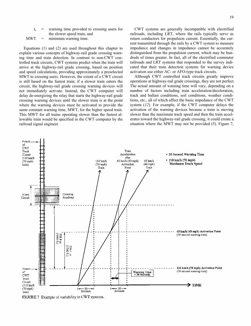
19
ts = warning time provided to crossing users for the slower speed train, and
MWT = minimum warning time.
Equations (1) and (2) are used throughout this chapter to explain various concepts of highway-rail grade crossing warn-ing time and train detection. In contrast to non-CWT con-trolled track circuits, CWT systems predict when the train will arrive at the highway-rail grade crossing, based on position and speed calculations, providing approximately a preselected MWT to crossing users. However, the extent of a CWT circuit is still based on the fastest train; if a slower train enters the circuit, the highway-rail grade crossing warning devices will not immediately activate. Instead, the CWT computer will delay de-energizing the relay that starts the highway-rail grade crossing warning devices until the slower train is at the point where the warning devices must be activated to provide the same constant warning time, MWT, for the higher speed train. This MWT for all trains operating slower than the fastest al-lowable train would be specified in the CWT computer by the railroad signal engineer.
CWT systems are generally incompatible with electrified railroads, including LRT, where the rails typically serve as return conductors for propulsion current. Essentially, the cur-rent transmitted through the rails by a CWT system to measure impedance and changes in impedance cannot be accurately distinguished from the propulsion current, which may be hun-dreds of times greater. In fact, all of the electrified commuter railroads and LRT systems that responded to the survey indi-cated that their train detection systems for warning device activation use either AC- or AFO-type track circuits.
Although CWT controlled track circuits greatly improve operations at highway-rail grade crossings, they are not perfect. The actual amount of warning time will vary, depending on a number of factors including train acceleration/deceleration, track and ballast conditions, soil conditions, weather condi-tions, etc., all of which affect the basic impedance of the CWT system (12). For example, if the CWT computer delays the activation of the warning devices because a train is moving slower than the maximum track speed and then the train accel-erates toward the highway-rail grade crossing, it could create a situation where the MWT may not be provided (5). Figure 7,
FIGURE 7 Example of variability in CWT systems.

20
which was developed for this synthesis to illustrate the point, depicts a train approaching a highway-rail grade crossing at two constant speeds, 110 km/h (70 mph) and 65 km/h (40 mph). If the train travels at the constant speed of 110 km/h (70 mph), 30 sec. of warning time will be provided to crossing users at the highway-rail grade crossing. Also, if the train travels at the constant speed of 65 km/h (40 mph), 30 sec. of warning time will be provided to crossing users at the high-way-rail grade crossing. However, if the train was originally traveling at 65 km/h (40 mph) and then accelerates after acti-vating the highway-rail grade crossing warning devices (as shown by the train trajectory between the 110 km/h (70 mph) and 65 km/h (40 mph) train trajectories), the warning time provided to crossing users will be less than the prescribed MWT of 30 sec. for this example. The Institute of Transporta-tion Engineers (ITE) Recommended Practice on the Preemp-tion of Traffic Signals At or Near Railroad Grade Crossings with Active Warning Devices recommends that railroads adopt an operating rule that prohibits train acceleration as it ap-proaches a crossing with active warning until the locomotive clears the crossing (5).
The results of a small study on the variability of warning times provided by CWT systems are presented in Figure 8. The study, by L-P Tardif & Associates, Parviainen & Associ-ates, and CANAC International, Inc. for the Transportation Association of Canada, was conducted at a highway-rail grade crossing immediately adjacent to a small railroad yard with both slow and fast freight trains and some switching maneu-vers. The figure illustrates that for the 68 trains traveling at speeds greater than 50 km/h (30 mph), warning times varied from a low of 12 sec. to a high of 38 sec., with the preponder-ance of times falling between 20 and 33 sec. (13).
Off-Track Train Detection
In some cases, highway-rail grade crossing warning devices are activated using off-track mechanisms. For railroads, a key-operated mechanism can be used to activate the warning de-vices. The train locomotive approaches the highway-rail grade crossing and then stops short of the actual roadway. A member of the train crew then inserts a key into a wayside selector. Once the warning devices are keyed to activate, which would also start the traffic signal preemption sequence at the nearby intersection, the train must wait for the MWT before proceed-ing through the highway-rail grade crossing.
For LRT, off-track detection systems include wayside pushbuttons, which are typically used where the LRV must stop at a station on the nearside of a highway-rail grade cross-ing. Once passengers have boarded and alighted and the LRV is almost ready to depart the station through the highway-rail grade crossing, the operator will push a wayside button (usu-ally accessible through the window of the LRV cab) to acti-vate the warning devices. Another common LRV detection system uses “trip” switches mounted on the overhead contact system (the power distribution system for the electrically powered LRVs); these switches are “tripped” by the LRV pan-tograph as the train passes.
Another common form of LRV detection is train-to-wayside control (TWC) systems. TWC communicates to the warning devices using loop detectors placed between the rails and LRV-borne transponders. The warning devices are either activated as the LRV passes over the loops or, if the LRV is stopped over a TWC loop in a nearside station, when the LRV operator pushes a button in the LRV cab. Typically, the LRV operator can also use the TWC system to select routes and
FIGURE 8 Distribution of warning times by CWT systems (13).

21
switching movements. In addition to activating the warning devices, all of these LRV detection systems would start the traffic signal preemption sequence at a nearby intersection.
When Calgary Transit opened their LRT system, LRV op-erators activated warning devices from nearside stations using wayside push buttons. Calgary Transit soon installed a TWC system, which offered greater flexibility for LRV operators, creating less delay for crossing users. For example, Calgary Transit’s TWC system allows LRV operators to deactivate the warning devices if excessive delay is experienced during a nearside station stop.
Other off-track train detection systems are currently being researched by various railroad companies, manufacturers, and universities in North America. Some ongoing experiments use video imaging technology to detect approaching trains while others use the sound of locomotive horns as the train ap-proaches the highway-rail grade crossing to activate the warn-ing devices. (Railroad operating rules generally require train crews to sound the locomotive horns on approach to all public highway-rail grade crossings.)
The Federal Railroad Administration (FRA) and AAR are evaluating wheel sensors to detect trains approaching the highway-rail grade crossing and/or trains within the island circuit. Their interest in such products stems from the advent of lighter aluminum rail cars and independently rotating rail car wheels, which makes shunting of standard track circuits more difficult. Based on information provided by the FRA and AAR, one of the wheel sensor products being evaluated is manufactured by Tiefenbach GmbH in Essen, Germany. Their system uses wheel sensors as axle counters in a count- in/count-out configuration for determining the presence of a train within the island circuit. The Tiefenbach system success-fully passed initial screening tests and is currently being tested in the field at three highway-rail grade crossings. The sensor activity is by magnetic induction that generates electrical pulses as a wheel flange travels past the sensor. Each axle counter senses wheels without actual physical contact inde-pendent of velocity and direction. Tiefenbach indicates a maximum detection speed of 250 km/h (155 mph) with no required minimum speed. Dual axle counters are placed both at the entrance and exit of the island circuit. As the entrance counters begin counting axles, train occupancy in the island circuit is established. Under normal operations, assuming no spurious effects, when the number of axles counted as entering the island circuit equals the number of axles exiting the island circuit, train exit from the island circuit is established, and the warning devices de-activate. Different scenarios where equality of counts is achieved due to failure of the wheel counters have been taken into account so that these anoma-lies would cause the warning devices to remain active. Re-moval and sabotage of the axle counters can also be detected by the system. A similar wheel detector-type system is also available from Honeywell’s Micro-switch Sensing and Con-trol Division.
Another off-track train detection system has been devel-oped by EVA Signal Corporation. The EVA system uses a se-ries of magnetometer probes buried just off the ballast at strate-gic points to detect train activity and location. The probes
detect warping of the earth’s magnetic field caused by the movement of the extreme mass of ferrous metal in the train. Using computer controlled logic, the probes can identify train direction, speed, length, etc., and can activate the highway-rail grade crossing warning devices. Because the system can detect train motion and speed, constant warning times are provided to crossing users. Because the probes can only detect motion, island protection is achieved using infrared beam sensors to detect the presence of a stopped train blocking the highway-rail grade crossing.
Other advanced off-track train detection systems activate warning devices using precision train location data and com-munications-based technology. The basic concepts of commu-nications-based train detection, as well as two state-of-the-art demonstration projects, are described in the last section of this chapter.
Highway-Rail Grade Crossing Warning Time
Track circuits are designed to provide a certain amount of warning time at the highway-rail grade crossing before the front of the train (or LRV) enters the crossing roadway. Al-though warning times should not be excessive, otherwise crossing users may ignore the warning, federal and state guidelines and regulations for warning time are specified in terms of minimum warning time (MWT) as used in the equa-tions above. Based on the fastest allowable train on a given track, Eq. (1) is used to determine how far the track circuit needs to extend from a given highway-rail grade crossing to provide the MWT. Per the MUTCD, “On tracks where trains operate at speeds of 20 mph or higher, circuits controlling automatic flashing light signals shall provide for a minimum operation of 20 seconds before arrival of any train on such track. On other tracks used for switching and assembling trains a means shall be provided to warn approaching highway traffic” (4). The FRA regulations address required minimum warning time in Title 49 Code of Federal Regulations (CFR), Part 234.225, “Activation of Warning Systems,” which states, “A highway/rail grade crossing warning system shall be main-tained to activate in accordance with the design of the warning system, but in no event shall it provide less than 20 seconds warning time before the grade crossing is occupied by rail traffic.” Further, the AAR Signal Manual of Recommended Practice (Part 3.3.10) defines MWT: “Warning devices shall operate for a minimum of 20 seconds before a train operating at maximum speed enters the crossing” (3).
In addition to the nationally mandated MWT of 20 sec., many states have adopted their own standards, reiterating the 20-sec. national minimum. For example, Illinois reiterates the 20-sec. MWT in two standards. The Illinois Requirements for Highway Grade Crossing Protection, Section VII, “Operating Time,” states, “All protection devices shall indicate the ap-proach of a train for not less than twenty (20) seconds before the arrival at the crossing of the fastest train operated over the crossing.” Furthermore, Title 92: Transportation; Chapter III: Illinois Commerce Commission; Subchapter C: Rail Carriers

22
and Highways; Part 1535: Crossings of Rail Carriers and Highways: Subpart C: Establishment, Construction, and Maintenance of Grade Crossings, at 1535.350, “Circuits,” states, “Automatic flashing light signals shall be arranged to indicate the approach of trains on all main tracks and on auxil-iary tracks included between the signals where the speed of trains approaching the crossing exceeds 5 mph, for not less than 20 seconds before the arrival at the crossing of the fastest train over the track” (12). The Public Utilities Commission of the State of California, General Order No. 75-C, Regulations Governing the Protection of Crossings at Grade of Roads, Highways and Streets with Railroads in the State of California, states, “Crossing signals at main and branch line crossings shall be actuated by trains approaching on main tracks ... for approximately 25 seconds with limits of from 20 to 30 sec-onds in advance of the normally fastest train operated over the crossing protected, except where special conditions prevail” (14).
Beyond specifying a standard for the MWT, some states have adopted a maximum time that the warning devices should activate prior to a train arriving at the highway-rail grade crossing for the fastest allowable train on the given track. If warning devices are activated too long before the arrival of a train, crossing users may assume that a train is not actually approaching and the warning devices or train detection system have malfunctioned. Maximum allowable warning time ap-plies only to the fastest allowable train on a given track; it does not apply to a slow train that enters a non-CWT con-trolled track circuit and keeps the warning devices activated longer than the maximum. For example, in Oregon the Rail-road Division Rules and Regulations of the Oregon Public Utility Commissioner (1985) states in Section 42-090, “... pro-tective devices and ‘wigwag’ devices shall be activated by approaching trains through control circuitry in such a manner as will provide a warning through continuous signal operation for a period of not less than 20 seconds nor more than 40 sec-onds before the arrival of a train traveling at the highest speed permissible over that particular track” (15).
To achieve the desired MWT, usually 20 to 30 sec., for crossing users at the highway-rail grade crossing, the actual length of the track circuit for train detection is slightly longer than that given by Eq. (1), by at least a few seconds to account for highway-rail grade crossing- and system-specific variables, such as the width of the crossing, equipment response time, safety buffer time, and/or time for traffic signal preemption.
Equations (3) and (4) from the AAR Signal Manual of Rec-ommended Practice show all of the additive factors that are considered in order to increase the MWT to obtain the total approach time, which is the time in seconds that is inserted into Eq. (1) in lieu of the MWT to actually obtain the MWT at the highway-rail grade crossing. In fact, if the total approach time is used in Eq. (1) to account for these highway-rail grade crossing- and system-specific variables, crossing users should experience approximately the MWT (plus perhaps a few sec-onds). If Eq. (1) were to be used with the MWT, the actual warning time experienced by the crossing user at the highway-rail grade crossing would be several seconds less than the MWT mandated by federal and state rules and regulations.
MWT + CT + AT + BT = total warning time (sec) (3)
Total warning time + PT = total approach time (sec) (4)
where
MWT = minimum warning time provided to crossing users,
CT = clearance time, AT = adjustment time, BT = buffer time, and PT = preemption time.
CT in Eq. (3) is the clearance time. The AAR Signal Man-ual of Recommended Practice states that the MWT of 20 sec. should be increased by one second for each 3.0 m (10 ft), or portion thereof, for a minimum track clearance distance greater than 10.7 m (35 ft). For a double-tracked railroad mainline with a minimum distance between track centerlines of 5.5 m (18 ft) (16), the minimum track clearance distance is approximately 11.7 m (38.4 ft). Thus, the MWT would be increased to 21 sec. AT in Eq. (3) is the adjustment time, which accounts for variables in equipment response, motion sensing and constant warning time devices, and automatic gate activation time. Automatic gates activate no less than 3 sec. after the flashing light signals activate. BT, the buffer time, is discretionary and according to the AAR Signal Manual of Recommended Practice, may be provided in addition to the MWT and the CT.
For highway-rail grade crossings located adjacent to a sig-nalized intersection, the traffic signal system may require ad-ditional time to terminate phases (e.g., pedestrian phases) and clear any queued motor vehicles off the tracks. PT is referred to as the preemption time in the AAR Signal Manual of Rec-ommended Practice. Although the flashing light signals and bells are required to remain active for at least the MWT (i.e., the approach track circuit needs to extend a distance from the highway-rail grade crossing to obtain the total warning time for the fastest train on the track), the flashing light signals and bells are not required to be active for the total approach time as defined in Eq. (4) above. Instead, for the purposes of the nearby traffic signal, the track circuits may need to detect an approaching train a distance equivalent to the total approach time for the fastest train; however, the flashing light signals and bells do not need to activate until the train is at a distance equivalent to the total warning time for the fastest train. This advance train detection (by a distance equivalent to PT for the fastest train) for the traffic signal system is discussed in a fol-lowing section of this chapter. PT is determined by the agency having authority over the highway traffic signal system at the nearby intersection.
(It should be noted that when the American Railway Engi-neering Association (AREA) became the American Railway Engineering and Maintenance-of-Way Association (AREMA), the new group acquired AAR’s Communication and Signaling section. As such, the Signal Manual of Recommended Prac-tice is undergoing review and revision. Some of the above terminology may change in new versions of the manual. The

23
latest draft of the Signal Manual of Recommended Practice, Section 3.3.10, renames AT, the adjustment time, as ERT, the equipment response time. PT has been renamed APT, the ad-vance preemption time, and defined: “The Highway Authority may require advance notification of an approaching train prior to activation of the highway crossing warning devices.”)
To determine the distance (in feet) a track circuit needs to extend from a highway-rail grade crossing, Eq. (5) below is used. Eq. (5) is the same as Eq. (1), taking into consideration the conversion between miles per hour and feet per second. The approach distance (in feet) obtained by Eq. (5) can be converted to meters by dividing by a factor of 3.281 (i.e., 3.281 ft is approximately equal to 1 m). If PT as described above is 0 sec. (i.e., the highway-rail grade crossing is not located near a signalized intersection or the traffic signal sys-tem does not need any additional time beyond the TWT), the total approach time in Eq. (5) becomes the TWT. The speed for the fastest train allowable on the track in question, rf, is used in Eq. (5).
approach distance (df, ft.) = total approach time (sec) × 1.466 × rf (mph) (5)
where
df = approach circuit distance for the fastest train operating on the track
rf = fastest allowable train speed for the track in question.
The AAR Signal Manual of Recommended Practice states that the approach distance for each track (in a multiple track situation) should be calculated separately. Further, the AAR Signal Manual of Recommended Practice allows the individ-ual railroad agencies and companies to change the above cal-culations as necessary (3).
The length of the approach track circuit, df, does not end exactly at the edge of the highway-rail grade crossing, but rather at the edge of the adjoining island track circuit. For electronic track circuits (i.e., those without insulated joints, such as AFO circuits), it is AAR recommended practice that the island circuit extends a minimum of 15.2 m (50 ft) beyond the edge of the highway-rail grade crossing (3). This addi-tional distance beyond the edge of the traveled-way accounts for variations in electronic island track circuits due to atmos-pheric conditions, soil conditions, type of rail traffic, etc. Most railroads operating in the United States extend electronic track circuits to between 15.2 m (50 ft) and 22.9 m (75 ft) beyond the edge of the roadway or sidewalk pavement. For example, if the crossing roadway consists of two 3.6-m (12-ft) lanes with two 2.4-m (8-ft) sidewalks, the total length of the island circuit would be 42.6 m (140 ft), assuming a 15.2-m (50-ft) extension beyond the edge of the traveled-way. For freight railroad operations, most track circuit manufacturers’ guide-lines also require the total length of the island circuit to be no shorter than about 36.6 m (120 ft). Even for the longest rail cars, at least two axles would be in the island circuit at all times, providing the necessary shunting.
Highway-Rail Grade Crossing Warning Time: A Hypothetical Study
To illustrate the variability in warning times associated with different train speeds and preselected MWT settings on a CWT-controlled system, the highway-rail grade crossing de-picted in Figure 9 is discussed as a hypothetical study. Figure 9 shows the west approach circuit for an eastbound train ex-tending 916.8 m (3,008 ft) from the island circuit. The limit of the CWT-controlled track circuit is defined by a termination shunt, which serves a function similar to insulated joints without actually breaking the rail. Finally, this study will illus-trate the concepts and limitations associated with CWT sys-tems.
The study focuses on two preselected MWT settings of 30 and 25 sec. and two train speeds of 110 km/h (70 mph) and 65 km/h (40 mph), for a total of four cases shown in Figure 9. As shown in Case 1 of Figure 9, the CWT system is designed to provide an MWT at the highway-rail grade crossing of about 25 sec., even with a preselected MWT setting of 30 sec., for a 110 km/h (70 mph) train, the fastest train allowed on the track in question. That is, for a 110 km/h (70 mph) train, the CWT system would have to respond instantaneously with termina-tion shunts at 916.8 m (3,008 ft) to provide a warning time of about 30 sec. at the highway-rail grade crossing. Instead, Case 1 of Figure 9 shows that the system needs approximately 4.8 sec. to measure the changing electrical impedance in the ap-proach track circuit, called the acquisition time (A), and re-spond by activating the highway-rail grade crossing warning systems, called the delay time (C). Per Eq. (3), this CWT sys-tem delay time, the acquisition time (A) plus the delay time (C) is known as the adjustment time (AT). For the purposes of this example, CT, the clearance time; BT, the buffer time; and PT, the preemption time, are assumed to be 0 sec.
Even if the preselected MWT setting is changed from 30 sec. to 25 sec., the warning time experienced by crossing users (D) would remain approximately constant, differing by only 1 sec for a 110 km/h- (70 mph-) train. As illustrated in Case 2 of Figure 9, the 1 sec. difference results when the CWT computer delays the activation of the warning devices in an attempt to provide exactly the 25 sec. preselected MWT setting, called the “No Activation” time (B). Thus, because of the AT factor in the CWT system, a preselected MWT setting of 30 sec. or 25 sec. provides approximately the same amount of warning time at the highway-rail grade crossing for a 110 km/h- (70 mph-) train. To provide the full 30 sec. of warning time, the length of the west approach circuit would need to be extended by approximately 150 m (490 ft).
On the other hand, Cases 3 and 4 of Figure 9 indicate that for slower speed train operations, the preselected MWT setting affects the warning time experienced by crossing users at the highway-rail grade crossing. AT, aquisition time (A) plus de-lay time (C), in Cases 2 and 3 remains the same as in Cases 1 and 2, 4.8 sec. For Case 3 with a 65 km/h- (40 mph-) train and a preselected MWT setting of 30 sec., the CWT computer delays the activation of the highway-rail grade crossing warning devices by 16 sec., providing 30.0 sec. of warning time at the highway-rail grade crossing. For Case 4 with a 65

24
CASE #1 #2 #3 #4
Train Speed, km/h (m/sec.) 110 (30.56)
110 (30.56)
65 (18.06)
65 (18.06)
Preselected Minimum Warning Time (MWT), sec. 30 25 30 25
Time, sec. 4 4 4 4 A. Acquisition
Distance, m 122.2 122.2 72.2 72.2
Time, sec. 0 1 16 21 B. No Activation
Distance, m 0 30.6 289.0 379.3
Time, sec. 0.8 0.8 0.8 0.8 C. Delay
Distance, m 24.4 24.4 14.4 14.4
Time, sec. 25.2 24.2 30.0 25.0 D. Actual Warning
Distance, m 770.2 739.6 541.2 450.9
FIGURE 9 Hypothetical warning times study (from (12)).
km/h- (40 mph-) train and a preselected MWT setting of 25 sec., the CWT computer delays the activation of the highwayrail grade crossing warning devices by 21 sec., providing 25.0 sec. of warning time at the highway-rail grade crossing. For a train traveling at 65 km/h (40 mph), the actual warning time provided at the highway-rail grade crossing is virtually the same as the preselected MWT setting that is input into the CWT computer.
This hypothetical example, which was developed for this synthesis to illustrate inputs and outputs of CWT systems, is similar to analyses conducted in the aftermath of the com-muter train-school bus collision in Fox River Grove, Illinois. One important lesson learned through the Fox River Grove tragedy is that CWT computers are designed to provide an
approximately uniform warning time, but the actual warning time can vary, depending on various factors mentioned above (12). Even in the hypothetical study illustrated in Figure 9, the actual warning time at the highway-rail grade crossing varied by more than 4 sec. for a 30-sec. preselected MWT setting, de-pending on the train’s approach speed. In any specific applica-tion, it is necessary to use principles that fit the local conditions.
Advance Train Detection
One method to provide advance train detection is to use standard track circuits that extend a distance beyond the two

25
standard approach track circuits. As described in the discus-sion with Eq. (3) and Eq. (4), an advance track circuit is typi-cally used to notify a nearby traffic signal system that a train is approaching before the standard approach track circuit acti-vates the warning devices. Traffic signals controlling a nearby intersection may require more than total warning time (Eq. (3)) to appropriately and safely allow a train to cross one (or more) approaches unimpeded by motor vehicles, bicycles, and pedestrians. In fact, in many cases, especially for heavy and long freight movements, trains are unable to slow or stop even if there is some sort of interference at the highway-rail grade crossing due to a nearby traffic signal. Thus, detecting trains far enough in advance using advance track circuits is critical for safe operation of traffic signals near highway-rail grade crossings.
The additional “train approaching” time beyond the TWT re-quired by the traffic signal system is called PT, or preemption time, in Eq. (4). PT is the difference between the total time re-quired for the traffic signal system to appropriately accommo-date a train and the TWT per Eq. (3), which essentially compen-sates for equipment and site-specific factors to provide the MWT at the highway-rail grade crossing. The calculation to determine the total time required for the traffic signal system to accommodate an approaching train is discussed in chapters 3 and 4. The traffic signal controller unit must enter preemption, terminating traffic movements currently being served, providing signal indications to clear any queued motor vehicles off the tracks. If the total time required for the traffic signal system to accommodate an approaching train is less than the TWT (Eq. (3)), then PT is assumed to be zero.
There are two methods to provide the additional time, PT. For non-CWT-controlled track circuits, the entire standard approach circuit could be extended from the highway-rail grade crossing island circuit the distance attained from Eq. (5), assuming the PT is greater than 0 sec. The traffic signals have sufficient time to respond and safely accommodate an ap-proaching train. However, the warning devices would also activate for the entire time period, providing a warning time in excess of the desired MWT. Although some additional warn-ing time may not present a problem, excessive warning times may encourage motorists to ignore the warning devices, and may violate state rules and regulations. “Fail-safe” timers can
be installed to delay the activation of the warning devices by some fixed amount of time after the train first enters the ex-tended track circuit.
A second method to provide the additional time, PT, using non-CWT-controlled track circuits is to install a separate track circuit ahead of the standard approach track circuit to provide advance preemption to the traffic signals. Using advance pre-emption, notification of an approaching train is forwarded to the traffic signal controller unit for a period of time prior to activating the warning devices. In this fashion, the traffic sig-nals near the highway-rail grade crossing are, in essence, warned ahead of time that a train is approaching (3).
For CWT-controlled track circuits, the termination shunt, which is the defining point for the end of the approach circuit, for a given approach is determined by Eq. (5). If PT is greater than 0 sec., the entire track circuit should be extended to allow the traffic signals to accommodate an approaching train. The CWT computer is able to forward the “train approaching” message to the traffic signal controller unit as soon as it can accurately determine the changes in track circuit impedance (after the AT from Eq. (3)). The CWT computer is also able to delay notifying the nearby traffic signal controller unit if a slow train is detected approaching the crossing. However, the highway-rail grade crossing warning devices will not activate until the CWT computer estimates that the preselected MWT setting will be provided to crossing users at the highway-rail grade crossing. As long as terminating shunts for the CWT system allow time to provide advance preemption (per Eq. (5)), the CWT computer is capable of notifying the nearby traffic signal system ahead of and independently from the highway-rail grade crossing warning devices.
Where necessary, many states are moving toward using ad-vance preemption to accommodate the additional time, PT. Table 3 shows a list of state departments of transportation, railroad companies/agencies, and light rail transit agencies that use advance preemption or are planning to use advance preemption to better accommodate traffic signal operations near highway-rail grade crossings. Most of the nonelectrified railroads are accomplishing advance preemption when re-quested by the local highway authority through the use of CWT-controlled track circuits as described above. Of the 24
TABLE 3 USE OF ADVANCE PREEMPTION
State Departments of Transportation (23 responses)
Railroad Companies/Agencies (15 responses)
Light Rail Transit Agencies (5 responses)
Connecticut Burlington Northern Sante Fe Calgary Transit (Alberta, Canada) Maryland Consolidated Rail (Conrail) Mass Transit Administration (Maryland) Michigan CSX Transportation Minnesota Kansas City Southern Missouri Long Island Rail Road New Jersey Massachusetts Bay Transportation Authority (MBTA) North Carolina Metro-North Railroad North Dakota New Jersey Transit Rail Ohio Norfolk Southern Oregon Northeast Illinois Regional Commuter Railroad (METRA) Wisconsin Southern California Regional Rail Authority (Metrolink)

26
state departments of transportation that responded to the ques-tion on the survey in 1997, 11 indicated that highway-rail grade crossings under their jurisdiction either have advance preemption or will have advance preemption in the future; 11 of 15 railroads indicated that they routinely provide advance preemption for the highway authority; and 2 of 5 LRT agen-cies provide advance preemption.
Traffic Signal Interconnection Circuit
Preemption of traffic signals requires an electrical circuit or interconnection between the highway-rail grade crossing warning system and the traffic signal controller assembly. The MUTCD states that the circuit to the traffic signal controller assembly is normally of the closed circuit type and energized through a contact of a relay controlled by the master highway-rail grade crossing warning system relay (this master relay is sometimes referred to as the XR) or CWT/motion sensor com-puter (4). When a train enters and shunts the approach track cir-cuit, or the advance track circuit, the master highway-rail grade crossing warning system relay de-energizes, de-energizing the pre-empt relay to the traffic signal controller assembly and initiat-ing the traffic signal preemption sequence to clear motor vehicles off the tracks. The interconnection circuit includes the physical wires or cables that run between the railroad equipment (train detection system, master highway-rail grade crossing warning system relay, etc.) and the traffic signal controller cabinet.
Illinois is considering requiring that interconnection circuits be supervised. Supervised interconnection circuits notify the traffic signal controller unit if there is a problem with the physical wires or cables that run between the railroad equip-ment and controller cabinet. According to the Illinois Depart-ment of Transportation, problems include excavation contrac-tors inadvertently digging up the wire/cable, causing it to sever or cross (short circuit). Under these conditions, without a supervised interconnection circuit, the traffic signals at the nearby intersection would respond as if a train were approach-ing the highway-rail grade crossing, clearing motor vehicles off the tracks and then disallowing any further traffic move-ments that conflict with the train until the preempt relay is re-energized. However, the relay would not re-energize until the interconnection wire/cable is repaired, which could take sev-eral hours or days. With a supervised interconnection circuit, the traffic signal controller unit detects the broken wir-ing/cabling and responds as programmed. One possible re-sponse includes first clearing the tracks and then displaying all-way flashing red signal indications. This traffic signal con-trol mode more quickly alerts local authorities that a problem exists and allows all traffic movements at the intersection to progress. It should be noted, that based on discussions with department of transportation representatives from California, Illinois, and Oregon, broken or crossed interconnection wire/cable is an exceptionally rare event.
Figures 10A through 10C illustrate a possible supervised in-terconnection circuit, as being proposed by Illinois. Each
FIGURE 10 Possible supervised interconnection circuit.

27
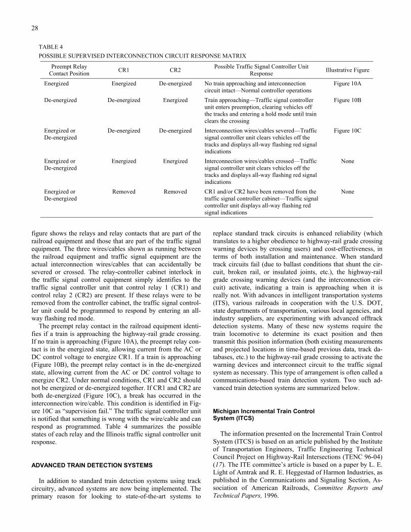
28
TABLE 4 POSSIBLE SUPERVISED INTERCONNECTION CIRCUIT RESPONSE MATRIX
Preempt Relay Contact Position CR1 CR2 Possible Traffic Signal Controller Unit
Response Illustrative Figure
Energized Energized De-energized No train approaching and interconnection circuit intact—Normal controller operations
Figure 10A
De-energized De-energized Energized Train approaching—Traffic signal controller unit enters preemption, clearing vehicles off the tracks and entering a hold mode until train clears the crossing
Figure 10B
Energized or De-energized
De-energized De-energized Interconnection wires/cables severed—Traffic signal controller unit clears vehicles off the tracks and displays all-way flashing red signal indications
Figure 10C
Energized or De-energized
Energized Energized Interconnection wires/cables crossed—Traffic signal controller unit clears vehicles off the tracks and displays all-way flashing red signal indications
None
Energized or De-energized
Removed Removed CR1 and/or CR2 have been removed from the traffic signal controller cabinet—Traffic signal controller unit displays all-way flashing red signal indications
None
figure shows the relays and relay contacts that are part of the railroad equipment and those that are part of the traffic signal equipment. The three wires/cables shown as running between the railroad equipment and traffic signal equipment are the actual interconnection wires/cables that can accidentally be severed or crossed. The relay-controller cabinet interlock in the traffic signal control equipment simply identifies to the traffic signal controller unit that control relay 1 (CR1) and control relay 2 (CR2) are present. If these relays were to be removed from the controller cabinet, the traffic signal control-ler unit could be programmed to respond by entering an all-way flashing red mode.
The preempt relay contact in the railroad equipment identi-fies if a train is approaching the highway-rail grade crossing. If no train is approaching (Figure 10A), the preempt relay con-tact is in the energized state, allowing current from the AC or DC control voltage to energize CR1. If a train is approaching (Figure 10B), the preempt relay contact is in the de-energized state, allowing current from the AC or DC control voltage to energize CR2. Under normal conditions, CR1 and CR2 should not be energized or de-energized together. If CR1 and CR2 are both de-energized (Figure 10C), a break has occurred in the interconnection wire/cable. This condition is identified in Fig-ure 10C as “supervision fail.” The traffic signal controller unit is notified that something is wrong with the wire/cable and can respond as programmed. Table 4 summarizes the possible states of each relay and the Illinois traffic signal controller unit response.
ADVANCED TRAIN DETECTION SYSTEMS
In addition to standard train detection systems using track circuitry, advanced systems are now being implemented. The primary reason for looking to state-of-the-art systems to
replace standard track circuits is enhanced reliability (which translates to a higher obedience to highway-rail grade crossing warning devices by crossing users) and cost-effectiveness, in terms of both installation and maintenance. When standard track circuits fail (due to ballast conditions that shunt the cir-cuit, broken rail, or insulated joints, etc.), the highway-rail grade crossing warning devices (and the interconnection cir-cuit) activate, indicating a train is approaching when it is really not. With advances in intelligent transportation systems (ITS), various railroads in cooperation with the U.S. DOT, state departments of transportation, various local agencies, and industry suppliers, are experimenting with advanced offtrack detection systems. Many of these new systems require the train locomotive to determine its exact position and then transmit this position information (both existing measurements and projected locations in time-based previous data, track da-tabases, etc.) to the highway-rail grade crossing to activate the warning devices and interconnect circuit to the traffic signal system as necessary. This type of arrangement is often called a communications-based train detection system. Two such ad-vanced train detection systems are summarized below.
Michigan Incremental Train Control System (ITCS)
The information presented on the Incremental Train Control System (ITCS) is based on an article published by the Institute of Transportation Engineers, Traffic Engineering Technical Council Project on Highway-Rail Intersections (TENC 96-04) (17). The ITE committee’s article is based on a paper by L. E. Light of Amtrak and R. E. Heggestad of Harmon Industries, as published in the Communications and Signaling Section, As-sociation of American Railroads, Committee Reports and Technical Papers, 1996.

29
Harmon Industries (a manufacturer of highway-rail grade crossing warning devices and train control systems), the FRA, Amtrak, and the Michigan Department of Transportation are implementing a new train control signaling system on a por-tion of the Chicago to Detroit rail corridor. Based on the Incre-mental Train Control System (ITCS) developed by Harmon Industries, the new system will allow high-speed passenger trains traveling up to 175 km/h (110 mph) to operate over track and through highway-rail grade crossings currently controlled by a signaling system (block and highway-rail grade crossing track circuits) set up for a maximum operating speed of 130 km/h (80 mph). The initial installation will cover about 80 km (50 mi) of Amtrak owned and operated track, including 53 pub-lic highway-rail grade crossings, currently equipped with flash-ing light signals and automatic gates, and about 25 private highway-rail grade crossings with no active warning devices.
The track circuit-based train detection system, which cur-rently notifies the highway-rail grade crossing warning de-vices (e.g., flashing light signals and automatic gates) of an approaching train, is set up to provide a specific amount of warning time (typically 20 to 30 sec.), based on the maximum allowable train speed on the tracks in question. To provide improved passenger rail service in this corridor at speeds up to 175 km/h (110 mph), the track circuits along the entire corri-dor would need to be lengthened in order to continue provid-ing the same amount of highway-rail grade crossing warning time. Extending all of the track circuits (e.g., moving insulated joints that are physically cut into the rail) would be a very costly solution for implementing high-speed passenger rail service. Therefore, this less costly system, described below, is being developed and tested in Michigan.
The ITCS will allow high-speed passenger trains to be de-tected before the standard track-based, train detection points, and thus the 20 to 30-sec. warning time will continue to be provided at all of the public highway-rail grade crossings. To accomplish early detection, each high-speed train will be equipped with a global positioning system (GPS) and other related electronics. When a high-speed train enters ITCS terri-tory, it will receive a track profile database from a wayside radio link. This track profile data contains all fixed speed lim-its, site-specific operating instructions, and locations of all relevant objects such as switches, wayside signals, highway-rail grade crossings, track gradients, etc. Using GPS, locomo-tive axle tachometers (for axle rotation speed measurements, which can be converted to distance based on wheel radii), and differential correction data (to account for any errors in non-military codes transmitted by the GPS satellites), on-board computers will match the train’s actual location with the digi-tal track map, allowing exact train position, speed, accelera-tion, etc. to be both known and forecast. Based on its present speed, location, acceleration, etc., a high-speed train will pre-dict its expected arrival time at highway-rail grade crossings well before the standard track circuit-based train detection points (usually 2 to 3 minutes prior) and transmit this arrival time estimate to computers located at each of the highway-rail grade crossings. The electronics at the highway-rail grade crossing will then determine when to activate the warning systems to provide the appropriate amount of warning time
(20 to 30 sec.). The electronics at the highway-rail grade crossing will also send a message back to the train’s on-board computer confirming that the warning systems are “armed” and ready to begin operating at the proper time.
If the train’s on-board computer does not receive an “armed” indication from the highway-rail grade crossing com-puter, the train will be forced to slow to the speed at which the existing track circuit-based, train detection system will pro-vide the 20 to 30 sec. of warning time. Further, certain fault conditions detected by the electronics at the highway-rail grade crossing will cause messages to be sent to the train that slow it even further.
To provide warning at the private highway-rail grade cross-ings along the corridor, a train-activated sign demonstration project is also being undertaken. Private highway-rail grade crossings will be equipped with a train-activated, warning sign displaying one of three messages: WAIT (red), WATCH (red), and CROSS (yellow). The signs will be controlled through existing track circuits (for the block signaling system) and “fail-safe” timers to optimize the message timing. The active sign displays the CROSS message when the track circuits are unoccupied (no train approaching). When the track circuit containing one of these signs is first occupied, a delay timer runs to allow the fastest train (in this case, 175 km/h (110 mph)) to reach a point about 40 sec. from the private highway-rail grade crossing, at which time the message on the sign changes to WAIT. A second timer is set to expire after allow-ing a slower train (around 65 km/h (40 mph)) to reach the crossing. At the expiration of this timer, if the track circuits are still occupied, the message changes to WATCH (17).
Pacific Northwest Positive Train Separation Project
The Positive Train Separation (PTS) project in the Pacific Northwest builds on initial tests by the Burlington Northern Sante Fe (BNSF) and Union Pacific (UP) railroads after a head-on collision between two trains belonging to each of the railroads. The PTS system tracks trains operating in the Pa-cific Northwest rail network continuously, in real-time using GPS satellites and other sensing technologies, such as transponders and locomotive axle tachometers. For the rail-roads, the primary purpose of PTS technology is to keep trains operating in the Pacific Northwest separated in time and space, to preclude the possibility of a train-train collision. However, because exact position and speed as well as pre-dicted positions and speeds must be known to implement full PTS, this same technology can be integrated with emerging ITS technology to provide a better train detection system for highway-rail grade crossings. Computers on-board each train determine its exact location, speed, and predicted arrival at a downstream highway-rail grade crossing. The local highway-rail grade crossing computer could then activate the warning systems to provide a specified amount of time before the train is predicted to arrive in the highway-rail grade crossing. Cur-rently, the Texas A&M University’s Texas Transportation Institute (TTI) is evaluating the reliability of this form of train

30
detection as compared to standard approach track circuits. TTI is also evaluating the feasibility of processing the precise train location data at an area-wide (or regional) control center, also known as a transportation management center (TMC). The TMC would then optimize traffic signal timing (splits, offsets, etc.) along corridors that cross the rail lines based on precise train location data, as well as activate the highway-rail grade crossing warning systems at the appropriate times (13).
One of the pieces of hardware that will make such a system possible is the intelligent crossing controller (ICC) currently
under development at TTI. The ICC will serve as the central communications link and processing center for all aspects of highway-rail grade crossing activity. The ICC will facilitate receiving precise train locations, activating the warning de-vices, as well as serving as a two-way communication link between the warning devices/train detection system and any nearby traffic signal controller assemblies. The ICC will also be able to interface with other devices in the field, such as video surveillance cameras, changeable message signs, as well as the TMC computers.

31
CHAPTER THREE
HIGHWAY TRAFFIC SIGNALS NEAR HIGHWAY-RAIL GRADE CROSSINGS
OVERVIEW
This chapter describes the characteristics of operations near highway-rail grade crossings. It presents the various types of traffic signal units and related software programs that are typi-cally interconnected with train detection systems for the pur-poses of preemption. This chapter also describes the sequence of events of both the highway-rail grade crossing warning devices and the nearby signals for both vehicles and pedestri-ans. It addresses when agencies typically preempt traffic sig-nals and the characteristics of traffic signal preemption. A brief discussion of advance traffic signals (pre-signals) and advance preemption is also included.
Highway Traffic Signals
According to the Manual on Uniform Traffic Control De-vices for Streets and Highways (MUTCD), “A highway traffic signal is any power-operated traffic control device, other than a barricade warning light or steady burning electric lamp, by which traffic is warned or directed to take some specific action. A traffic control signal (traffic signal) is a type of highway traffic signal by which traffic is alternately directed to stop and permitted to proceed” (4).
TRAFFIC SIGNAL PREEMPTION
The National Electrical Manufacturers Association (NEMA), Standards Publication No. TS 2, “Traffic Controller Assemblies,” defines preemption as the transfer from normal operation of the traffic signals to a special control mode (18). Based on an engineering study, traffic signals at intersections located near highway-rail grade crossings may need to be pre-empted when trains approach in order to clear motor vehicles off the tracks. Preemption of traffic signals is typically done when the traffic queue from the nearby intersection extends or would likely extend to the highway-rail grade crossing; i.e., vehicles stopped for red traffic signal indications may be queued back across the adjacent set of tracks (1). The vehicles stopped on the tracks need to be permitted to clear the tracks before a train arrives at the highway-rail grade crossing. In addition, vehicles stopped for trains may queue back into nearby intersections, blocking traffic flow. The objective of a successful preempt is to take control of the intersection traffic signal displays and provide for the passage of a train, no mat-ter where in the normal traffic signal operation the preempt occurs (19).
When to Preempt Traffic Signals
As identified in the MUTCD Section 8C-6, when the dis-tance between the highway-rail grade crossing and the signal-ized intersection is less than 60 m (200 ft), preemption should be considered (4). As indicated in over half a dozen survey responses, many state departments of transportation believe that the need for preemption should be based on a detailed queuing analysis, considering items such as roadway approach traffic volumes, number of lanes, nearby traffic signal timing, saturation flow rates, motor vehicle arrival characteristics, motor vehicle classes, etc., rather than a prespecified distance such as 60 m (200 ft). The Institute of Transportation Engi-neer’s (ITE) Recommended Practice on the Preemption of Traffic Signals At or Near Railroad Grade Crossings with Active Warning Devices highlights the need for preemption to be based on a detailed queuing analysis (5). Under certain conditions, traffic queues from a nearby intersection could extend well beyond 60 m (200 ft) and potentially cause stopped vehicles to become trapped on the tracks.
A paper by Oppenlander and Oppenlander relates vehicle queuing to hourly traffic volumes for each lane approaching an intersection (20). Table 5, using the Oppenlander research, shows how vehicles may be expected to queue under free flow traffic conditions. This example shows that an assumed 75 sec. cycle length with an effective green time of 30 sec. for a spe-cific approach can produce more than 38 vehicles in the queue. The sample calculation, which uses a design lane volume of 400 vehicles per hour, composed of an assumed vehicle classi-fication mix of 94 percent cars and 6 percent trucks, produces 10 vehicles in queue for a total distance of 80 m (262 ft). De-pending on conditions at the highway-rail grade crossing, high-volume approaches can develop queues extending be-yond 300 m (1,000 ft), significantly exceeding the 60-m (200-ft) limit indicated by the current MUTCD (4).
TYPES OF TRAFFIC SIGNAL CONTROLLER ASSEMBLIES
In the past, traffic signal controller assemblies were manu-factured and classified as pretimed, semi-actuated, or fully actuated. Traffic signals installed today are typically con-trolled by microprocessors, commonly referred to as state-of-the-art controller units. Current technology has permitted a single type of controller unit, which, using a microprocessor and a programmable read-only memory (PROM) integrated circuit, can provide the following three types of control, de-pending on the settings of the controller unit:
• Pretimed control,

32
TABLE 5 EXAMPLE OF EVALUATING HIGHWAY TRAFFIC QUEUES FOR TRAFFIC SIGNALS THAT REQUIRE PREEMPTION DUE TO NEARBY RAILROAD OPERATIONS (20)
Track Approach Design Lane Volume
(vph)
Highway Signal Cycle Length1: 75 Seconds Green Time on Railroad Approach2: 30 Seconds
Distance in Vehicle Units (queue length) 100 3 150 4 200 5 250 6 300 7 350 8 400 10 (See example below) 450 12 500 16 550 38
Example: Lane Volume = 400 vph Car = 25 ft, 94% of Volume Cycle Length = 75 sec. Single Unit Truck = 35 ft, 4% Volume Green Time on Railroad Approach = 30 sec. Truck Combination = 65 ft, 2% Volume
Distance in Vehicle Units
10 × [(0.94 × 25) + (0.04x35) + (0.02 × 65)] = 262 ft.
Notes: Distance may be derived from the predicted queue length (factored vehicle length); see example above. Queue length is based on simulation values, using a 95th percent confidence interval. Distance is measured from the intersection stop line to the railroad stop line (on the near side of the tracks), 1 foot = 0.3048 meters.
1Total of the maximum time settings for all conflicting phases, including green and clearance inter-vals, with traffic actuated operation.
2Total of the maximum time settings for the approach phase, including green and clearance intervals, with traffic actuated operation.
• Semi-actuated control, and • Fully actuated control.
Semi- or fully actuated control can be provided by any cur-rent traffic signal controller unit. Use of either type of control depends on various factors and mostly on the user preference. Most current signal controller units also allow users to imple-ment a security program to disallow unauthorized changes in traffic signal timing. This type of security feature, now being implemented by the Illinois Department of Transportation in the aftermath of the collision in Fox River Grove, is especially important where changes in traffic signal timing can directly affect safety of motor vehicles and pedestrians using the nearby highway-rail grade crossing.
Pretimed Control
This type of control operates according to a predetermined schedule. Functionally, it has a fixed cycle length, preset phase interval durations, and fixed interval sequence. This type of control is best suited for locations with predictable traffic vol-umes and patterns, such as downtown areas. Pretimed control provides a fixed amount of time for each traffic movement phase interval. Time allocated to pedestrian intervals are fixed as well, displaying WALK and DONT WALK indications with compatible traffic movements as appropriate. However, if pe-destrian indications are not provided at an intersection, yet
pedestrian activity exists, the vehicular movement intervals are set to account for minimum pedestrian walk and clearance times. Each movement can be divided into a number of dis-cretely timed intervals such as the green phase, WALK, flash-ing DONT WALK, yellow change, and all red clearance. The timing is fixed for each of the intervals regardless of vehicle or pedestrian demand.
There are two types of pretimed controller units: electrome-chanical and solid-state. The electro-mechanical design, which lacks a microprocessor for control, is composed of one or more dials driven by synchronous motors and a camshaft. Six of 31 state departments of transportation that responded to this question on the survey indicated that they still have some elec-tro-mechanical controller units that receive preemption from train detection systems. A pretimed controller unit may have one, two, or three dials providing up to three cycle lengths and/or cycle split combinations resulting in nine timing plans set by time of day. Electro-mechanical controller units offer the least amount of flexibility for preemption. The solid-state version of a pretimed controller unit is essentially a digital counter counting the 60-cycle line frequency transmitted by local power utilities.
Semi-Actuated Control
Semi-actuated control typically serves an intersection that has a “main street” that should receive green traffic signal

33
indications as much as possible, and a “side street” that should only be given enough green to service the low and somewhat unpredictable demand when it occurs. At such locations, de-tectors are placed on the side-street approaches only. Semi-actuated control operates with variable vehicular and pedes-trian timing, which depends on traffic volumes or the presence of pedestrians. Flows are determined by vehicular detectors placed under (e.g., inductive loop detectors) or over (e.g., ra-dar, video surveillance) the roadway or by pedestrian actuation of push buttons.
Fully Actuated Control
An actuated controller unit is said to operate in the fully ac-tuated control mode when all phases and approaches have motor vehicle and possibly pedestrian detection. This type of control operates with variable vehicular and pedestrian timing, which depends on traffic volumes or the presence of pedestri-ans. The flows are determined by vehicular detectors placed under (e.g., inductive loop detectors) or over (e.g., radar, video surveillance) the roadway or by pedestrian actuation of push buttons. There are, for all practical purposes, two types of ac-tuated control hardware: those that are designed to NEMA specifications and the Type 170/179/2070 controller units. The purpose of the NEMA standards is to provide a measure of uniformity and interchangeability in equipment purchased by highway authorities. In fact, 26 out of 31 state departments of transportation that responded to this question in the survey indicated that most of their controller units that are intercon-nected with highway-rail grade crossing warning systems comply with the NEMA standards described below. Twelve of the 31 agencies also use the Type 170 controller units, devel-oped jointly by New York and California in the 1970s. This controller unit uses a general-purpose microprocessor, with the type of control implemented by software. The Type 179 and Type 2070 are later models of the Type 170 controller unit.
Signal controller units manufactured according to NEMA TS 1 standards do not have internal preemption; i.e., these controller units are generally not capable of accommodating preemption without special outside control processes. How-ever, many manufacturers offer enhanced versions of the TS 1 signal controller unit that include internal preemption.
The current industry standard for both pretimed and actu-ated signal controller units—NEMA TS 2-1992—includes provisions for internal preemption. The preemption priority and routines can be furnished by the signal controller unit manufacturer or specified by the user (18).
The latest controller unit in the Model 170 family, the Model 2070 controller unit, which was developed by the Cali-fornia Department of Transportation (Caltrans) and the City of Los Angeles, includes various provisions for internal preemp-tion depending on the specific software packages being run by the microprocessor. The Model 2070 is an “open” platform Advanced Transportation Controller (ATC) that completely separates hardware from application software by defining a common controller unit hardware platform on which multiple application software packages from multiple developers can
operate. The Model 2070 evolved from the tremendously suc-cessful and still popular Model 170 controller unit.
The Model 2070’s design utilizes 32-bit microprocessor technology with more than 10 times the computing perform-ance of today’s fastest Model 170s. This controller unit’s memory expansion capabilities give it flexibility and capabili-ties in addressing current and future traffic management needs. This flexibility allows the Model 2070 to be customized for specific applications. For example, it is expected that plugin boards will be developed for closed circuit television and changeable message sign management.
TRAFFIC SIGNAL CONTROLLER UNIT PREEMPTION CHARACTERISTICS
The preemption characteristics for the Type 170/179/2070 and NEMA TS 2 that are relevant to the preemption of traffic signals near highway-rail grade crossings follow.
Model 170/179/2070 Preemption
Preemption routines for user-programmable Model 170, Model 179, and Model 2070 are defined by the particular op-erating program used in the traffic signal controller unit. The Caltrans operating program for the Model 170 signal control-ler unit includes six preemption routines, two of which, RR1 and RR2, are assigned to highway-rail grade crossing preemp-tion. RR1 and RR2 are served on a first-come-first-served basis. Neither has priority over the other, and either will com-plete its sequence once it is initiated. RR1 flashes red on all signal indications during the rail “hold” interval and RR2 permits normal operation of all traffic movements that do not cross the tracks (see discussion of the hold interval below) (5).
NEMA TS 2 Preemption
General
A TS 2 signal controller unit is capable of receiving six dif-ferent preemption inputs (e.g., rail, emergency vehicle, transit, etc.) and responding with at least six unique preemption se-quences. These are identified as Preempt 1 through Preempt 6. Although TS 2 prescribes preemption input priority with the assumption that Preempts 1 and 2 are assigned for rail preemption use, it does not describe the operation of any preemption sequence. Therefore, the user must either accept the assignment and operation of preemption routines as offered by the manufacturer or specify the desired assignment and operation for each installation (5,18).
Preemption Input Priority
TS 2 establishes the priority of preemption inputs with the assumption that Preempt 1 and Preempt 2 are to be used for

34
highway-rail grade crossing application and the remaining routines are to be used for emergency vehicle or transit appli-cation. Preempt 1 normally has priority over Preempt 2 and both have priority over all other preemption routines. The pri-ority of Preempt 1 over Preempt 2 can be canceled by program entry. If the priority is canceled and a Preempt 1 input is re-ceived while the Preempt 2 routine is active, the Preempt 2 routine will complete normally. The Preempt 1 routine will not begin until the Preempt 2 routine is completed and only if the demand still exists.
Signal Controller Unit Input Priority
A TS 2 signal controller unit has a fixed priority for ac-commodating inputs to the microprocessor as follows.
Automatic Flash—Automatic flash is a flashing operation resulting from input from a manual switch, a time switch, or system command, but not from an input from the malfunction management unit or conflict monitor unit (5).
All preemption routines normally have priority over auto-matic flash. A preemption input received while automatic flash is in effect will cause automatic flash to terminate nor-mally, after which the signal controller unit will enter the ap-propriate preemption sequence. For example, if a train ap-proaches the highway-rail grade crossing during the automatic flash operation, the preemption routine takes priority over the automatic flash and the controller unit will display signal indi-cations to clear motor vehicles off the tracks. This priority can be canceled by program entry, in which case automatic flash would continue in spite of preemption (5).
Start-Up Flash— Start-up flash is a flashing operation that may be programmed to occur prior to initialization, after elec-tric power is applied to the signal controller unit. Start-up flash always has priority over all preemption routines. If a preemp-tion input becomes active or is active during start-up flash, the signal controller unit will remain in the start-up flash condition for the duration of both the preemption demand and start-up flash time (5).
External Start—External start is an input that, when ener-gized, normally causes the signal controller unit to revert to its programmed initialization interval. External start always has priority over all preemption routines. However, if external start becomes active during a preemption routine, the preemp-tion will terminate and the signal controller unit will revert to start-up flash rather than the initialization condition. The sig-nal controller unit will maintain the start-up flash condition for the duration of external start, preemption demand, and start-up flash time (5).
Malfunction Management Unit (MMU) Flash—MMU flash is a flashing operation resulting from input from the MMU. MMU Flash always has priority over all preemption routines. Any preemption routine in service will be immediately termi-nated by MMU flash, and no preemption will be serviced while MMU flash is in effect. All signal heads display flashing red or flashing red/flashing yellow during MMU flash. Ac-cording to ITE’s Recommended Practice on the Preemption of Traffic Signals At or Near Railroad Grade Crossings with
Active Warning Devices, “If a traffic signal includes railroad preemption, all signal heads should display flashing red during MMU Flash” (5).
INTERCONNECTION CIRCUIT INTERFACE
As described in chapter 2, for the traffic signal controller unit to act on preemption inputs, an interconnection circuit is used to pass the “train approaching” message to the traffic signal con-troller unit. The interconnection circuit, which runs between the railroad equipment and the signal controller cabinet, connects to the signal controller microprocessor through plug-in boards. These boards serve to electrically isolate the various controller assembly inputs from the main microprocessor.
An issue raised in follow-up interviews with some state de-partment of transportation representatives is that these plug-in boards are typically labeled inconsistently or not labeled at all. A single cabinet for an actuated signal controller unit typically has many plug-in isolation boards for receiving inputs from pedestrian buttons, loop detectors, etc. Without an appropriate labeling system, confusion may result and incorrect inputs may be given to the traffic signal controller unit.
PREEMPTION SEQUENCE
All currently manufactured controller units provide the same basic preemption sequencing, in conformance with cur-rently accepted practice (20). This includes:
• Entry into preemption, • Termination of the interval in operation, • Clear track intervals (including clear track green), • Preemption hold intervals, and • Return to normal operations.
To illustrate basic preemption sequencing, Figure 11 shows a typical signalized intersection adjacent to a highway-rail grade crossing. It depicts the normal two-phase (ø) traffic sig-nal sequence along with the traffic signal heads that display red, yellow, and green circular indications to approaching motor-ists, including pedestrian signals. The traffic signal heads with the same ø number always display the same indication (red, yellow, or green) at the same time to approaching motorists. Under the normal sequence of operation shown in Figure 11, the signal heads marked with ø4 and ø8 normally display the same indication to approaching motorists, as do the ø2 and ø6 heads; i.e, northbound and southbound traffic move together and eastbound and westbound traffic move together under normal operation. This is called a two-phase signal operation, even though four controller unit phases are used to produce it.
Entry into Preemption
Because of the limited amount of time commonly available before the train arrives in the highway-rail grade crossing, rail

35

36
preemption sequences are usually initiated by the signal con-troller unit immediately upon notification of an approaching train (21). However, several signal controller units allow a choice between locking and nonlocking modes of operation, similar to that of inductive loop detectors. In the locking mode, the signal controller unit initiates preemption immediately, and once the sequence has been initiated, it cannot be shortened or aborted except as noted earlier for start-up flash, external start, or MMU flash. In the nonlocking mode, a programmable de-lay timer is initiated when the train is detected. If the rail pre-emption input is still present when the timer has expired, the preemption sequence is initiated as before. If the rail preemp-tion input is no longer there, as would be the case if the train had stopped, reversed directions, and moved outside the limits of the approach track circuit, the preemption sequence is not initiated and normal operation would continue (21).
Termination of the Interval in Operation
Before the clear track intervals are initiated, the controller unit must terminate the interval in operation. As illustrated in
Figure 12, this step in the preemption sequence, identified with the letter “P” for “preemption,” is the change from the normal sequence of operation to the clear track intervals. The following are some key issues that complicate this operation: a) minimum intervals, b) vehicle clearance intervals, and c) pe-destrian clearance intervals.
Minimum Intervals
In the event of preemption, most traffic signal controller units have the capability to provide a minimum green interval. This programmable minimum green time allows the user to input a minimum green that must be served before termination of the green interval. If ø4 and ø8 have just started before pre-emption (see Figure 11), motorists could start up and after a few seconds receive yellow then red traffic signal indications due to the preemption. This sequence may be confusing to motorists and could result in trapping motor vehicles in the intersection. If motor vehicles are trapped within the inter-section, it would be unsafe to initiate the clear track green interval.
Notes: 1) Refer to Figure 11 for intersection layout 2) Preemption Hold Interval:
- Allow ø6 (optional as local conditions permit) for fully actuated operation - Delete ø6 for pretimed operation, unless:
• Intervening streets or driveways between the tracks and intersection • Sufficient distance between the tracks and intersection (cannot clear queue during Clear Track Green)
- Allow ø2 with ø6 (optional as local conditions permit) if there is sufficient distance between the tracks and the intersection, and there are intervening streets or driveways
FIGURE 12 Preemption sequence for a two-phase traffic signal (from (5)).

37
Vehicle Clearance Intervals
The MUTCD requires that regular clearance intervals (i.e., yellow traffic signal indications) cannot be terminated or omit-ted and must be used during preemption (4). All of the state departments of transportation that responded to the survey believe that signal controller units should not permit the short-ening or elimination of vehicle clearance intervals at any point in the preemption sequence. For example, after a preemption is received by the signal controller unit and the minimum green interval is served for those traffic movements that con-flict with vehicles needing to clear the tracks, the signal con-troller unit should serve the standard clearance interval before switching to the clear track green interval (4). In the case of Figure 11, if a train is detected approaching while the northbound and southbound movements are proceeding (ø4 and ø8). both directions, after serving the minimum green, should receive standard yellow intervals before the clear track green interval.
Pedestrian Clearance Intervals
A common practice among agencies today is to abbreviate or omit the pedestrian clearance intervals in effect at the time of preemption to permit the clear track green interval as soon as possible. Nineteen of the 31 departments of transportation that responded to the survey currently implement such a prac-tice. This involves immediately terminating the WALK inter-val and implementing either the full, abbreviated, or no flash-ing DONT WALK interval. The MUTCD. Section 8C-6 states. “Preemption shall not cause any short vehicular clearances and all necessary vehicular clearances shall be provided. However, because of the relative hazards involved, pedestrian clearances may be abbreviated in order to provide the track clearance display as early as possible” (4). Of 28 states that responded to this question on the survey, the Illinois Depart-ment of Transportation was the only agency that installs signs to warn pedestrians that their signal time is shortened when a train approaches. The sign is shown in Figure 13 at the pedes-trian crossing across Algonquin Road and parallel to U.S. Route 14 where METRA/UP line passes through Fox River Grove. It reads as follows: CAUTION—WALK TIME SHORTENED WHEN TRAIN APPROACHES.
However, pedestrians may be placed at risk by abbreviating pedestrian clearance intervals. They may be caught off guard and have to make a quick decision on completing their cross-ing movement. Some state departments of transportation (7 of the 31 that responded to the survey) do not terminate or ab-breviate the pedestrian signal phases and let the termination process occur per the preset interval sequences. These agen-cies have provided enough advance train detection before a train arrives at the highway-rail grade crossing. With the changing policy context, more and more agencies are now terminating pedestrian clearance phases less abruptly. They now believe that it is important to detect an approaching train early enough to appropriately terminate pedestrian movements that conflict with motor vehicles needing to clear the tracks
FIGURE 13 Examples of pedestrian warning time signs.
(typically pedestrian movements crossing parallel to the rail alignment).
Some state departments of transportation (4 of the 30 sur-vey responses on this question) blank-out or turn off pedes-trian signals during the preemption sequence (required only if the traffic signal indications flash during the “hold” interval). However, many agencies are reconsidering the policy of blanking-out pedestrian signals when the rail preemption is received by the traffic signal controller unit. In fact, some agencies responded by indicating concern as to whether turning

38
the pedestrian indications off would be wise, as it could lead to confusion among crossing pedestrians as to what action is required of them. Sometimes, when blank-out occurs, pedes-trians are caught in the middle of the street, unsure of their crossing movement. The majority of the state departments of transportation surveyed (21 of 30 survey responses on this question) simply hold all pedestrian movements in the inter-section by displaying the DONT WALK indication or sym-bolic equivalent, if pedestrian signals are installed at all.
Clear Track Intervals
The key issues involving the clear track intervals are speci-fying the clear track signal indications and number of clear track intervals. Most of the controller units allow the user to specify which signal heads will display green indications dur-ing the clear track interval (21). For example, in Figure 12, only ø6 signal indications are selected for display during the clear track green interval. The other signal heads, ø2, ø4, and ø8, all display red signal indications to allow vehicles to clear off the tracks without conflict. Also, two separate clear track green intervals may be necessary in instances where the rail alignment crosses two different intersection approaches.
It is important for the length of the clear track green inter-val—the time necessary for a vehicle stopped on the tracks to safely clear the tracks—to account for the distance from the tracks to the signalized intersection, the start-up time charac-teristics of the vehicles in the queue within that distance, and the geometry of the highway-rail grade crossing. In general, an engineering study of the intersection/highway-rail grade cross-ing environment should determine the exact length of the clear track green interval (4). If the highway-rail grade crossing is a significant distance from the intersection, it may not be neces-sary to clear all traffic in that section, but only a sufficient distance for the queue to safely clear the tracks. This factor becomes very important if the tracks cut diagonally across two legs of the same signalized intersection.
ITE’s Recommended Practice on the Preemption of Traffic Signals At or Near Railroad Grade Crossings with Active Warning Devices indicates that “queue clearance time must be long enough to prevent premature display of a red traffic sig-nal for traffic clearing the tracks. If conditions allow, continue the queue clearance time beyond activation of railroad signal lights and gates—up to 5 seconds before train arrival” (5).
Twenty-nine of 31 state departments of transportation that responded on the survey indicated that they use standard green traffic signal indications, while 24 of 31 indicated that they use standard green traffic signal indications with green leftturn arrows to clear the tracks when a train approaches, with many states using both. Seven of 31 also use flashing red traffic sig-nal indications to clear the tracks. Most states that use this type of track clearance either have older controller units (e.g., electro-mechanical) or extremely low-volume roadways cross-ing the tracks. Two states use flashing yellow signal indica-tions to clear the tracks: Oregon and Maryland (one location). Oregon uses flashing yellow signal indications for track clear intervals when pedestrian clearance phases have to be
abbreviated for some reason. (See the Oregon example in chapter 4 for more details.)
Preemption Hold Intervals
Preemption hold intervals occur after the clear track inter-vals when the train is near or in the highway-rail grade cross-ing. During the hold intervals, most modern traffic signal con-troller units or controller software allow the signal indications to cycle, alternately serving conflicting traffic flows that do not conflict with the train movement through the highway-rail grade crossing. Newer signal controller units allow the user to select traffic movements that will be inhibited during the pre-emption. All other movements will be served as usual.
Nonconflicting pedestrian movements may also be serviced during hold intervals (21). It should be noted that in all states that responded, if the pedestrian signals were blanked-out dur-ing clearance intervals, they remained dark during the hold intervals.
Older traffic signal controller units, especially electro-mechanical models, are normally only capable of holding traf-fic with all red signal indications or some combination of flashing signal indications as described below. Some modified older signal controller units can accommodate limited service during the preemption hold intervals using external control modules.
After the queued vehicles are cleared off the tracks, locally specified control strategies may be used to accommodate spe-cial traffic conditions; however, the traffic signals typically switch to one of the control modes described below (1). Most of the survey respondents indicated that whatever control strategy is used it should be consistent throughout the jurisdic-tion to prevent confusion for motorists. All of the states that responded to the survey use one or more of the preemption hold intervals described next.
All Red
This control mode involves holding all motor vehicles until the train passes through the crossing. In Figure 11, ø2, ø4, ø6, and ø8 would be displaying red signal indications. This traffic signal control strategy is used only occasionally for signalized intersections located near highway-rail grade crossings. It will limit the intersection capacity or throughput. However, an all red hold interval is sometimes necessary where the tracks cut diagonally across two approach legs of the same signalized inter-section. In this case, there may be no traffic movements that are compatible with the train passage through the highway-rail grade crossing, depending on local geometry and other conditions.
Flashing All Red
This control mode allows motor vehicles to proceed through the intersection after coming to a complete stop at the stop line similar to an all-way STOP sign controlled intersection. This

39
traffic signal control mode allows motor vehicles traveling toward the highway-rail grade crossing to turn left or right onto the parallel roadway and allows motor vehicles traveling parallel to the rail alignment to cross the roadway that inter-sects with the tracks.
It may be confusing to motorists and would be very difficult to differentiate between the railroad flashing operation (during preemption) and late night flashing operation of the traffic signals (automatic flash). Furthermore, the traffic signals may go to all red flashing because of a malfunction, which motor-ists may confuse as a “train approaching” message if flashing all red is the preferred preemption hold phase.
Flashing Red/Flashing Yellow
This control mode provides flashing red signal indications for motorists traveling on the street crossing the tracks, ø2 and ø6 in Figure 11, and flashing yellow signal indications for the street running parallel to the tracks, ø4 and ø8 in Figure 11. This control mode allows motor vehicles on the street parallel to the tracks to cautiously proceed through the intersection and holds the motor vehicles on the street crossing the tracks. This traffic signal control mode allows motor vehicles traveling toward the highway-rail grade crossing to turn left or right onto the parallel roadway after stopping for conflicting traffic.
Limited Service
Under this traffic signal control mode, the traffic signals typically display green indications for motor vehicles traveling parallel to the rail alignment (ø4 and ø8 in Figure 11) and red aspects and turn restrictions for motor vehicles conflicting with the rail movement (ø2 and ø6 in Figure 11). If the pre-emption duration is long enough, the signals could also pro-vide limited service to those motor vehicles turning off the crossing roadway onto the parallel roadway at the signalized intersection (this would require the traffic signal to have pro-tected left turn phases).
In addition to serving ø4 and ø8 while the train is in the highway-rail grade crossing, it may also be possible to alter-nately serve ø4/ø8 and ø2/ø6, (Figure 12) with two distinct preemption hold intervals. As shown in Figure 12, this type of limited service operation is implemented as local conditions allow, typically where the distance between the signalized intersection and the highway-rail grade crossing allows for intervening streets and/or driveways. Also, if the traffic queue on the intersection approach that crosses the tracks is not fully served during the clear track green interval, it may be possible to alternately serve ø4/ø8 and ø6 without ø2 (ø2 would be served after the train clears the highway-rail grade crossing).
Return to Normal Operations
In returning to normal operations after a preemption se-quence, it may be desirable to return to a specific sequence of
intervals (21). It is reasonable to return and service first the traffic movements that were initially delayed by the train. But if one of the delayed movements is causing a queue to back up into an adjacent intersection, it would be desirable to service that movement as soon as possible.
If the return intervals serve traffic movements immediately following the movements that were interrupted by the train, some other movements could be extensively delayed. For ex-ample, on the San Diego light rail transit (LRT) system, mo-torists waiting to make a left turn from the street running par-allel to the tracks onto the street crossing the tracks experience long delays during return to normal operation. This is because priority is given to motorists on the street perpendicular to the tracks (both during preemption for track clearance and return-ing to normal operation to avoid spill back queues). This sometimes results in left-turning motorists becoming impatient and running the red traffic signal indication, especially during multiple successive preemptions. There is a tendency for these left-turning motorists to assume that the traffic signal is mal-functioning. They seem to accept the first movement being skipped, but are far less likely to accept their movement being skipped a second time (for a second light rail vehicle (LRV) movement) (22).
Another problem may occur if the traffic signal controller unit receives a second preemption input immediately follow-ing the release of the first preemption input. The second pre-emption input could be the result of a second train approach-ing the highway-rail grade crossing or a first train approaching after false activation of the warning devices. Some traffic sig-nal controller unit models cannot accept a second preemption input immediately after exiting to normal operation. In some cases, minimum intervals may be programmed in the software, not allowing the controller unit to proceed to the clear track intervals until after other movements are served for some pro-grammed amount of time. Based on various states’ experi-ences with this problem, one potential solution is to use ad-vance track circuit to sample for the second train, as described in chapter 2.
PREEMPTION COORDINATION EFFORTS
It is important for all railroad companies/agencies and highway authorities to establish clear communication proce-dures to coordinate all interconnection and preemption efforts (1). For example, the highway authority needs to notify the railroad agency of any changes to the traffic signal timing be-fore the changes are implemented, if the changes affect pre-emption sequence timing. Similarly, the railroad agency needs to notify the highway authority of any changes to the track circuits that detect trains approaching the highway-rail grade crossing, if the changes affect when the traffic signals will receive “train approaching” notification (2).
As a result of this heightened need for coordination and clear communication, some agencies have been implementing projects with mutual help and understanding for providing a safer environment to crossing users. For example, some high-way authorities, instead of relying solely on preemption,

40
attempt to keep the tracks clear at all times, whether or not a train is approaching, using traffic signal indications on the near side of the tracks.
If a signalized intersection is immediately adjacent to the highway-rail grade crossing, traffic signals could be installed on the near side of the highway-rail grade crossing, upstream of the traffic signals that control the intersection (see Figures 4 and 5) (1). When the train approaches the highway-rail grade crossing, the advance signals, referred to by the U.S. DOT’s Technical Working Group (TWG) as pre-signals, would turn red, stopping motor vehicles on the near side of the highway-rail grade crossing. The pre-signals would turn red before the traffic signals at the intersection (i.e., the downstream traffic signals), thereby clearing motor vehicles off the tracks and, at the same time, not allowing any more motor vehicles to move onto the tracks. An added benefit of pre-signals is that they can be operated in conjunction with the intersection signals so that on every signal cycle at the intersection, the pre-signals are designed to prevent queues from forming between the in-tersection stop line and the train tracks, whether or not a train is approaching the highway-rail grade crossing.
Two states that routinely use pre-signals are Michigan and South Carolina. The Michigan Department of Transportation indicated in their survey responses that it is unnecessary for them to preempt traffic signals to clear the track when a train
approaches. Using pre-signals, the track is cleared on every cycle. Michigan also indicated that it is not necessary to han-dle pedestrian signals any differently when a train approaches (as described above) because the traffic signals do not need to provide the track clearance intervals; therefore, pedestrian clearance phases do not need to be terminated or abbreviated. South Carolina also routinely uses pre-signals, especially at crossings that are equipped with flashing light signals but no automatic gate. (See the South Carolina example in chapter 4 for more details.) Neither of these states indicated in their sur-vey responses the legal/motor vehicle code ramifications of using pre-signals to keep the tracks clear. For example, if the pre-signals fail and their indications go dark (such as during a power outage), are motorists required by state law to stop in advance of the highway-rail grade crossing as they would at a dark signalized intersection or are motorists able to treat dark pre-signals similar to dark flashing light signals and proceed across the tracks without stopping?
Specific examples of how this coordination process relates to preemption and the actual implementation process for the interconnection of grade crossing warning/control systems and highway traffic signals are described in chapter 4. Also, three examples available from the survey responses illustrate inno-vative techniques used for the interconnection of train detec-tion systems and nearby traffic signals.

41
CHAPTER FOUR
INTERCONNECTION OF HIGHWAY-RAIL GRADE CROSSING WARNING/ CONTROL SYSTEMS AND HIGHWAY TRAFFIC SIGNALS
OVERVIEW
Chapter 2 of this report discussed highway-rail grade cross-ing warning and control systems, including why coordination between highway-rail grade crossings and nearby intersections controlled by traffic signals is necessary. Chapter 3 described traffic signal controllers and how they respond to a train ap-proaching an adjacent highway-rail grade crossing. The pur-pose of this chapter is to provide further details on how high-way-rail grade crossing warning and control systems and traf-fic signal systems need to work togther to provide a safe envi-ronment for crossing users. This chapter first describes the sequence of events at a highway-rail grade crossing relative to the sequence of events at a nearby signalized intersection. These two different sequences need to mesh together to function
as one, even though the two systems creating the two se-quences are only interconnected by a simple electrical circuit. The chapter concludes with examples of how three state de-partments of transportation have taken steps to allow these two independent systems to function better together to provide a safer environment for crossing users.
HIGHWAY-RAIL GRADE CROSSING AND TRAFFIC SIGNAL SYSTEM TIMING SEQUENCES
Table 6 presents a methodology based on the Institute of Transportation Engineers’ (ITE) Recommended Practice on the Preemption of Traffic Signals At or Near Railroad Grade
TABLE 6 SIGNALIZED INTERSECTION AND HIGHWAY-RAIL GRADE CROSSING TIME REQUIREMENTS COMPARISON TABLE (5)
I. Traffic Signal Maximum Preemption Time (1) II. Railroad (Or LRT) Warning Time (1) AT (Adjustment Time) (2) ________ sec. AT (Adjustment Time) (2) ________ sec. Traffic Signal Equipment Delay ________ sec.
Change & Clearance Intervals MWT (Min. Warning Time) 20 sec. Pedestrian Clearance (3) ________ sec. CT (Clearance Time) ________ sec. Min. Green, Conflicting Phase (4) ________ sec. BT (Buffer Time) ________ sec. Yellow Change ________ sec. Total Warning Time(9B) ________ sec. Red Clearance ________ sec.
Total ________ sec.
Clear Track Intervals (5) Dissipation of Queued Vehicles (6) ________ sec. Queue Clearance (7) ________ sec. Yellow Change ________ sec. Red Clearance ________ sec. Separation Time (8) ________ sec.
Total ________ sec.
Total Approach Time(9A) ________ sec (1)Time elements not used are set to 0 sec. (2)AT (or the Adjustment Time) accounts for the delay in rail equipment response; generally, it is the time from when the train enters the
approach track circuit to the time when the highway-rail grade crossing warning devices and/or traffic signal controller is notified. (3)If the WALK phase is allowed to continue after preemption is initiated, this time is also added. (4)This element is used if the pedestrian clearance is not present and the minimum green is not terminated immediately upon preemption. (5)Where railroad tracks diagonally cross two highways intersecting nearby, the procedure for Side I for Clear Track Intervals is repeated
for each approach and added to the Total Approach Time (9A). The time for the train to travel between the first highway-rail grade crossing and the second highway-rail grade crossing is typically subtracted from the Total Approach Time (9A).
(6)See the Institute of Transportation Engineers (ITE) Traffic Engineering Handbook (1992), pp. 76-77 (how to measure) and p. 120 to include start-up lost time (use 3 sec.) (5).
(7)Time required for a design vehicle (typically some type of standard truck or bus) in a standing (not moving) queue to accelerate from the stop line at the tracks, achieve proper speed, and traverse the minimum track clearance distance.
(8)The component of the maximum preemption time during which the minimum track clearance distance is clear of vehicular traffic prior to the arrival of the train (2).
(9A,B)The larger of the Total Approach Time (Side I) or Total Warning Time (Side II) is used to determine the extent of the approach track circuit. If Side I is greater than Side II, the difference (Side I minus Side II) is known as the Preemption Time, PT (3).
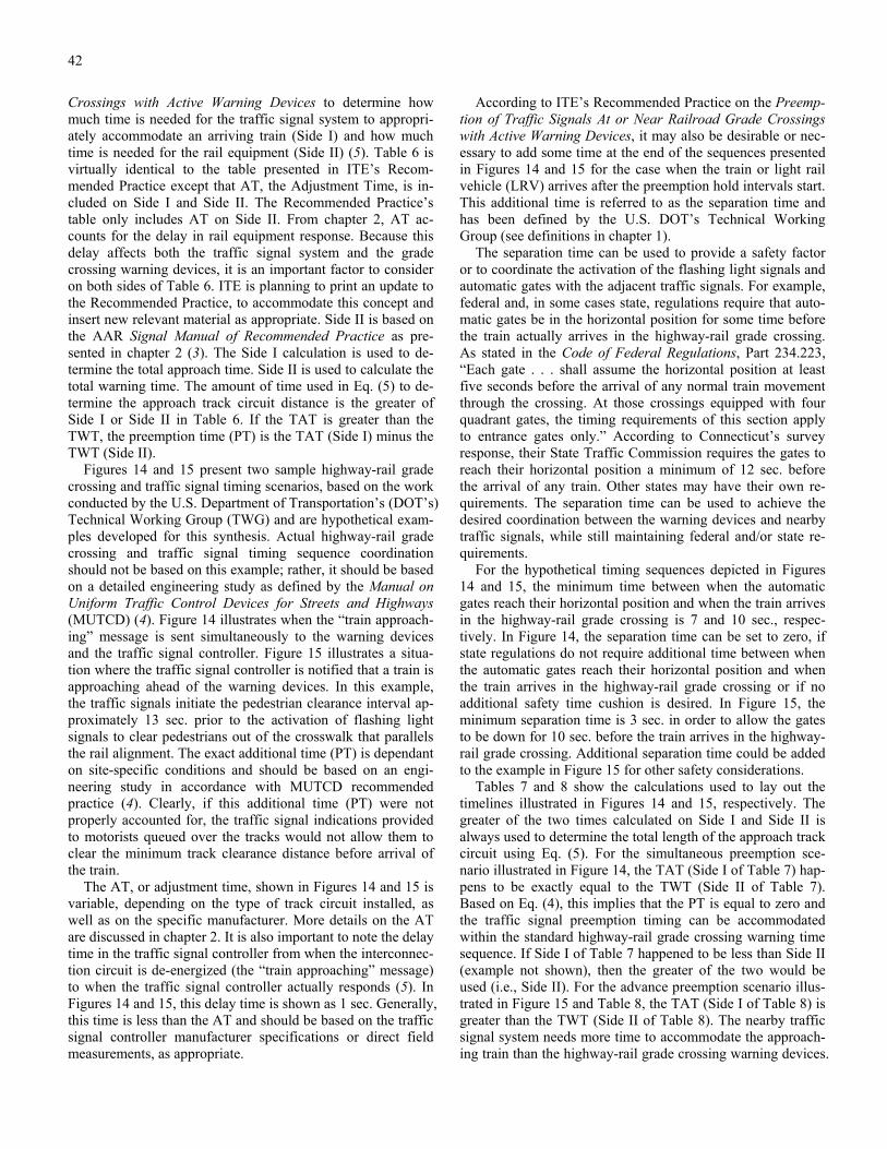
42
Crossings with Active Warning Devices to determine how much time is needed for the traffic signal system to appropri-ately accommodate an arriving train (Side I) and how much time is needed for the rail equipment (Side II) (5). Table 6 is virtually identical to the table presented in ITE’s Recom-mended Practice except that AT, the Adjustment Time, is in-cluded on Side I and Side II. The Recommended Practice’s table only includes AT on Side II. From chapter 2, AT ac-counts for the delay in rail equipment response. Because this delay affects both the traffic signal system and the grade crossing warning devices, it is an important factor to consider on both sides of Table 6. ITE is planning to print an update to the Recommended Practice, to accommodate this concept and insert new relevant material as appropriate. Side II is based on the AAR Signal Manual of Recommended Practice as pre-sented in chapter 2 (3). The Side I calculation is used to de-termine the total approach time. Side II is used to calculate the total warning time. The amount of time used in Eq. (5) to de-termine the approach track circuit distance is the greater of Side I or Side II in Table 6. If the TAT is greater than the TWT, the preemption time (PT) is the TAT (Side I) minus the TWT (Side II).
Figures 14 and 15 present two sample highway-rail grade crossing and traffic signal timing scenarios, based on the work conducted by the U.S. Department of Transportation’s (DOT’s) Technical Working Group (TWG) and are hypothetical exam-ples developed for this synthesis. Actual highway-rail grade crossing and traffic signal timing sequence coordination should not be based on this example; rather, it should be based on a detailed engineering study as defined by the Manual on Uniform Traffic Control Devices for Streets and Highways (MUTCD) (4). Figure 14 illustrates when the “train approach-ing” message is sent simultaneously to the warning devices and the traffic signal controller. Figure 15 illustrates a situa-tion where the traffic signal controller is notified that a train is approaching ahead of the warning devices. In this example, the traffic signals initiate the pedestrian clearance interval ap-proximately 13 sec. prior to the activation of flashing light signals to clear pedestrians out of the crosswalk that parallels the rail alignment. The exact additional time (PT) is dependant on site-specific conditions and should be based on an engi-neering study in accordance with MUTCD recommended practice (4). Clearly, if this additional time (PT) were not properly accounted for, the traffic signal indications provided to motorists queued over the tracks would not allow them to clear the minimum track clearance distance before arrival of the train.
The AT, or adjustment time, shown in Figures 14 and 15 is variable, depending on the type of track circuit installed, as well as on the specific manufacturer. More details on the AT are discussed in chapter 2. It is also important to note the delay time in the traffic signal controller from when the interconnec-tion circuit is de-energized (the “train approaching” message) to when the traffic signal controller actually responds (5). In Figures 14 and 15, this delay time is shown as 1 sec. Generally, this time is less than the AT and should be based on the traffic signal controller manufacturer specifications or direct field measurements, as appropriate.
According to ITE’s Recommended Practice on the Preemp-tion of Traffic Signals At or Near Railroad Grade Crossings with Active Warning Devices, it may also be desirable or nec-essary to add some time at the end of the sequences presented in Figures 14 and 15 for the case when the train or light rail vehicle (LRV) arrives after the preemption hold intervals start. This additional time is referred to as the separation time and has been defined by the U.S. DOT’s Technical Working Group (see definitions in chapter 1).
The separation time can be used to provide a safety factor or to coordinate the activation of the flashing light signals and automatic gates with the adjacent traffic signals. For example, federal and, in some cases state, regulations require that auto-matic gates be in the horizontal position for some time before the train actually arrives in the highway-rail grade crossing. As stated in the Code of Federal Regulations, Part 234.223, “Each gate . . . shall assume the horizontal position at least five seconds before the arrival of any normal train movement through the crossing. At those crossings equipped with four quadrant gates, the timing requirements of this section apply to entrance gates only.” According to Connecticut’s survey response, their State Traffic Commission requires the gates to reach their horizontal position a minimum of 12 sec. before the arrival of any train. Other states may have their own re-quirements. The separation time can be used to achieve the desired coordination between the warning devices and nearby traffic signals, while still maintaining federal and/or state re-quirements.
For the hypothetical timing sequences depicted in Figures 14 and 15, the minimum time between when the automatic gates reach their horizontal position and when the train arrives in the highway-rail grade crossing is 7 and 10 sec., respec-tively. In Figure 14, the separation time can be set to zero, if state regulations do not require additional time between when the automatic gates reach their horizontal position and when the train arrives in the highway-rail grade crossing or if no additional safety time cushion is desired. In Figure 15, the minimum separation time is 3 sec. in order to allow the gates to be down for 10 sec. before the train arrives in the highway-rail grade crossing. Additional separation time could be added to the example in Figure 15 for other safety considerations.
Tables 7 and 8 show the calculations used to lay out the timelines illustrated in Figures 14 and 15, respectively. The greater of the two times calculated on Side I and Side II is always used to determine the total length of the approach track circuit using Eq. (5). For the simultaneous preemption sce-nario illustrated in Figure 14, the TAT (Side I of Table 7) hap-pens to be exactly equal to the TWT (Side II of Table 7). Based on Eq. (4), this implies that the PT is equal to zero and the traffic signal preemption timing can be accommodated within the standard highway-rail grade crossing warning time sequence. If Side I of Table 7 happened to be less than Side II (example not shown), then the greater of the two would be used (i.e., Side II). For the advance preemption scenario illus-trated in Figure 15 and Table 8, the TAT (Side I of Table 8) is greater than the TWT (Side II of Table 8). The nearby traffic signal system needs more time to accommodate the approach-ing train than the highway-rail grade crossing warning devices.

43

44

45
TABLE 7 CALCULATIONS FOR THE SCENARIO PRESENTED IN FIGURE 14
I. Traffic Signal Maximum Preemption Time II. Railroad (or LRT) Warning Time AT (Adjustment Time) 6 sec. AT (Adjustment Time) 6 sec. Traffic Signal Equipment Delay 1 sec.
Change & Clearance Intervals MWT (Min. Warning Time) 20 sec. Pedestrian Clearance 0 sec. CT (Clearance Time) 0 sec. Min. Green, Conflicting Phase 2 sec. BT (Buffer Time) 0 sec. Yellow Change 3 sec. Total Warning Time 26 sec. Red Clearance 0 sec. Total 12 sec.
Clear Track Intervals Dissipation of Queued Vehicles 5 sec. Queue Clearance 4 sec. Yellow Change 4 sec. Red Clearance 1 sec. Separation Time 0 sec.
Total 14 sec.
(Total Approach Time) 26 sec.
TABLE 8 CALCULATIONS FOR THE SCENARIO PRESENTED IN FIGURE 15
I. Traffic Signal Maximum Preemption Time II. Railroad (or LRT) Warning Time AT (Adjustment Time) 6 sec. AT (Adjustment Time) 6 sec. Traffic Signal Equipment Delay 1 sec.
Change & Clearance Intervals MWT (Min. Warning Time) 20 sec. Pedestrian Clearance 12 sec. CT (Clearance Time) 0 sec. Min. Green, Conflicting Phase 0 sec. BT (Buffer Time) 0 sec. Yellow Change 3 sec. Total Warning Time 26 sec. Red Clearance 1 sec. Total 23 sec.
Clear Track Intervals Dissipation of Queued Vehicles 5 sec. Queue Clearance 4 sec. Yellow Change 4 sec. Red Clearance 1 sec. Separation Time 3 sec.
Total 17 sec.
(Total Approach Time) 40 sec.
PT is greater than zero and equal to the TAT minus the TWT (or 40 sec. minus 26 sec., or 14 sec.). The approach track cir-cuit needs to be extended by 14 sec. for the fastest allowable train on the track in question to safely accommodate the nearby traffic signal system.
EXAMPLES OF INTERCONNECTION, PREEMPTION, AND AGENCY COORDINATION
The interconnection of a train detection system and a traffic signal control system for the purpose of preemption takes
coordination on the part of several responsible authorities. Coordination is required between more parties than just the railroad company/agency (or LRT agency) and the highway authority. For example, on the Los Angeles light rail transit system (the Metro Blue Line), which is operated by the Los Angeles County Metropolitan Transportation Authority (LACMTA), a highway-rail grade crossing coordination effort involves 1) LACMTA staff (e.g., safety, design, construction, and operations personnel), 2) the local city and/or county traf-fic engineer, 3) a representative of the California Public Utili-ties Commission (which has jurisdiction over most highway-rail grade crossings in California), and 4) a representative of

46
the Union Pacific Railroad (which parallels LACMTA’s right-of-way between Los Angeles and Long Beach).
The following three examples illustrate various approaches to interconnection, preemption, and interagency coordination in three states: Oregon, South Carolina, and Wisconsin.
Oregon
Oregon, through its department of transportation, has de-veloped several policies to improve the safety of highway-rail grade crossings located adjacent to signalized intersections. For example, the Oregon Department of Transportation Traf-fic Management Section’s Traffic Signal Guidelines requires the following with regard to railroad preemption:
a) Preemption is required when tracks are 200 ft. [60 m] or less (as defined by the PUC) from a signalized intersection.
b) Indication for track clearance phase shall be green. c) Advance detection on the railroad is required to inhibit
pedestrian phases and to provide for complete timing of any pedestrian clearance interval (23).
The Traffic Signal Guidelines also allows the following combination:
a) Indication for track clearance may be flashing yellow. (For use when proper pedestrian clearance cannot be assured with green clearance.)
b) “PROCEED ON FLASHING YELLOW” fiberoptic sign is displayed during flashing yellow track clearance phase (23).
In addition to these standards, the Oregon Public Utility Commissioner (Section 42-116 of the Railroad Division Rules and Regulations of the Oregon Public Utility Commissioner) requires that all public authorities responsible for maintaining a traffic signal system that is interconnected with active high-way-rail grade crossing warning systems place the following message inside the traffic signal controller cabinet. The exact wording states: “IN CASE OF FAILURE OF RAILROAD PREEMPTION FEATURE WHICH CANNOT BE REPAIRED WITHIN 30 MINUTES, CALL THE RAILROAD DISPATCHER AT (telephone number) AND NOTIFY HIM OF THE PROBLEM AND EXPECTED DURATION. ALSO NOTIFY DISPATCHER WHEN REPAIRS ARE COMPLETED.” Train crews operating through a highway-rail grade crossing near where a traffic signal preemption system is malfunctioning will be aware that motor vehicles may be queued across the tracks because they may not be receiving green (or yellow) track clearance signal indications. Oregon is also imple-menting a practice recommended by the DOT’s TWG to place a new sticker in the railroad equipment cabinet and the traffic signal controller that give additional information about the intercon-nected crossing. Oregon’s new sticker is shown in Figure 16.
Additionally, all public authorities with jurisdiction over in-terconnected traffic signal equipment are responsible for in-stalling DO NOT STOP ON TRACKS signs capable of
holding three red flags. When the railroad preemption feature fails and cannot be repaired within 30 minutes, three flags are to be installed on top of the DO NOT STOP ON TRACKS sign, alerting motorists to the increased risk at the highway-rail grade crossing. This requirement is in addition to notifica-tion of the appropriate railroad. As an option to installing the three flags above the DO NOT STOP ON TRACKS sign, the traffic authority may provide manual flagging at the highway-rail grade crossing with the malfunctioning interconnect cir-cuit (24).
South Carolina
South Carolina uses pre-signals to keep the highway-rail grade crossing clear of motor vehicle traffic that may be queued back from a nearby signalized intersection. The South Carolina Manual on Uniform Traffic Control Devices pro-vides illustrations and sample traffic signal phasing plans for the implementation of pre-signals (see chapter 3). Figure 4-3.1, entitled “Typical Preemption Sequence,” in the South Caro-lina Manual on Uniform Traffic Control Devices, states that pre-signals are to be mounted on the near side of the tracks over the roadway lanes using spanwire (25). South Carolina uses pre-signals in two modes:
1) Under normal operations (i.e., when a train is not ap-proaching the highway-rail grade crossing), the pre-signals change to red indications several seconds before the down-stream signals at the intersection, clearing the minimum track clearance distance (and the clear storage distance if it is relatively short) on every signal cycle. When a train pre-empts the normal operations of the intersection traffic sig-nals, the time difference between when the pre-signals and downstream traffic signals change to red indications is in-creased, allowing an additional safety factor for motorists to clear the tracks before the train arrives.
2) Under normal operations, the pre-signals rest in flashing yellow and the intersection traffic signals (downstream) function normally. Per the Uniform Vehicle Code, Section 11-204, “When a yellow lens is illuminated with rapid in-termittent flashes, drivers of vehicles may proceed through the intersection or past such signal only with caution” (8). When a train preempts the normal operations of the inter-section traffic signals, the pre-signals change to solid yel-low indications while the downstream traffic signal indica-tions display solid green. The presignals then change to solid red indications while the downstream intersection traffic signals remain green, clearing the minimum track clearance distance. With the pre-signal indications red, the downstream traffic signal indications change through yel-low to flashing red, still allowing motorists to clear the clear storage distance after coming to a complete stop (25).
The survey response from South Carolina indicates that state traffic engineers generally install pre-signals at all high-way-rail grade crossings that are equipped with flashing light signals and not automatic gates. The pre-signals function like automatic gates when a train approaches: the pre-signals pro-hibit motor vehicles from entering the minimum track clear-ance distance while downstream traffic signals display green indications to clear queued motor vehicles off the tracks. Fur-ther, when the first pre-signal mode is used as described

47
FIGURE 16 Oregon Department of Transportation cabinet sticker.
above, South Carolina traffic engineers indicated that if the pre-signals are enforced by law officers, pre-signals have ac-tually trained many motorists to never stop their vehicle on the tracks, regardless of whether or not a train is approaching. The Traffic Control Devices Handbook (a guidebook to augment the Manual on Uniform Traffic Control Devices for Streets and Highways) also addresses the use of pre-signals at high-way-rail grade crossings in Section 8B-2, Figure 8-32, entitled, “Use of Additional Traffic Control Signals At Crossing” (26).
Wisconsin
Wisconsin has developed guidelines for all aspects of highway-rail grade crossing design and operation, including
those highway-rail grade crossings located adjacent to nearby signalized intersections. Wisconsin’s department of transportation has included many guidelines concerning high-way-rail grade crossings in its Facilities Development Manual. Specific guidelines and warrants exist in this manual for installing devices such as train-activated flashing light signals, auxiliary cantilevered flashing light signals, automatic gates, types of train detection, grade separations (overpasses or un-derpasses), and highway-rail grade crossing surface improve-ments. Most of the guidelines are either based on exposure (i.e., the product of average daily traffic (ADT) and trains per day through the highway-rail grade crossing) or other criteria, such as sight distance/visibility, accident history, type of train movements, etc.

48
The Facilities Development Manual in Chapter 17 (Rail-road Crossings), Section 40 (Design), Subject 15 (Warning Devices and Systems), known as Procedure 17-40-15, de-scribes in detail the various types of approach track circuits (described in chapter 2 of this report), as well as the preemp-tion of traffic signals at intersections adjacent to highway-rail grade crossings:
Preemption of traffic control signals involves the coordinated operation of highway traffic signal equipment and railroad grade crossing warning systems so that the approach of a train will cause the traffic signals to provide indications that will permit roadway traffic to clear the crossing before the arrival of a train. Preemption generally is used when a signalized intersection ex-ists within 200 feet [60 m] of a grade crossing. Information from the crossing warning system as to the approach of a train always takes precedence over the normal operation of the traffic signal.
Preemption is accomplished by interconnecting the control equipment of the two systems such that the signals of both systems do not display conflicting or confusing indications to the motorist. The objective of preemption is, first, to permit all roadway traffic to clear the crossing before the train arrives and, second, to allow parallel roadway traffic to flow while the train is occupying the crossing. “No Turn” signs, blank out signs, and signal indications should be provided to prevent mo-torists from turning toward the track during the train
movement. Where feasible, the location, normal phasing, and timing of traffic signals near a railroad crossing are designed so that vehicles are not required to stop on the tracks even though no trains are present in the area. When a train has cleared the crossing, the traffic signals resume their normal operation (27).
In addition to planning and design guidelines, the Wiscon-sin Department of Transportation takes a proactive role in coordinating field operations relative to interconnection and preemption. All highway-rail grade crossings under Wisconsin Department of Transportation jurisdiction where the train de-tection system is interconnected with nearby traffic signals, the following notice, printed on a bright yellow sticker, is placed in both the traffic signal controller cabinet as well as the railroad equipment cabinet. The exact wording states: “WARNING--This device is part of an Interconnect/Pre-empt Highway and Railroad Signal System. Any change in one sys-tem could affect the safe operation of the combined system. DO NOT make any modifications that could affect the opera-tion of the system without coordinating with the appropriate parties.”
It should be noted that both the Oregon and Wisconsin De-partments of Transportation have implemented practices that point to the absolute need for coordination among all parties involved with the operation of highway-rail grade crossings.

49
CHAPTER FIVE
CONCLUSIONS
The subject of traffic signal operations near highway-rail grade crossings is a topic of great interest to most state de-partments of transportation, local highway agencies, railroad companies and agencies, and light rail transit agencies. A sur-vey of these agencies indicated that 1) practices relative to traffic signal operations near highway-rail grade crossings vary widely throughout North America, and 2) coordination efforts between the railroad company/agency or light rail tran-sit agency and the highway authority also vary among jurisdic-tions. Coordination among these parties is the key to providing at least a minimum level of safety for crossing users, including motorists, pedestrians, bicyclists, and train operators. After the fatal commuter train-school bus collision in Fox River Grove, Illinois, much work has been performed by many parties to improve on traffic signal operations near highway-rail grade crossings.
In an effort to improve both safety and mobility at highway-rail grade crossings, many new concepts are being explored and researched.
• Advanced train detection systems are currently under de-velopment, using equipment such as the global positioning sys-tem (GPS) satellites, train-to-wayside communication links, positioning transponders, inertial navigation systems, etc. As more accurate train position information becomes available, traffic signal systems that are adjacent to highway-rail grade crossings could be equipped to accept more detailed data about train position, speed, and estimated time to crossing. With this data, the traffic signal controller would be able to accommodate train movements without the abrupt preemption process, im-proving highway-rail grade crossing safety and efficiency. Us-ing advanced, off-track train detection, an example system cur-rently being developed by the Texas Transportation Institute (under contract to the U.S. DOT) is the intelligent crossing con-troller. With this controller, all movements (both trains and mo-tor vehicles) through highway-rail grade crossings should be able to be coordinated and controlled.
Other off-track train detection systems that are currently be-ing evaluated by the Federal Railroad Administration and the Association of American Railroads include magnetic induc-tion rail car and locomotive wheel sensors. Video, audio, and magnetic detection of trains is also being explored by various manufacturers and research institutions. Some of these sys-tems may be more reliable for new lighter weight train cars that currently have some difficulty shunting standard track circuits.
• As discussed in chapter 3, pre-signals (traffic signals up-stream of the standard intersection traffic signals that control traffic entering a highway-rail grade crossing) have already been
recommended by the Technical Working Group (TWG) in certain locations (specifically, at highway-rail grade crossings where the clear storage distance cannot accommodate the de-sign vehicle, typically a large truck). Pre-signals function to control traffic entering the highway-rail grade crossing; there-fore, flashing light signals may not be necessary from a traffic control perspective. Further, some departments of transporta-tion view flashing light signals as potentially confusing to highway-rail grade crossing users if they are installed in the same vicinity as standard traffic signals. Traffic signals are viewed by most departments of transportation as providing relatively consistent service with few malfunctions; motorists tend to understand and obey them better than flashing light signals, especially if traffic signals are enforced by the local police authority.
Future research into the possible replacement of flashing light signals with standard traffic signal indications has been identified by the TWG as a promising method to improve highway-rail grade crossing safety for all crossing users. With the advent of advanced train detection systems, coupled with the perceived reliability of traffic signals, future research could be conducted to determine if highway-rail grade cross-ing safety would be improved by replacing flashing light sig-nals with traffic signals, especially at those highway-rail grade crossings located immediately adjacent to signalized intersec-tions. This research could include legal/motor vehicle code issues involved with replacing flashing light signals with stan-dard traffic signals. Initial research efforts could be directed toward reviewing the motor vehicle codes of the states that rely on pre-signals to clear the tracks (instead of, or in con-junction with, preemption).
• Although ITE’s Recommended Practice on the Preemp-tion of Traffic Signals At or Near Railroad Grade Crossings with Active Warning Devices goes a long way to improving traffic signal preemption timing, further research could be conducted to develop a consistent set of preemption sequences. The U.S. DOT TWG concluded that there is little agreement on how the traffic signals and flashing light signal/automatic gates should be synchronized to provide 1) the best level of safety and 2) to provide the least amount of motorist confusion. The examples presented in Figures 14 and 15 are but two pos-sible solutions.
The following conclusions are drawn:
• Based on the literature review and survey results, coordi-nation is one of the most important activities to improving highway-rail grade crossing safety.
• According to almost all of the survey results, in order to provide a safe environment for all crossing users, including

50
the train or light rail vehicle, highway-rail grade crossing and nearby signalized intersection operations need to be coordi-nated among all relevant parties (local and state departments of transportation, railroad companies or agencies, light rail transit agencies, and regulatory agencies). If a change is made to the system at the highway-rail grade crossing or at the sig-nalized intersection that affects the other party and the other party is not consulted, tragedy could result; motorists may not be provided time to clear their vehicles off the tracks prior to the train arrival.
• All of the survey responses indicated that joint inspections of existing highway-rail grade crossing control systems are necessary to improve safety at interconnected highway-rail grade crossings. In the aftermath of the Fox River Grove crash, the National Transportation Safety Board recommended the joint inspection of all existing interconnected highway-rail grade crossings. The initial effort resulted in more than 3,400 inspections nationwide. There are no formal standards avail-able to review interconnected signals; only limited informal guidance was available. This lack of standards for such a basic process also increased the level of miscommunication and misunderstanding about interconnected highway-rail grade crossings. To address this concern, the TWG recommended joint inspections include, but not be limited to:
1) Review of circuit and timing plans to determine com-pliance with the mutually approved interconnection de-sign; and
2) Activation of the active warning system while observ-ing the highway traffic signals to confirm the maximum preemption time for the traffic signal operation for through train movements.
The TWG also recommended that the state departments of transportation (or public utilities commission, as appropriate) encourage highway, railroad, and light rail practitioners to conduct joint annual on-site inspections (2). As evidenced by the Fox River Grove collision and the DOT’s response, com-munications and coordination among all relevant parties is essential for improving safety at highway-rail grade crossings that are interconnected with a traffic signal system at a nearby intersection.
• The Institute of Transportation Engineer’s (ITE’s) Rec-ommended Practice on the Preemption of Traffic Signals At or Near Railroad Grade Crossings with Active Warning Devices provides specific procedures to improve coordination among the various parties involved with traffic signal operations near highway-rail grade crossings. Coordination aids contained in the Recommended Practice include calculations for estimating the amount of time required to clear queued vehicles off the tracks and various tables to aid railroad (or light rail) profes-sionals and traffic engineers in determining when a train needs to be detected approaching a highway-rail grade crossing to adequately preempt the nearby traffic signals.
• Highway-rail grade crossing warning systems generally function independently from nearby traffic signals. The only information shared between the train detection system (which activates the highway-rail grade crossing warning devices) and the traffic signal controller is through an interconnection circuit, which is either energized (meaning that no train is approaching and the traffic signals should function normally) or de-energized (meaning that a train is approaching and a special control mode is necessary to clear motor vehicles off the tracks). No other information is shared between the two devices.

51
REFERENCES
1. Korve, H.W., B.D. Ogden, D.M. Mansel, H.A. Richards, S. Gilbert, E. Boni, M. Butchko, J.C. Stutts, R.G. Hughes, Light Rail Service: Pedestrian and Vehicular Safety, Phase I (Interim) Report, Transportation Research Board, Washington D.C., 1997.
2. USDOT Technical Working Group, Implementation Re-port of the USDOT Grade Crossing Safety Task Force, U.S. Department of Transportation, Washington D.C., June 1997.
3. Communication and Signal Section, Signal Manual of Recommended Practice, Association of American Rail-roads, Volume I, Section 3.
4. Manual on Uniform Traffic Control Devices for Streets and Highways, U.S. Department of Transportation, Fed-eral Highway Administration, Washington D.C., 1988.
5. Traffic Engineering Council Committee 4M-35, Rec-ommended Practice, Preemption of Traffic Signals At or Near Railroad Grade Crossings with Active Warning Devices, Institute of Transportation Engineers, Washing-ton D.C., 1997.
6. Rail-Highway Crossing Safety Action Plan Support Pro-posals, U.S. Department of Transportation, Federal Rail-road Administration, Federal Highway Administration, Federal Transit Administration, National Highway Traf-fic Safety Administration, June 1994.
7. Brignano, M., H. McCullough, THE SEARCH FOR SAFETY: A History of Railroad Signals and the People Who Made Them, Union Switch & Signal Division, American Standard Inc., 1981.
8. Uniform Vehicle Code and Model Traffic Ordinance, National Committee on Uniform Traffic Laws and Ordi-nances, Evanston, Illinois, Revised 1992.
9. Krieger, A., “Energy Saving LED Traffic Signals,” Tech Transfer, University of California, Berkeley, No. 49, April 1997.
10. Tustin, B., H.A. Richards, H. McGee, R. Patterson, Rail-road-Highway Grade Crossing Handbook: 2nd Edition, Office of Implementation, Federal Highway Administra-tion, U.S. Department of Transportation, September 1986.
11. General Railway Signal, Elements of Railway Signaling, General Signal, Rochester, New York, June 1979.
12. Highway/Railroad Accident Report—Collision of North-east Illinois Regional Commuter Railroad Corporation (METRA) Train and Transportation Joint Agreement School District 47/155 School Bus at Railroad/Highway Grade Crossing in Fox River Grove, Illinois, on October 25, 1995, National Transportation Safety Board, Washing-ton D.C., October 1996.
13. L-P Tardif & Associates, Parvianen & Associates, CANAC International Inc., Application of Intelligent Transportation Systems (ITS)/Advanced Train Control Sys-tems (ATCS) Technologies at Highway-Rail Level Cross-ings, Transportation Association of Canada, August 1996.
14. General Order No. 75-C, Regulations Governing the Pro-tection of Crossings at Grade of Roads, Highways and Streets with Railroads in the State of California, Public Utilities Commission of the State of California.
15. Railroad Division, Rules and Regulations of the Oregon Public Utility Commissioner, Section 42-090, 1985.
16. Manual for Railway Engineering (Fixed Properties), Vol-ume II Chapters 9 through 33 AAR Scale Handbook, American Railway Engineering Association, Washington D.C., 1989.
17. Traffic Engineering Council Committee TENC 96-04, “Incremental Train Control System,” Traffic Engineering Council UPDATE, Institute of Transportation Engineers, Washington, D.C., Volume 3, Issue 2, Spring/Summer 1997.
18. National Electrical Manufacturers Association, Standards Publication No. TS 2, Traffic Controller Assemblies, Washington, D.C., 1992.
19. Marshall, P.S., An Investigation of Railroad Preemption at Signalized Intersections, Department of Civil Engineering, University of Wisconsin, Madison, May, 1989.
20. Oppenlander, J.C., Jane O., Storage Requirements for Signalized Intersection Approaches, Institute of Transpor-tation Engineers Journal, February 1996.
21. Marshall, P.S., and W.D. Berg, Evaluation of Railroad Preemption Capabilities of Traffic Signal Controllers, Transportation Research Record 1254, Transportation Research Board, Washington, D.C., pp. 44-49, 1990.
22. Korve, H.W., J.I. Farran, D.M. Mansel, H.S. Levinson, T. Chira-Chavala, D.R. Ragland, Transit Cooperation Re-search Program Report 17: Integration of Light Rail Transit into City Streets, Transportation Research Board, Washington, D.C., 1996.
23. Traffic Management Section, Traffic Signal Guidelines, Oregon Department of Transportation.
24. Railroad Division, Rules and Regulations of the Oregon Public Utility Commissioner, Section 42-116, 1985.
25. South Carolina Manual on Uniform Traffic Control De-vices, Section 4-2.20, Traffic Signals At or Near Grade Crossings, South Carolina Department of Transportation.
26. Traffic Control Devices Handbook, U.S. Department of Transportation, Federal Highway Administration, Wash-ington D.C., 1983.
27. Facilities Development Manual, Chapter 17, Railroad Crossings, State of Wisconsin Department of Transportation.

52
GLOSSARY OF TERMS AND ACRONYMS
TERMS
The following definitions are from these three sources:
1) USDOT Technical Working Group, Implementation Report of the USDOT Grade Crossing Safety Task Force, U.S. Department of Transportation, Washington D.C., June 1997.
2) Traffic Engineering Council Committee 4M-35, Rec-ommended Practice, Preemption of Traffic Signals At or Near Railroad Grade Crossings with Active Warn-ing Devices, Institute of Transportation Engineers, Washington D.C., 1997.
3) Kell, J.H., I.J. Fullerton, Manual of Traffic Signal De-sign, Institute of Transportation Engineers, Washington, D.C., 1982.
Active Highway-Rail Grade Crossing Warning De-vices/Systems—the railroad flashing light signals with or without warning gates, together with the necessary control equipment, used to inform road users of the approach or presence of trains at highway-rail grade crossings.
Advance Preemption—notification of an approaching train is forwarded to the highway traffic signal controller unit or assembly by railroad equipment for a period of time prior to activating the railroad active warning devices.
All Red—control mode involving holding all motor vehicles until the train passes through the highway-rail grade crossing.
Approach—a set of lanes accommodating all left-turn, through, and right-turn movements arriving at an intersec-tion from a given direction.
Automatic Flash—a flashing operation resulting from input from a time switch or system command.
Clear Storage Distance—the distance available for vehicle storage measured between 2 m (6 ft) from the rail nearest the intersection to the intersection STOP BAR or the normal stopping point on the highway.
Cycle Length—the time period required for one complete sequence of signal indications.
Demand Volume—the traffic volume expected to desire ser-vice past a point or segment of the highway system at some future time, or the traffic currently arriving or desiring ser-vice past such a point, usually expressed as vehicles per hour.
External Start—an input, which when energized, normally causes the signal controller to revert to its programmed initialization interval.
Flashing—that mode of operation where a traffic signal indi-cation is turned on and off at a repetitive rate.
Fully Actuated Operation—a type of operation of a control-ler unit in which all signal phases are operated on an actu-ated basis.
Hold Intervals—the highway traffic signal indication dis-played after the track clear intervals during the time the pre-emption circuit is active.
Interconnected Signals—traffic signals that are connected together by some means, primarily for the purpose of es-tablishing a definite timing relationship between the sig-nals.
Interconnection—the electrical connection between the rail-road active warning system and the traffic signal controller assembly for the purpose of preemption.
Internal Preemption—signal controllers not capable of ac-commodating preemption without special outside control processes.
Interval—the part or parts of a signal cycle during which sig-nal indications do not change.
Interval Sequence—the order of appearance of signal indica-tions during successive intervals of a cycle.
Maximum Preemption Time—the maximum amount of time needed following initiation of the preemption sequence for the highway traffic signals to complete the timing of the right-of-way transfer time, queue clearance time, and sepa-ration time.
Minimum Track Clearance Distance—the length along a highway at one or more railroad tracks, measured either from the railroad stop line, warning device, or 4 m (12 ft) perpendicular to the track centerline, to 2 m (6 ft) beyond the track(s), measured perpendicular to the far rail, along the centerline or right edge line of the highway, as appro-priate, to obtain the longest distance.
Malfunction Management Unit (MMU) Flash—a flashing operation resulting from input from the malfunction man-agement unit.
Pedestrian Clearance Time—the time provided for a pedes-trian crossing in a crosswalk, after leaving the curb or shoulder, to travel to the far side of the farthest traveled lane or a median.
Phase—the part of the signal cycle allocated to any combina-tion of traffic movements receiving the right-of-way simul-taneously during one or more intervals.
Preemption—the transfer of normal operation of traffic sig-nals to a special control mode.
Pre-Signal—supplemental highway traffic signal faces oper-ated as part of the highway intersection traffic signals, lo-cated in a position that controls traffic approaching the highway-rail grade crossing and signalized intersection.

53
Pretimed Operation—a type of controller unit operation in which cycle length, interval duration and interval sequence are predetermined.
Queue Clearance Time—the time required for the design vehicle stopped within the minimum track clearance dis-tance to start up and move through the minimum track clearance distance.
Railroad Preemption Circuit—a control circuit, utilizing a supervised/closed-circuit principle activated by a train’s ap-proach to a highway-rail grade crossing, that preempts the operation of a highway traffic signal.
Saturation Flow Rate—the equivalent hourly rate at which vehicles can traverse an intersection approach under pre-vailing conditions, assuming that the green signal is avail-able at all times and no lost times are experienced, in vehi-cles per hour of green or vehicles per hour of green per lane.
Semi-Actuated Controller—the actuated controller mode with detectors placed only on the side-street approaches to give only enough green to service the low and somewhat predictable traffic demand.
Separation Time—the component of the maximum preemption time during which the minimum track clearance distance is clear of vehicular traffic prior to the arrival of the train.
Signal Phase—the right-of-way, change, and clearance inter-vals in a cycle that are assigned to an independent traffic movement or combination of movements.
Simultaneous Preemption—notification of an approaching train is forwarded to the highway traffic signal controller unit or assembly and railroad active warning devices at the same time.
Start-up Flash—a flashing operation that may be pro-grammed to occur prior to initialization, after electric power is applied to the signal controller.
Start-up Headway—start-up time between two successive vehicles in a traffic lane as they depart from an intersection, measured from front bumper to front bumper, in seconds.
Storage Distance—the distance separating the highway-rail grade crossing and signalized highway intersection.
Track Clearance Green Interval—the time assigned to clear stopped vehicles from the track area on the approach to the signalized intersection.
Traffic Signal—an electrically powered traffic control device, other than a barricade warning light or steady burning elec-tric lamp, by which traffic is warned or directed to take some specific action.
Traffic Signal Controller—that part of a controller assem-bly that is devoted to the selection and timing of signal displays.

54
ACRONYMS
AAR—Association of American Railroads AC—alternating current AFO—audio frequency overlay (a type of track circuit) AREA—American Railway Engineering Association AREMA—American Railway Engineering and
Maintenance-of-Way Association (replaces AREA)
AT—adjustment time (see Eq. (3)) ATC—advanced transportation controller
BNSF—Burlington Northern Sante Fe Railroad BT—buffer time (see Eq. (3))
CCTV—closed circuit television CMS—changeable message signs CMU—conflict monitor unit CFR—Code of Federal Regulations CR—control relay CT—clearance time (see Eq. (3)) CWT—constant warning time (a type of track circuit)
DC—direct current DOT—U.S. Department of Transportation
FHWA—Federal Highway Administration (U.S. Department of Transportation)
FRA—Federal Railroad Administration (U.S. Department of Transportation)
FTA—Federal Transit Administration (U.S. Department of Transportation)
GPS—global positioning system
ICTS—incremental train control system ITE—Institute of Transportation Engineers
LED—light-emitting diode LRT—light rail transit LRV—light rail vehicle
MMU—malfunction management unit MUTCD—Manual on Uniform Traffic Control Devices for
Streets and Highways MWT—minimum warning time (see Eq. (3))
NEMA—National Electrical Manufacturers Association NTSB—National Transportation Safety Board
PT—preemption time (see Eq. (3)) PTS—positive train separation
TMC—traffic management center TTI—Texas Transportation Institute TWC—train-to-wayside control TWG—U.S. DOT Technical Working Group
UP—Union Pacific Railroad

55
ANNOTATED BIBLIOGRAPHY
This bibliography was developed in conjunction with the final report of the U.S. Department of Transportation Technical Working Group (TWG). The four primary topics considered by the TWG included traffic signals near highway-rail grade cross-ings, light-rail transit crossing issues, high-profile crossings, and special vehicle operations and information. Special attention was paid to coordination efforts between various parties involved with identifying and maintaining equipment at the highway-rail grade crossing. The bibliography is segmented into various subjects listed below. The individual citations are listed chronologi-cally within each subject group. There may be an overlap of discussion in some of the references.
I. GENERAL II. INTERCONNECTED TRAFFIC SIGNAL DESIGN AND PREEMPTION III. LIGHT RAIL TRANSIT (LRT) IV. MAINTENANCE, MALFUNCTIONS, AGENCY COORDINATION and CROSSING IDENTIFICATION V. WARNING TIME VI. CROSSING CONTROL DEVICES (Signs, Markings, Use of Traffic Signals in lieu of Flashers, Barrier Medians, 4 Quad-
rant Gates) VII. INTELLIGENT TRANSPORTATION SYSTEMS (ITS) and FUTURE TRAFFIC CONTROL
The literature search is focused on primary reports of research or topic material (adapted from the TWG report). Some refer-ences are included as companion reports to the main document. References that merely announce the publication or availability of specific base research papers and documents are not included, unless the paper could not be located within the timeframe imposed by development of this bibliography by the TWG and the subject material was considered appropriate to note.
Where abstracts or summaries were known to be provided by the authors, these have been included as published. Sources of the abstracts are coded as follows: AUTHOR—from the paper; TRIS—Transportation Information Services Database, Transporta-tion Research Board; ITE—Institute of Transportation Engineers; RICHARDS—Hoy A. Richards and Associates, Transportation Specialists, Library; ANNOTATION—developed by the TWG.
I. GENERAL
1. Miller, L.S., Editor. “Grade Crossing Safety: Lessons from Fox River Grove,” Railroad Age, (March 1997) pp. 47-50.
ANNOTATION: By raising the level of public awareness, and encouraging harsh penalties for crossing-safety violations, a tragic school bus accident reduced crossing incidents locally, and possibly nationwide. Crossing accidents, injuries, fatalities have been on a downward trend for several reasons: 25 years of Operation Life Saver program, railroads and their suppliers developing increas-ingly effective warning systems, crossing safety initiatives of the FRA and FHWA, and $115 million a year funding from Section 130 of the Intermodal Surface Transportation Efficiency Act (ISTEA) provided warning systems. One demonstration project high-lighted in the article concerned a “sealed corridor” project in North Carolina. Four-quadrant gates and median barriers were tested. A ‘violator’ camera system recorded violations. The baseline average of 40 violations per week during a 20-week before period was reduced to 10 violations per week when median barriers were installed, six violations per week with four-quadrant gates, and one violation per week with the combination of four-quadrant gates and median barriers. The NTSB Fox River Grove accident report findings were summarized, with most recommendations concerning better communication among the multitude of highway and rail-road personnel.
2. Accidents That Shouldn’t Happen: A Report of the Grade Crossings Safety Task Force to Secretary Federico Pena, Grade Crossing Safety Task Force, Department of Transportation, Washington, D.C. (March 1996) 17 pp.
TRIS Abstract: This final report of the Grade Crossing Safety Task Force was developed following the tragic accident of October 25, 1995, in Fox River Grove, Illinois. Seven students lost their lives when the school bus they were riding in was struck by a commuter train. Representatives of the Federal Railroad Administration, the FHWA, the FTA, and the National Highway Traffic Safety Ad-ministration collectively took up the task to examine grade crossing safety and to formulate recommendations to help prevent trage-dies such as occurred at Fox River Grove from happening again. The findings and recommendations are documented in this report. The report explains how a lack of information and/or guidelines in the design, construction, operation, maintenance, and inspection of grade crossings led the task force to identify the following five safety problem areas for detailed examination: interconnected sig-nals; vehicle storage space; high-profile crossings; light rail transit crossings; and special vehicle operations. Each of the five prob-lem areas is discussed separately along with the lessons learned. The report recommends 24 specific follow-on actions to address both physical and procedural deficiencies. Reliance on existing opportunities is emphasized by recommendations that encourage

56
grade crossing safety through coordinated inspections, law enforcement, and driver education. To implement these recommenda-tions the task force has identified immediate steps that the Department will take to work with their constituents in defining a coop-erative strategy for improving grade crossing safety. Overall, the principal finding of this report is consistent with and fully supports that of the Rail-Highway Crossing Safety Action Plan announced by the Secretary in 1994, namely: improved highway-rail grade crossing safety depends on better cooperation, communication, and education among responsible parties if accidents and fatalities are to be reduced significantly.
3. AAR Communication and Signal Division, Highway Grade Crossing Warning Systems, in Signal Manual, Section 3, Associa-tion of American Railroads, Washington, D.C. (1996).
ANNOTATION: Part 3.3.10 provides recommendations with instructions to calculate the approach warning time for railroad acti-vated warning devices at highway grade crossings. Minimum warning time (MWT), clearance time (CT), adjustment time (AT), buffer time (BT) are explained.
Supplemental Note: This publication is available in four printed volumes and also on CD ROM from the Association of American Railroads, 50 F Street, NW, 7th Floor, Washington, D.C. 20001; Price $200 - Member, $400 - Non-Member, as of 1 May 1997.
4. Bartoskewitz, R.T., Fambro, D.B. and Richards, H.A. Texas Highway-rail Intersection Field Reference Guide, Final Report, Report No. FHWA/TX-94/1273-2F, Federal Highway Administration, Washington, D.C. (May 1994) 164 pp.
TRIS Abstract: The design, construction, operation, and maintenance of highway-rail intersections present unique challenges to both highway and railroad engineers. The railroad grade crossing represents the physical intersection of two distinctly different modes of transportation, each of which varies considerably in terms of their equipment, traveled ways, and methods of control and operation. Safety at highway-rail intersections has been a national priority for over two decades. Substantial reductions in crashes, injuries, and fatalities have been realized as a result of grade crossing improvement programs. Grade crossing safety has reached a point where further safety improvements will likely require the development of new approaches and innovative technologies. Proper design and construction of new grade crossings ensures safe and efficient operation. Proper maintenance of existing crossings helps to achieve continued safety and efficiency. The field guide has been developed to assist agencies responsible for the design, construction, op-eration, and maintenance of highway-rail intersections in the performance of these responsibilities. It is a reference source for city, county and state personnel that must address these issues as part of their official duties. Railroad personnel will find the reference guide helpful in obtaining a basic understanding of highway and traffic engineering concerns with regard to highway-rail intersec-tions. The guide includes information on special programs and activities, and key reference documents.
5. Richards & Associates, “Highway-Rail Signal Terminology,” The Highway and Rail Safety Newsletter (October 1993) pp. 9-10.
ANNOTATION: Selected terms of railroad signal circuits are defined and explained. Some of the terminology are patented names. A brief synopsis is included in this annotation: (1) audio frequency track circuit—alternating current electrical energy in the audio fre-quency range; (2) constant warning time (CWT)—audio frequency track circuit systems used to sense train movement in the vicinity of a grade crossing; (3) motion sensor—an audio frequency track circuit system used to sense train movement toward a grade cross-ing; (4) ESR-WSR circuits—an interlocking logic circuit utilizing conventional track circuits through and adjacent to a crossing; (5) insulated joint—where two rails are joined together, end-to-end, by bolts with insulation placed between the rails and joining bars to prevent the flow of electrical energy from one rail to the next; (6) broad band shunt (wide band shunt)—a selective circuit element designed to present low impedance to all frequencies of alternating current energy and a high impedance to direct current energy; (7) narrow band shunt—a selective circuit element designed to present low impedance to a selected narrow band of alternating current frequencies and a high impedance to direct current and all other alternating current frequencies; (8) unidirectional application—the use of two separate motion-sensing units attached to the track on opposite sides of a pair of insulated joints at a crossing; each unit senses motion in one direction only from the crossing; (9) bi-directional application—The use of one motion-sensing unit at a cross-ing to sense motion in both directions from the crossing; (10) XR relay—standard signal nomenclature applied to the relay at a crossing which, when de-energized, applies energy to warning devices indicating the approach of a train. Reference to the article is encouraged for further explanation of these terms.
6. Rail-highway Crossings Study. Report of the Secretary of Transportation to the United States Congress, Report No. FHWA-SA-89-001, Federal Highway Administration, Washington, D.C. (April 1989).
TRIS Abstract: The last report to Congress on rail-highway crossing safety was in 1971-72. Since then, several actions and changes have occurred. These are discussed in the Executive Summary which is included in this report. This discussion is followed by eight chapters. Chapter 1 first outlines the legislative requirements of the report and discusses the consultations that took place in carrying out the study. It then offers an overview of the history of the rail-highway crossing, from the beginning of the railroads to the current situation. Chapter 2 examines the rail-highway crossing today. Among the issues discussed are the basic railroad and highway net-works, the characteristics of rail-highway crossings, and the accidents occurring at crossings. In addition, highlights of rail-highway crossing research conducted since 1972 are presented. Chapter 3 looks at the responsibilities of varying levels of government and

57
the railroads at the crossing, and what the different responsible entities are doing to ensure that today’s crossing is safe. Included are discussions of funds expended for crossing improvements and the division of improvement and maintenance costs between federal, state, and local governments, and railroads. Chapter 4 looks at crossing safety in terms of warning systems, the correlation of cross-ing conditions with accidents, the effectiveness of devices, and alternative solutions (including addressing needs on a corridor basis). Chapter 5 examines how the roadway user’s behavior plays a significant role in crossing safety. Chapter 6 reviews other impacts of the crossing, such as its impact on highway mobility, the community, and special systems, as well as other areas related to crossings. Chapter 7 estimates the financial needs necessary for a safe and efficient physical environment at crossings. Needs estimates include the initial and continuing costs of effectively maintaining the current systems and assessments of potential benefits and costs of ma-jor safety improvements in terms of national goals. The final chapter summarizes the findings of this study on each of nine identified issues, as well as other issues identified during the course of the study.
7. Manual on Uniform Traffic Control Devices for Streets and Highways—Part VIII-Traffic Control Systems for Railroad-Highway Grade Crossings, Federal Highway Administration, Washington, D.C. (1988).
TRIS Abstract: This section of the complete MUTCD includes all authorized traffic control devices and systems which regulate, warn or guide highway traffic at highway-railroad grade crossings. This National Standard covers the following topics relative to Traffic Control Systems at such locations and is divided in four main sections: 1) General: Functions; Use of Standard Devices; Uni-form Provisions; Crossing Closure; Traffic Controls During Construction and Maintenance. 2) Signs and Markings: Purpose; Rail-road Crossing Signs; Railroad Advance Warning Sign; Pavement Markings; Illumination at Grade Crossings; Exempt Crossing Signs: Turn Restrictions; DO NOT STOP ON TRACKS Sign; STOP signs at Grade Crossings; TRACKS OUT OF SERVICE sign. 3) Signals and Gates: Purpose and Meaning; Flashing Light Signal—Post Mounted; Flashing Light Signal—Cantilever Supported; Automatic Gate; Train Detection; Traffic Signals at or Near Grade Crossings; Component Details. 4) Systems and Devices: Selec-tion of Systems and Devices.
Supplemental note: This document is available from the U.S. Government Printing Office, P. O. Box 371954, Pittsburgh, PA 15250-7954; Stock number 650-001-00001-0; price $44, as of 1 May 1997.
8. Tustin, B.H., Richards, H., McGee, H. and R. Patterson, Railroad-Highway Grade Crossing Handbook-2nd Edition, Report No. FHWA TS-86-215, Federal Highway Administration, Washington, D.C. (September 1986) 273 pp.
AUTHOR Abstract: Rail-highway grade crossing safety and operational problems involve two components—the highway and the railroad. The highway component involves drivers, pedestrians, vehicles and roadway segments in the vicinity of the crossing. The railroad component involves the trains and the tracks at the crossing. The element of risk present at a given location is a function of the characteristics of the two components and their corresponding elements. Several formulas are described that seek to quantify the degree of risk, identify the locations most urgently in need of improvement, and prioritize the hazardous locations that have been isolated. Various types of at-grade crossing improvements described include active warning devices, passive warning devices, sight distance improvements, operational improvements and crossing surface improvements. Grade separations, or crossing closures are suggested as improvement solutions where either extremely high or low demand for the crossing exists. The ultimate choice for a crossing improvement is determined by balancing the benefits in accident reduction and reduced user costs against costs for the im-provement. Procedures, models and computer programs that will assist making these selections are described.
Supplemental Note: This document is available from the National Technical Information Service, 5285 Port Royal Road, Spring-field, VA. 22161; publication No. PB87137527, Domestic Price - $55, microfiche-$12.50, as of 1 May 1997. A contract has been awarded to develop an updated, 3rd edition.
9. TRAFFIC CONTROL DEVICES HANDBOOK—PART VIII-TRAFFIC CONTROL SYSTEMS FOR RAILROAD-HIGHWAY GRADE CROSSINGS. Federal Highway Administration. Washington, D. C.: 1983.
ANNOTATION: The Traffic Control Devices Handbook was primarily intended to augment the MUTCD, interpret its function and link MUTCD standards and warrants with activities related to compliance with the national uniform standards. The Handbook did not establish Federal Highway Administration (FHWA) polices or standards, and indicated standard textbooks should be used to de-tail basic engineering and design techniques. The Handbook offered guidelines for implementing the standards and applications con-tained in the Manual. Part VIII topics included: 1) General: Introduction; Types and Purposes of Devices; Driver Behavior and Needs—Approaching the Crossing, Within the Critical Stopping Distance Zone, and Crossing the Tracks; Driver Detection of an Approaching Train; Pedestrian Behavior and Needs; Railroad Operations—Types of Train Movements, Train Speed; Grade Cross-ing Responsibility—Jurisdiction, Legal Considerations. 2) Application: Passive Devices—Signs, Pavement Markings; Active De-vices—Flashing Light Signals, Automatic Gate, Signal Bells, Active Advance Warning Sign, Flagging, Traffic Signal At or Near Grade Crossings, Special Situations. Train Detection; Improvement Choices—Hazard Identification, Improvement Alternatives, Di-agnostic Team, Program Development and Implementation. 3) Operations and Maintenance: Sight Distance—Minimum Sight Tri-angle, Obstructions; Drainage; Illumination; Barriers; Crossing Surfaces; Driver Education; Enforcement. 4) References.
Supplemental Note: This document is out of print and no longer available.

58
10. Coleman, J.A. and B.F. George, “National Railroad-Highway Crossing Inventory,” Public Roads (September 1983), pp. 66-68.
ANNOTATION: The article provided background and status information on the National Railroad-Highway Crossing Inventory and attempted to encourage states and railroad companies to continue participation in the program. Directed by Association of American Railroads and American Short Line Association, railroads were responsible for obtaining site-specific inventory information, install-ing and maintaining a unique identification number plate at each crossing, and updating railroad information. Assisted by FHWA, state highway agencies provided site-specific highway information for each public crossing and were responsible for updating highway inventory information. Other state and local agencies were encouraged to participate. The computer based file was con-ceived and completed in a time period of 1972-1975. Over 400.000 public and private at-grade and grade-separated railroad-highway crossing sites were numbered and inventoried. The inventory file is used extensively by federal, state, railroad company program managers, public and private researchers, consulting engineers, industry, and private litigants. The file is a key input to USDOT railroad-highway crossing research allocation procedures and accident prediction formulas. In 1978, the National Highway Traffic Safety Administration added the Railroad-Highway Crossing and Identification Number to its fatal accident reporting system (FARS). The credibility of inventory file should be maintained since it is crucial to the continuance of railroad-highway crossing safety programs. Inventory files are valuable tools in safety research and federal, state, and railroad planning efforts.
II. INTERCONNECTED TRAFFIC SIGNAL DESIGN AND PREEMPTION
1. ITE Technical Committee 4M-35, Preemption of Traffic Signals at or near Railroad Grade Crossings with Active Warning Devices, Institute of Transportation Engineers, Recommended Practice, Washington, D.C. (June 1997).
ANNOTATION: Technology advances, MUTCD and Railroad-Highway Grade Crossing Handbook revisions, publication of the Traffic Control Devices Handbook all prompted review and update of the original 1979 recommended practice. Preempting traffic signals for railroad crossings on both public and private highways is complex and often unique. The traffic engineer designing a pre-emption system must understand how the traffic controller unit operates, and consult with railroad personnel to ensure that appropri-ate equipment is specified so both installations operate properly, with full compatibility. Continuous cooperation between highway and railroad personnel is essential for safe operation. Light rail transit operating on semi-exclusive right-of-way at high speeds at grade crossings should also be included. Important recommendations include: (1) Develop a cooperative design process and operat-ing procedure that includes notifying other parties of anticipated or proposed traffic or geometric changes, and maintain continuous, joint reviews among participating parties to ensure satisfactory operation; (2) Distance separating tracks from the signalized inter-section must be carefully evaluated, and traffic and geometric conditions must be reviewed and analyzed; (3) Total time required to complete the preemption sequence and the railroad warning time must be analyzed, and traffic control equipment for both highway and railroad must be properly utilized. These recommendations provide guidelines to be applied to the design, operation and main-tenance of each traffic control system. Tables and Figures illustrate traffic signal sequence examples and comparative times for rail-road active warning operation and highway traffic signal preemption.
Supplemental Note: This publication is available from the Institute of Transportation Engineers, 525 School Street, S.W., Suite 410, Washington, D.C. 20024-2797; publication No. RP-025A, Price $15-Members, $20- Non-Members, as of June 1997.
2. DuVivier, C.L., H.J. Foster, L.M. Rogers, and W. Sheffeld, Potential Means of Cost Reduction in Grade Crossing Motorist-Warning Control Equipment. Volume I. Overview, Technology Survey and Relay Alternatives, Report No. HS-022 691 FRA/ORD-77/45-I, Federal Railroad Administration, Office of Research and Development, Washington, D.C. (December 1977) 178 pp.
TRIS Abstract: The results of a recent study of railroad-highway grade crossing warning system technology are presented. Emphasis in the investigation was placed on the determination of the potential for significant reduction in equipment, installation and mainte-nance costs through improvements sought within a framework of the basic (track circuit) system concepts now prevalent. This study comprises a comprehensive survey of current practices and hardware, an analysis of all major cost elements, and a consideration of potentially beneficial technical changes. The effort is concentrated on the equipment involved in train detection and the activation of warning devices. Special attention is given to European practices. The applicability of European signal relays and of mercury-wetted reed relays to the North American situation is analyzed.
3. Marshall, P.S. and W.D. Berg, “Design Guidelines for Railroad Preemption at Signalized Intersections” ITE Journal, Institute of Transportation Engineers (February 1997) pp. 20-25.
AUTHOR Abstract: Preemption of traffic signal controllers near railroad grade crossings equipped with active warning devices is of-ten required because queues from the intersection can extend back over the tracks, thereby creating the potential for a serious vehi-cle-train accident. Current textbooks, manuals and other references contain minimal information regarding preemption timing and design. The purpose of this article is to present guidelines for determining when a preemption capability is required at isolated inter-sections, and for calculating the duration of the preemption timing intervals.

59
4. Heathington, K.W., “Interconnecting Active Traffic Control Devices at Railroad-Highway Grade Crossings with Highway Signals at Intersections,” Proceedings: Third International Symposium on Railroad-Highway Grade Crossing Research and Safety, Knoxville, Tenn. (October 1994) pp. 9-38.
ANNOTATION: When a railroad-highway grade crossing is located close to a highway intersection, some operating characteristics of the two types of intersections can have a negative impact on the level of safety provided to the traveling public. Two situations are described that can reduce the level of safety when the railroad-highway grade crossing and the intersection are close together. One is when a vehicle becomes trapped on a track due to the length of the queue of vehicles stopped at a highway intersection traffic signal. The other situation can occur when a vehicle has the right-of-way through a highway intersection (i.e., a green phase), and upon exiting the intersection, does not have sufficient time and distance to bring the vehicle to a safe stop before reaching the cross-ing. The amount of time and distance needed is a function of the speed of the roadway. When the railroad-highway grade crossing and highway intersection are too close together to permit adequate stopping distance, the result can be a train-vehicle collision. The paper addresses the latter safety issue but does not intend to minimize the safety issue of becoming trapped on a crossing due to ve-hicles queued for a stopped condition at a highway intersection.
5. Wu, J. and M. McDonald, “TRGMSM: The Simulation Model for Light Rail Transit (LRT) At-grade Crossing Design” Pro-ceedings: Third International Symposium on Railroad-Highway Grade Crossing Research and Safety, Knoxville, Tenn. (Octo-ber 1994), pp. 61-72.
AUTHOR Abstract: This paper describes the characteristics and applications of a simulation model, TRGMSM, which has been de-veloped to study the at-grade operation of light rail transit (LRT) at signalized intersections. TRGMSM is an object-oriented micro-scopic simulation model, that has been specifically developed to study the interactions between at-grade LRT and normal road traf-fic, and has been calibrated against UK data. Each road vehicle is modeled using traditional microscopic modeling techniques that incorporate both driver behaviors and vehicle characteristics with a total of more than 30 attributes such as car following, lane changing, gap acceptance, brake reaction time, amber reaction behavior, etc.. The integrated microscopic modeling of LRT includes the various elements uniquely associated with at-grade operation LRT, such as different station locations and various priority meas-ures and detections, which normally cannot be fully considered by existing network models. The on-line screen presentation of the simulated processes can help model users to understand the simulation and programmers to calibrate and validate the model. The simulation results indicate that giving LRT high priority does not necessarily cause significant extra vehicle delay, but can substan-tially reduce total person delay. Also, variations in the location of LRT stations were found to effect delay, particularly in person delay.
6. Marshall, P.S. and W.D. Berg, Evaluation of Railroad Preemption Capabilities of Traffic Signal Controllers, Transportation Research Record 1254, Transportation Research Board, Washington, D.C. (1990) pp. 44-49.
AUTHOR Abstract: The subject of railroad preemption has historically not received much attention in professional literature. All as-pects of preemption need to be studied and reported on in greater detail. This research examined and compared the preemption ca-pabilities of a number of currently marketed actuated traffic signal controllers based on the National Electrical Manufacturers Asso-ciation standard. Shortcomings in their preemption logic were identified, and preemption issues were discussed in terms of their op-erations. The evaluation was conducted from a pragmatic point of view to determine whether modern controllers allow practical and reasonable preemption design in conformance with accepted traffic engineering practice. Recommendations are offered with respect to minimum desirable operational capabilities, as well as railroad preemption nomenclature and user documentation.
7. Richards & Associates, “Credibility and Reliability of Grade Crossing Warning Devices,” Highway and Rail Safety Newsletter, College Station, Texas (July 1984), pp. 3-4.
ANNOTATION: The newsletter presents a summary of a paper entitled “Credibility and Reliability through Engineering” presented by D.F. Remaley, Vice President of Safetran Systems Corp., at a Florida DOT Secretary’s Railroad Conference. The article reports the paper deals mainly with railroad control equipment and the impact of this equipment upon the operation of railroad warning equipment (devices). From the railroad perspective, the author explains that grade crossing signals are advisory, whereas highway traffic signals are control signals. The author divides the railroad warning system into two basic parts — control equipment and warning equipment, and then focuses on credibility and reliability for each part of the system. From the railroad signal engineer’s view, this is the most important aspect of the system, because if train detection and control logic are not properly designed, installed and maintained, the control equipment will not provide the credibility and reliability expected of the system. The newsletter editor points out important differences in the perspective of terms. While the railroad signal engineer refers to the control aspects of the system when evaluating the performance of a grade crossing device, the highway traffic engineer generally refers to the warning as-pects of the system. The editor comments that the conflicting opinions result from the fact that the grade crossing warning equip-ment provided for the highway user are subject to control equipment necessary for railroad signal operations. He further comments that until such time that research and development produces an integrated control and warning equipment system that meet the re-quirements of both railroads and highways, the conflicting opinions of definitions of credibility and reliability will continue to exist.

60
III. LIGHT RAIL TRANSIT (LRT)
1. Colquhoun, D., Morrall, J. and J. Hubbell, Calgary Light Rail Transit Surface Operations and Grade-Level Crossings, Trans-portation Research Record 1503, Transportation Research Board, Washington, D.C. (1995) pp. 127-136.
AUTHOR Abstract: This paper presents an overview of Calgary light rail transit (LRT) surface operations and grade-level crossings. At present, the LRT system incorporates approximately 30 km (18.6 mi) of double track and 31 stations. Approximately 87% of the LRT system is composed of surface operation in a shared right-of-way. Outside of the downtown area, the LRT operates adjacent to and in the median of arterial roadways and in an existing rail corridor. In this environment, the LRT has priority over street traffic, preempting the traffic signals at intersecting roadways. Downtown, three LRT lines merge and run under line-of-site operation along the 7th Avenue Transit Mall along with transit buses and emergency vehicles. Although trains are not given special priority along 7th Avenue, traffic signal phasing provides progression to minimize delays as the LRT travels between stations. Based on experi-ences documented in this paper, it is demonstrated that LRT can operate harmoniously with private vehicles, pedestrians, and bicy-cles in the right-of-way of city streets. Strategies developed maintain an acceptable level of traffic operations at intersecting streets while giving priority to LRT operation through traffic signal preemption. Existing traffic signal and railway crossing equipment and control techniques have also been adapted to manage the interaction between LRT operations and private vehicle, pedestrian, and bicycle traffic at intersecting streets and LRT stations, and to accommodate nonstandard crossing configurations such as skewed intersections.
2. Carter, D.N. “Integration of Light Rail Operations and Roadway Traffic Control—The Dallas Area Rapid Transit System Ap-proach,” ITE Compendium of Papers, Institute of Transportation Engineers, Washington, D.C. (September 1994) pp. 283-287.
ANNOTATION: Dallas Area Rapid Transit (DART) is constructing a 20-mile double track light rail transit starter system. Much of this system will operate at-grade, crossing 66 roadways. These crossings will occur in median-running, side-running, mid-block, and transitway mall environments. Each condition requires special traffic control, coordination, and safety features. Two basic strategies will be used to control LRT vehicles, motor vehicles, and pedestrians on the light rail starter system—modified traffic signals and railroad gates. This paper discusses the approach used to control and coordinate light rail and motor vehicle traffic in each operating environment.
3. Committee 6Y-37, Guidelines for Design of Light Rail Grade Crossings, An Informational Report prepared by ITE Technical Council, Institute of Transportation Engineers, Washington, D.C. (February 1992) 92 pp.
TRIS Abstract: The information in this report has been obtained from experiences of transportation engineering professionals and re-search. The objective of the study was to review traffic engineering experiences and procedures for light rail transit (LRT) systems throughout North America, and develop guidelines for the design of at-grade light rail crossings. The main conclusions of the study focus on traffic controls and are as follows: (1) Direct control of motor vehicle traffic is more effective than warning or advisory signs. An exception may be where low-volume, private roadways interface with low-speed LRT operations. In these situations, way-side warning devices in concert with audible warning devices may be sufficient. (2) Signal priority or preemption can facilitate and enhance safety of LRT operations. Priority and preemption systems are further enhanced when integrated with traffic signal coordi-nation and other measures. (3) Side-of-street LRT alignments create excessive operating conflicts where there are frequent crossings. (4) Direct traffic control and/or improved geometric design of minor crossings and driveways, particularly for side-of-street running, is highly beneficial. Elimination or minimization of “on-line” mid-block alleys, driveways, and minor street access is an effective means to reduce conflicts. (5) “Mixed-flow”, light rail vehicle and autos sharing the street, reduces the efficiency of both modes. (6) Where employed, gates or traffic signals should be installed following such design guidelines as the AREA Manual of Railway En-gineering and relevant local guidelines (e.g., California Public Utilities Commission General Order 143-A Draft Revision 6/89). Additional conclusions are presented in the report.
4. Boorse, J.W., “Special Solutions for Special Crossings on Baltimore’s Central Light Rail,” Proceedings: International Sympo-sium on Railroad-Highway Grade Crossing Research and Safety, Knoxville, Tenn. (31 October—3 November 1990) pp. 307-328.
ANNOTATION: This paper reports on three special and unique crossings of the proposed Baltimore’s Central Light Rail Line (CLRL). One of the situations involved cross street traffic queuing across the tracks, intersecting and passing through signals on streets parallel to the tracks on either side. Instead of developing an elaborate phasing scheme to accommodate the two-way traffic flow on the cross street, traffic was directed one-way on the subject street and relocated on an adjacent parallel street one-way in the opposite direction. This eliminated the queuing dilemma at this crossing. The geometry of the alternate intersection allowed use of a pre-signal, which alleviated the queuing problem at that location. The other locations involved signalized crossings or non-exclusive LRT operation on city streets.
5. Hoey, W.F. and H.S. Levinson, “Signal Preemption by Light Rail Transit: Where Does it Work?” ITE Compendium of Techni-cal Papers, Institute of Transportation Engineers, Washington, D.C. (September 1989) pp. 330-334.

61
AUTHOR Abstract: Light rail transit (LRT) allows medium-sized metropolitan areas to realize many benefits of rapid transit at much lower capital and operating costs. Traffic preferences, including signal preemption, are necessary if the LRT mode is to oper-ate reliably and to provide an acceptable alternative to auto travel. This paper is intended to set forth principles which can be used in planning LRT lines so as to take advantage of signal preemption.
6. Lancaster. T.R., “Light Rail Transit Preemption of Actuated Signals,” ITE Compendium of Technical Papers, Institute of Transportation Engineers. Washington, D.C. (September 1989) pp. 335-337.
ANNOTATION: The 15-mile light rail line in Portland, Oregon, named MAX (Metropolitan Area Express), connects downtown Portland with the east Portland suburb of Gresham. Five miles of the route is located within the median of Burnside Street. Burnside is a collector with an ADT of about 5,000, and speed limit of 35 MPH. Sixteen streets cross Burnside and the LRT tracks. All are signalized with fully actuated type-170 traffic signal controllers. All left turn lanes on Burnside that cross the tracks have protected signal phases. Each traffic signal is preempted by MAX trains. At one location a skewed intersection required installation of a “pe-destrian suppression” detector installed upstream of the station. This prevented any cross-street pedestrian intervals from being served for a fixed period of time while the train is stopped at the station. At each intersection, the safe stopping distance for trains was calculated on the approaching track and if a train operator did not receive a preemption indication by the time the train reached the decision point, the operator must assume there would be no preemption and initiate braking action. Other features and conditions were reported.
7. Fehon, K.J., W.A. Tighe, and P.L. Coffey, Special Report 221: “Operational Analysis of At-grade Light Rail Transit,” Trans-portation Research Board Washington, D.C. (1989) 593-605 pp.
AUTHOR Abstract: At-grade operation of light rail transit (LRT) presents many analytical problems not normally encountered in traffic engineering analysis. In particular the noncyclical and directional nature of LRT arrivals renders traditional intersection and network analysis techniques inappropriate. In planning or designing an LRT system, the information often required by decisionmak-ers includes delay to LRT due to street traffic, delay to street traffic due to LRT, length of queues when LRT affects traffic signals or at-grade crossings, short-term and long-term levels of congestion at-grade crossings, and the impacts of combined events such as back-to-back rail vehicle arrivals. Computer-based tools have been developed to provide this information in both the planning and design stages of LRT system projects, including estimating average degree of saturation at a traffic signal during an hour of LRT operation, estimating cycle-by-cycle delays and queue length at a preempted fixed-time signal with LRT arrivals at preset headways, and estimating LRT delay in a fixed-time coordinated signal system with partial or no LRT priority. A new general purpose network simulator has been created that will realistically model light rail vehicles in a street environment with vehicle-actuated and coordi-nated traffic signals and other controls.
8. Taylor, P.C., L.K. Lee, and W.A Tighe, Special Report 221: “Operational Enhancements: Making the Most of Light Rail,” Transportation Research Board, Washington, D.C. (1989) 578-592 pp.
AUTHOR Abstract: The at-grade light rail system between Long Beach and Los Angeles, a 22-mi double-track line, crosses 85 streets at grade. The five local jurisdictions involved in the system were understandably concerned about the traffic impact of light rail vehicles (LRVs) arriving at a peak headway of 6 min. The problems facing the designers were compounded by the adjacent Southern Pacific at-grade freight train operation, and by the proximity of major signalized intersections. The solution involved an assortment of integrated light rail and street traffic operational enhancements. In the exclusive right-of-way segments LRVs were given full priority over street traffic at all times at most major crossings. In the median alignment segments, special traffic signal software was designed to provide integrated LRV priority without the disruption of full preemption. All stations were designed with high-level platforms to minimize passenger loading times and to make handicapped access easier. Automatic overrun protection im-plemented via cab signaling allowed at-grade crossing gates to remain in the up position while LRVs dwell at near side station plat-forms. At several locations streets were closed, turn movements prohibited, or streets converted to or from one-way operation to al-low more efficient operation of automobiles or LRVs. The result of these operational features is an economical at-grade light rail system that meets the objectives of a reasonable LRV travel time and an acceptable level of service and safety for automobile traffic.
9. Kloos, W.C. “Traffic Control and LRT: How We Do it in Portland,” ITE Compendium of Technical Papers, Institute of Trans-portation Engineers, Washington, D.C. (September 1988) pp. 185-187.
AUTHOR Abstract: Portland’s new light rail system began revenue service on September 7, 1986. The single 15.1 mile line runs from downtown Portland to the suburban city of Gresham and has 25 stations. Current ridership is approximately 20,000 riders per weekday and 22,000 riders per day on the weekend. The service provided is 15 minute headway during off-peak periods with 7 minute headway during peak periods. The line has 83 at-grade crossings. This paper describes the operation of the LRT system at these crossings and presents some of the operational theory behind the traffic operations design of Portland’s system.

62
10. Hoey, W.F. “Traffic Controls for Light Rail Transit,” Proceeds, District 6, 41st Meeting, Institute of Transportation Engi-neers (17-20 July 1988) pp. 57-67.
ITE Abstract: The current Manual on Uniform Traffic Control Devices (MUTCD) has no specific provision for light rail transit within street right-of-way, although conventional railroad crossings are treated. This paper compares the traffic engineering tech-niques used in San Diego, Portland, Sacramento, and San Jose to provide for light rail movements at intersections. These techniques include conventional railroad style crossing gates, and pavement marking. They are compared in terms of their ability to be under-stood and their relation to current MUTCD provisions.
11. Schulte, W.R. and T.S. Joe, “Traffic Control and Light Rail Transit: How it Is Regulated in California” ITE Compendium of Technical Papers, Institute of Transportation Engineers, Washington, D.C. (September 1988) pp. 188-191.
ITE Abstract: In California, local government, independent transit agencies and the state are all attempting to work together to de-velop a safe, efficient rail transit system while still maintaining maximum traffic operational efficiency. Efforts in the transit/traffic interface area are currently under way to: (1) Revise existing state regulations of overall transit design, construction and operation of transit system; (2) Revise existing state regulations of railroad warning and traffic control devices to account for the multitude of transit operational schemes and their individual characteristics; (3) Standardize the use of traffic control devices including signals, signs and pavement markings; (4) Develop non-standard approaches to respond to traffic delays at transit “near-side” stations.
IV. MAINTENANCE, MALFUNCTIONS, AGENCY COORDINATION, and CROSSING IDENTIFICATION
1. Faghri, A. and S. Panchanathan, “Application of Geographic Information Systems to Rail-Highway Grade Crossing Safety,” Transportation Research Record 1495, Transportation Research Board (1995) pp. 156-165.
AUTHOR Abstract: The application of geographic information systems (GIS) is especially relevant to transportation related fields because of the spatially distributed nature of transportation related data. The application of GIS to the management of transportation data can result in reduced costs and time savings. The development of a GIS application for management of safety related data for public at-grade rail-highway crossings in the state of Delaware is discussed. The objective was to develop a GIS application that would enable better management of safety related data for rail-highway grade crossings by integrating data from various sources and referencing data to their actual spatial location on the base map. The GIS application enables analysis and interpretation capa-bilities such as visual access and display, spatial analysis, query, thematic mapping and classification, and statistical and network-level analysis. The work was a continuation of an ongoing project that resulted in the integration of rail-highway grade crossing safety data from various sources, such as the Federal Railroad Administration and the Delaware Department of Transportation into a data base management system and the selection and implementation of the U.S. Department of Transportation (USDOT) accident prediction model into the system. The development of the rail-highway grade crossing safety GIS application is described and the creation of the spatial base map; conversion of existing rail-highway crossings attribute data into GIS acceptable format; the inter-face with the USDOT model; and the prioritization, query, manipulation, analysis and editing features of the GIS application are presented.
2. Jennings, B. “A Review of the Newly Issued Grade Crossing Regulations for Railroads,” Proceedings: Third International Symposium on Railroad-Highway Grade Crossing Research and Safety, Knoxville, Tenn. (October 24-26 1994) pp. 39-60.
RICHARDS Abstract: Since the Symposium 2 years ago, much of the collected data has been examined and a series of new signal system rules will become effective 1-1-95. To quote the regulations, the “FRA is issuing a final rule requiring that railroads comply with specific maintenance, inspection, and testing requirements for active highway-rail grade crossing warning systems. FRA is also requiring that railroads take specific and timely actions to protect the traveling public and railroad employees from the hazards posed by malfunctioning highway-rail grade crossing warning systems. “The main direction of these regulations appears to be de-veloping a minimum level of uniform maintenance and maintenance documentation among the railroads to ensure a safer system of warning devices.
3. Bartoskewitz, R.T., D.B. Fambro, and H.A. Richards, Texas Highway-Rail Intersection Field Reference Guide. Final Report, Report No. FHWA/TX-94/1273-2F, Texas Transportation Institute, College Station, Texas. (May 1994) 164 pp.
TRIS Abstract: The design, construction, operation, and maintenance of highway-rail intersections present unique challenges to both highway and railroad engineers. The railroad grade crossing represents the physical intersection of two distinctly different modes of transportation, each of which varies considerably in terms of their equipment, traveled ways, and methods of control and operation. Safety at highway-rail intersections has been a national priority for over two decades. Substantial reductions in crashes, injuries, and fatalities have been realized as a result of grade crossing improvement programs. Grade crossing safety has reached a point where further safety improvements will likely require the development of new approaches and innovative technologies. Proper design and construction of new grade crossings ensures safe and efficient operation. Proper maintenance of existing crossings helps to achieve continued safety and efficiency. The field guide has been developed to assist agencies responsible for the design, construction,

63
operation, and maintenance of highway-rail intersections in the performance of these responsibilities. It is a reference source for city, county, and state personnel that must address these issues as part of their official duties. Railroad personnel will find the reference guide helpful in obtaining a basic understanding of highway and traffic engineering concerns with regard to highway-rail intersec-tions. The guide includes information on problem identification and engineering studies, improvement alternatives, special programs and activities, and key reference documents.
4. Richards & Associates, Grade Crossing Signal System Safety, Federal Register, 49 CFR Parts 212 and 234, FRA Docket No. RSGC-5; Notice No. 6: Highway & Rail Safety Newsletter, College Station, Texas (March 1994).
RICHARDS Abstract: On June 29, 1992, the Federal Railroad Administration published a Notice of Proposed Rulemaking (NPRM) on Timely Response to Grade Crossing Signal System Malfunctions. In that NPRM, FRA proposed to require specific responses by railroads to signal system malfunctions. A public hearing was held on September 15, 1992, at which a number of interested parties, including those submitting this statement, presented testimony and comments. In response to the comments received at the hearing, FRA conducted an open meeting and expanded the scope of the rulemaking to include the subject of federal standards for the main-tenance, inspection and testing of signal systems at highway-rail crossings. The Association of American Railroads, the American Short Line Railroad Association, and the Brotherhood of Railroad Signalmen participated in the open meeting and initiated a joint effort to address the expanded scope of the proceeding. On February 12, 1993, the parties submitted comments on Timely Response to Grade Crossing Signal System Malfunctions and on Maintenance, Inspection and Testing of Grade Crossing Signal Systems, with specific recommendations for amending 49 CFR, Part 234. On January 20, 1994. FRA published a revised NPRM on Grade Cross-ing Signal System Safety, in which FRA proposed specific maintenance. Inspection and testing requirements for active warning sys-tems at highway-rail crossings and requirements for action by railroads in response to malfunctions of those systems.
5. Bowman, B.L. and C. Colson, “Current State Practices and Recommendations for Improving Rail-Highway Grade Crossing Program,” Transportation Research Record 1456, Transportation Research Board (1994) pp. 139-145.
AUTHOR Abstract: The rail-highway crossing safety program is one of the most successful traffic safety initiatives in the United States. Since passage of the Highway Safety Act of 1973 it is estimated that 7,200 fatalities and 31,000 injuries have been prevented. Managing and conducting the rail-highway safety program within each state are more complex than managing and conducting typi-cal traffic safety initiatives. This is primarily because of the diversity of expertise and agencies involved in conducting a successful program including the state, local roadway agency, FHWA, FRA, railroad companies, equipment suppliers, and private contractors. The complexity of effecting grade crossing improvements often results in a large amount of time between the identification of defi-cient crossings and the actual installation of the physical improvements. As state agencies gained experience with their programs many developed enhancements to increase program efficiency. These enhancements included different methods of identifying defi-cient crossings, corridor improvement programs, funding initiatives for off-system crossings, administrative enhancements, and im-proved cooperation and coordination with railroad agencies. The results of an effort conducted for the Alabama Highway Depart-ment to determine the structure, practices, and successful components of the rail-highway program of other states are summarized. This was accomplished by forwarding a survey to the rail-highway program coordinator of each state with the exception of Hawaii. A total of 41 responses were received. The results of that survey are summarized.
6. Richards & Associates, “Who Has the Responsibility for Warning Devices at Private Crossings,” Highway and Rail Safety Newsletter, College Station, Texas (February 1993).
ANNOTATION: George Reid, Traffic Engineer/Attorney presented a paper at the 1992 TRB meeting. The newsletter provided this summary: “Now that the Federal Railroad Administration has issued preliminary guidelines for safety at private crossings (see the January issue of this newsletter) the discussion as to who has responsibility and jurisdiction over some 114,000 roadway-rail inter-sections will intensify. The railroads will probably argue that the holder of the property has responsibility. The states will probably argue that, except through their railroad regulatory authority, they have no jurisdiction. Local governmental entities will argue that they sometimes assist the holder with materials for use at the crossing but have no jurisdiction. And the holders will probably argue that it is either the railroads responsibility or that the public should take jurisdiction over safety at the crossings.”
7. Hinton, J.S., “Grade Crossing Information—Where and How to Locate It,” Proceedings: Second International Symposium on Railroad-Highway Grade Crossing Research and Safety, Knoxville, Tenn. (8-10 December 1992) pp. 219-225.
ANNOTATION: The paper describes highway grade crossing information that is available to individuals, the railroad industry, truck-ing companies and legal counsel. Best sources are the FRA; Information Networks (a holding company); state police; DOTs; Rail-road-Highway Grade Crossing Handbook, MUTCD, AASHTO Policy on Geometric Designs of Highways and Streets, Code of Federal Regulations, Sections 23 and 49; and proper discovery written for legal counsel.
8. Richards & Associates, “Malfunction in a Crossing Warning System,” Highway and Rail Safety Newsletter, College Station, Texas (23 July 1991).

64
ANNOTATION: Newsletter article reports on information from the Federal Register, N141, 23 July 1991, pp 33722-33728. A sig-nificant part of the FRA document supporting the final rule governing maintenance, testing and inspection of grade crossing trainac-tivated warning devices addressed device “malfunction.” The FRA suggested that “false activation” should be researched as to fre-quency of occurrence and how often the condition may contribute to grade crossing accidents. The FRA believed these unique oc-currences were the result of design errors, or errors in installation or repair rather than component failure. Before imposing a “regu-latory fix” on the problem, the report recommended the extent and cause of false activations be determined. The FRA was consider-ing the possibility of issuing a near future rulemaking which would propose rules requiring railroads to respond in a timely manner to reports of malfunctioning warning systems and to inspect and test the systems at the time of the reported malfunction. Rules would also require the railroad to assure safety at the rail-highway intersection until such time as the warning device has been re-paired.
9. Gouty, P.L., “Automatic Grade Crossing Warning Systems Failure to Function and False Warning,” Proceedings: Interna-tional Symposium on Railroad-Highway Grade Crossings Research and Safety, Knoxville, Tenn. (31 October-3 November 1990) pp. 113-119.
ANNOTATION: Failure to function and false warnings of three systems are discussed: (1) The relay system; (2) the modified relay system that uses audio frequency overlay track circuits in place of the direct current track circuits used in the relay system; and (3) the electronic system, which may be either a motion detector or grade crossing predictor. Common types of failures for each type of system are described. Relay systems are subject to mechanical failure such as loose wire connections, defective insulated rail joints, defective insulated switch rods and switch gage plates, and lockout. With a modified system using audio frequency, a potential prob-lem occurs if the frequency used for energizing the track circuits is not compatible with other electronic track circuits operating in the area. Motion detector and grade crossing systems are described. Failures involving motion detector and grade crossing predictor systems include interfering shunts such as a wire across the tracks, faulty insulated rail joint at a turn out or insulated switch rod. If such an interfering shunt condition existed close to the crossing, it is possible that a zero warning time would be experienced for the approaching train. A discussion of closed circuit versus open circuits system design is also provided. Other failure elements com-mon to all systems should include lockout (where a departing train properly fails to deactivate the system so that a train approaching in the opposite direction will not activate until it reaches the island circuit near the intersection crossing).
10. George, B., “Small Railroads: A Special Case in Crossing Safety,” Proceedings: 1989 National Conference on Rail-Highway Safety, San Diego, California (9-12 July 1989) pp. 129-139.
ANNOTATION: Small railroads (short lines) are defined. Two classes of small railroads were included in six categories of railroads inventoried. Observations reported from the inventory were: (1) the total number of public at-grade crossings has decreased by 15%; (2) the number of railroads in categories A and B, (large railroads) declined from 27% to 15%; (3) railroads in categories C, D and E (mid-sized and small) increased by 47%; (4) category B—crossings decreased by about 50,000, all other category crossings in-creased. Data included in the analysis were train speeds, highway volumes, warning devices and fatal accidents. The following con-clusions were presented: (1) crossings on small railroads are different; (2) the number of small railroads is increasing; (3) on average, train traffic is less which results in lower accident rates; (4) speeds are lower, and result in less severe accidents; (5) more than half of rail-highway crossing accidents involving passenger trains occur on mid-sized railroads; (6) passenger train accidents are more severe, probably because operating speeds are much higher; (7) for reasons not fully understood, the percentage of accidents occur-ring at crossings equipped with automatic warning devices is higher on smaller railroads; (8) on average, warning device installation and maintenance cost per crossing are lower on small railroads even though this work is often accomplished by contract forces; (9) anyone considering acquisition of a small railroad should study and learn from experiences of those who have gone before.
11. Lamkin, J.T. and H.A. Richards, An Evaluation of the Texas 1-800 Program, Texas A&M Research Foundation, College Station (June 1989) 1519 pp.
RICHARDS Abstract: The objective of this report is to document the activities, findings, and recommendations of a research study which focused on the Texas Railroad Crossing Safety Information Act and the railroad notification program (1-800 Program) man-dated by this Act. The report presents information on: (1) The Act and the workings of the notification program; (2) data collected; (3) uses of the data; (4) current status of the program; (5) costs and benefits of the program; and (6) the Act/program’s effectiveness, transferability, and the contribution to rail-highway crossing safety. Several recommendations are presented that are formulated to improve the operation of the program and make it more effective in crossing safety and maintenance. The report contains informa-tion and suggested guidelines and recommendations for states considering adopting and implementing a program similar to the Texas 1-800 Program.
12. “Crossing Safety on Short Lines,” The Signalman’s Journal (June 1989) pp. 24-29.
ANNOTATION: This article illustrates case studies in Texas where highway-railroad active warning devices were found to be in dis-repair, and in some cases, not operative. The article points out the need for federal regulations, since some short lines do not apply necessary resources for maintenance to provide for public safety at grade crossings.

65
13. Richards & Associates, “Delaware Starts 1-800 Program,” Highway and Rail Safety Newsletter, College Station, Texas (June 1989) pp. 10.
ANNOTATION: New railroad crossing signs being installed in Delaware display a toll free number people may call if crossing lights are malfunctioning. This is part of a shared-cost crossing repair program between Delaware DOT and Conrail. The Delaware pro-gram is the first of its kind, although Texas had a toll-free hot line program for reporting malfunctioning crossing equipment since 1984.
14. Richards & Associates, “Close Coordination Between Engineers Saves Money and Embarassment,” Highway and Rail Safety Newsletter, College Station, Texas (August 1987).
ANNOTATION: The article relates a newsletter subscriber report of construction of a new railroad-highway crossing wherein the ap-proach roadway was three inches higher on each side of the track: another instance of lack of communication between highway and railroad engineers. The report responded to an article published in the American Public Works Association Magazine.
15. Richards & Associates, “Diagnostic Team Approach to Highway-Rail Grade Crossing Evaluation,” Highway and Rail Safety Newsletter, College Station, Texas (March 1986).
ANNOTATION: The article reports the FHWA cooperating with several states to adopt a diagnostic study team to evaluate deficien-cies of individual highway-rail crossings. The team is composed of experienced individuals representing various agencies and disci-plines involved in highway-rail safety. The objective of the team evaluation is to consider operational and physical characteristics of crossings. Team members must have responsibility for highway and rail operations, warning devices, and program administration. Most states that have adopted the diagnostic study team approach have developed specific techniques for evaluating the crossing and recording deficiencies; usually on a prepared questionnaire. Typical items included in the evaluation are: (1) Driver awareness of the crossing; (2) Visibility of the crossing; (3) effectiveness of advance warning signs and signals; (4) geometric features of the highway; (5) driver awareness of approaching trains; (6) driver dependence on crossing signals; (7) obstruction of view; (8) roadway geomet-rics diverting driver attention; (9) location of standing railroad cars or trains; (10) pavement markings; (11) conditions conducive to vehicle becoming stalled or stopped on the crossing; (12) operation of vehicles required by law to stop at the crossing; (13) signs and signals as fixed object hazards; and (14) opportunity for drivers to take evasive action.
16. Hutton, B.J., “Rail-Highway Grade Crossing Warning Devices Maintenance,” Proceedings: 1985 National Conference on Rail-Highway Safety, Kansas City, Mo. (16-18 July 1985).
RICHARDS Abstract: This paper describes in detail the grade crossing signal maintenance procedures of a major railroad. Rules covering these procedures are identified and explained as are training and education practices. Maintenance of the components of various types of signals are described, microprocessors, and other highly sophisticated controls.
17. Mather, R.A., “Inspection of Automatic Grade Crossing Signals in Oregon,” Proceedings: 1985 National Conference on Highway-Rail Safety, Kansas City, Mo. (16-18 July 1985) pp. 105-111.
RICHARDS Abstract: This paper describes the program of the State of Oregon to inspect automated signal devices. Covered are in-spection procedures, computerized status report system, and component modification recommendations.
18. “Grade Crossing Safety—Today’s Needs: More Coordination, Cooperation—and Money,” Railway Age (August 1980) pp. 32.
TRIS Abstract: Federal funding of grade crossing improvements, currently threatened with cutbacks, is probably the most cost-effective highway safety program in terms of casualty reduction. A lack of uniformity in state government support, project appraisal methods, standards for crossing warning devices and responsibility for crossing maintenance complicate the problems. Possibilities are national standardization or improved coordination between governments and the industry. A listing of grade crossing surfaces and comments on warning devices appears separately.
19. Hopkins, J.B., “Technological Aspects of Public Responsibility for Grade Crossing Protection,” Transportation Research Record 514, Transportation Research Board, Washington, D.C. (1974) pp. 33-43.
AUTHOR Abstract: Recent interest in improvement of safety at railroad-highway grade crossings has been accompanied by a grow-ing involvement of government at all levels. Public responsibility typically has been confined to providing funding, developing in-formation, planning, and regulating; the design, installation, and maintenance of automatic protection has been exclusively a railroad
66
activity. This paper examines the technical limitations that constrain public authorities from taking total responsibility for crossing protection devices, which are the only highway traffic control devices that are not the responsibility of highway officials. Research directed toward removal of those limitations is described. A review of the legal history and current role of governmental units precedes a description of conventional technology in terms of impact on a wider public role. Means of train detection and motorist warnings are discussed; the conclusion drawn is that the principal technological impediment to non-railroad responsibility for cross-ing protection is the present dependence on track circuit techniques for determination of train presence. Recent research directed at removing this constraint is presented. Analysis of system requirements and available technology has identified a discrete train detec-tor-microwave communication link concept, and the results of field testing indicate a number of attractive features and general feasibility.
V. WARNING TIME
1. Richards, S.H., R.A. Margiotta, and G.A.Evans, Warning Time Requirements at Railroad-highway Grade Crossings with Ac-tive Traffic Control, Report No. FHWA-SA-91-007, Federal Highway Administration, Washington, D.C. (February 1991) 99 pp.
AUTHOR Abstract: Research was conducted to assess the effects of warning time on driver behavior and safety at rail-highway grade crossings with active traffic control. Warning time is defined as the time between traffic control device activation and train ar-rival. As part of the research, detailed driver response data from two crossings with flashing light signals and one with gates and flashing light signals were analyzed. In addition, a laboratory assessment of drivers warning time expectancies and tolerance levels at active crossings was conducted, and relevant warning time practices in six foreign countries were surveyed. The results of the studies and survey were used to develop suggested guidelines for minimum, maximum, and desirable warning times at grade cross-ings with active traffic control. A computer simulation model was also developed to predict the effects of excessive warning times on crossing violations and motorist delay.
2. Richards, S.H. and K.W. Heathington, “Assessment of Warning Time Needs at Railroad-Highway Grade Crossings with Ac-tive Traffic Control,” Transportation Research Record 1254, Transportation Research Board, Washington, D.C. (1990) pp. 72-84.
AUTHOR Abstract: Research was conducted to assess the effects of warning time on driver behavior and safety at railroad-highway grade crossings with active traffic control, i.e., flashing light signals with and without automatic gates. The research included (a) an evaluation of driver response data gathered at three grade crossings in the Knoxville, Tennessee, area; and (b) a human factors labo-ratory study of drivers’ warning time expectations and tolerance levels. In the field studies, the actions of over 3,500 motorists were evaluated during 445 train events. Based on the study results, warning times in excess of 30-40 seconds caused many more drivers to engage in risky crossing behavior. The studies also revealed that the large majority of drivers who cross the tracks during the warning period do so within 5 seconds from the time they arrive at the crossing. The human factors studies expanded the findings of the field evaluation. Specifically, the studies revealed that most drivers expect a train to arrive within 20 seconds from the moment when the traffic control devices are activated. Drivers begin to lose confidence in the traffic control system if the warning time ex-ceeds approximately 40 seconds at crossings with flashing light signals and 60 seconds at gated crossings. Based on the research, guidelines for minimum, maximum, and desirable warning times are presented. These guidelines are designed to minimize vehicles crossing during the warning period and promote driver credibility for the active control devices.
3. Richards, S.H., K.W., Heathington, and D.B. Fambro, “Evaluation of Constant Warning Time Using Train Predictors at a Grade Crossing with Flashing Light Signals,” Transportation Research Record 1254, Transportation Research Board, Washington, D.C. (1990) pp. 60-71.
AUTHOR Abstract: This paper documents the results of field studies conducted to evaluate the effects of train predictors and con-stant warning time (CWT) on crossing safety and driver response measures. The studies were conducted at a single-track urban crossing controlled by flashing light signals. The test crossing is frequented by variable-speed trains. Before train predictors were in-stalled, highly variable and long warning times were observed. The studies involved comparing data gathered before and after instal-lation of train predictors at the test crossing. The data included warning times, vehicle clearance times (relative to a train’s arrival), vehicle crossings, and vehicle speed and deceleration profiles. These data were collected using video camera-recorder systems that were activated automatically whenever a train approached the test crossing. Data were collected for a 2-month period before the train predictors were installed, and for a 2-month period after installation. A total of 139 train movements were observed—89 train movements during the before study and 50 movements during the after study. On the basis of the results of the field studies, the pre-dictor hardware proved to be operationally reliable. Installation of the predictors resulted in more CWTs, a lower mean warning time, and fewer excessively long warning times at the study crossing. Installation of predictors (and the CWT they provide) also improved the overall safety of the study crossing and enhanced driver respect for the flashing light signals. Vehicle clearance times were sig-nificantly increased, and risky driver behavior was reduced. Speeds, driver reaction times, and deceleration levels were not influ-enced adversely.

67
4. Bowman, B.L., “The Effectiveness of Railroad Constant Time Systems,” Transportation Research Record 1114, Transporta-tion Research Board, Washington, D.C. (1989) pp. 111-122.
AUTHOR Abstract: Presented in this paper are the results of two tasks of a study sponsored by the Federal Highway Administration. The purpose of these tasks was to determine the effectiveness of railroad constant warning time (CWT) systems in (a) reducing mo-torists violation of activated at-grade warning systems, and (b) reducing vehicle-train accidents. CWT systems have the capability of measuring train motion, direction of movement, and distance from the crossing. These parameters are interpreted by the control logic to provide estimates of train speed and arrival time. When the estimated arrival time achieves a pre-selected minimum, such as 20 seconds, the warning displays at the crossing are activated. Analysis of operational data indicated that CWT systems are effective in providing both a uniform amount of advance warning and in reducing motorist violation of the warning system. A comparative analysis of vehicle-train accidents occurring from 1980 through 1984 was also performed. This analysis indicted that, in the majority of cases, crossings with CWT systems have a lower accident rate than crossings without CWT. Nevertheless, this difference was not large enough to be statistically significant at the 95 percent confidence level.
5. Bowman, B.L. and K.P. McCarthy, “The Use of Constant Warning Time Systems at Rail-Highway Grade Crossings,” Trans-portation Research Record 1069, Transportation Research Board, Washington, D.C. (1986) pp. 110-117.
AUTHOR Abstract: The results are presented of one task of a study sponsored by FHWA to determine the use and installation crite-ria of railroad constant warning time (CWT) systems. These systems measure train speed, direction, and distance from the crossing and estimated train arrival time. When a pre-selected minimum estimated arrival time is reached, the warning displays at the cross-ing are activated. The result is a more uniform warning time until train arrival for motorists than that provided by traditional train detection systems. Results of task activities indicate that no quantitative guidelines have been established by either the states or the railroads as to when CWT systems should be installed. Switching activity, annual average daily traffic maximum speed, and train speed variation were found to be variables, however, that were inherently considered when the need for CWT installations was de-termined. The necessary limits on each of these variables or their combinations that justify installation are apparently judgmental and performed on a crossing-by-crossing basis. Using information from the U.S. Department of Transportation (DOT)/ Association of American Railroad (AAR) National Railroad-Highway Crossing Inventory along with the purchasing information supplied by CWT manufacturers, it was estimated that 6,300 crossings already have CWT installations. Discriminate analysis indicated that all crossings, 19,400 may require CWT systems, which indicates that an additional 13,100 crossings have the physical and operational characteristics that may require CWT systems.
6. Halkias, J.A. and R.W. Eck, “Effectiveness of Constant Warning Time Versus Fixed-Distance Warning Systems at Rail-Highway Grade Crossings,” Transportation Research Record 1010, Transportation Research Board, Washington, D.C. (1985) pp. 101-116.
AUTHOR Abstract: The study objective was to determine the influence of road classification, angle of crossing, and train speed on the effectiveness of fixed-distance and constant-warning-time systems at public rail-highway grade crossings. Data were acquired from the U.S. Department of Transportation-Association of American Railroads Crossing Inventory File and the FRA Acci-dent/Incident Reporting Systems for the period January 1, 1975, through December 31, 1982. Fixed-distance and constant-warningtime systems revealed similar effectiveness values (82 and 85 percent, respectively) when changed from passive devices. For changes from fixed-distance to constant-warning-time systems, the effectiveness value was 26 percent. This result tended to confirm the hypothesis that constant-warning-time systems have greater credibility with motorists than do fixed-distance systems. Functional class of road had no apparent influence on the effectiveness of warning systems for upgrades to fixed-distance systems and constant-warning-time systems. The effectiveness of upgrades in the fixed-distance-to-constant-warning-time class was greatest for the angle-of-crossing category of 0 to 29 degrees (68 percent). For passive-to-fixed-distance and passive-to-constant-warning-time upgrades, effectiveness values in the 60-to-90 degree-angle category were essentially equal to those in the oblique-angle cate-gories (82 percent). For constant-warning-time systems, effectiveness increased with increase in variation of train speed. Train speed, as measured by the concepts of speed ratio and speed difference, had no apparent influence on warning systems effectiveness for ei-ther system.
VI. CROSSING CONTROL DEVICES
1. Coleman, F., III and Y.J. Moon, “Design of Gate Delay and Gate Interval Time for Four-Quadrant Gate System at Railroad-Highway Grade Crossings,” Transportation Research Record 1553, Transportation Research Board, Washington, D.C. (1996) pp. 124-131.
AUTHOR Abstract: A design methodology for gate relay and gate interval time for at-grade crossings using four-quadrant gates is developed. The design approach is based on the concept of dilemma zones related to signal change intervals at signalized intersec-tions. The design approach is validated based on data from six sites in Illinois on a proposed high-speed rail corridor. Gate delay and gate interval times are determined that provide an optimal safe decision point to allow a driver to stop before the crossing or to pro-ceed through the crossing without becoming trapped by the exit gates.

68
2. Gattis, J.L. and Z. Iqbal, “Effectiveness of Do Not Block Intersection Signs,” Transportation Research Record 1456, Trans-portation Research Board, Washington, D.C. (1994) pp. 27-33.
AUTHOR Abstract: On higher-volume streets the traffic queues that form at signalized intersections may back up and block access into or out of side streets and driveways. Owners of abutting businesses and residents whose access is repeatedly denied by these blockages sometimes complain to municipal officials and request police action or a sign prohibiting blocking the intersection. In re-sponse to a request from city officials, research was conducted to evaluate the effectiveness of Do Not Block Intersection/Drive signs at four sites. The signs were installed not at signalized intersections, as mentioned in the Manual on Uniform Traffic Control Devices, but at unsignalized intersections located in advance of signalized intersections. The number of blockages caused by arterial street traffic was observed at two street intersections and at two commercial driveway intersections. Then, Do Not Block Intersec-tion/Drive signs were installed, and the number of blockages was again recorded. The data indicated that at three of the four sites the sign had no effect on driver behavior; the proportion of blockages did not decrease after the signs were installed. At the fourth site, a higher-volume shopping center driveway, a minimal impact was associated with the installation of the sign. These findings may help officials faced with intersection blockages and citizen complaints avoid unproductive and ineffective remedial actions.
3. Richards & Associates. “Do Not Stop on Tracks,” Highway and Rail Safety Newsletter, College Station, Texas (August 1993).
ANNOTATION: The article describes the need for the sign as a result of traffic control devices installed at nearby highway-highway intersections. The sign could also be useful in construction areas encompassing highway-rail intersections. Reference to the MUTCD includes mention of an alternate installation on the near or far side of an intersection (whichever provides best visibility to the motorist). On multi-lane roadways or one-lane roadways a second sign could be installed on the left side of the road.
4. Curry, J.P., “Metro Blue Line Four-Quadrant Crossing Gate Demonstration Project,” Proceedings: 1993 National Conference on Highway-Rail Safety, St. Louis, Missouri (11-14 July 1993)
RICHARDS Edited Abstract: A project consultant assembled information on four-quadrant gate systems currently operational in the United States and Canada. Four-quadrant systems are currently in use at three locations. Two of the three locations are at crossings on rail transit lines. Note that none of the three locations has gate systems that operate in the same manner being considered for the MBL demonstration project. In particular, it is proposed for the demonstration project that a vehicle detection system would func-tion to prevent the exit gates from lowering when a vehicle is detected in the track area. This memorandum provides a description of the three locations where four-quadrant gates are operational.
5. Mathieu, R., “Raised Medians and Grade Crossing Safety,” Proceedings: 1993 National Conference on Highway-Rail Safety, St. Louis, Missorui (11-14 July 1993).
RICHARDS Abstract: The concept of adding medians to existing crossings should become standard practice on the diagnostic reviews made of all crossings. Federal funding could be made available for the low-cost crossing safety enhancements, demonstrating cost-effective applications of simple technology that has a high return on investment value. Finally, it is important to reiterate that in Califor-nia about 44% of grade crossing accidents in 1991 occurred from cars going around the gates. If this statistic is typical in following years and in other states, it would seem logical that some kind of physical barrier or deterrent, such as raised medians, concrete berms or other similar devices be placed, where feasible, on the streets to significantly reduce at-grade crossing accidents on a nationwide basis.
6. Parnell, S., “The Use of Highway Traffic Signals at Railroad-Highway Grade Crossings in Tennessee,” Proceedings: Interna-tional Symposium on Railroad-Highway Grade Crossing Research and Safety, Knoxville, Tenn. (31 October-3 November 1990) pp. 28-31.
RICHARDS Abstract: A study done in Knoxville is discussed in this publication. The study took place on Cedar Lane which is a two-lane arterial in the city of Knoxville. It has an average daily traffic (ADT) volume of approximately 15,000. One of the main lines of the Southern crosses Cedar Lane. Highway traffic signals were field tested for approximately four months at the Cedar Lane crossings. The performance of the highway traffic signals was compared to that of standard flashing light signals, which had been in regular use at the crossing. The highway traffic signals proved to be both feasible and effective as a grade crossing traffic control device. Driver response to the highway traffic signals was excellent. The highway signals outperformed standard flashing light sig-nals on key safety measures. Both systems had predictors installed. The report goes on to recommend more testing of traffic signals at additional crossing sites under varying conditions throughout the country.
7. Richards & Associates, “The Use of Median Islands at Rail-Highway Grade Crossings,” Highway and Rail Safety Newsletter (February 1990) pp. 10.

69
ANNOTATION: The article reports the New York DOT provided the only complete response to the FHWA request to furnish infor-mation on this subject, and authored a technical note entitled, “Use of Traffic Divisional Islands at Railroad Grade Crossings”. The DOT found only two states, Illinois and Georgia, installed traffic median islands at rail-highway grade crossings for the purpose of preventing motorists from driving around lowered gate arms. NYDOT specifies design situations where such islands may be used, and points out that both the NY state design manual and AASHTO design books contained guidelines and detailed information for traffic lanes. Among the technical note recommendations are 1) need for the divisional barriers should be determined by comprehen-sive investigation of accident history, volumes, possible need for upgraded track circuits and crossing approach geometry, with con-sideration given to increased hazard created by the barrier itself; 2) all conventional methods of improving crossing safety should be exhausted before such divisional islands are considered as a viable counter measure.
8. Tignor. S.C.. “A Train Is Coming!,” TR News, Transportation Research Board, Washington, D.C. (March 1990) pp. 5.
TRIS Abstract: This article comments briefly on early railroad-highway grade crossing traffic control in the United States, then pro-vides an overview of a research study conducted in 1988 by the Federal Highway Administration and the University of Tennessee on ways to improve safety at grade crossings that are equipped with active warning devices, particularly gate-type systems. One of the objectives of the FHW A study was to evaluate in the field the effectiveness of full barrier or four-quadrant gate systems in which the crossing was closed during the passage of the train. Four-quadrant gates with skirts were installed and evaluated at the Cherry Street grade crossing in Knoxville, Tennessee. The two main measures used to assess the effectiveness of the gate system were the number of violations and clearance time. The operational performance of the four-quadrant gates with skirts was found to be consistent with that for two-quadrant systems. No motorists were trapped on the tracks, and the four-quadrant gates with skirts did not interfere with the operation of emergency vehicles. The estimated added cost of installing four-quadrant gates with skirts, compared with the cost of a standard two-quadrant gate system, is approximately $32,750, using standard railroad pricing. The addi-tional maintenance cost is about $740 per year. The study identified five categories for the use of four-quadrant gates with skirts: (1) crossings on four-lane divided roads; (2) multi-track crossings where the distance between tracks is greater than the length of a mo-tor vehicle; (3) crossings without train predictors where train warning times are long and variable; (4) crossings where there are school buses, trucks transporting hazardous materials, or high-speed passenger trains; and (5) crossings with recurring accidents or gate violations.
9. Heathington, K.W., S.H. Richards, and D.B. Fambro, “Guidelines for the Use of Selected Active Traffic Control Devices at Railroad-Highway Grade Crossings,” Transportation Research Record 1254, Transportation Research Board, Washington, D.C. (1990) pp 50-59.
AUTHOR Abstract: Guidelines for selecting and installing active traffic devices are beneficial to the practicing engineer who has re-sponsibility for field installation and operation. This paper reports on a portion of the field installation and evaluation of two active traffic control devices for use at railroad-highway grade crossings. As a result, guidelines were developed for the use of a fourquad-rant gate system and a highway traffic signal system for use at selected railroad-highway crossings. The characteristics of crossings that would be conducive to the use of a four-quadrant gate system and a highway traffic signal system were defined, with the objec-tive of improving safety for the traveling public at the crossings. A four-quadrant gate system should be viewed as being between a standard gate system and a grade-separated crossing in terms of providing a level of safety to the traveling public. There are rail-road-highway grade crossings that would not be economically feasible to grade separate, but a four-quadrant gate system would be cost-effective. Similarly, there are specific types of crossings that would receive a higher level of safety with the use of a highway traffic signal system and the upgrade would be cost-effective. The guidelines presented address the characteristics of the different types of crossings that would be appropriately served by these two active traffic control systems.
10. Richards, S.H. “Driver Response to Innovative Rail-Highway Warning Devices,” 1989 National Conference on Rail-Highway Safety, San Diego, Calif. (July 9-12, 1989) pp. 53-67.
AUTHOR Abstract: In 1986, over 50 percent of all car-train accidents occurred at grade crossings with standard active warning de-vices, i.e., flashing light signals with and without automatic gates. This percentage is disproportionately high since less than 30 per-cent of all crossings are equipped with active traffic control. It is recognized that this high number of accidents may be a result of higher vehicle and train volumes and/or more complex railroad-highway geometric at active crossings; however, it is likely that some of the accidents are caused by motorists either not seeing or not understanding the standard active warning devices. Therefore, it seems that these active traffic control devices could be improved. Recognizing the need to fully address the issues and problems concerning active warning devices at railroad-highway grade crossings, the Federal Highway Administration sponsored a research project to identify and evaluate innovative active warning devices with potential for improving safety at grade crossings. As part of the research, two most promising candidate devices were developed and evaluated in the field at actual crossings. One of the innova-tive active warning devices was a four-quadrant gate and flashing light signal system with skirts. The second was a “modified” highway traffic signal. This paper describes the field studies used to evaluate these two innovative systems and presents the results and major findings of these studies.
11. Fambro, D.B., K.W. Heathington, and S.H. Richards, “Evaluation of Two Active Traffic Control Devices for Use at Rail-road-Highway Grade Crossings,” Transportation Research Record 1244, Transportation Research Board, Washington, D.C. (1989) pp. 52-62.

70
AUTHOR Abstract: Two active traffic control devices with the potential for improving safety at railroad-highway grade crossings were identified by a detailed laboratory evaluation as candidates for field testing under normal traffic conditions at actual crossings. Two crossings with active warning devices already in place were identified as potential study sites, and train and driver behavior data were collected both before and after the experimental traffic control devices were installed. The two devices evaluated for use at railroad-highway grade crossings were four-quadrant flashing light signals. Based on the results of the field equation, there were no measurable differences in driver behavior between four-quadrant flashing light signals with overhead strobes and the standard twoquadrant flashing light signals. The warning system itself was operationally feasible and may have some limited application. The highway traffic signal proved to be both feasible and effective as a grade crossing traffic control device. Driver response to the high-way traffic signal was excellent, with the traffic signal outperforming standard flashing light signals on several key safety and driver behavior measures of effectiveness. Additional testing of this system is recommended.
12. Heathington, K.W., D.B. Fambro, and S.H. Richards, “Field Evaluation of a Four-Quadrant Gate System for Use at Rail-road-Highway Grade Crossings,” Transportation Research Record 1244, Transportation Research Board, Washington, D.C. (1989) pp. 39-51.
AUTHOR Abstract: As part of research to identify and evaluate innovative warning devices with the potential for improving safety at railroad-highway grade crossings, candidate devices were identified and developed, and the most promising devices were evalu-ated in detailed laboratory studies. Based on the results of the laboratory evaluation, three devices were evaluated in the field at ac-tual crossings. One of the innovative active warning devices evaluated in the field was a four-quadrant gate and flashing light signal system with skirts. A before-and-after study approach was used to evaluate the four-quadrant gate system. Data were collected on measures of effectiveness (MOEs) at the existing crossing with the standard two-quadrant gate system and then again at the same crossing after the four-quadrant gate system had been installed to allow a direct comparison of the impact on the MOEs. With the in-stallation of the four-quadrant gate system, MOEs such as speeds, perception-brake reaction times, and deceleration levels did not indicate a change in driver behavior. There were no measurable safety disadvantages to the four-quadrant gate system as measured by these MOEs. The four-quadrant gate system had no effect on the level of service at the crossing but had a positive effect on driver behavior at the crossing by eliminating risky and illegal behavior as well as violations at the crossing, thus producing superb improvements in safety MOEs. Such benefits are especially important at crossings with limited sight distance, high-speed trains, and multiple tracks.
13. Arens, J.B., Field Evaluation of Innovative Active Warning Devices for Use at Railroad-Highway Grade Crossings, Report No. FHWA/RD-88/135, Turner-Fairbank Highway Research Center, McLean, Va. (January 1988).
RICHARDS Abstract: Research was conducted to identify and evaluate innovative active warning devices with potential for improv-ing safety at railroad-highway grade crossings. Candidate devices were identified and/or developed, and the most promising devices were evaluated in a detailed laboratory study. Three of the devices were chosen for field evaluation: (1) four-quadrant gates with skirts and flashing light signals; (2) four-quadrant flashing light signals with overhead strobes; (3) highway traffic signals with white bar strobes in all red lenses. The report documents the methodology and results of the field evaluations, presents a summary of the research leading up to the field evaluations, and presents the results of benefit-cost analysis for the innovative devices and guidelines for their implementation. All three of the innovative devices proved to be technically feasible and practical, and all three devices were accepted and understood by the driving public. Two of the systems, the four-quadrant gate with skirts and the highway traffic sig-nals, significantly improved crossing safety at the test crossings. The third system, four-quadrant flashing light signals with strobes, did not produce measurable improvements in safety at the test crossing. Train predictors (and the constant warning time they pro-vide) can have significant positive effects on safety at crossings where flashing light signals or highway traffic signals are used.
14. Baier, J., the Design and Selection of Active Warning Systems for Rail-Highway Crossings, Proceedings: 1987 National Conference on Highway-Rail Safety, Denver, Colorado (14-17 September 1987) pp. 34-38.
ANNOTATION: A general methodology for selection of crossing warning systems and application of this methodology to specific grade crossing locations in Colorado is discussed. The procedure involves data collection, establishment of general guidelines for component selection, data analysis, consideration of alternatives, and consideration of special factors. A brief background of the legal setting for grade crossing responsibility in Colorado is provided to understand the application of the methodology. General guidelines are followed: (1) Install gates on all main line crossings; (2) use a raised median and for signal placement in urban areas whenever possible for four-lane, or more, roadways; (3) use cantilevers for all four-lane or wider roadways where raised median is impractical; (4) use train activated standard highway traffic signals in place of standard railroad flashing lights when high volume roadways cross industrial spur tracks or leads; (5) interconnect traffic signals to railroad warning signals whenever the traffic queues cross the adjacent crossing; (6) use side lights to supplement warning for adjacent side road traffic; (7) use special additional warn-ing devices to assist in drawing motorists attention to the basic warning system; (8) design for worst case scenario. Special factors are considered including use of constant warning devices, raised medians at urban crossings including four-quadrant gates.
15. “Highway Crossing-Rugged Surface and Sign” Railway Track and Structures (May 1986) pp. 54.

71
ANNOTATION: High density polyethylene modules are used on Portland, Oregon TRI-MET light rail system grade crossings. The red color of the surface was selected as a warning feature, intended to alert drivers to the crossing.
16. Heathington, K.W., D.B. Fambro, and R.W. Rochelle, “Evaluation of Six Active Warning Devices for Use at Railroad-Highway Grade Crossings,” Transportation Research Record 956, Transportation Research Board, Washington, D.C. (1984) pp. 1-4.
AUTHOR Abstract: Six new active railroad-highway grade crossing warning devices were evaluated under controlled laboratory testing conditions. The six devices included two alternatives for each of three basic systems-four-quadrant gates (with and without skirts), four-quadrant flashing light signals (with and without strobes), and highway traffic signals (with one and with three white bar strobes). The evaluation involved testing the performance of each of the six devices in a near real-world environment to identify the three most desirable devices for subsequent field testing. Thirty-two test subjects drove an instrumented vehicle repeatedly over a private two-lane highway. On each trip down the highway, the test driver encountered three full-scale active warning devices, any one of which may or may not have been actuated as the vehicle approached. The experimental design included different actuation distances as well as day and night conditions. In addition to driver behavior data, attitudinal data on the effectiveness of the six de-vices were obtained from each subject. All six active warning devices tested were perceived to be superior to standard active warn-ing devices currently in use at railroad-highway grade crossings. Generally speaking, alternative B of each system (i.e., with skirts, with overhead strobes, and with three white bar strobes) was more effective. Four-quadrant gates with skirts tended to be a superior system in all categories of analysis. The relative effectiveness of flashing light signals and highway traffic signals tended to alternate depending on the category of analysis; there was not a consistent ordering of effectiveness of these two systems.
VII. INTELLIGENT TRANSPORTATION SYSTEMS (ITS) and FUTURE TRAFFIC CONTROL
1. Carroll, A.A. and J.L. Helser, Safety of Highway-Railroad Grade Crossings Research Needs Workshop, Volume I, Report No. DOT-VNTSC-FRA-95-12.1, U.S. Department of Transportation, Research and Special Programs Administration, John A. Volpe National Transportation Center, Kendall Square, Cambridge, Mass.(January 1996) 142 pp.
AUTHOR Abstract: The Federal Railroad Administration (FRA) recently developed the U.S. Department of Transportation’s (U.S. DOT) Action Plan for Rail-Highway Grade Crossing Safety. The objective is to achieve at least a 50 percent reduction in accidents and fatalities at grade crossings over the next 10 years. The Action Plan identifies the need for a workshop to develop an intermodal consensus on projected research needs. The John A. Volpe National Transportation System Center hosted and conducted the High-way-Railroad Grade Crossing Safety Research Needs Workshop on April 10-13. 1995. Seventy-five delegates participated in the workshop and identified 92 crossing safety related research needs. This document contains results of analysis of the research needs. The results suggest that cost-effective research can be conducted without large expenditures of public funds. Results also indicate most research needs apply to high speed rail and the area of human response to grade crossing applications should receive increased emphasis in the future. Results address relationships among the identified research needs, the Action Plan and current research being conducted. The workshop delegates’ consensus is that the workshop was a worthwhile first step in developing an intermodal ap-proach to improving highway-railroad grade crossing safety and the process should continue.
2. Bartoskewitz, R.T. and H.A. Richards, “Integration of Grade Crossing Safety Devices and IVHS Advanced Traffic Manage-ment Systems,” The 74th Annual Meeting Transportation Research Board, Paper No. 950273 (January 1995) 18 pp.
AUTHOR Abstract: Increasing railroad traffic levels and the prospects for high-speed rail passenger service on many rail lines re-quire a continued emphasis on highway-railroad grade crossing safety. The United States Department of Transportation’s 1994 Plan for rail-highway safety emphasizes the importance of certain advanced technologies for collision avoidance and traffic law enforce-ment at highway-railroad grade crossings. Both the highway and railroad industries are studying the use of sophisticated technolo-gies for monitoring and controlling operations. Current investigations into advanced railroad technologies, including Advance Train Control Systems (ATCS), Positive Train Separation (PTS), Automatic Equipment Identification (AEI) automatic grade crossing health and status monitoring, and automated enforcement of grade crossing regulations suggest opportunities for new, innovative practices for highway-railroad safety. The use of computers, sensors, satellite technology, and state-of-the-art communications may produce significant safety benefits at highway-railroad grade crossings.
3. Bartoskewitz, R.T. and H.A. Richards, “Concept for an Intelligent Railroad-Highway Grade Crossing Traffic Control System,” Texas Transportation Institute, College Station, Texas (March 1995) 1588 pp.
RICHARDS Abstract: Application of advanced technologies to improve safety at railroad-highway grade crossings is receiving in-creasing attention in the railroad-highway safety community. The Intermodal Surface Transportation Efficiency Act (ISTEA) of 1991 brought new attention to methods of warning drivers in-vehicles of the impending presence of a train. Since that time, a host of IVHS technologies have been suggested that may improve not only safety at the crossing, but traffic operations on the adjacent

72
street and highway network. The key to these systems is the integration of information from the railroad “traffic control system” into advanced traffic management systems and advanced driver information systems. This paper explores the concept of integrating rail-road and highway traffic control systems to improve operations and safety at grade crossings, and describes the current status of on-going research. A basic overview of traffic control technology for railroad-highway grade crossings is presented. Passive and active traffic control systems, train detection technologies, and traffic signal operation on adjacent roadway facilities are discussed. The justification for an intelligent grade crossing traffic control system is based upon inadequacies in how motorists are warned of trains and informed of their responsibilities at passive and active grade crossings, the fail-safe requirements of grade crossing safety sys-tems and the use of track circuit to activate the systems, and the poor degree of coordination between traffic control systems at highway-highway and railroad-highway intersections. Recent developments in Advanced Train Control Systems, Advanced Rail-road Electronics Systems, and Positive Train Control and Separation are described. Train positional data extracted from these sys-tems might be used as an input to the intelligent grade crossing. The data would be processed to derive train speed and direction of travel. Given the fixed position of the grade crossing, this information could be used to support many potential safety and opera-tional improvements. These improvements include integration with advanced traffic management systems, automated warnings at the crossing, illumination of the crossing, in-vehicle warning systems, remote monitoring, intrusion detection, and dynamic signing. This information will be useful to persons engaged in transportation safety, traffic operations, and intermodal applications of IVHS technologies.
4. Miyachi, M. Obstruction Detector on a Road-Railway Crossing Using Ultrasonic Wave, Railway Technical Research Institute, Quarterly Reports, Vol. 33, No.3 (August 1992).
RICHARDS Abstract: Future level crossing protection measures from a standpoint of enhancing safety should include not only in-tensification and improvement of the current level crossing equipment but also measures such as, in particular, installation of ob-struction detectors. This paper reviews the problems with level crossings in Japan and the countermeasures; the relations between level crossing obstruction detection and accident prevention; and current systems for crossing obstruction detection. Lastly, all-weather crossing obstruction detector using ultrasonic waves is described. This detector can be installed even at level crossings in snowy regions.
5. Boutry, F., J.G. Postaire, and C. Viern, “Image Processing Applied to the Detection of Obstacles at Intersections Inrets,” Cen-ter of Research, Transport Security (French Publication), Lille, France (June 1989) 1485 pp.
RICHARDS Abstract: The obstacle detection system presented in this paper, when used with other sensors, should make it possible for automatic surface transportation systems to be used in general purpose traffic infrastructure (streets). As a result of the research presented in this paper there is now a laboratory system for traffic detection and vehicle control using image analysis with perform-ance levels that approach that of a human driver, as far as the certainty of detection and the reaction time are concerned.
6. Hopkins, J.B., Hazel, M.E., Technological Innovation in Grade Crossing Protective Systems, DOT-TSC-FRA-71-3 Tech Rpt. Transportation Systems Center, Cambridge, Mass. (June 1971) 89 pp.
AUTHOR Abstract: The constraints on innovative grade crossing protective systems are delineated and guidelines for development indicated. Inventory data has been arranged to permit an estimate of the classes of systems needed, the allowable costs, and contri-bution of various types of crossings to accidents. A number of approaches are discussed for the intermediate cost classes, based on use of conventional signals with low-cost activation systems. Use of similar elements, singly or in combination, is suggested to im-prove effectiveness of more expensive systems. The very high cost locations may well benefit from interconnection of train and ve-hicle detectors and small computers. Extensive analysis and laboratory investigation has been carried out relating to a microwave te-lemetry alternative to conventional track circuits and possible crossing-located radar and impedance train detection systems.

73
APPENDIX A
Questionnaire for Highway and Transit Agencies
As part of the National Cooperative Highway Research Project 20-5, Synthesis Project 28-12, we would appreciate it if you would take time out of your busy schedule to complete the following survey. To facilitate completion of this survey, the questions have been divided into two stand-alone parts that can, if desired, be distributed to two different people in your agency for comple-tion:
A. HIGHWAY - RAIL CROSSING WARNING / CONTROL SYSTEMS (Page ___) B. HIGHWAY TRAFFIC CONTROL SYSTEMS (Page ___)
BACKGROUND
At 7:10 AM on October 25, 1995, a school bus transporting 35 high school students stopped at a highway-rail crossing in Fox River Grove, Illinois, and was struck by a commuter train. Seven students died as a result of this accident. Following this bus/train collision, the U. S. Department of Transportation (DOT) formed the Grade Crossing Safety Task Force to investigate and assess the decision-making and coordination processes, as well as the safety aspects, affecting the planning, design, construction, main-tenance, and operation of highway-rail crossings. The final report of the Task Force, “Accidents That Shouldn’t Happen,” dated March 1, 1996, addresses five topic areas: interconnected highway traffic signals, critical storage distance for vehicles between rail lines and highway intersections, high-profile highway-rail crossings, light rail transit highway-rail crossings, and the inclusion of highway-rail crossing information in the permit process for special vehicles.
One major finding of the Task Force is that there are no firm guidelines on when the interconnection of highway-rail crossing warning devices (specifically, train detection systems) and downstream traffic signals should take place. The Manual on Uniform Traffic Control Devices for Streets and Highways (MUTCD) states that interconnection should be provided when the distance is 200 feet or less, except under unusual circumstances. However, this 200-foot guideline could be improved to consider possible vehicle queue lengths extending from nearby signalized intersections. The MUTCD and other publications also lack comprehen-sive guidance on traffic signal preemption timing (including traffic signal recovery from preemption), pedestrian needs, when to install traffic signals near highway-rail crossings, and turn prohibitions across the tracks from roadways that parallel the rail alignment.
SAMPLE SCENARIO AND DEFINITIONS
The figure below (SEE FIGURE 1 IN CHAPTER ONE) presents a sample highway-rail crossing located near a highway inter-section controlled by traffic signals. The Minimum Track Clearance Distance and the Clear Storage Distance are defined as fol-lows:
1. Minimum Track Clearance Distance: The distance along a highway at one or more tracks, measured either from the Rail Stop Line, warning device, or 12 feet perpendicular to the track centerline, to 6 feet beyond the track(s), measured perpendicular to the far rail, along the centerline or right edge line of the highway, as appropriate, to obtain the longest distance.
2. Clear Storage Distance: The distance available for vehicle storage measured between 6 feet from the rail nearest the inter-section to the intersection Stop Bar or the normal stopping point on the highway. At skewed crossings and intersections, the six foot distance shall be measured perpendicular to the nearest rail either along the centerline or right edge line of the highway, as appropriate, to obtain the shortest distance.
Other terms used throughout this questionnaire:
Preemption: The transfer of normal operation of traffic signals to a special control mode.
Interconnection: The electrical connection between the railroad active warning system and the traffic signal controller assembly for the purpose of preemption.

74
Queue Clearance Time: The time required for a vehicle stopped in a queue of vehicles just beyond the tracks to start up and move through the track clearance distance.
Advance Preemption: Notification of an approaching train that is forwarded to the highway traffic controller unit or assembly by rail equipment some time prior to activating the rail active warning devices.
A. HIGHWAY-RAIL CROSSING WARNING/CONTROL SYSTEMS
Please provide the name of the person completing this questionnaire, or who may be contacted in your agency to obtain follow-up information:
Name _____________________________________________________________________________________________ Title _____________________________________________________________________________________________ Agency _____________________________________________________________________________________________ Address _____________________________________________________________________________________________ Telephone (______)__________________ Fax (______)__________________ email_________________________________
Please respond to ALL of the following questions in this section FOR EACH MAJOR RAIL LINE under you agency’s juris-diction (including various freight railroads, commuter railroads, and light rail transit systems). If you are unsure of the answer to a particular question or do not understand a question, please state so. If additional space is needed to answer any of the following questions, please use the back of this questionnaire or attach other sheets of paper. If available, please enclose with this survey form any additional materials such as plans, specifications, reports, etc. that you feel may be of value to this synthesis effort.
Please mail the completed questionnaire by March 28, 1997, to:
Mr. Hans W. Korve, P.E. Korve Engineering, Inc.
155 Grand Avenue, Suite 400 Oakland, California 94612
Tel: (510) 763-2929 Fax: (510) 451-4549
THANK YOU FOR YOUR ASSISTANCE.
A1. Does your agency have written policies or guidelines on the installation of active highway-rail crossing warning systems near highway intersections that are controlled by traffic signals? _____ Yes _____ No If yes, please describe and provide a complete copy. For example, when would your agency install flashing light signals alone versus flashing light signals with automatic gates, versus cantilevered flashing light signals with automatic gates?
__________________________________________________________________________________________________
__________________________________________________________________________________________________
__________________________________________________________________________________________________
A2. Does your agency have any standards or guidelines for the interconnection of train detection systems and nearby traffic signals? _____ Yes _____ No Please describe and/or provide a copy of the guidelines.
__________________________________________________________________________________________________
__________________________________________________________________________________________________
__________________________________________________________________________________________________
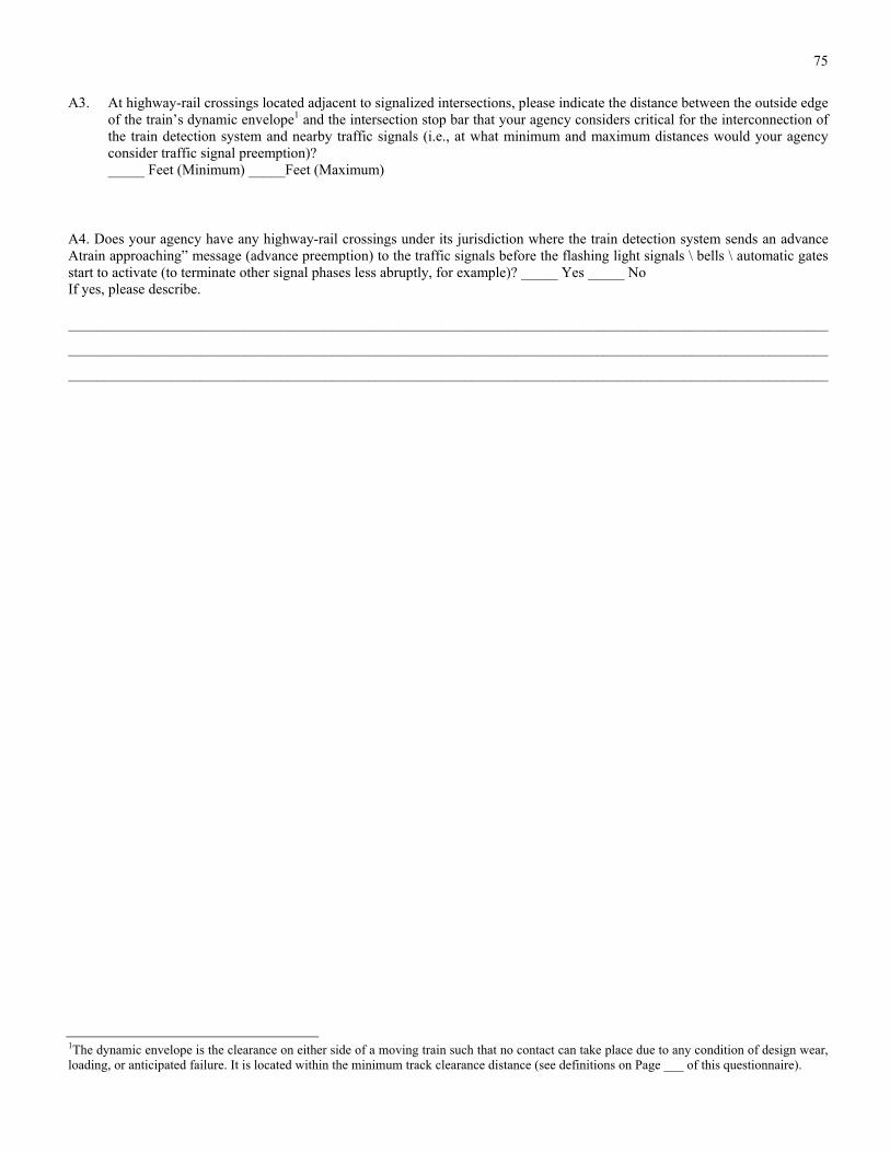
75
A3. At highway-rail crossings located adjacent to signalized intersections, please indicate the distance between the outside edge of the train’s dynamic envelope1 and the intersection stop bar that your agency considers critical for the interconnection of the train detection system and nearby traffic signals (i.e., at what minimum and maximum distances would your agency consider traffic signal preemption)? _____ Feet (Minimum) _____Feet (Maximum)
A4. Does your agency have any highway-rail crossings under its jurisdiction where the train detection system sends an advance Atrain approaching” message (advance preemption) to the traffic signals before the flashing light signals \ bells \ automatic gates start to activate (to terminate other signal phases less abruptly, for example)? _____ Yes _____ No If yes, please describe.
________________________________________________________________________________________________________
________________________________________________________________________________________________________
________________________________________________________________________________________________________
1The dynamic envelope is the clearance on either side of a moving train such that no contact can take place due to any condition of design wear, loading, or anticipated failure. It is located within the minimum track clearance distance (see definitions on Page ___ of this questionnaire).

76
A5. For highway-rail crossings under your agency’s jurisdiction that are located near signalized intersections, please indicate the types of train detection systems.
TRAIN DETECTION SYSTEM NUMBER OF HIGHWAY-RAIL CROSSINGS
(CURRENT INSTALLATIONS)
WOULD USE TODAY OR IN THE FUTURE?
(YES/NO)
Island-Only Circuits
3 - DC or AC Track Circuits
3 - AC / DC Track Circuits
Audio Frequency Overlay (AFO) Circuits
Motion Sensor Systems
Constant Warning Time Systems (Grade Crossing Predictors)
Off-track Detection Systems
A6. Per your agency’s policies / practices, please describe the sequence of events (in seconds) of both the highway-rail crossing warning systems and the nearby traffic signals, from the time the train detection system sends a “train approaching” mes-sage to the highway-rail crossing warning systems and the traffic signal controller to the time the train arrives in the high-way-rail crossing2. Please provide a sketch or more detail if appropriate.
__________________________________________________________________________________________________
__________________________________________________________________________________________________
__________________________________________________________________________________________________
A7. Are train operators / engineers required to sound a horn • at every highway-rail crossing under your agency’s jurisdiction? _____
OR
• only at highway-rail crossings where there is a potential conflict? _____
A8. For those highway-rail crossings located near highway intersections controlled by traffic signals, does your agency use an event recorder • for the grade crossing warning devices? _____ Yes _____No • for the interconnection of the train detection system and the traffic signals? _____ Yes _____No • for the complete grade crossing warning / traffic signal system? _____ Yes _____No
2Example: flashing light signals for 3 seconds then the automatic gates begin to descend. When the automatic gates reach a 45 degree angle (about 4 seconds after the gates begin to descend), the nearby signalized intersection provides a green signal indication to vehicles that may be queued on the tracks. The automatic gates are in the horizontal position about 4 seconds later and the traffic signal stays green for 4 more sec-onds and then changes to yellow and red. Ten seconds later, the train should arrive at the highway-rail crossing for a total of 25 seconds.

77
A9. How does your agency identify and manage malfunctions in • highway-rail crossing warning systems?
__________________________________________________________________________________________________
__________________________________________________________________________________________________
__________________________________________________________________________________________________
• the interconnection of the train detection systems and nearby traffic signals?
__________________________________________________________________________________________________
__________________________________________________________________________________________________
__________________________________________________________________________________________________
A10. Does your agency have highway-rail crossings under its jurisdiction that are monitored by intrusion detection equipment? _____ Yes _____ No If yes, please describe the system and what happens if an intrusion is detected.
__________________________________________________________________________________________________
__________________________________________________________________________________________________
A11. Does your agency maintain a highway-rail crossing inventory? _____ Yes _____ No If yes, please list and describe briefly any additional items tracked in your inventory that are not standard to the United States Department of Transportation (U.S. DOT) - Association of American Railroads (AAR) inventory requirements (see Figure A1 on the following page for the U.S. DOT - AAR Crossing Inventory Form). If your agency’s highway-rail crossing inventory is generally different than the U.S. DOT - AAR inventory, please provide a sample page.
__________________________________________________________________________________________________
__________________________________________________________________________________________________
__________________________________________________________________________________________________
A12. Does your agency have criteria for selecting highway-rail crossing warning devices and preemption practices depending on the operating characteristics of the crossing trains (e.g., train speed, length, frequency, type, etc.)? _______ Yes _______ No If yes, please provide a brief description below and a copy of the criteria and related highway-rail crossing warning devices.
__________________________________________________________________________________________________
__________________________________________________________________________________________________
__________________________________________________________________________________________________

78

79
A13. Does your agency have guidelines or standards for implementing pedestrian automatic gates3? _______ Yes _______ No If yes, please describe and/or provide a copy of the guidelines / standards.
________________________________________________________________________________________________________
________________________________________________________________________________________________________
________________________________________________________________________________________________________
A14. Does your agency have any special design guidelines or practices that provide stopped vehicles with an escape route off highway-rail crossings (out of the track clearance distance) should a train approach? _______ Yes _______ No If yes, please describe and provide a copy.
________________________________________________________________________________________________________
________________________________________________________________________________________________________
________________________________________________________________________________________________________
THANK YOU AGAIN FOR TAKING TIME OUT OF YOUR BUSY SCHEDULE TO PROVIDE THIS INFORMATION FOR THE SYNTHESIS REPORT
3Pedestrian automatic gates are the same as standard automatic gates for vehicles except that the gate arm is shorter. The gate arm blocks the pedestrian path (e.g., sidewalk) when a train is approaching the crossing. Pedestrian automatic gates are usually provided in all four quadrants of the crossing (blocking both directions of pedestrian travel on both sides of the crossing roadway). Alternatively, the automatic gates that block vehicle movements can be located behind the sidewalk (instead of just behind the curb) to block pedestrians from crossing the tracks in two of the four highway-rail crossing quadrants.

80
B. HIGHWAY TRAFFIC CONTROL SYSTEMS
If different from Part A, please provide the name of the person completing this section of the questionnaire, or who may be contacted to obtain follow-up information:
Name _____________________________________________________________________________________________ Title _____________________________________________________________________________________________ Agency _____________________________________________________________________________________________ Address _____________________________________________________________________________________________ Telephone (_______)_________________ Fax (_______)_________________ email_________________________________
Please respond to ALL of the following questions in this section FOR EACH MAJOR RAIL LINE under you agency’s juris-diction (including various freight railroads, commuter railroads, and light rail transit systems). If you are unsure of the answer to a particular question or do not understand a question, please state so. If additional space is needed to answer any of the following questions, please use the back of this questionnaire or attach other sheets of paper. If available, please enclose with this survey form any additional materials such as plans, specifications, reports, etc. that you feel may be of value to this synthesis effort.
Please mail the completed questionnaire by March 28, 1997, to:
Mr. Hans W. Korve, P.E. Korve Engineering, Inc.
155 Grand Avenue, Suite 400 Oakland, California 94612
Tel: (510) 763-2929 Fax: (510) 451-4549
THANK YOU FOR YOUR ASSISTANCE.
B1. Please indicate whether your agency uses any of the following signs or pavement markings (striping) at crossings located near intersections controlled by traffic signals?
SIGNING & STRIPING YES
Blank-Out or Train Activated, Internally Illuminated Signs
NO RIGHT TURN
NO LEFT TURN
NO TURN ON RED
Signs
DO NOT STOP ON TRACKS
NO TURN ON RED
Striping
Cross Hatch Lines

81
B2. Other than the Manual on Uniform Traffic Control Devices (MUTCD), does your agency have a written policy or guide-lines on signing and striping (pavement markings) for highway-rail crossings? _______ Yes _______ No If yes, please provide the name and a copy of the title page and table of contents.
__________________________________________________________________________________________________
__________________________________________________________________________________________________
__________________________________________________________________________________________________
B3. Does your agency use or maintain traffic signal installation warrants / guidelines that specifically consider the presence of nearby highway-rail crossings? _______ Yes _______ No For example, some states maintain their own expanded version of the Manual on Uniform Traffic Control Devices (e.g., the California Department of Transportation’s Traffic Manual), modified for local practices and policies. Please describe and/or provide a copy of the relevant warrants / guidelines.
__________________________________________________________________________________________________
__________________________________________________________________________________________________
__________________________________________________________________________________________________
B4. Please indicate what types of traffic signal equipment (traffic signal controllers) are interconnected with train detection systems. Please specify controller types (e.g., electro-mechanical, NEMA, Type 170, etc.).
TRAFFIC SIGNAL CONTROLLER TYPE
TRAIN DETECTION INTERFACE (YES/NO)
DESCRIPTION
Electro-Mechanical
NEMA(a)
Type 170
Other __________
Other __________
(a) National Electrical Manufacturers Association
B5. At signalized intersections with solid state traffic signal controllers that are interconnected with train detection systems, please:
1) State the type of traffic signal control software.
__________________________________________________________________________________________________
2) Describe the flexibility (to the agency, to the traffic demand, etc.) that this software offers for the preemption and recov-ery of the traffic signal.
__________________________________________________________________________________________________
__________________________________________________________________________________________________
__________________________________________________________________________________________________

82
B6. In the following table, please indicate the types of control/warning (e.g., protected signal phases, train-activated turn prohi-bition signs, flashing light signals, etc.) that are typically provided for motorists turning left or right from a roadway that parallels the rail alignment across the highway-rail crossing (perpendicular crossing roadway). Also indicate any improve-ments to the existing devices that your agency would like to consider to better control motorists turning into the rail align-ment.
VEHICLE TURN CONTROL/WARNING
DEVICES
TYPICALLY PROVIDED (YES/NO)
DESCRIPTION POTENTIAL IMPROVEMENTS
Protected Signal Phase
Passive Turn Prohibition Signs
Train Activated Turn Prohibi-tion Signs
Flashing Light Signals
Automatic Gate
Other __________
Other __________
B7. Please indicate in the following table the traffic signal indications that are displayed once the train detection system sends the preemption call to the traffic signals in order to clear any motorists who are queued on the tracks?
TRAFFIC SIGNAL INDICATION TO CLEAR VEHICLES OFF THE TRACKS
TYPICALLY DISPLAYED (YES/NO)
DESCRIPTION
Flashing Red Ball
Flashing Yellow Ball
Solid Green Ball
Solid Green Ball Plus Green Arrow
Other __________
Other __________
B8. Please indicate in the following table the traffic signal indications provided after the traffic signals have displayed indica-tions to clear any vehicles off of the tracks (i.e., during the remainder of the preemption)? For example, is traffic that paral-lels the rail alignment allowed to proceed on green ball indications? Do all traffic signals (i.e., the traffic signals for all

83
roadway approaches) switch to flashing red indications (including any protected turning movements)? Do all traffic signals provide solid red ball indications?
TRAFFIC SIGNAL
INDICATION DURING
PREEMPTION
PARALLEL (NON-RAIL CROSSING)
TRAFFIC (YES/NO)
TURNING TRAFFIC (INTO RAIL CROSSING)
PERPENDICULAR (RAIL CROSSING)
TRAFFIC (YES/NO)
OTHER TRAFFIC (YES/NO)
LEFT (YES/NO)
RIGHT (YES/NO)
Flashing Red Ball
Flashing Yellow Ball
Solid Red Ball
Solid Green Ball
Red Arrow
Green Arrow
Other __________
Other __________
__________________________________________________________________________________________________
__________________________________________________________________________________________________
__________________________________________________________________________________________________
B9. Does your agency have highway-rail crossings under its jurisdiction that use standard traffic signals indications (red, yel-low, green ball indications) instead of red flashing light signals? _______ Yes _______ No If yes, please briefly describe the types of trains and typical train speeds through the crossing.
__________________________________________________________________________________________________
__________________________________________________________________________________________________
__________________________________________________________________________________________________
B10. Does your agency have any warrants guidelines for the possible replacement of STOP signs with traffic signals at intersec-tions located near highway-rail crossings? _______ Yes _______ No For example, if vehicles are queuing from the nearby STOP controlled intersection back towards the highway-rail crossing, does your agency have any guidelines for when an interconnected signal should be installed in lieu of the STOP sign? Please state the guidelines or provide a copy.
__________________________________________________________________________________________________
__________________________________________________________________________________________________
__________________________________________________________________________________________________

84
B11. When a traffic signal is preempted due to an approaching train at a nearby highway-rail crossing, how does your agency consider pedestrian clearance timing across the roadway approaches to the signalized intersection? For example, are the pedestrian clearance phases terminated early (before the pedestrian could actually finish crossing the roadway) to allow vehicles to clear the track area with green traffic signal indications? _______ Yes _______ No Please describe and/or pro-vide signal timing plans showing pedestrian phasing during and after preemption.
__________________________________________________________________________________________________
__________________________________________________________________________________________________
__________________________________________________________________________________________________
B12. At highway-rail crossings where the train detection system is interconnected with nearby traffic signals (with pedestrian signals), please specify the indications that the pedestrian signals display during a preemption.
PEDESTRIAN SIGNAL INDICATION TYPICALLY DISPLAYED AT THE
INTERSECTION DURING PREEMPTION
PEDESTRIANS CROSSING THE
PARALLEL ROADWAY (YES/NO)
PEDESTRIANS CROSSING THE
PERPENDICULAR ROADWAY (YES/NO)
Walk (Person)
Solid Don’t Walk (Hand)
Flashing Don’t Walk (Hand)
Blank (No Indication)
Other _____________________
Other _____________________
__________________________________________________________________________________________________
__________________________________________________________________________________________________
__________________________________________________________________________________________________
B13. At intersections with traffic signals and pedestrian signals that are interconnected with a train detection system, does your agency terminate the pedestrian phases early to clear vehicles off the tracks? _______ Yes _______ No
If yes, does your agency provide these pedestrians with any sort of warning sign or message saying that their crossing sig-nal may be terminated due to an approaching train? _______ Yes _______ No If yes, please describe the warning type and / or message.
__________________________________________________________________________________________________
__________________________________________________________________________________________________
__________________________________________________________________________________________________

85
B14. At highway-rail crossings where the train detection system is interconnected with highway traffic signals and where there are special signal timing or preemption sequences, does your agency use any type of computer simulation model (e.g., TRAF-NETSIM) to analyze traffic operations, including potential vehicle queues extending back from the intersection to-wards the highway-rail crossing? _____ Yes _____ No If yes, please describe.
__________________________________________________________________________________________________
__________________________________________________________________________________________________
__________________________________________________________________________________________________
B15. Does your agency have highway-rail crossings under its jurisdiction that use queue “cutter” traffic signals4? _____ Yes _____ No If yes, please identify the location and describe the queue “cutter” traffic signal operations.
__________________________________________________________________________________________________
__________________________________________________________________________________________________
__________________________________________________________________________________________________
B16. Does your agency coordinate interconnection efforts with other involved parties / agencies, including responsibilities for maintenance and notifying other parties / agencies of changes in the status of highway-rail crossing warning system activa-tion or traffic signal timing? _____ Yes _____ No
Please indicate the type of inspection your agency conducts and what is inspected: • separate inspections (i.e., with no other agencies) of _______________________________________________________ • joint inspections with _____________________ (list agencies) of ____________________________________________
Please indicate the frequency your agency conducts these inspections. • separate inspections: _____________ per ____________ (time period) • joint inspections: _____________ per ____________ (time period)
THANK YOU AGAIN FOR TAKING TIME OUT OF YOUR BUSY SCHEDULE TO PROVIDE THIS INFORMATION FOR THE SYNTHESIS REPORT
4 Queue “cutter” traffic signals are standard traffic signals located on the near side of a highway-rail crossing that function to prevent queues from building across the track area, whether or not a train is approaching the highway-rail crossing. For example, the traffic signal on the near side of the highway-rail crossing would change to red several seconds before the traffic signal on the far side of the highway-rail crossing, clear-ing the track area on every cycle. Or, if a vehicle queue is detected building towards the far side of a highway-rail crossing (using loop detectors or other means) from a nearby signalized intersection, the near side traffic signals would change to red, not allowing the queue to build back over the tracks, whether or not a train is approaching the highway-rail crossing.

86
APPENDIX B
Questionnaire for Railroad Companies/Agencies
As part of the National Cooperative Highway Research Project 20-5, Synthesis Project 28-12, we would appreciate it if you would take time out of your busy schedule to complete the following survey on HIGHWAY - RAIL CROSSING WARNING / CONTROL SYSTEMS (page ___).
BACKGROUND
At 7:10 AM on October 25, 1995, a school bus transporting 35 high school students stopped at a highway-rail crossing in Fox River Grove, Illinois, and was struck by a commuter train. Seven students died as a result of this accident. Following this bus/train collision, the U. S. Department of Transportation (DOT) formed the Grade Crossing Safety Task Force to investigate and assess the decision-making and coordination processes, as well as the safety aspects, affecting the planning, design, construction, main-tenance, and operation of highway-rail crossings. The final report of the Task Force, “Accidents That Shouldn’t Happen,” dated March 1, 1996, addresses five topic areas: interconnected highway traffic signals, critical storage distance for vehicles between rail lines and highway intersections, high-profile highway-rail crossings, light rail transit highway-rail crossings, and the inclusion of highway-rail crossing information in the permit process for special vehicles.
One major finding of the Task Force is that there are no firm guidelines on when the interconnection of highway-rail crossing warning devices (specifically, train detection systems) and downstream traffic signals should take place. The Manual on Uniform Traffic Control Devices for Streets and Highways (MUTCD) states that interconnection should be provided when the distance is 200 feet or less, except under unusual circumstances. However, this 200-foot guideline could be improved to consider possible vehicle queue lengths extending from nearby signalized intersections. The MUTCD and other publications also lack comprehen-sive guidance on traffic signal preemption timing (including traffic signal recovery from preemption), pedestrian needs, when to install traffic signals near highway-rail crossings, and turn prohibitions across the tracks from roadways that parallel the rail alignment.
SAMPLE SCENARIO AND DEFINITIONS
The figure below (SEE FIGURE 1 IN CHAPTER ONE) presents a sample highway-rail crossing located near a highway inter-section controlled by traffic signals. The Minimum Track Clearance Distance and the Clear Storage Distance are defined as fol-lows:
1. Minimum Track Clearance Distance: The distance along a highway at one or more tracks, measured either from the Rail Stop Line, warning device, or 12 feet perpendicular to the track centerline, to 6 feet beyond the track(s), measured perpendicular to the far rail, along the centerline or right edge line of the highway, as appropriate, to obtain the longest distance.
2. Clear Storage Distance: The distance available for vehicle storage measured between 6 feet from the rail nearest the inter-section to the intersection Stop Bar or the normal stopping point on the highway. At skewed crossings and intersections, the six foot distance shall be measured perpendicular to the nearest rail either along the centerline or right edge line of the highway, as appropriate, to obtain the shortest distance.
Other terms used throughout this questionnaire:
Preemption: The transfer of normal operation of traffic signals to a special control mode.
Interconnection: The electrical connection between the railroad active warning system and the traffic signal controller assembly for the purpose of preemption.
Queue Clearance Time: The time required for a vehicle stopped in a queue of vehicles just beyond the tracks to start up and move through the track clearance distance.
Advance Preemption: Notification of an approaching train that is forwarded to the highway traffic controller unit or assembly by rail equipment some time prior to activating the railroad active warning devices.
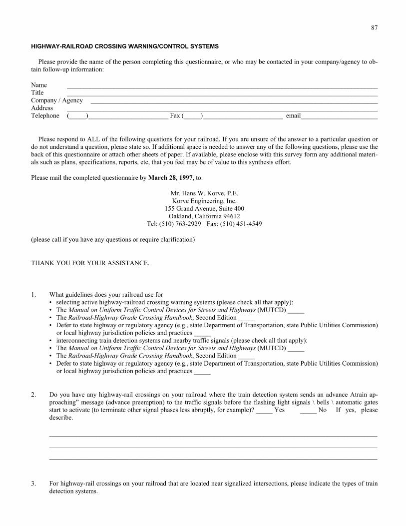
87
HIGHWAY-RAILROAD CROSSING WARNING/CONTROL SYSTEMS
Please provide the name of the person completing this questionnaire, or who may be contacted in your company/agency to ob-tain follow-up information:
Name _____________________________________________________________________________________________ Title _____________________________________________________________________________________________ Company / Agency ______________________________________________________________________________________ Address _____________________________________________________________________________________________ Telephone (_____)________________________ Fax (_____)________________________ email_______________________
Please respond to ALL of the following questions for your railroad. If you are unsure of the answer to a particular question or do not understand a question, please state so. If additional space is needed to answer any of the following questions, please use the back of this questionnaire or attach other sheets of paper. If available, please enclose with this survey form any additional materi-als such as plans, specifications, reports, etc, that you feel may be of value to this synthesis effort.
Please mail the completed questionnaire by March 28, 1997, to:
Mr. Hans W. Korve, P.E. Korve Engineering, Inc.
155 Grand Avenue, Suite 400 Oakland, California 94612
Tel: (510) 763-2929 Fax: (510) 451-4549
(please call if you have any questions or require clarification)
THANK YOU FOR YOUR ASSISTANCE.
1. What guidelines does your railroad use for • selecting active highway-railroad crossing warning systems (please check all that apply): • The Manual on Uniform Traffic Control Devices for Streets and Highways (MUTCD) _____ • The Railroad-Highway Grade Crossing Handbook, Second Edition _____ • Defer to state highway or regulatory agency (e.g., state Department of Transportation, state Public Utilities Commission)
or local highway jurisdiction policies and practices _____ • interconnecting train detection systems and nearby traffic signals (please check all that apply): • The Manual on Uniform Traffic Control Devices for Streets and Highways (MUTCD) _____ • The Railroad-Highway Grade Crossing Handbook, Second Edition _____ • Defer to state highway or regulatory agency (e.g., state Department of Transportation, state Public Utilities Commission)
or local highway jurisdiction policies and practices _____
2. Do you have any highway-rail crossings on your railroad where the train detection system sends an advance Atrain ap-proaching” message (advance preemption) to the traffic signals before the flashing light signals \ bells \ automatic gates start to activate (to terminate other signal phases less abruptly, for example)? _____ Yes _____ No If yes, please describe.
__________________________________________________________________________________________________
__________________________________________________________________________________________________
__________________________________________________________________________________________________
3. For highway-rail crossings on your railroad that are located near signalized intersections, please indicate the types of train detection systems.

88
TRAIN DETECTION SYSTEM NUMBER OF HIGHWAY-RAIL
CROSSINGS (CURRENT INSTALLATIONS)
WOULD USE TODAY OR IN THE FUTURE?
(YES/NO)
Island-Only Circuits
DC or AC Track Circuits
AC / DC Track Circuits
Audio Frequency Overlay (AFO) Circuits
Motion Sensor Systems
Constant Warning Time Systems (Grade Crossing Predictors)
Off-track Detection Systems _______________
Other _______________
Other _______________
4. For highway-rail crossings on your railroad, please describe the sequence of events (in seconds) of both the highway-rail crossing warning systems and the nearby traffic signals, from the time the train detection system sends a “train approach-ing” message to the highway-rail crossing warning systems and the traffic signal controller to the time the train arrives in the highway-rail crossing5. Please provide a sketch or more detail if appropriate.
__________________________________________________________________________________________________
__________________________________________________________________________________________________
__________________________________________________________________________________________________
5. Are train operators / engineers required to sound a horn • at every public highway-rail crossing (crossing roadways used by the general public)? _____ Yes _____ No • at every private highway-rail crossing (crossing on private property)? _____ Yes _____ No If no to either of the above, please describe:
__________________________________________________________________________________________________
__________________________________________________________________________________________________
__________________________________________________________________________________________________
5 Example: flashing light signals for 3 seconds then the automatic gates begin to descend. When the automatic gates reach a 45 degree angle (about 4 seconds after the gates begin to descend), the nearby signalized intersection provides a green signal indication to vehicles that may be queued on the tracks. The automatic gates are in the horizontal position about 4 seconds later and the traffic signal stays green for 4 more sec-onds and then changes to yellow and red. Ten seconds later, the train should arrive at the highway-rail crossing for a total of 25 seconds.

89
6. For those highway-rail crossings located near highway intersections controlled by traffic signals, does your railroad use an event recorder • for the grade crossing warning devices? _____ Yes _____ No • for the interconnection of the train detection system and the traffic signals? _____ Yes _____ No • for the complete grade crossing warning / traffic signal system? _____ Yes _____ No
__________________________________________________________________________________________________
__________________________________________________________________________________________________
__________________________________________________________________________________________________
7. How does your railroad identify and manage malfunctions in • highway-rail crossing warning systems?
__________________________________________________________________________________________________
__________________________________________________________________________________________________
__________________________________________________________________________________________________
• the interconnection of the train detection systems and nearby traffic signals?
__________________________________________________________________________________________________
__________________________________________________________________________________________________
__________________________________________________________________________________________________
8. Does your railroad use highway-rail crossings that are monitored by intrusion detection equipment? _____ Yes _____ No If yes, please describe the system and what happens if an intrusion is detected.
__________________________________________________________________________________________________
__________________________________________________________________________________________________
__________________________________________________________________________________________________
9. Does your railroad maintain a highway-rail crossing inventory? _____ Yes _____ No If yes, please list and describe briefly any additional items tracked in your inventory that are not standard to the United States Department of Transportation (U.S. DOT) - Association of American Railroads (AAR) inventory requirements (see Figure A1 on the following page for the U.S. DOT - AAR Crossing Inventory Form). If your railroad’s highway-rail crossing inventory is generally different than the U.S. DOT - AAR inventory, please provide a sample page.
__________________________________________________________________________________________________
__________________________________________________________________________________________________
__________________________________________________________________________________________________
THANK YOU AGAIN FOR TAKING TIME OUT OF YOUR BUSY SCHEDULE TO PROVIDE THIS INFORMATION FOR THE SYNTHESIS REPORT

90
APPENDIX C
Responding Transportation Agencies and Railroad Operators
State Departments of Transportation
Arizona Louisiana North Dakota Arkansas Maryland Ohio California Massachusetts Oregon Connecticut Michigan Pennsylvania Delaware Minnesota Rhode Island Florida Mississippi South Carolina Georgia Missouri Virginia Hawaii Nebraska Washington State Idaho Nevada West Virginia Illinois New Jersey Wisconsin Iowa New York Wyoming Kentucky North Carolina
Railroads
AMTRAK Burlington Northern Sante Fe (BNSF) Consolidated Rail Corporation (CONRAIL) CSX Transportation Gulf and Ohio Railways Kansas City Southern Railway Long Island Railroad* METRA (Northeast Illinois Regional Commuter Railroad
Corporation)* Massachusetts Bay Transportation Authority Commuter Rail* Metro-North Railroad (New York)* Metrolink (Southern California Regional Rail Authority)* NJ Transit Rail (New Jersey)* Norfolk Southern Tri-County Commuter Rail Authority (Florida)* Virginia Railway Express*
* Indicates commuter railroad agency
Light Rail Transit
Baltimore LRT System (Mass Transit Administration) Boston LRT System (Massachusetts Bay Transportation Authority) Calgary LRT System (Calgary Transit) Denver LRT System (Regional Transportation District) Edmonton LRT System (Edmonton Transit System) Pittsburgh LRT System (Port Authority of Allegheny
County) Saint Louis LRT System (Bi-State Development Agency) San Diego LRT System (San Diego Trolley, Inc.)

THE TRANSPORTATION RESEARCH BOARD is a unit of the National Research Council, a private, nonprofit institution that provides independent advice on scientific and technical issues under a congressional charter. The Research Council is the principal operating arm of the National Academy of Sciences and the National Academy of Engineering.
The mission of the Transportation Research Board is to promote innovation and progress in transportation by stimulating and conducting research, facilitating the dissemination of information, and encouraging the implementation of research findings. The Board’s varied activities annually draw on approximately 4,000 engineers, scientists, and other transportation researchers and practitioners from the public and private sectors and academia, all of whom contribute their expertise in the public interest. The program is supported by state transportation departments, federal agencies including the component administrations of the U.S. Department of Transportation, and other organizations and individuals interested in the development of transportation.
The National Academy of Sciences is a nonprofit, self-perpetuating society of distinguished scholars engaged in scientific and engineering research, dedicated to the furtherance of science and technology and to their use for the general welfare. Upon the authority of the charter granted to it by the Congress in 1863, the Academy has a mandate that requires it to advise the federal government on scientific and technical matters. Dr. Bruce Alberts is president of the National Academy of Sciences.
The National Academy of Engineering was established in 1964, under the charter of the National Academy of Sciences, as a parallel organization of outstanding engineers. It is autonomous in its administration and in the selection of its members, sharing with the National Academy of Sciences the responsibility for advising the federal government. The National Academy of Engineering also sponsors engineering programs aimed at meeting national needs, encouraging education and research, and recognizes the superior achievements of engineers. Dr. William A. Wulf is president of the National Academy of Engineering.
The Institute of Medicine was established in 1970 by the National Academy of Sciences to secure the services of eminent members of appropriate professions in the examination of policy matters pertaining to the health of the public. The Institute acts under the responsibility given to the National Academy of Sciences, by its congressional charter to be an adviser to the federal government and, upon its own initiative, to identify issues of medical care, research, and education. Dr. Kenneth I. Shine is president of the Institute of Medicine.
The National Research Council was organized by the National Academy of Sciences in 1916 to associate the broad community of science and technology with the Academy’s purposes of furthering knowledge and advising the federal government. Functioning in accordance with general policies determined by the Academy, the Council has become the principal operating agency of both the National Academy of Sciences and the National Academy of Engineering in providing services to the government, the public, and the scientific and engineering communities. The Council is administered jointly by both Academies and the Institute of Medicine. Dr. Bruce Alberts and Dr. William A. Wulf are chairman and vice chairman, respectively, of the National Research Council.