transportation research record 1290 urban...
TRANSCRIPT

28 TRANSPORTATION RESEARCH RECORD 1290
Urban Second Level Bridges Built with Precast Segmental Construction
JOHN A. CORVEN
Transportation facilities In most major urban areas in the United States are operating far beyond their design capacities. Extensive rehabilitation, renovation and new construction is required if we hope to meet our future needs. The challenge facing the engineering community Is to develop techniques to provide increased capacity, Improved safety, at reasonable cost, while minimizing the impact on the operation of the current facility. Second level bridges built with precast segmental construction provide one important solution to this challenge.
Precast segmental second level bridges can offer an effective solution to relieving traffic congestion of many of our urban areas. Additional traffic lanes are added on the second level, typically for through traffic leaving the at-grade facility to operate within its design capacity. The new structures are designed in accordance with current geometric criteria (such as site and stopping distances and shoulder widths). The existing facility can also be upgraded to comply with current geometric standards. The construction· costs of the elevated structures have proven to be very competitive, especially when comparing the high expense, and near impossible task, of securing the surrounding right-of-way. Finally the construction techniques developed of building from above and the elimination of underlying falsework allow the current facility to operate with minimal disruption during the construction of the elevated bridges.
The recent design and construction of three major urban viaducts has developed this special aspect of segmental construction, the construction of elevated urban bridges. Criteria for these bridges are not necessarily the same as other bridge structures. These criteria include aesthetic considerations, geometry layout of roadways to minimize impact on underlying traffic and reduce construction costs, innovative drainage techniques, and special substructure elements designed to meet the complexity of crossing over underlying roadways. To describe these criteria three recent projects are discussed. These are:
• 1-110, Blloxl, Mississippi - $40 million urban structures built through residential area, and over 4-lane U.S. 90 highway, while maintaining traffic. Segmental portion of the first contract contains 316,600 square feet, with 300,000 square feet in Contract II. The structures were opened to traffic February 19, 1988. •San Antonio "Y," Texas Pro)ects IA, 118 and lllA&B of 1-10 & 1-35 - $65 million urban structures built in limited right-of-way over streets and railroads. These projects are
Figg Engineernig Group, 424 North Calhoun, Tallahassee, Fl 32301
the first phase of reconstruction of the downtown urban freeways of San Antonio, which will ultimately consist of a new 10-lane expressway with provision for HOV lanes. Over 1.25 million square feet of elevated roadway deck. • U.S. 183 Elevated Viaduct Project In Austin, Texas -The project has two parallel structures approximately two miles each providing a six-lane freeway and directional ramps to IH-35. The bridge deck area is approximately 1.25 million square feet with an estimated cost of $60 million. Construction is anticipated to begin in May 1991.
PROJECT 1: BILOXI 1-110 VIADUCT
An elevated viaduct constructed within minimal clearance and almost zero right-of-way limits solved a dilemma for Biloxi, Mississippi: How to expand interstate systems in developed urban areas where highways must wrap around existing structures; minimize the impact to the environment when urban structures are built; maintain the integrity of established neighborhoods; utilize construction systems that don't interfere with day-to-day traffic flow; and, provide an aesthetically pleasing road and bridge system for a city.
Highway Department officials had not completed the Biloxi lnterstate-110 connector between lnterstate-10, a vital route, with U.S. Highway 90, which follows the coast of the Gulf of Mexico. The connecter stopped a mile before reaching U.S. 90. The missing link had to traverse an neighborhood and then a business community that was immediately adjacent to the Gulf of Mexico. The existing buildings made it almost impossible to acquire right-of-way land to build exit ramps. Additionally, highway department officials did not want to disrupt the community or stop traffic on what is a major tourist route.
An elevated viaduct with exit and entrance ramps that circle out into the Gulf of Mexico at its Southern end solved the problem. Concrete segmental technology was an excellent solution for zero right-of-way construction.
Project Description
The Biloxi lnterstate-110 Viaduct is a four-lane elevated highway consisting of 5,332' of mainline structure and 4,424' of ramps, for a total precast concrete segmental bridge deck area of 616,600 square feet. The bridge foundations are cast-in-place concrete columns supported on 95,000' of precast, prestressed concrete piles. Two of the five ramps reach across a U.S. Highway 90, on 600' and 650' radii curves using the cantilever erection method.
Twin concrete box girders, each made of 40' wide precast segments, comprise much of the mainline structure.
Carven
The ramps and transition areas feature 30' wide precast segments. All of the segments are 7' deep, with typical segments 1 O' in length. In ramp transition areas, as many as four adjacent box girders, joined with cast-in-place reinforced longitudinal closure strips, make up the bridge deck.
Casting of the prestressed piles and 2, 164 segments required for the bridge was done at a casting yard 35 miles from the project site. The precast elements were then trucked to the project for incorporation into the structure.
Significant Bridge Features
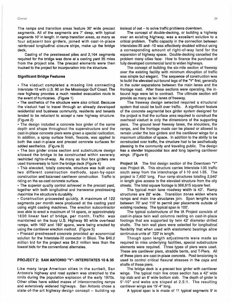
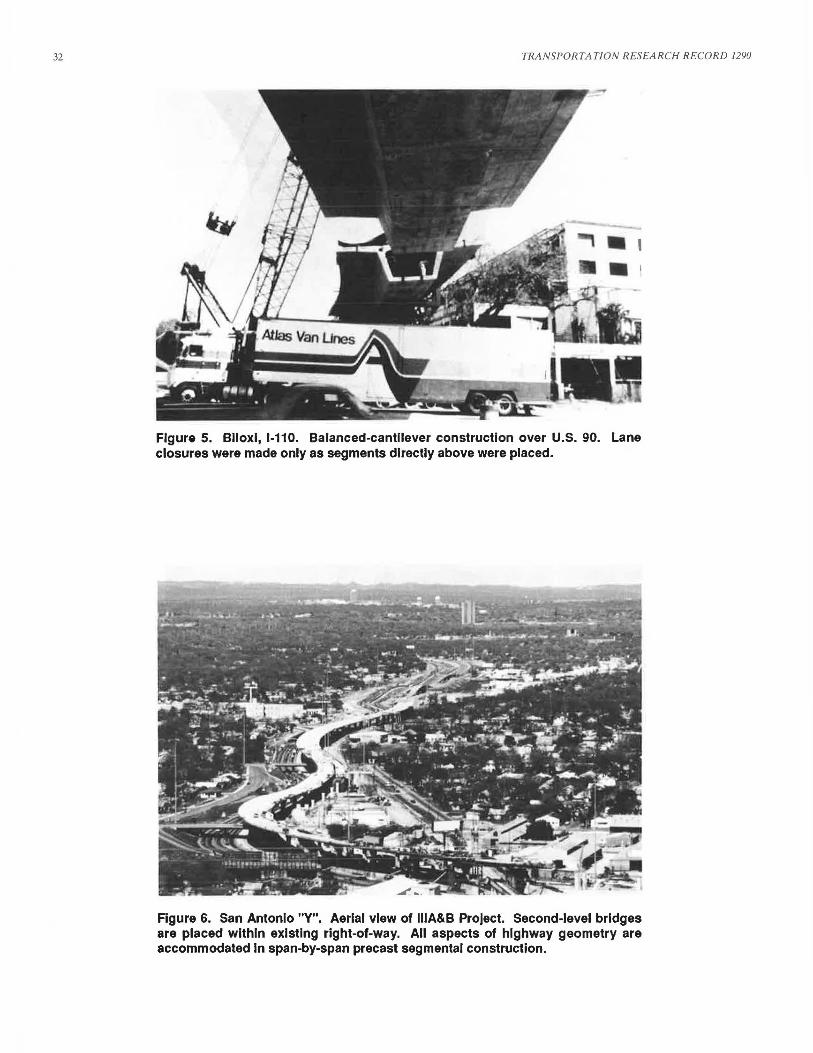
• The viaduct completed a missing link connecting lnterstate-10 with U.S. 90 on the Mississippi Gulf Coast. The new highway provides a much needed evacuation route in the event of hurricanes. (Figure 1) • The aesthetics of the structure were also critical. Because the viaduct had to travel through an already developed residential and business community, residents and tenants tended to be reluctant to accept a new highway structure. (Figure 2) • The design included a concrete box girder of the same depth and shape throughout the superstructure and the cast-in-place concrete piers were given a spacial rustication. In addition, a spray surface finish, Texcote, was applied to both the cast-in-place and precast concrete surfaces for added aesthetics. (Figure 3) • The box girder cross section and substructure design allowed the bridge to be constructed within severely restricted rights-of-way. As many as four box girders are used transversely to form the bridge deck (Figure 4) • This elevated, totally concrete, structure was built using two different construction methods, span-by-span construction and balanced cantilever construction. Traffic is riding on the as-cast concrete surface. • The superior quality control achieved in the precast yard, together with both longitudinal and transverse prestressing maximize the structure's durability. • Construction proceeded quickly. A maximum of 122 segments per month were produced at the casting yard using eight casting machines. The erection subcontractor was able to erect a maximum of 14 spans, or approximately 1600 linear feet of bridge, per month. Traffic was maintained on the busy U.S. Highway 90 while overhead ramps, with 160' and 180' spans, were being erected by using the cantilever erection method. (Figure 5) • Precast prestressed concrete provided an economical solution for the lnterstate-110 connector in Biloxi. The $40.2 million bid for the project was $4.2 million less than the lowest bids for the conventional alternates.
PROJECT 2: SAN ANTONIO "Y"- INTERSTATES 10 & 35
Like many large American cities in the sunbelt, San Antonio's highway and road system was stretched to the limits during the population explosion of the early 1970s. Other cities have added mazes of interconnecting ramps and extensively widened highways. San Antonio chose a state-of-the-art highway-design concept -- building up
29
instead of out -- to solve traffic problems downtown. The concept of double-decking, or building a highway
over an existing highway, was a excellent solution to a critical problem. Traffic capacity in the connection between lnterstates-35 and -10 was effectively doubled without using a corresponding amount of right -of-way land for the expansion of highway space. Double-decking cancelled the problem many cities face: How to finance the purchase of fully developed commercial land to widen highways.
The concept of building the six-mile section of freeway over the existing facility with minimum disruption of traffic was simple but elegant. The sequence of construction was to build the elevated out-bound legs of the "Y" first, generally in the outer separations between the main lanes and the frontage road. After these sections were operating, the inbound legs were let to contract. The ultimate section will provide as many as ten lanes of freeway.
The freeway design selected required a structural system that could be built over traffic. A significant feature of the concrete segmental box girder system designed for the project is that the surface area required to construct the overhead viaduct is only the dimensions of the supporting piers. The ground level freeway lanes, the shoulders, the ramps, and the frontage roads can be placed or allowed to remain under the box girders and the cantilever wings for a maximum utilization of space. In addition to the ability to be constructed over traffic, the structure had to be aesthetically pleasing to the community and traveling public. The design has a slender trapezoidal box and long tapering cantilever wings. (Figure 6)
Project IA The first design section of the Downtown "Y" was Project IA. This structure carries Interstate 1-35 traffic south away from the interchange of 1-10 and 1-35. The project is 7,450' long. Four ramp structures totalling 2,540' in length give access to the elevated structure from the city streets. The total square footage is 366,615 square feet.
The typical main lane roadway width is 42'. Ramp structures are 26' wide. Transition zones widen where ramps and main line structures join. Span lengths vary between 70' and 11 O' to permit pier placements outside of existing roadway. The typical span is 100'.
The typical substructure of the IA Project consists of cast-in-place twin wall columns resting on cast-in-place footings that are supported by twin 42' diameter drilled shafts. The twin wall piers were selected for longitudinal flexibility that when used with elastomeric bearings allow continuous units of 720' in length.
Though span length adjustments were made as required to miss underlying facilities, special substructure elements were required. Three types of piers were used. These are cantilever piers, straddle bents, and T-Piers. All of these piers are cast-in-place concrete. Post-tensioning is used to control critical flexural stresses in the caps and shafts of these piers.
The bridge deck is a precast box girder with cantilever wings. The typical main line cross section has a 42' wide top slab and an 8' wide bottom slab. The depth of girder is 5'- 1 O" and webs are sloped at 2 .5:1. The resulting cantilever wings are 15'-4" long.
A typical span is is made of 11 typical segments 9' in

Figure 1. Biloxi, 1-110. Aerial view of completed elevated structure.
Figure 2. Biioxi, 1-110. Aesthetics were key to acceptance of the elevated structure as It passes through city parks.
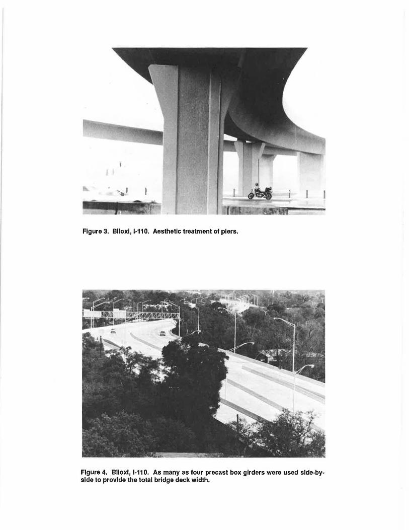
Figure 3. Biioxi, 1-110. Aesthetic treatment of piers.
Figure 4. Biloxi, 1-110. As many as four precast box girders were used side-byside to provide the total bridge deck width.
32 TRANSPORTATION RESEARCH RECORD 1290
Figure 5. Biloxi, 1-110. Balanced-cantilever construction over U.S. 90. Lane closures were made only as segments directly above were placed.
Figure 6. San Antonio "Y". Aerial view of lllA&B Project. Second-level bridges are placed within existing right-of-way. All aspects of highway geometry are accommodated In span-by-span precast segmental construction.
Corven
length. A typical segment weight is 90,000 lbs. Pier segments 9' in length are placed on top of the cast-in-place piers. The segments are assembled using the span-byspan method of construction. (Figures 7 and 8) Twin triangular trusses support the segments temporarily, while closure joints at either end of the span are being cast. Segments .can be delivered on the ground or over the
• completed portion of the bridge deck. A typical span is prestressed with three 12 x 0.6" diameter strand tendons and one 19 x 0.6" diameter strand tendon per web. In addition seven and four strand tendons of 0.6" diameter are placed in the cantilever wings to assure longitudinal continuity.
Pro)ect llB The second leg of the Downtown •y• was Project llB. This structure carries Interstate 35 traffic north away from the intersection of 1-10 and 1-35. The project is 5,817' long along the main lanes. Two ramp structures with a total length of 1,474' complete the bridge layout. The total square footage of this project is 350,055 sq. ft. The typical roadway for this project is 58' wide. Ramp structures as with the IA Project are 26' wide. The 63 main line spans vary in length between 78' and 11 O'. The typical span is 100'.
As in the IA Project, the typical substructure are cast-inplace twin wall piers resting on cast-in-place footings supported by two 48" diameter drilled shafts. Cantilever piers and straddle bents were required on this project as in the first project in order to provide horizontal and vertical clearances above underlying roadways.
A typical segment has a 58' wide top slab and a 1 O' wide bottom slab. The depth of the structure is again 5'-1 O" and the web slopes 2.5:1. The resulting cantilever wings are 22'-6" long. Unlike the IA Project the cantilevers for the llB Project, which vary in thickness from 1 O" to 2'-3", are voided to reduce superstructure dead-load. A typical span on the llB Project is made of 12 typical segments with length of 8' and 5'-6" pier segment halves placed a either end. Different from the IA Project were closure joints were made between the pier segments and the typical segments of the span, the llB Project has closure joints centered over the tops of the piers between pier segment halves.
Construction is again by the span-by-span method and the post-tensioning of a typical span is 3 12 x 0.6" diameter strand tendons and 2 19 x 0.6" diameter strand tendons per web. The post-tensioning is stressed in two stages. First, two tendons of 19 strands each are stressed forming simple spans. Next, the cast-in-place closure joints between the pier halves over the piers are poured and the continuity 12 strand tendons are stressed from both ends of the four span units.
Pro)ect lllA&B The third portion of the Downtown •y• to be designed was the lllA&B Project. (Figures 9 & 10) This structure carries traffic on 1-10 away from the interchange for a length of 8,955'. The three ramp structures have a total length of 2,996'. The precast superstructure of this bridge is similar to the llB Project in that it has a 58' wide top slab. Ramps as before are 26' wide. The deck square footage of this project is 567 ,310 square feet. The main line superstructure has 89 spans varying between 80' and 11 O'. The typical span is again 100'.
33
The substructure for this project is cast-in-place solid rectangular shafts supported by a twin 48" diameter drilled shaft. Solid shafts were used on this project as opposed to the twin walled shafts of the previous two projects as a result of shorting the continuous units to two spans. Special substructure again was required in the form of C-Piers, straddle bents, and T-Piers.
A typical span of 100' was made up of 15 segments at approximately 6' in length. Two pier segment halves at either end of the span, approximately 4'-4" in length complete the typical span. The construction procedure is similar to the llB Project where simple spans are first formed, closure joints placed between the spans and then continuity post-tensioning placed to complete the continuous unit.
Construction Bids for the first section were taken in December 1984, the second section was bid in June 1985, and the third section was bid in May 1986. In each case, the successful contractor bid the alternate precast segmental design. The total area of the three projects is 1,283,980 square feet at a total cost of $43,977 ,000 or $34.25 per square feet.
Austin Bridge Company of Dallas, Texas, is the contractor for the first and second project and The Prescon Corporation of San Antonio, Texas, is the contractor for the third. The first two projects of the Austin Bridge Company were completed in May and September of 1989, and The Prescon Corporation's project was completed in August 1989.
Each contractor established casting yards about nine and six miles, respectively, from the projects and hauled the segments over city streets for a portion of the distance. Segment weight limitations were established to avoid damage to the streets.
Span-by-span was the construction method selected for all projects. Erection trusses support the segments while the match-cast joints are epoxied together and the entire span is post-tensioned with external tendons inside the boxes. Austin Bridge Company placed three sets of erection trusses on their projects while The Prescon Corporation has a single set of trusses. Where space is available, each contractor uses ground-mounted cranes to set segments and move the trusses. However, many of the spans have been erected from the top of the previously completed structure using deck-mounted cranes because of limited space and traffic interference.
Many amenities of urban highways have been incorporated into the structures. Surface drainage is collected in roadway scuppers and carried to the interior of the box and finally discharged through the piers into a storm drainage system. Signal and electrical conduits are cast into the concrete so that the fixtures are attached to the structure without exposed wiring. Sign and luminary supports are bolted onto brackets extend ing from the cantilever wings and in an area that required special protection from hazardous highway cargos; a special barrier was designed and crash tested so that maximum legal loaded vehicles would be safely redirected into the traffic stream without overturning or penetrating the barrier parapet.
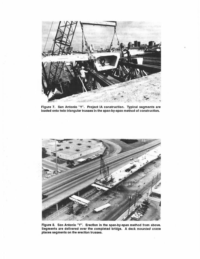
Figure 7. San Antonio "V". Project IA construction. Typical segments are loaded onto twin triangular trusses In the span-by-span method of construction.
Figure 8. San Antonio "V". Erection In the span-by-span method from above. Segments are delivered over the completed bridge. A deck mounted crane places segments on the erection trusses.

\ . '
Figure 9. San Antonio "Y". Project lllA&B construction over active rall lines. Construction from above eliminated traffic disruptions.
Figure 10. San Antonio "Y". Completed Project lllA&B at night. Lighting for atgrade faclllty was provided by fixtures embedded In the elevated structures.
36
Project 3: US 183 - AUSTIN, TEXAS
U.S. Highway 183 serves as a main artery for cross-town traffic in Austin, Texas. To the northwest, U.S. 183 serves as the commuting route to industries such as Texas Instruments, IBM, and 3M. Between the Loop 1 interchange and IH-35, this expressway dually serves to carry local business traffic as well as through traffic to IH-35 and U.S. 290. Heavy congestion during peak operating hours and future traffic projections indicate the need to improve U.S. 183 from the existing six-lane expressway to a six-lane freeway with three-lane one-way frontage roads.
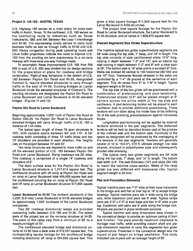
To accomplish these improvements U.S. 183 from RM 620 to east of U.S. 290 was divided into six design sections for the preparation of plans for roadway and bridge construction. Right-of-way limitations in the stretch of U.S. 183 between Peyton Gin Road and IH-35, designated Contract 5, require elevated structures to carry through traffic to the east of IH-35. Existing bridges at Lamar Boulevard divide the elevated structures of Contract 5. The resulting structures are designated the Peyton Gin Road to Lamar Boulevard and Lamar Boulevard to IH-35 elevated bridges. (Figures 11 and 12)
Peyton Gin Road to Lamar Boulevard
Beginning approximately 1,500' north of Peyton Gin Road at Station 332+20, the Peyton Gin Road to Lamar Boulevard elevated bridges will carry through traffic of U.S. 183 a distance of 1.44 miles.
The typical span length of these 76 span structures is 100', with variable spans between 80' and 11 O'. A 56' roadway width consisting of three 12' traffic lanes and two 1 O' shoulders are provided in each direction. Pier heights vary on the project between 10' and 45'.
Two ramp structures are required to move traffic on and off the elevated portion of U.S. 183 between Peyton Gin Road and Lamar Boulevard. Ramp roadways are 26' wide. This roadway is comprised of a single 14' roadway and shoulders of 6'.
The deck surface area for the Peyton Gin Road to Lamar Boulevard structure is 1,017,414 square feet. The northbound structure with off ramp at Peyton Gin Road and on ramp at Lamar Boulevard total 499,458 square feet and the southbound including the on ramp at Peyton Gin Road and off ramp at Lamar Boulevard structure 517,956 square feet.
Lamar Boulevard to IH-35 The northern abutments of the 4,220' (0.8 mile) Lamar Boulevard to IH-35 elevated bridges lie approximately 1,500' southeast of the Lamar Boulevard overpasses.
Two 26' roadway directional ramps are provided connecting traffic between U.S 183 and IH-35. The tallest piers of the project are on the on-ramp structure at IH-35. The piers of this ramp vary from a minimum of 25' to a maximum height of 70'.
The northbound elevated bridge and directional onramp at IH-35 have a deck area of 316,597 square feet. The corresponding square footage for the southbound bridge including directional off ramp is 294,663 square feet. This
TRANSPORTATION RESEARCH RECORD 1290
gives a total square footage 611,260 square feet for the Lamar Boulevard to IH35 structures.
The project total square footage for the Peyton Gin Road to Lamar Boulevard structure, the Lamar Boulevard to IH-35 structure, and all ramps is 1,628,674 square feet.
Precast Segmental Box Girder Superstructure
The mainline typical box girder superstructure segments are 58' wide along the top slab, 7' deep, and 10' in length. The top slab consists of side cantilevered slabs 14'6" long, varying in depth between 1'-3" and 10", and an interior top slab varying in depth between 1 '-2" and 8" with a clear span of 25'. The bottom slab is 16' wide and is a constant 8" thick. Webs are inclined 90 vertical to 100 horizontal (90: 100) and are 1 O" thick. Transverse flexural stresses in the webs are controlled by a 1 '-4 • rib placed at the centerline of each segment. This rib varies from 9" to 1 '-8" in height. Typical segment weight is 60 tons.
The top slab of the box girder will be prestressed with a combination of pretensioning and post-tensioning. Pretensioned strands (0.5" will be placed straight at 6" centers across the entire width of the top slab and cantilevers., A post-tensioning tendon will be placed in each cantilever slab to provide additional prestressing. These tendons will turn down along the inside face of the stiffening rib of the web providing precompression against transverse forces.
Longitudinal post-tensioning will be applied by external tendons anchored in the pier segments. The deflected tendons will be held by deviation blocks cast at the juncture of the inclined web and the bottom slab. Continuity of the spans as designated will be produced by the overlapping of the tendons in the pier segments. Tendons will generally consist of 12 to 19-0.6"), 270 K ultimate strength low relax strands, encased in polyethylene pipe and subsequently grouted after stressing.
The typical ramp box girder segments are 28' wide along the top slab, 7' deep, and 1 O' in length. The bottom slab width is 8'. The web thickness (10") and slope (90:100) to match the mainline cross-section. Webs of the ramp girder are also stiffened with transverse ribs. Typical segment weight is 33 tons.
Pier and Foundation Elements
Typical mainline piers are 7'-0" wide at their base transverse to the bridge axis and flair at their top to 16' to accept bridge bearings. Typical mainline piers are 4' wide along the bridge axis, while expansion joint piers are 6' wide. Typical ramps piers are 4'-6" x 4'-0" at their base and flair to 8" wide at pier top. Expansion joint piers are 6' wide along the bridge axis. All piers are poured-in-place reinforced concrete.
Typical mainline and ramp dimensions were chosen in the conceptual design to provide an optimum pairing of form and function. The piers provide maximum clearance to frontage road traffic, while providing column shaft and pier cap dimensions required to carry the segmental box girder superstructure. Presented in the conceptual design was the impact of pier height on bridge aesthetics. This study indicated use of piers with an average height of 25' .
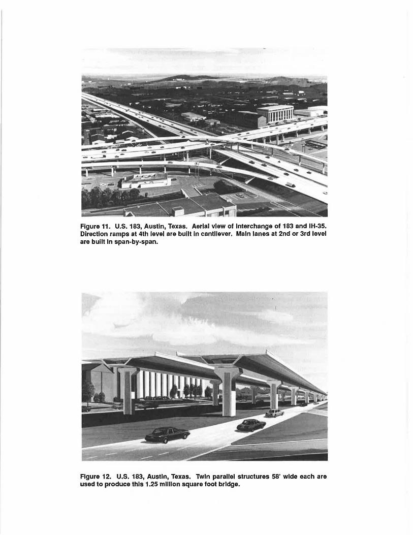
Figure 11. U.S. 183, Austin, Texas. Aerial view of Interchange of 183 and IH-35. Direction ramps at 4th level are built In cantilever. Main lanes at 2nd or 3rd level are built In span-by-span.
Figure 12. U.S. 183, Austin, Texas. Twin parallel structures 58' wide each are used to produce this 1.25 million square foot bridge.

38
Studies in the Preliminary Design focused on two additional aspects of pier aesthetics. These were pier color and texture. Early in the Preliminary Phase it was confirmed that the natural color of the cast concrete would be used. To assist in determining whether or not texturing of exposed pier surfaces was desired, architectural renderings were prepared for various options.
Three of these options are presented in this section for both mainline and ramp typical piers. The first rendering is that in which no texturing is used on any exposed pier face. This is followed by a vertical texturing on the central portion of the transverse pier faces. Finally, texturing on both the transverse and longitudinal faces is presented. Textured surfaces would be provided by form liners attached to the pier forms.
Drilled shafts will transmit bridge reactions to underlying supporting strata. Based on existing soil information, the typical mainline piers rest on two 42" shafts Typical ramp piers are supported by two 36" shafts.
The bridge deck of the U.S. 183 bridges will transmit its reactions to the piers through elestomeric bearings. The horizontal flexibility of the bearings is varied by adjusting the bearing thickness. This control over substructure flexibility permits a more uniform transmission of load to the piers of a continuous unit. Typical span lengths are 100' and a typical unit consists of 6 typical 100' spans.
Construction Methods
The construction method proposed for the elevated U.S. 183 bridges is the span-by-span method utilizing twin triangular assembly trusses.
A typical assembly cycle begins with the assembly trusses resting on the temporary pier brackets of the span to be constructed. Superstructure segments, precast in a casting yard, are delivered over ground or along the completed portion of elevated bridge.
Either a ground based or deck mounted crane lifts the precast segments and places them on rolling supports on the assembly trusses. A hand winch brings the segments along the top cord of the twin triangular trusses to their final location. When all segments are in place, temporary blocking is placed across the closure joints, and a nominal prestress force is applied to insure tight fit of all the precast segments. Closure joint concrete is poured, longitudinal duct work secured, and the post-tensioning tendons threaded and stressed. The construction cycle is completed when the assembly trusses are advanced to the next span.
The assembly trusses for the U.S. 183 bridges may be self-launching to permit truss advancement when ground access is not available. Self launching of the assembly trusses takes place in two phases. At first, the front of the erection truss will ride on the temporary pier bracket of the pier at the open end of construction. The rear of the assembly truss rides along the completed superstructure with the aid of a C-hook and wheel. When the launching nose attached to the front of the assembly trusses lands at the pier bracket of the next pier, it supports the front of the truss eliminating the need for the Chook. The rear of the truss now rides along the temporary pier bracket at the open end of construction.
TRANSPORTATION RESEARCH RECORD 1290
The span-by-span method of erection will accommodate all variations in span length on the U.S. 183 bridges except for the 180' span of the directional interchange ramp at IH-35. A recently developed technique of balanced cantilever construction incorporating the twin triangular trusses to provide cantilever stability will be used for this span. The construction sequence of the five span continuous unit of the directional ramp is as follows:
1. The first span of 120' is built in conventional span-byspan fashion.
2. The assembly trusses are advanced across the 135' span adjacent to the main span. When secured, it provides the stability against cantilever overturning moments developed during balanced cantilever construction. Precast segments of the side span can be placed all at one time leaving gaps between the segments or placed one by one and attached directly to the cantilever.
The sequence of placing segments in cantilever is to always attach the side span segment prior to the placing of its balancing segment in the main span. In this way, the cantilever overturning is resisted directly by the temporary trusses.
3. After the cantilever is complete, the assembly trusses are taken down by crane and transported to the East side of IH-35 and assembled in the 135' span following the main span.
Balanced cantilever construction resumes, as described above, always assembling the segments of the side span to the cantilever prior to placing main span segments.
4. Once the balanced cantilever construction is completed for the second cantilever, the main span closure pour is made, and continuity post-tensioning of the main span is stressed completing main span construction. Following this, the remaining segments of the 135' span are assembled and continuity prestress is applied.
5. To complete the five span unit, the span-by-span trusses are advanced to the 120' span and typical span-byspan construction takes place.
CONCLUSIONS
• Precast segmental concrete box girder construction technology has been used successfully to minimize on-site construction time, speed erection and eliminate interference with traffic. • The second-level structure utilizes a minimum of ground space, which permits a doubling of capacity with minimum acquisition of rights of way in congested urban areas. • Transitions from single boxes to twin boxes for ramp structures are totally precast. • Complex geometry was accomplished by using the shortline casting technique. • Span-by-span ~rection method previously used for long bridges over water is extremely efficient in constructing urban structures with complex geometry. • Span-by-span erection takes place with segment delivery over the completed portion of bridge and segment placement by deck mounted crane. • Balanced-cantilever construction takes place over Interstates and U.S. highways with minimal disruption.