traumacad user’s guide - ipro inc +972-3-923-6413 us headquarters 5575 sterrett place suite 250...
TRANSCRIPT

TraumaCad®
User’s Guide
Version 2.2
A Voyant Health Ltd. Document
Copyright 2010

Important Notice
TraumaCad® User's Guide
ii
Important Notice Copyright and Trademark Notices
All contents of this document are Copyright 2010 Voyant Health Ltd.
All rights reserved. The trademarks, logos and service marks displayed on this document are the
property of Voyant Health Ltd. or other third parties. Users are not permitted to use these
trademarks, logos and service marks without the prior written consent of Voyant Health Ltd., or
such third parties as may own them.
Limited License
Voyant Health Ltd. hereby gives license to review these documents solely for non-commercial use
within your organization, provided that you do not modify the content of the documents and
provided any copies made retain all copyright and other proprietary notices contained therein. The
information provided in these documents is permitted solely to users to provide information in
support of Voyant Health Ltd. products. No other use of the information provided hereunder is
authorized.
Nothing contained herein shall be construed as conferring by implication, estoppel or otherwise any
license or right under any patent or trademark of Voyant Health Ltd. or any third party. Except as
expressly provided above, nothing contained herein shall be construed as conferring any license or
right under any Voyant Health Ltd. or third party copyright.
Limitation of Liability
Information provided on this documents is provided "AS IS" and is provided without warranty of
any kind, either express or implied, including, without limitation, warranties of merchantability,
fitness for a particular purpose, and non-infringement. Voyant Health Ltd. uses reasonable efforts to
include accurate and timely information on this web site and periodically updates the information
without notice. However, Voyant Health Ltd. makes no warranties or representations as to the
accuracy or completeness of such information, and Voyant Health Ltd. assumes no liability or
responsibility for errors or omissions in the content of this documents. Your use of these documents
is AT YOUR OWN RISK. Under no circumstances and under no legal theory or provision shall
Voyant Health Ltd. be liable to you or any other person for any direct, indirect, special, incidental,
exemplary, or consequential damages arising from your access to, or use of, these documents.
Product information is subject to change without notice. Changes, if any, will be incorporated in new
editions of publications provided in these documents. Voyant Health Ltd. retains the right to make
improvements and/or changes in the products and/or the programs described in the publications and
information provided on these documents at any time and without prior notice. Mention of non-
Voyant Health Ltd. products or services is for information purposes only and constitutes neither an
endorsement nor a recommendation of such products or services.
Important Notice
TraumaCad® User's Guide
iii
Third-Party Information
These documents may contain information of parties other than Voyant Health Ltd. Such
information is provided for your convenience and reference only. The said information is not under
the control of Voyant Health Ltd., and Voyant Health Ltd. is not responsible for the contents of any
of such information. The inclusion of this information does not imply any association with their
operators or any endorsement of the said third parties by Voyant Health Ltd.
Disclaimer
This software is intended as a decision support system for persons who have received appropriate
medical training, and should not be used as a sole basis for making clinical decisions pertaining to
patient diagnosis, care, or management. All information derived from the software must be clinically
reviewed regarding its plausibility before use in treating patients. Any deviation of the application of
medical information from the program, other than the original design or intended use there of, is not
advised and considered a misuse of the software product. For additional guidance, see published
studies.
0344
This device complies with the Requirements of the 93/42/EEC Directive
Concerning Medical Devices, as amended by Council Directive 2007/47/EC.
Authorized representative address:
CEpartner4U B.V.
Esdoornlaan 13
3951 DB Maarn
The Netherlands
Phone: +31.343.442.524
Fax: +31.343.442.162
Catalog Number: MK3U00074 ver G

Table of Contents
TraumaCad® User's Guide
iv
Table of Contents
About This Guide.............................................................................................................. viii
Audience .............................................................................................................................. ix
Contacting Us ........................................................................................................................x
Safety Symbols .................................................................................................................... xi
Chapter 1, Getting Started with TraumaCad.............................................................. 1
What is TraumaCad? ...........................................................................................................1
TraumaCad Workflow .........................................................................................................2 Selecting the Procedure ...................................................................................................3 Importing the Digital X-ray .............................................................................................3 Specifying Anatomical Orientation .................................................................................3 Displaying the Image .......................................................................................................3 Calibrating the Image ......................................................................................................3 Performing Pre-operative Evaluation and Planning ........................................................4 Saving and Archiving ......................................................................................................4
Client/Server or Standalone .................................................................................................5
System Requirements ...........................................................................................................6
Launching TraumaCad .......................................................................................................7 Procedures .......................................................................................................................9 My OrthoWeb Cases ..................................................................................................... 10 My OrthoWeb Account ................................................................................................. 11 My Local Cases ............................................................................................................. 12 News from Voyant Health ............................................................................................. 13
Quick Tour of the TraumaCad Interface ......................................................................... 14 Menu Bar ....................................................................................................................... 15 Toolbar .......................................................................................................................... 19 TraumaCad Right-click Menus ..................................................................................... 23 Grouping Objects .......................................................................................................... 24
Chapter 2, Preparing the Image ................................................................................. 25
Loading Images from a PACS ........................................................................................... 26 Finding the Patient ......................................................................................................... 26 Selecting the Patient’s Images ....................................................................................... 27 Compressing Images ..................................................................................................... 28
Specifying Anatomical Orientation ................................................................................... 30
Multiple Views .............................................................................................................. 31

Table of Contents
TraumaCad® User's Guide
v
Calibrating the Image ........................................................................................................ 31 X-ray Scaling ................................................................................................................ 32 Calibration Sphere ........................................................................................................ 32 OrthoMark .................................................................................................................... 33 Calibration Window ...................................................................................................... 34 Calibrating an Image ..................................................................................................... 36
Chapter 3, TraumaCad Pre-operative Procedures ................................................... 39 Building a Kit ............................................................................................................... 42
Templating .......................................................................................................................... 43 Selecting an Implant ..................................................................................................... 44 Specifying Implant Properties ...................................................................................... 47 Positioning an Implant .................................................................................................. 49
Trauma Procedures ........................................................................................................... 50 Specifying the Anatomical Region ............................................................................... 51 Reducing the Bone Fragments ...................................................................................... 53 Special Trauma Template Features ............................................................................... 56
3D Suite (Optional) ............................................................................................................ 61 Opening a 3D Image ..................................................................................................... 62 Adding a 3D Template .................................................................................................. 66
Auto-Hip Procedure........................................................................................................... 69
Deformity Procedure ......................................................................................................... 69
Chapter 4, Measuring the Anatomy ........................................................................... 71
Generic Tools...................................................................................................................... 72 Ruler Tool ..................................................................................................................... 72 Circle Tool .................................................................................................................... 73 Angle Tool .................................................................................................................... 73 Interline Tool ................................................................................................................ 74 Line Tool ...................................................................................................................... 74 Free Hand Line Tool ..................................................................................................... 75 Text Annotations .......................................................................................................... 76
Auto-Hip Measurements ................................................................................................... 77
Deformity Measurements .................................................................................................. 80 Limb Alignment Analysis ............................................................................................. 80
Hip Measurements ............................................................................................................. 94 Hip Deformity Analysis ................................................................................................ 95 Leg Length Discrepancy Tool .................................................................................... 100 Acetabular Index ......................................................................................................... 101 VCA Angle of Lequesne............................................................................................. 102 Cup Version ................................................................................................................ 103 Center of Rotation ....................................................................................................... 104

Table of Contents
TraumaCad® User's Guide
vi
Stem Version ............................................................................................................... 105
Knee Measurements ......................................................................................................... 106 Limb Alignment Analysis ........................................................................................... 106 Center Line Finder ....................................................................................................... 107 Simple Line ................................................................................................................. 108 High Tibial Osteotomy ................................................................................................ 109 Tibial Cutting .............................................................................................................. 110 Joint Line ..................................................................................................................... 111
Pediatric Measurements ................................................................................................... 112 Hip Deformity Analysis .............................................................................................. 112 Limb Alignment Analysis ........................................................................................... 117 Acetabular Index ......................................................................................................... 118 Reimer’s Index ............................................................................................................ 119 VCA Angle of Lequesne ............................................................................................. 120 Neck Shaft Angle ........................................................................................................ 121 Head Shaft (Slip) Angle .............................................................................................. 122 Articulo-trochanteric Distance .................................................................................... 123 Epiphyseal Index ......................................................................................................... 124 Tibiofemoral Angle ..................................................................................................... 125 Metaphyseal-Diaphyseal Angle ................................................................................... 126
Trauma Measurements .................................................................................................... 127 Limb Alignment Analysis ........................................................................................... 127 Diaphyseal Fracture Angulation .................................................................................. 128 Metaphyseal Fracture Angulation ............................................................................... 129 Center Line Finder ....................................................................................................... 129 Simple Line ................................................................................................................. 130 Roof Arc ...................................................................................................................... 130 Joint Line ..................................................................................................................... 131
Spine Measurements ......................................................................................................... 132 Vertebrae Labeling ...................................................................................................... 132 Cobb Angle.................................................................................................................. 135 Double Cobb Angle ..................................................................................................... 136 Triple Cobb Angle ....................................................................................................... 137 Pelvic Radius Angle .................................................................................................... 137 Sacral Obliquity ........................................................................................................... 139 Coronal Balance .......................................................................................................... 140 Sagittal Balance ........................................................................................................... 141 Spondylolysthesis ........................................................................................................ 142 Thoracic Kyphosis Angle ............................................................................................ 143 Thoracic Trunk Shift ................................................................................................... 144 T1 Tilt Angle ............................................................................................................... 145

Table of Contents
TraumaCad® User's Guide
vii
Lumbar Lordosis Angle .............................................................................................. 146 Spine Slip Angle ......................................................................................................... 147
Foot and Ankle Tools ....................................................................................................... 148 Foot Osteotomies Wizard ........................................................................................... 148 Hallux Valgus Angle .................................................................................................. 154 Hallux Valgus Interphalangeus Angle ........................................................................ 155 Intermetatarsal Angle .................................................................................................. 156 DMAA Distal Metatarsal Articular Angle .................................................................. 157
PMAA Proximal Metatarsal Articular Angle ............................................................. 158 Talar Tilt ..................................................................................................................... 159
Upper Limb Measurements ............................................................................................ 160 Center Line Finder ...................................................................................................... 160 Simple Line ................................................................................................................. 160 Joint Line .................................................................................................................... 161
CORA Tools ..................................................................................................................... 161
Center Line Finder ...................................................................................................... 161 Joint Line .................................................................................................................... 161
Growth Calculator ........................................................................................................... 163
Chapter 5, Reports ..................................................................................................... 169
Generating Reports .......................................................................................................... 169
Appendix A, Installing TraumaCad ......................................................................... 173
Installing TraumaCad ..................................................................................................... 173
How to Install TraumaCad ............................................................................................. 175
Appendix B, Standalone Usage ................................................................................. 179
Setting the PACS Configuration (Optional) .................................................................. 180
Importing Images from a CD .......................................................................................... 181
Capturing Images from the Screen ................................................................................ 182
Appendix C, Managing Implant Templates ............................................................ 183
Importing Implant Templates ......................................................................................... 184
Templates Manager ......................................................................................................... 185
Other Templates Manager Options ................................................................................ 187 Searching for Templates ............................................................................................. 187 Remove Selected Templates ....................................................................................... 187 Change Templates Folder ........................................................................................... 188
Index ............................................................................................................................ 189

About This Guide
TraumaCad® User's Guide
viii
About This Guide This guide is intended for surgeons who are performing pre-operative evaluation and
planning for orthopedic procedures.
This guide contains the following chapters:
Chapter 1, Getting Started with TraumaCad, page 1, describes the purpose of
TraumaCad, its system requirements, how to install it, how to launch it and
provides a quick tour through its interface.
Chapter 2, Preparing the Image, page 25, describes how to use TraumaCad to
load the required images, specify their anatomical orientation and calibrate the
images.
Chapter 3, TraumaCad Pre-operative Procedures, page 39, describes how to
use TraumaCad for pre-operative evaluation and planning for a variety of
orthopedic procedures.
Chapter 4, Measuring the Anatomy, page 71, describes how to use the various
tools provided by TraumaCad to measure the anatomy represented in an image. It
also describes how to take anatomical measurements, compare them to normative
standards and simulate corrective procedures for limb alignment analysis.
Chapter 5, Reports, page 169, describes how to generate a report.
Appendix A, Installing TraumaCad, page 173, describes how to install
TraumaCad for standalone operation.
Appendix B, Standalone Usage, page 179, describes several procedures that may
be required in standalone mode.
Appendix C, Managing Implant Templates, page 183, describes how to import
and manage implant templates in the TraumaCad system.

Audience
TraumaCad® User's Guide
ix
Audience
This guide is intended for surgeons and other medical personnel who want to perform
pre-operative surgical planning and evaluate images.
TraumaCad operates in two modes: standalone mode and web client mode.
Procedures and sections in the guide are marked to indicate whether they apply to
standalone mode ( ) or web client mode ( ). You only need to read those
sections relevant to your work mode when using the TraumaCad application.

Contacting Us
TraumaCad® User's Guide
x
Contacting Us
International Headquarters
35 Efal Street
Petach-Tikva, 49511
Israel
Telephone +972-3-929-0929
Fax +972-3-923-6413
US Headquarters
5575 Sterrett Place
Suite 250
Columbia MD 21044
USA
Telephone 866-717-0272
Fax 801-881-5239
UK Office
Toll Free 00-800-9290-9290
Fax +44 207 692 7865

Safety Symbols
TraumaCad® User's Guide
xi
Safety Symbols
The following symbols are used throughout the documentation. Please pay particular
attention at specific points in a procedure when one of the following messages
appears.
WARNING!
A WARNING! denotes a hazard. It calls attention to a procedure that, if not correctly
performed or adhered to, could result in injury or loss of life. Do not proceed beyond a
warning note until the indicated conditions are fully understood and met.
NOTE:
Notes provide pertinent information to help obtain optimum performance from the program.
TIP:
This is a tip providing useful suggestions and information.

Safety Symbols
TraumaCad® User's Guide
xii
This page is intentionally left blank.
Getting Started with TraumaCad
TraumaCad® User's Guide
1
3Chapter 1
Getting Started with
TraumaCad
NOTE:
Procedures and sections in the guide are marked to indicate whether they apply to
standalone mode ( ) or web client mode ( ).
What is TraumaCad?
TraumaCad is for assisting healthcare professionals in preoperative planning of
orthopedic surgery. Clinical judgments and experience are required to properly use
the software.
TraumaCad allows surgeons to evaluate and manipulate digital images while
performing various pre-operative surgical planning and evaluation of images.
TraumaCad enables increased productivity and improves patient safety. The program
features full PACS integration and an extensive regularly updated library of digital
templates from leading manufacturers.
TraumaCad provides easy-to-use solutions for various orthopedic subspecialties:
Hip
Knee
Pediatric
Trauma
Spine
Foot and Ankle
Upper Limb
3D Suite
Auto-Hip

Getting Started with TraumaCad
TraumaCad® User's Guide
2
Deformity
TraumaCad Workflow
The following provides a chronological overview of the process of using TraumaCad.
NOTE:
For standalone TraumaCad usage, you must first install the application. See page 173 for
details.
Selecting the Procedure
Importing the Digital X-ray
Specifying Anatomical Orientation
Displaying the Image
Calibrating the Image
Performing Pre-operative
Evaluation and Planning
Saving and Archiving
page 3
page 3
page 3
page 3
page 3
page 4
page 4
NOTE:
Templates are updated automatically. To import a missing template, see page 183.

Getting Started with TraumaCad
TraumaCad® User's Guide
3
Selecting the Procedure
The TraumaCad application is procedure-oriented, which means that you must select
the relevant surgical or analysis procedure to be performed on the patient as your first
step when accessing the application. The procedure you choose determines the
specific templates and measurement tools that can be used in the application. See
Chapter 3, TraumaCad Pre-operative Procedures, on page 39.
Importing the Digital X-ray
TraumaCad is transparently integrated with the PACS system and enables full access
to its patient images and information. TraumaCad provides a variety of options for
finding a specific patient of interest. After you have found the patient, you can select
the images in which you are interested. See page 26 for details.
Specifying Anatomical Orientation
After an image is displayed, whether it was imported from a PACS system or a CD,
you must specify its anatomical orientation. See page 28 for details.
Displaying the Image
TraumaCad supports DICOM and enables you to import and export any PACS file
(X-ray, CT or MR) from a central PACS system, a CD or from a local workstation.
JPG, scanner or digital camera images can also be imported. See page 25 for details.
You can also import images from OrthoWeb, as described in the My OrthoWeb Cases
section on page 10.
Calibrating the Image
TraumaCad’s automatic calibration tool facilitates precise calibration to the actual
bone size. See page 25 for details.

Getting Started with TraumaCad
TraumaCad® User's Guide
4
Performing Pre-operative Evaluation
and Planning
TraumaCad provides easy-to-use solutions for various orthopedic subspecialties:
Hip, page 94
Knee, page 106
Pediatric, page 112
Trauma, page 127
Spine, page 132
Foot and Ankle, page 148
Upper Limb, page 160
3D Suite, page 61
Auto-Hip, page 77
Deformity, page 80
Saving and Archiving
Once the planning of a procedure is completed, a full report is saved, which includes
the image, the implants and the measurements that were marked on it. This report can
be stored in the patient’s PACS file, locally, uploaded to OrthoWeb or sent by
OrthoFlow.
NOTE:
In addition, TraumaCad provides a series of anatomical measurement tools in manual,
semi-automatic and automatic mode. In addition to length, width and diameter, these tools
measure leg length discrepancy, Cobb angle, mechanical and anatomic axis
measurement, mal-alignment tests and more. These tools can be used on an image at any
time. For more information, see page 71.
TraumaCad also provides a Growth Analysis tool, which provides various options for
predicting the growth of a particular anatomy in pediatric orthopedics. For more
information, see page 163.

Getting Started with TraumaCad
TraumaCad® User's Guide
5
Client/Server or Standalone
TraumaCad is installed and runs locally on your computer and interacts with a PACS
system. Both a web client (client/server) and a standalone version of TraumaCad are
available.
The client/server version is comprised of a server application that is set up by the
administrator, and client applications that run on specific computers.
The standalone version runs on a specific computer only and stores all its files, such
as its configuration and implant templates, on that specific computer.
These two types of applications operate in a very similar manner and there are only
slight differences in functionality, as described below.
Client/Server Functionality
All the functionality described in this guide is available in the client/server version
except for those listed below. The features that are not available are performed by the
administrator. Some of these administrator features apply to all the TraumaCad
applications running in an organization, such as the library of implant templates, and
some are user-specific according to the user that logs in to a client:
There is no need to specify the connection properties between TraumaCad and the
PACS system. Therefore, the PACS Configuration option is not applicable in the
client version.
An organization that runs the client/server version is assigned a certain number of
licenses, and the quantity of TraumaCad applications that can run simultaneously
(concurrent users) is determined by this license.
The following are handled by the administrator, and the client does not need to
perform them:
Import Image option
Import DICOM Folder option
Query button
Download Templates option
Screen Capture option
Standalone Functionality
All the functionality described in this guide is available in the standalone version.
Getting Started with TraumaCad
TraumaCad® User's Guide
6
System Requirements
Hardware
1GB RAM or more
Processor: P4 2.8 GHz or higher
Hard Drive:
Up to 75 MB for the software
Up to 2GB for digital templates
Minimal screen resolution: 1024 x 768
64MB graphics card (For 3D Suite)
Open Internet access (OrthoWeb usage / templates updates)
Software
Windows XP professional 32bit/64bit or Windows VISTA business 32bit/64bit
(English should be the default OS language – other languages can coexist)
Windows XP SP2 / SP3 or Windows VISTA SP1
MS windows update (all patches & hot fixes available at Microsoft windows
update)
MS .NET Framework version 2.0 and 3.5
DirectX 9.0 or up
Internet Explorer 6.0 Service Pack 1 (or above)
I386 directory from the installation CD
Acrobat Reader
VNC, pcAnywhere or MS Terminal (Remote Desktop connection) -
recommended for installation and on going support
NOTE:
To install TraumaCad Workstation, you must be logged on as a user with
administrative privileges.
Clinical Requirements
To perform accurate templating, the image should be calibrated. Image requirements
may differ according to the image source:
Uncalibrated Images: A metal calibration sphere with a known diameter
(typically one inch) must be placed at the bone level prior to taking the image.
DICOM Images with a Preset Calibration Attribute Acquired from the
Modality: There is no need for a physical marker.

Getting Started with TraumaCad
TraumaCad® User's Guide
7
Launching TraumaCad
TraumaCad requires an activation key to operate and must be connected to the Web
the first time it is launched. A trial activation key is valid for 30 days, after which
you can contact your system administrator or Voyant Health sales for a permanent
one.
► To launch TraumaCad:
1 Double-click the TraumaCad icon that was installed on your desktop:
If this is not the first time that TraumaCad is launched on this computer, the main
window is displayed, as shown on page 8.
For first time activation, enter the required information in the window below and
click OK:
2 After entering a valid activation key, the Online Activation button becomes
active. Enter information about yourself in the displayed window and click
OK.
Enter key (provided on CD or sent by Voyant Health)
Getting Started with TraumaCad
TraumaCad® User's Guide
8
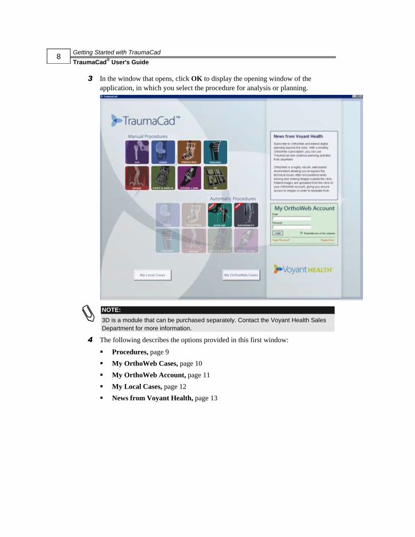
3 In the window that opens, click OK to display the opening window of the
application, in which you select the procedure for analysis or planning.
NOTE:
3D is a module that can be purchased separately. Contact the Voyant Health Sales
Department for more information.
4 The following describes the options provided in this first window:
Procedures, page 9
My OrthoWeb Cases, page 10
My OrthoWeb Account, page 11
My Local Cases, page 12
News from Voyant Health, page 13

Getting Started with TraumaCad
TraumaCad® User's Guide
9
Procedures
The TraumaCad application is procedure-oriented. This means that you must select
the relevant surgical or analysis procedure to be performed on the patient as your first
step when accessing the application. Only the relevant templates and measurements
for the procedure chosen are displayed.
NOTE:
3D is a module that can be purchased separately. Contact the Voyant Health Sales
Department for more information.
Click the icon corresponding to the surgical or analysis procedure to be performed.
The procedures are divided into automatic procedures and manual procedures, as
follows:
Automatic Procedures
AUTO-HIP Page 69
DEFORMITY Page 69
After you select a procedure the TraumaCad main window opens, as shown on page 8.
NOTE:
Future versions of TraumaCad will provide more automatic procedures.
Manual Procedures
HIP Page 94
KNEE Page 106
PEDIATRIC Page 112
TRAUMA Page 127

Getting Started with TraumaCad
TraumaCad® User's Guide
10
SPINE Page 132
FOOT and ANKLE Page 148
UPPER LIMB Page 160
3D Page 61
My OrthoWeb Cases
Click the button on the main splash screen to access the cases that
you saved in OrthoWeb, as shown below:
Getting Started with TraumaCad
TraumaCad® User's Guide
11
You can access your account using the My OrthoWeb Account option, as described
below.
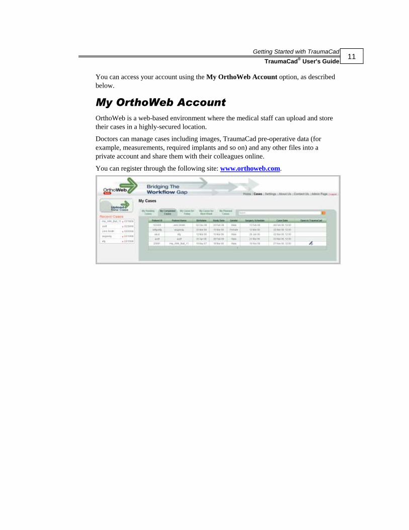
My OrthoWeb Account
OrthoWeb is a web-based environment where the medical staff can upload and store
their cases in a highly-secured location.
Doctors can manage cases including images, TraumaCad pre-operative data (for
example, measurements, required implants and so on) and any other files into a
private account and share them with their colleagues online.
You can register through the following site: www.orthoweb.com.
Getting Started with TraumaCad
TraumaCad® User's Guide
12
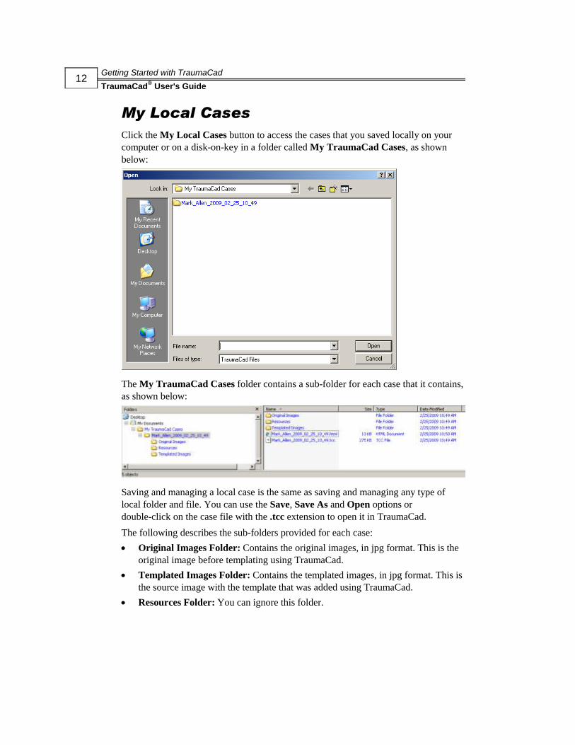
My Local Cases
Click the My Local Cases button to access the cases that you saved locally on your
computer or on a disk-on-key in a folder called My TraumaCad Cases, as shown
below:
The My TraumaCad Cases folder contains a sub-folder for each case that it contains,
as shown below:
Saving and managing a local case is the same as saving and managing any type of
local folder and file. You can use the Save, Save As and Open options or
double-click on the case file with the .tcc extension to open it in TraumaCad.
The following describes the sub-folders provided for each case:
Original Images Folder: Contains the original images, in jpg format. This is the
original image before templating using TraumaCad.
Templated Images Folder: Contains the templated images, in jpg format. This is
the source image with the template that was added using TraumaCad.
Resources Folder: You can ignore this folder.

Getting Started with TraumaCad
TraumaCad® User's Guide
13
TraumaCad Case (tcc): This file has the same name as the case. It is the actual
locally-stored case with the file extension of .tcc. This file is ciphered and
password-protected. This file type is associated in Windows with TraumaCad and
automatically opens in the TraumaCad interface.
HTML Report: A report is created automatically for each case. It provides a
summary of the pre-planning, showing all source images, templated images and
providing details about the template, its position and all measurements, as shown
below:
News from Voyant Health
Voyant Health-related news is provided in this area from an RSS (Really Simple
Syndication) newsfeed.

Getting Started with TraumaCad
TraumaCad® User's Guide
14
Quick Tour of the TraumaCad Interface
This section provides a brief overview of the features of the TraumaCad application,
and describes its main window, menu bar and toolbar. The main window displays a
list of patients and their images. It also serves as the main work area in which you can
measure anatomy, select an appropriate implant or plan for an operation.
The main window contains the following areas:
Menu Bar, page 15
Toolbar, page 19
Find Patients and Images, page 26
Image Compression, page 28
Import Images, page 25
Status Bar: Indicates the status of the application
TIP:
All TraumaCad options are accessible from both the toolbar and the menu bar.
Menu bar
Toolbar
Status Bar
Image Compression
Import Images Area
Find Patients and Images
Getting Started with TraumaCad
TraumaCad® User's Guide
15
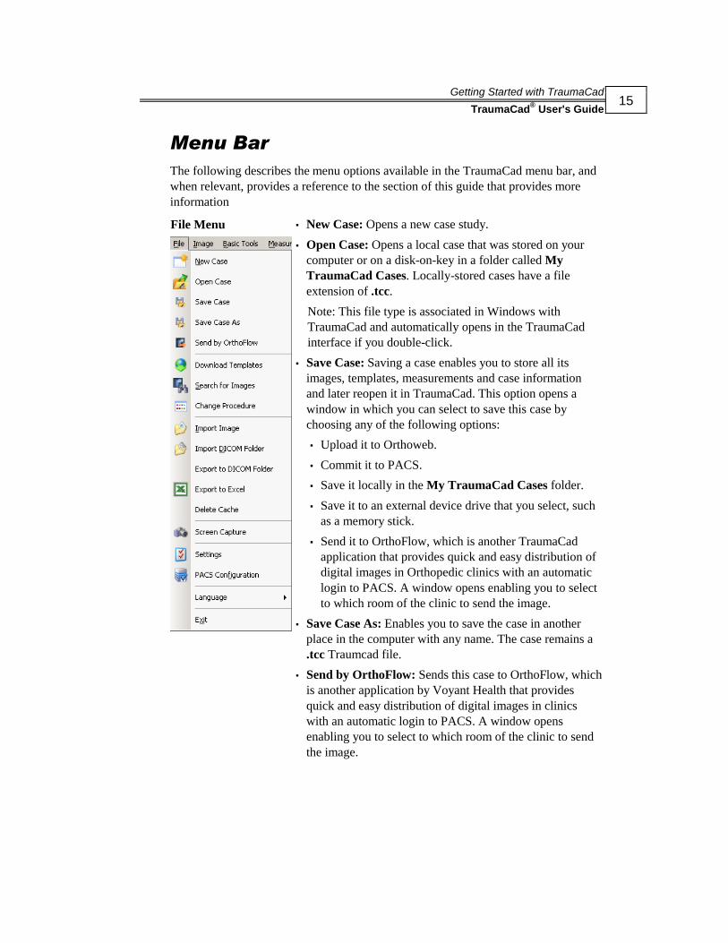
Menu Bar
The following describes the menu options available in the TraumaCad menu bar, and
when relevant, provides a reference to the section of this guide that provides more
information
File Menu
▪ New Case: Opens a new case study.
▪ Open Case: Opens a local case that was stored on your
computer or on a disk-on-key in a folder called My
TraumaCad Cases. Locally-stored cases have a file
extension of .tcc.
Note: This file type is associated in Windows with
TraumaCad and automatically opens in the TraumaCad
interface if you double-click.
▪ Save Case: Saving a case enables you to store all its
images, templates, measurements and case information
and later reopen it in TraumaCad. This option opens a
window in which you can select to save this case by
choosing any of the following options:
▪ Upload it to Orthoweb.
▪ Commit it to PACS.
▪ Save it locally in the My TraumaCad Cases folder.
▪ Save it to an external device drive that you select, such
as a memory stick.
▪ Send it to OrthoFlow, which is another TraumaCad
application that provides quick and easy distribution of
digital images in Orthopedic clinics with an automatic
login to PACS. A window opens enabling you to select
to which room of the clinic to send the image.
▪ Save Case As: Enables you to save the case in another
place in the computer with any name. The case remains a
.tcc Traumcad file.
▪ Send by OrthoFlow: Sends this case to OrthoFlow, which
is another application by Voyant Health that provides
quick and easy distribution of digital images in clinics
with an automatic login to PACS. A window opens
enabling you to select to which room of the clinic to send
the image.

Getting Started with TraumaCad
TraumaCad® User's Guide
16
▪ Download Templates: Downloads templates of implants
from Voyant Health’s global repository to your computer.
▪ Search for Images: Searches for and adds an image while
performing a procedure.
▪ Change Procedure: Changes the surgical or analysis
procedure for a given patient after your initial procedure
selection for this patient. See page 9.
▪ Import Image: Imports a single image file. See page 181.
▪ Import DICOM Folder: Imports a folder of DICOM
images to your local cache. See page 181.
▪ Export to DICOM Folder: Saves the DICOM image on
the local PC as a DICOM folder.
▪ Export to Excel: Exports the measurements to an Excel
sheet. This option is especially suited for research, since
each measurement is added as a row in the Excel sheet file
that you specify. This enables you to perform numerous
measurements, even on different images, and to store them
in the same Excel sheet, with each measurement as a row.
▪ Delete Cache: Clears the cache of images on your local
computer.
▪ Screen Capture: Captures any image that is displayed on
the screen into TraumaCad. See page 182.
▪ Settings: Defines settings for the TraumaCad application.
▪ PACS Configuration: Configures the connection
properties between TraumaCad and the PACS system. See
page 180.
▪ Language: Chooses the language for displaying the
TraumaCad interface.
▪ Exit: Closes the application.

Getting Started with TraumaCad
TraumaCad® User's Guide
17
Image Menu
▪ Rot. 90° CW (clockwise): Rotates the image 90°
clockwise.
▪ Rot. 90° CCW (counter-clockwise): Rotates the image
90° counter-clockwise.
▪ Rot. 180°: Rotates the image 180°.
▪ Vertical Flip: Flips the image vertically.
▪ Horizontal Flip: Flips the image horizontally.
▪ Invert Image: Reverses the areas of black/white on the
image.
▪ Group: Groups multiple objects so they can be moved
together as a single object. See page 24 for details.
▪ UnGroup: Removes objects from a group.
▪ Copy to Clipboard: Copies the displayed image to the
clipboard, including the implants, textual annotations and
measurement tools that you added using TraumaCad.
From there you can paste it to any other application.
Basic Tools Menu
▪ Move: Moves the selected object by dragging the mouse.
▪ Pan: Moves the image itself.
▪ Zoom: Zooms in (enlarges) or zooms out (shrinks) the
image view.
▪ Window Level: Enhances the visible distinction between
contrasting tissue regions by manipulating the brightness
and contrast.
▪ Restore Original W/L: Returns the image’s contrast and
brightness settings to their original values.
▪ Fragments Submenu: See pages 54 through 55 for more
details.
Getting Started with TraumaCad
TraumaCad® User's Guide
18
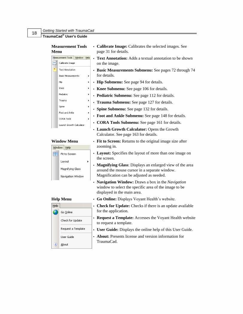
Measurement Tools
Menu
▪ Calibrate Image: Calibrates the selected images. See
page 31 for details.
▪ Text Annotation: Adds a textual annotation to be shown
on the image.
▪ Basic Measurements Submenu: See pages 72 through 74
for details.
▪ Hip Submenu: See page 94 for details.
▪ Knee Submenu: See page 106 for details.
▪ Pediatric Submenu: See page 112 for details.
▪ Trauma Submenu: See page 127 for details.
▪ Spine Submenu: See page 132 for details.
▪ Foot and Ankle Submenu: See page 148 for details.
▪ CORA Tools Submenu: See page 161 for details.
▪ Launch Growth Calculator: Opens the Growth
Calculator. See page 163 for details.
Window Menu
▪ Fit to Screen: Returns to the original image size after
zooming in.
▪ Layout: Specifies the layout of more than one image on
the screen.
▪ Magnifying Glass: Displays an enlarged view of the area
around the mouse cursor in a separate window.
Magnification can be adjusted as needed.
▪ Navigation Window: Draws a box in the Navigation
window to select the specific area of the image to be
displayed in the main area.
Help Menu
▪ Go Online: Displays Voyant Health’s website.
▪ Check for Update: Checks if there is an update available
for the application.
▪ Request a Template: Accesses the Voyant Health website
to request a template.
▪ User Guide: Displays the online help of this User Guide.
▪ About: Presents license and version information for
TraumaCad.
Getting Started with TraumaCad
TraumaCad® User's Guide
19
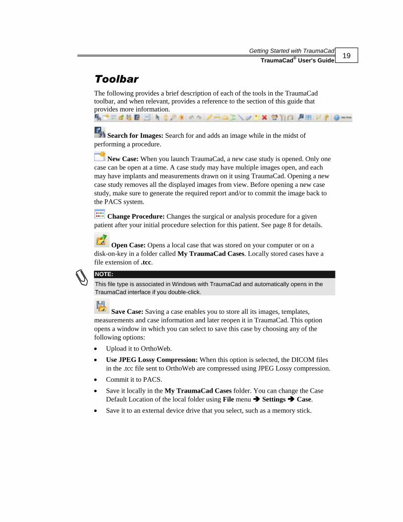
Toolbar
The following provides a brief description of each of the tools in the TraumaCad
toolbar, and when relevant, provides a reference to the section of this guide that
provides more information.
Search for Images: Search for and adds an image while in the midst of
performing a procedure.
New Case: When you launch TraumaCad, a new case study is opened. Only one
case can be open at a time. A case study may have multiple images open, and each
may have implants and measurements drawn on it using TraumaCad. Opening a new
case study removes all the displayed images from view. Before opening a new case
study, make sure to generate the required report and/or to commit the image back to
the PACS system.
Change Procedure: Changes the surgical or analysis procedure for a given
patient after your initial procedure selection for this patient. See page 8 for details.
Open Case: Opens a local case that was stored on your computer or on a
disk-on-key in a folder called My TraumaCad Cases. Locally stored cases have a
file extension of .tcc.
NOTE:
This file type is associated in Windows with TraumaCad and automatically opens in the
TraumaCad interface if you double-click.
Save Case: Saving a case enables you to store all its images, templates,
measurements and case information and later reopen it in TraumaCad. This option
opens a window in which you can select to save this case by choosing any of the
following options:
Upload it to OrthoWeb.
Use JPEG Lossy Compression: When this option is selected, the DICOM files
in the .tcc file sent to OrthoWeb are compressed using JPEG Lossy compression.
Commit it to PACS.
Save it locally in the My TraumaCad Cases folder. You can change the Case
Default Location of the local folder using File menu Settings Case.
Save it to an external device drive that you select, such as a memory stick.

Getting Started with TraumaCad
TraumaCad® User's Guide
20
Send it to OrthoFlow, which is another TraumaCad application that provides
quick and easy distribution of digital images in the Orthopedic clinics with an
automatic login to PACS. A window opens enabling you to select to which room
of the clinic to send the image.
Annotation: Selects the positioning and orientation of the text on the saved
image.

Getting Started with TraumaCad
TraumaCad® User's Guide
21
Send by OrthoFlow: Sends this case to OrthoFlow, which is another Voyant
Health application that provides quick and easy distribution of digital images in the
Orthopedic clinics with an automatic login to PACS. A window opens enabling you to
select to which room of the clinic to send the image, as shown below:
Calibrate Image: Calibrates the selected images. See page 31 for details.
Move: Moves an object in the image by dragging the mouse. Click this tool, click
on an object that was drawn using TraumaCad on the image, such as an implant, a
fragment or textual annotation, hold down the mouse button and then move the mouse
to move the object.
Pan: Moves the image itself. Click this tool, click on the image and hold down
the mouse button. Then move the mouse to move the image. You can also use the
mouse wheel to pan the image by simply holding the wheel down and then
moving the mouse to move the image.
Zoom: Zooms in (enlarges) or zooms out (shrinks) the image view. Click this
tool, click on the image, hold down the mouse button and then drag the mouse up to
zoom in or down to zoom out. You can also use the mouse wheel to zoom by rolling
it upwards to zoom in and downwards to zoom out.
Getting Started with TraumaCad
TraumaCad® User's Guide
22
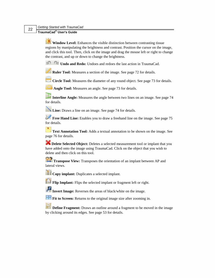
Window Level: Enhances the visible distinction between contrasting tissue
regions by manipulating the brightness and contrast. Position the cursor on the image,
and click this tool. Then, click on the image and drag the mouse left or right to change
the contrast, and up or down to change the brightness.
Undo and Redo: Undoes and redoes the last action in TraumaCad.
Ruler Tool: Measures a section of the image. See page 72 for details.
Circle Tool: Measures the diameter of any round object. See page 73 for details.
Angle Tool: Measures an angle. See page 73 for details.
Interline Angle: Measures the angle between two lines on an image. See page 74
for details.
Line: Draws a line on an image. See page 74 for details.
Free Hand Line: Enables you to draw a freehand line on the image. See page 75
for details.
Text Annotation Tool: Adds a textual annotation to be shown on the image. See
page 76 for details.
Delete Selected Object: Deletes a selected measurement tool or implant that you
have added onto the image using TraumaCad. Click on the object that you wish to
delete and then click on this tool.
Transpose View: Transposes the orientation of an implant between AP and
lateral views.
Copy implant: Duplicates a selected implant.
Flip Implant: Flips the selected implant or fragment left or right.
Invert Image: Reverses the areas of black/white on the image.
Fit to Screen: Returns to the original image size after zooming in.
Define Fragment: Draws an outline around a fragment to be moved in the image
by clicking around its edges. See page 53 for details.

Getting Started with TraumaCad
TraumaCad® User's Guide
23
Duplicate Fragment: Duplicates a fragment you cut out onto the current image
or onto another image. You may decide to duplicate a fragment and then flip it in
order to compare a fragment from one limb to another limb.
Help Mode: Displays the online help of this User Guide.
TraumaCad Right-click Menus
The right-click menus that display in TraumaCad vary, depending on the type of
object selected. The following figures show examples of the menus that display when
selecting measurements, fragments and templates, respectively.
Measurements Right-click Menu Templates Right-click Menu
The tools available in these menus are described on pages 15 and 19.
NOTE:
The Color option is available on the templates and measurements right-click menus. This
option enables you to change the color of the template/measurement tool on the screen.
Select this option to open a window in which you select the desired color for the
template/measurement tool.

Getting Started with TraumaCad
TraumaCad® User's Guide
24
Grouping Objects
TraumaCad enables you to group various types of objects together into a group,
including measurements, fragments and templates. Once grouped, the objects
comprising the group can be moved and rotated as a single object.
TraumaCad also provides special options for grouping templates. See page 57 for
more details.
► To group TraumaCad objects:
1 Using your mouse, hold down the mouse button and draw a selection box around
the objects to be grouped. A yellow bounding box surrounds the objects you
selected. Alternatively, you can select multiple objects while holding down the
Shift key.
2 Right-click on one of the objects within the bounding box and select Group. The
objects are now grouped and can be moved and rotated as a single object. To
rotate the group, click on the handle at the top of the bounding box and pull in the
direction in which you want to rotate the group.
Grouped items remain grouped until you ungroup them by using the right-click
menu or the Image menu.
Handle
Group Bounding Box

Preparing the Image
TraumaCad® User's Guide
25
4Chapter 2
Preparing the Image
NOTE:
Procedures and sections in the guide are marked to indicate whether they apply to
standalone mode ( ) or web client mode ( ).
TraumaCad supports DICOM and enables you to import (and export) any PACS file
(X-ray, CT or MR) from a central PACS system, a CD or from a local workstation.
JPG, scanner or digital camera images can also be imported, and any image can be
captured from the screen and used in TraumaCad. TraumaCad then provides an
automatic feature to ensure accurate calibration to bone size.
After an image has been prepared in TraumaCad, you can start the required surgical
planning procedure. See page 39 for details.
Step 1: Displaying the Image
If TraumaCad is integrated into your PACS, then all you need to do to access an
image is to display it in the PACS, and then select the TraumaCad option.
The following options are provided for importing images:
Loading Images from a PACS, page 26
Importing Images from a CD, page 181
Capturing Images from the Screen, page 182
Step 2: Specifying Anatomical Orientation
This step must be performed on all the images with which you want to work in
TraumaCad. See page 30 for details.
Step 3: Calibrating the Image
This step may be performed on images with which you want to work in TraumaCad.
See page 31 for details.

Preparing the Image
TraumaCad® User's Guide
26
Loading Images from a PACS
Finding the Patient
TraumaCad is transparently integrated with the PACS system and enables full access
to its patient images and information. TraumaCad provides a variety of options for
finding a specific patient of interest. After you have found the patient, you can select
the images in which you are interested.
► To find patient, perform any one of the following:
When working in web client mode, the window automatically shows the selected
patient row and the image(s) for this patient as a thumbnail(s).
When working in standalone mode, follow the steps below to find a patient.
Typically, this list is sorted by Last Name, then First Name and then Study Date.
2. Sort the list by clicking on the required attribute.
3. Select the patient of interest by clicking on the required row.
1. Click the Query button.
Preparing the Image
TraumaCad® User's Guide
27
You can scroll down in this list or sort the listed patients by clicking on the
dropdown arrow for a column (at the top of the list), and then selecting the sort
criterion to be used. You can perform any of the following options:
Select the From and/or To checkboxes and specify the range of dates of
interest. Click to see all the images within this date range.
Enter/select all or some of the patient’s information in the Patient ID,
Patient Name, Accession and Modality fields and click . You
can also enter part of the patient’s ID or name.
Select the Today, Yesterday, Last 7 Days, Last 14 Days or Last 30 Days
option and then click to see all the images within this date range.
Click to clear the fields previously entered.
NOTE:
Select File Delete Cache to clear the cache of images on your local
computer.
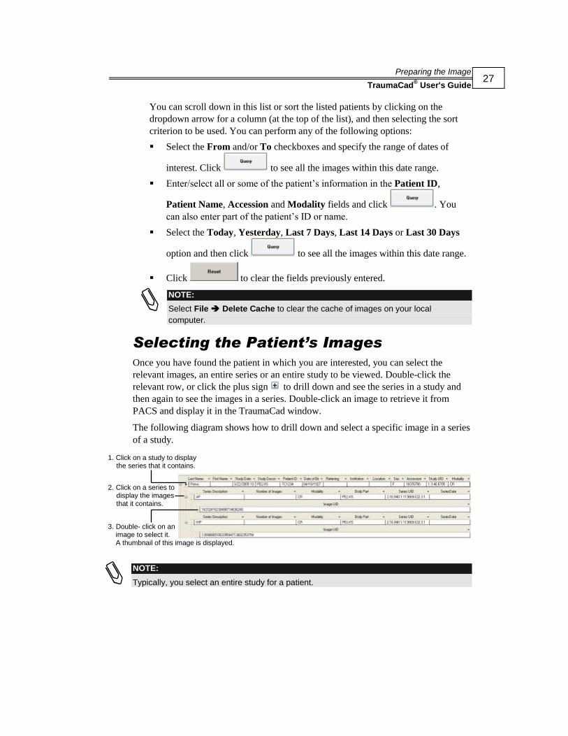
Selecting the Patient’s Images
Once you have found the patient in which you are interested, you can select the
relevant images, an entire series or an entire study to be viewed. Double-click the
relevant row, or click the plus sign to drill down and see the series in a study and
then again to see the images in a series. Double-click an image to retrieve it from
PACS and display it in the TraumaCad window.
The following diagram shows how to drill down and select a specific image in a series
of a study.
NOTE:
Typically, you select an entire study for a patient.
1. Click on a study to display the series that it contains.
2. Click on a series to display the images that it contains.
3. Double- click on an image to select it. A thumbnail of this image is displayed.

Preparing the Image
TraumaCad® User's Guide
28
Compressing Images
When working in client/server mode, you can compress images when retrieving them
for their faster retrieval time. By default, images are not compressed when working in
this mode.
NOTE:
Compression is disabled and cannot be performed when working in TraumaCad
standalone mode.
When you want to compress an image, you must specify both the type of compression
to be performed and the image quality factor to be used when importing the image.
The latter is designated by moving the Selected Compression slider to the required
position in a range from 1 to 100, where 1 represents the lowest image quality and 100
represents the maximum image quality. You specify the type of compression by
selecting the appropriate value in the Selected Compression dropdown list, as
follows:
Not selected: Images are not compressed during their retrieval. This is the default.
JPEG Lossy
JPEG 2000 Lossy
JPEG Lossless
JPEG 2000 Lossless

Preparing the Image
TraumaCad® User's Guide
29
The image is retrieved from the PACS according to the compression chosen.
The type of compression used is indicated at the bottom-left of the image.
NOTE:
In some cases, compression cannot be performed, such as when working with 16-bit
images. If you specify to compress an image, but the compression process fails, the image
is retrieved without compression being applied.

Preparing the Image
TraumaCad® User's Guide
30
Specifying Anatomical Orientation
After the images in which you are interested have been loaded from the PACS or
imported from a CD or your local computer, each of them are displayed in the sidebar
on the left of the window. Two examples are shown below, including a Lateral image
(top image) and an AP image (bottom image). Select the AP or LAT and Left or
Right radio buttons to indicate the anatomical orientation of an image and then click
. The Image Calibration window is then automatically displayed.
You can scroll up and down among the images that you have selected, if you have
selected more than two, and you can minimize the images of a specific series by
clicking .
Example 1: Lateral image
Example 2: AP image
Preparing the Image
TraumaCad® User's Guide
31
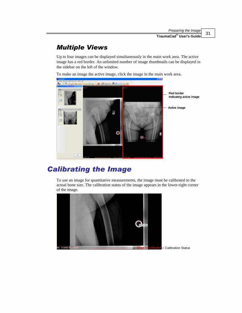
Multiple Views
Up to four images can be displayed simultaneously in the main work area. The active
image has a red border. An unlimited number of image thumbnails can be displayed in
the sidebar on the left of the window.
To make an image the active image, click the image in the main work area.
Active image
Red border
Indicating active image
Active image
Red border
Indicating active image
Calibrating the Image
To use an image for quantitative measurements, the image must be calibrated to the
actual bone size. The calibration status of the image appears in the lower-right corner
of the image.
Calibration Status
Preparing the Image
TraumaCad® User's Guide
32
One of the most beneficial features of TraumaCad is its ability to automatically
calibrate an image to the actual bone size by calibrating the image to a marker that is
imaged with the patient.
There are two options for calibrating an image:
Automatically, using either an OrthoMark device or a known-size ball marker.
For either of these methods, once you open the image, its calibration is detected
automatically. In this case, click Accept to accept the calibration.
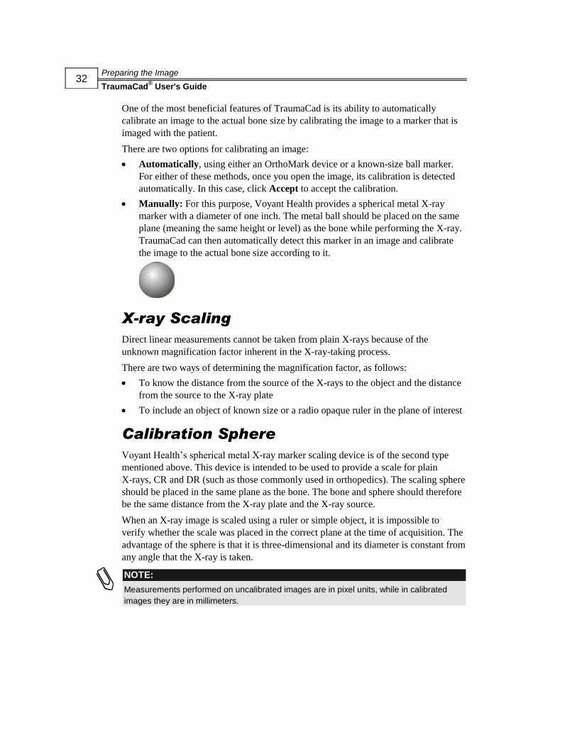
Manually: For this purpose, Voyant Health provides a spherical metal X-ray
marker with a diameter of one inch. The metal ball should be placed on the same
plane (meaning the same height or level) as the bone while performing the X-ray.
TraumaCad can then automatically detect this marker in an image and calibrate
the image to the actual bone size according to it.
X-ray Scaling
Direct linear measurements cannot be taken from plain X-rays because of the
unknown magnification factor inherent in the X-ray-taking process.
There are two ways of determining the magnification factor, as follows:
To know the distance from the source of the X-rays to the object and the distance
from the source to the X-ray plate
To include an object of known size or a radio opaque ruler in the plane of interest
Calibration Sphere
Voyant Health’s spherical metal X-ray marker scaling device is of the second type
mentioned above. This device is intended to be used to provide a scale for plain
X-rays, CR and DR (such as those commonly used in orthopedics). The scaling sphere
should be placed in the same plane as the bone. The bone and sphere should therefore
be the same distance from the X-ray plate and the X-ray source.
When an X-ray image is scaled using a ruler or simple object, it is impossible to
verify whether the scale was placed in the correct plane at the time of acquisition. The
advantage of the sphere is that it is three-dimensional and its diameter is constant from
any angle that the X-ray is taken.
NOTE:
Measurements performed on uncalibrated images are in pixel units, while in calibrated
images they are in millimeters.

Preparing the Image
TraumaCad® User's Guide
33
OrthoMark
The OrthoMark Reference marker is an exact 25.4 mm or 1 inch. The marker should
be positioned at bone level at the same distance from the detector plate (film plane),
whether it be CR or DR. The following two figures illustrate the positioning process.
With the marker at the same distance as the bone, the size is automatically calculated
by the software used for choosing prosthetic sizes.
TIP:
For automatic calibration to be enabled, you must use Orthomark . Contact your
Voyant Health sales representative if you need to obtain it.

Preparing the Image
TraumaCad® User's Guide
34
Calibration Window
When you access an image, it opens initially with an Image Calibration window,
which provides various options for calibrating the image. After calibration is
completed, as described in this section, click or
and proceed to Chapter 3, TraumaCad Pre-operative
Procedures on page 39.
The Image Calibration window appears as follows, depending on whether the
spherical metal X-ray marker is found or not:
Found Not Found
The following describes what happens when the marker is found. If no marker is
detected, then refer to the Calibrating the Image section on page 31 for instructions.
If the marker is found, the message Metal Ball found where shown is displayed and
the following appears on the marker in the image:
Click to accept this calibration.

Preparing the Image
TraumaCad® User's Guide
35
The selected image is then displayed in the work area, as shown below:
NOTE:
If the Remove Marker after calibration option is checked in the Calibration window, then
the meaurements on the marker are removed after calibration and the marker appears as it
was before calibration, for example, as follows:
Now, click and proceed to Chapter 3, TraumaCad Pre-operative
Procedures on page 39.
Even if the metal ball is found, you may decide to manually or semi-automatically
calibrate the image, as described on page 36.
If you decide not to calibrate the image, then click and proceed
to Chapter 3, TraumaCad Pre-operative Procedures on page 39.
The following describes the various options for calibrating an image.
Preparing the Image
TraumaCad® User's Guide
36
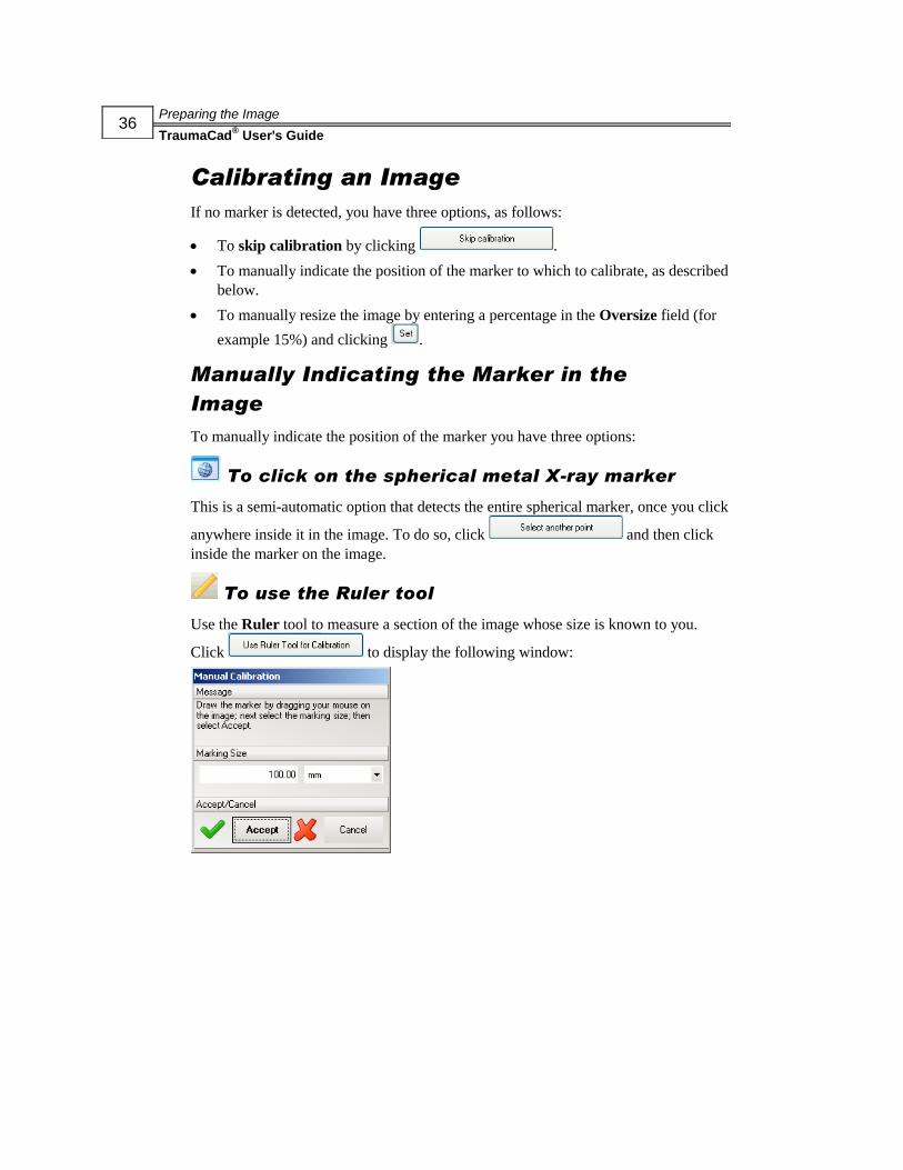
Calibrating an Image
If no marker is detected, you have three options, as follows:
To skip calibration by clicking .
To manually indicate the position of the marker to which to calibrate, as described
below.
To manually resize the image by entering a percentage in the Oversize field (for
example 15%) and clicking .
Manually Indicating the Marker in the
Image
To manually indicate the position of the marker you have three options:
To click on the spherical metal X-ray marker
This is a semi-automatic option that detects the entire spherical marker, once you click
anywhere inside it in the image. To do so, click and then click
inside the marker on the image.
To use the Ruler tool
Use the Ruler tool to measure a section of the image whose size is known to you.
Click to display the following window:

Preparing the Image
TraumaCad® User's Guide
37
Draw a line to indicate the size of the marker in the image. The size of the line is
displayed on the image and changes as you draw and resize the line:
The size of the line is also shown in the Marking Size field. If you know that the
marker’s actual size is 100 mm, then make sure that the Marking Size field shows
that value. You can manually change it to adjust the size of the line in the image.
When the line exactly covers the extent of the marker in the image, click .
To use the Circle tool
Click to display the following window:

Preparing the Image
TraumaCad® User's Guide
38
Click on the marker in the image. A circle marker is automatically drawn:
Drag this circle to exactly cover the marker.
You can resize the circle by manually changing the value in the Marking Size field. If
you know that the marker’s actual size is one inch, then make sure that the Marking
Size field shows that value.
You can also easily set the size of the circle to exactly cover the marker’s image, by
manually positioning (dragging) each of the three anchors (red plus signs) of the circle
onto the outer rim of the marker’s image.
The diameter of the circle is displayed on the image and changes as you draw and
resize the circle. When the circle exactly covers the extent of the marker in the image,
click .
Copying the Calibration
The Copy Calibration feature enables you to copy calibration data from one series to
another within the same study. This feature is useful when a study includes multiple
series of images.
► To copy calibration data between series within a study:
1 Open the first series of images within a study.
2 Open the next series of images within the same study to which you want to apply
the calibration settings from the first series.
3 Click the Copy Calibration button.
NOTE:
You should not use the Copy Calibration feature to copy calibration data between
studies.
Drag this anchor to the outer rim of the Marker’s image here.
TraumaCad Pre-operative Procedures
TraumaCad® User's Guide
39
5Chapter 3
TraumaCad Pre-operative
Procedures
NOTE:
Procedures and sections in the guide are marked to indicate whether they apply to
standalone mode ( ) or web client mode ( ).
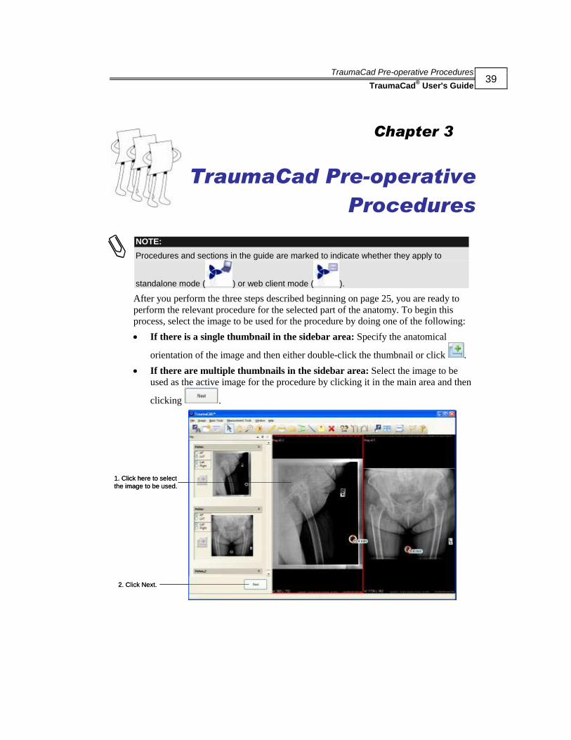
After you perform the three steps described beginning on page 25, you are ready to
perform the relevant procedure for the selected part of the anatomy. To begin this
process, select the image to be used for the procedure by doing one of the following:
If there is a single thumbnail in the sidebar area: Specify the anatomical
orientation of the image and then either double-click the thumbnail or click .
If there are multiple thumbnails in the sidebar area: Select the image to be
used as the active image for the procedure by clicking it in the main area and then
clicking .
1. Click here to select
the image to be used.
2. Click Next.
1. Click here to select
the image to be used.
2. Click Next.

TraumaCad Pre-operative Procedures
TraumaCad® User's Guide
40
Both of these actions open a window such as the one below:
This window consists of a series of tabs on the left and the main area on the right that
displays an image(s).
The following tabs are shown in this window:
Templates: Identifies the required implant. For some of procedures, this tab
displays by default. See page 42 for more details. Four sub-tabs are displayed
under the Templates tab, as follows:
Implants: Specifies the implant product family for templates of a given type
by a specific manufacturer. See page 44 for details.
Kits: Enables you to define your own kits of templates that you can add to
an image together. See page 42 for details.
Recently Used: Lists the last 20 templates used in this procedure.
Favorites: Saves templates to a favorites list, thereby providing quick access
to them.

TraumaCad Pre-operative Procedures
TraumaCad® User's Guide
41
Measurement Tools: Measures the actual anatomy in the image using a variety
of tools provided by TraumaCad. For more information, refer to Chapter 4,
Measuring the Anatomy on page 71.
NOTE:
All measurement wizards contain an Undo button, which enables you to
cancel your last action and return to the previous step in the wizard. This button is
only available in TraumaCad measurement wizards that have multiple steps.
All measurement wizards also contain the Back To Measurements List
button, which enables you to exit the wizard and return to the list of
measurement tools.
Report: Creates a report containing textual information describing the patient, the
measurements, the surgical procedure to be performed and/or the implant to be
used and any text that the surgeon chooses to add. See page 169 for more details.
TraumaCad Pre-operative Procedures
TraumaCad® User's Guide
42
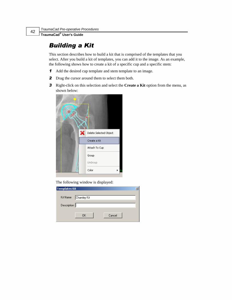
Building a Kit
This section describes how to build a kit that is comprised of the templates that you
select. After you build a kit of templates, you can add it to the image. As an example,
the following shows how to create a kit of a specific cup and a specific stem:
1 Add the desired cup template and stem template to an image.
2 Drag the cursor around them to select them both.
3 Right-click on this selection and select the Create a Kit option from the menu, as
shown below:
The following window is displayed:
TraumaCad Pre-operative Procedures
TraumaCad® User's Guide
43
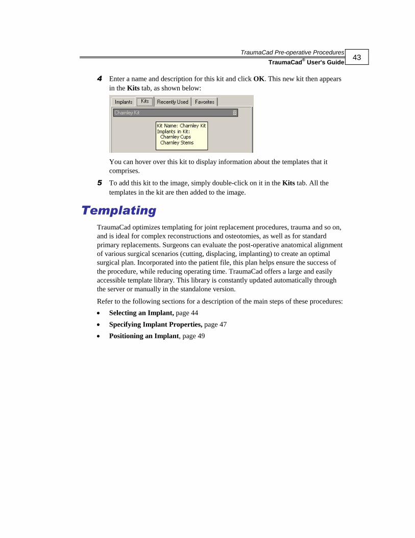
4 Enter a name and description for this kit and click OK. This new kit then appears
in the Kits tab, as shown below:
You can hover over this kit to display information about the templates that it
comprises.
5 To add this kit to the image, simply double-click on it in the Kits tab. All the
templates in the kit are then added to the image.
Templating
TraumaCad optimizes templating for joint replacement procedures, trauma and so on,
and is ideal for complex reconstructions and osteotomies, as well as for standard
primary replacements. Surgeons can evaluate the post-operative anatomical alignment
of various surgical scenarios (cutting, displacing, implanting) to create an optimal
surgical plan. Incorporated into the patient file, this plan helps ensure the success of
the procedure, while reducing operating time. TraumaCad offers a large and easily
accessible template library. This library is constantly updated automatically through
the server or manually in the standalone version.
Refer to the following sections for a description of the main steps of these procedures:
Selecting an Implant, page 44
Specifying Implant Properties, page 47
Positioning an Implant, page 49

TraumaCad Pre-operative Procedures
TraumaCad® User's Guide
44
Selecting an Implant
The process of using TraumaCad for each of the procedures (hip, knee, trauma, spine,
foot and ankle, and upper limb) is similar. Of course, the implant library differs for
different anatomical regions. A window such as the following is shown when you
select templates:
At this point you may want to use any of the variety of measurement tools provided
by TraumaCad to measure the anatomical region of the patient, as described in
Chapter 4, Measuring the Anatomy on page 71.
The process of identifying the required implant is also referred to as Templating.
During this process, you first select the appropriate implant according to the available
inventory, size and a variety of other properties. You then position it on the image on
the appropriate anatomy.
TraumaCad Pre-operative Procedures
TraumaCad® User's Guide
45
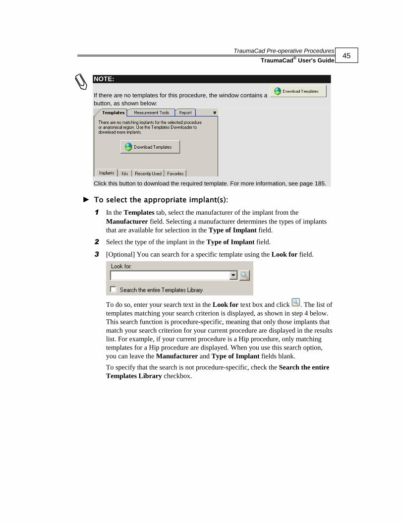
NOTE:
If there are no templates for this procedure, the window contains a
button, as shown below:
Click this button to download the required template. For more information, see page 185.
► To select the appropriate implant(s):
1 In the Templates tab, select the manufacturer of the implant from the
Manufacturer field. Selecting a manufacturer determines the types of implants
that are available for selection in the Type of Implant field.
2 Select the type of the implant in the Type of Implant field.
3 [Optional] You can search for a specific template using the Look for field.
To do so, enter your search text in the Look for text box and click . The list of
templates matching your search criterion is displayed, as shown in step 4 below.
This search function is procedure-specific, meaning that only those implants that
match your search criterion for your current procedure are displayed in the results
list. For example, if your current procedure is a Hip procedure, only matching
templates for a Hip procedure are displayed. When you use this search option,
you can leave the Manufacturer and Type of Implant fields blank.
To specify that the search is not procedure-specific, check the Search the entire
Templates Library checkbox.

TraumaCad Pre-operative Procedures
TraumaCad® User's Guide
46
Click the Look for dropdown arrow to display a history of past searches. You
can select an item in the dropdown list, as appropriate.
4 Select the implant product family in the Implants list. Many implant products
may be available for selection. Scroll right or left using the scroll bar under this
list to see them all.
5 Click on the arrow next to the implant product to see a preview image of the
implant:
► To save an implant in the Favorites tab:
Select the implant product family in the Implants list. While holding down the
mouse button, drag and drop the implant onto the Favorites tab. You can also add
implants to the Favorites tab from the Recently Used tab. Simply select the
required implant in this tab and drag and drop it onto the Favorites tab.
Click here to see preview

TraumaCad Pre-operative Procedures
TraumaCad® User's Guide
47
Specifying Implant Properties
Once you have selected the required implant, you can position it on the image and
specify more properties of the implant to suit the surgical procedure, such as its size,
offset and number of attachments. You may require more than a single implant for a
specific surgical procedure.
► To specify implant properties:
1 Double-click on the implant’s name in the Implants list on the left. This places
the implant in the center of the image.
Or
Drag the implant from the list on the left onto the image.
A selection of properties appears on the left, as shown above.
NOTE:
You can click the yellow rectangle surrounding the implant and then drag and drop to
move the implant on the image.
Properties
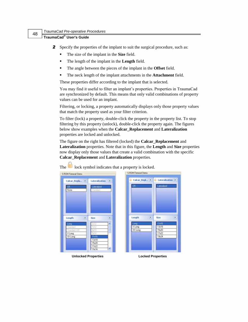
TraumaCad Pre-operative Procedures
TraumaCad® User's Guide
48
2 Specify the properties of the implant to suit the surgical procedure, such as:
The size of the implant in the Size field.
The length of the implant in the Length field.
The angle between the pieces of the implant in the Offset field.
The neck length of the implant attachments in the Attachment field.
These properties differ according to the implant that is selected.
You may find it useful to filter an implant’s properties. Properties in TraumaCad
are synchronized by default. This means that only valid combinations of property
values can be used for an implant.
Filtering, or locking, a property automatically displays only those property values
that match the property used as your filter criterion.
To filter (lock) a property, double-click the property in the property list. To stop
filtering by this property (unlock), double-click the property again. The figures
below show examples when the Calcar_Replacement and Lateralization
properties are locked and unlocked.
The figure on the right has filtered (locked) the Calcar_Replacement and
Lateralization properties. Note that in this figure, the Length and Size properties
now display only those values that create a valid combination with the specific
Calcar_Replacement and Lateralization properties.
The lock symbol indicates that a property is locked.
Unlocked Properties Locked Properties

TraumaCad Pre-operative Procedures
TraumaCad® User's Guide
49
3 While selecting the appropriate implant for total hip replacement, take note of the
projected post-operative parameters Offset changes and Leg length changes on
the bottom-left of the window. If both a stem and a cup implant are placed on the
image, these indicate the anatomical changes that will occur as a result of the
procedure.
4 If at any point you want to place another implant on the image, click
.
5 If at any point you want to delete the selected implant from the image, simply
select it and press the Delete key or the Delete Selected Object tool.
Positioning an Implant
You should position the implant on the image according to surgical considerations. A
number of options are provided to facilitate implant positioning on the image.
► To move an implant:
Make sure that the Move tool is selected, and then click on the implant and
drag it to the required position. You can use the arrow keys to move the implant
in small increments.
► To rotate an implant:
The selected implant is indicated by its light (highlighted color) and a rotation
handle:
Hinge
Rotation Handle
Drag the rotation handle to the left, right, up or down to pivot the implant around
its hinge.

TraumaCad Pre-operative Procedures
TraumaCad® User's Guide
50
You can also flip an implant using the Flip Implant tool, and change it from
AP to LAT and vice versa by using the Transpose View tool.
The selected implant automatically appears in the new orientation. You should
position it on the image.
Trauma Procedures
TraumaCad is designed to meet the needs of the trauma environment. TraumaCad
enables you to define fracture or bone fragments, and to move, rotate and copy
fragments on the image to reconstruct on the healthy side and accurately restore the
anatomy on images prior to templating.
Specifying the Anatomical Region (for a trauma procedure), page 51.
Defining and Reducing the Bone Fragments, page 53. You may try different
options for reducing the fragments and then select the optimal one.
Special Trauma Template Features, page 56. Some TraumaCad trauma
templates have special features not available with other templates, such as the
ability to bend plate templates at marked points and determine screw type
properties.

TraumaCad Pre-operative Procedures
TraumaCad® User's Guide
51
Specifying the Anatomical Region
After you select , the following window is displayed, in which you specify
the anatomical region for the procedure:

TraumaCad Pre-operative Procedures
TraumaCad® User's Guide
52
► To specifying an anatomical region of the body:
1 Move the mouse over each relevant area of the body on the skeletal image on the
left. As you do so, it is highlighted in red. This action filters out templates that do
not apply.
NOTE:
Click the Skip Anatomical Region Selection button to disable template filtering.
2 Click on the relevant part of the body to open a window such as the one shown on
page 40, which provides access to Templates, Measurement Tools and Reports.
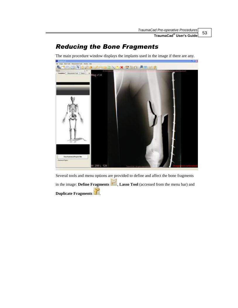
TraumaCad Pre-operative Procedures
TraumaCad® User's Guide
53
Reducing the Bone Fragments
The main procedure window displays the implants used in the image if there are any.
Several tools and menu options are provided to define and affect the bone fragments
in the image: Define Fragments , Lasso Tool (accessed from the menu bar) and
Duplicate Fragments .

TraumaCad Pre-operative Procedures
TraumaCad® User's Guide
54
Defining Fragments
► To define fragments:
1 Select the Define Fragments tool in the toolbar or select Basic Tools
Fragments Define Fragment in the menu bar. Make a series of clicks along
the outline of the fragment to be moved.
2 Close the outline drawing of the fragment by double-clicking. You now have a
closed shape that you can drag to a new position:
Pivot Point
Selection Box

TraumaCad Pre-operative Procedures
TraumaCad® User's Guide
55
You can now reposition or adjust the selection of the fragment as required using
any of the following options:
Press the Delete key to delete the selected outline.
The dot in the center of the fragment that you have traced is the pivot point. If
you drag the handle, the fragment rotates around it. You can also drag this
pivot point to a new position and then rotate the fragment by dragging its
handle.
You can flip this fragment using the Flip Implant tool.
You can duplicate this fragment using the Duplicate Fragment tool.
You can copy the fragment by selecting Image Copy to Clipboard in the
menu bar. To paste the fragment, simply click on the image and press Ctrl+V
on your keyboard.
Delete the fragment using the Delete Selected Object tool.
Return a manipulated fragment to its original location by clicking and
deleting it, and then clicking on its original location and clicking Delete
again.
Send the fragment forward or backward on the image by selecting Basic
Tools Fragments Fragment Bring to Front or Basic Tools
Fragments Fragment Send to Back in the menu bar, respectively.
Lasso Fragments
Lassoing fragments means to simply draw a line around the area of the image that
contains the fragments to be moved.
► To lasso fragments:
1 Select Basic Tools Fragments Lasso Tool in the menu bar.
2 Click and hold down the mouse button and drag the mouse around the area to be
moved. A line will be drawn as you move the mouse:

TraumaCad Pre-operative Procedures
TraumaCad® User's Guide
56
3 After the fracture is reduced, you can add implants for fixation. For details
describing how to perform this procedure, refer to the sections listed below:
Selecting an Implant, page 44
Specifying Implant Properties, page 47
Positioning an Implant, page 49
Special Trauma Template Features
Some TraumaCad trauma templates have special features not available to other
templates, including:
Plate bending capabilities, below
Grouping capabilities, page 57
Handling of screws in Locking Compression Plates, page 59
Plate Bending
Some plates used in trauma procedures can be bent to better conform to the curvature
of the bone. Such plates display a series of red points on the template on the image.
The plate can be bent at each of these points, as needed.
For example, the figures below show examples of such a plate before and after
bending:
Before Bending After Bending
► To bend a plate template:
Click on a red point on the plate template on the image, and while holding down
the mouse button, pull to bend the plate to the required position. Repeat for other
points on the plate, as needed.

TraumaCad Pre-operative Procedures
TraumaCad® User's Guide
57
Grouping Templates
Some templates in the TraumaCad system are grouped by default. For such grouped
templates, the items contained with the group are surrounded by a yellow box, which
indicates the boundaries of the group. This box contains a handle at the top, which can
be used to move or rotate the entire group on the image.
For example, the figures below show a grouped template that contains both a plate
and screws. For a grouped template, you can manipulate the properties of each
element within the group individually. The figures below show the same template
before and after resizing the plate. Note that the plate has been elongated in the figure
on the right during resizing.
Plate Before Resizing Plate After Resizing
You can select any item within a grouped template. The selected item is highlighted in
dark green. You can only change the size of an item when it is highlighted.
All items comprising a grouped template can be moved and rotated together as a
single group using the yellow handle at the top of the group.
You can also add multiple templates to an image and then group them to create a
single group.
Grouped Items
Handle
Selected Item

TraumaCad Pre-operative Procedures
TraumaCad® User's Guide
58
► To create a template group:
1 Add two or more templates to an image.
2 Click on one of the templates to select it, and while holding down the Shift key,
click on another template to select it. You can add an unlimited number of items
to a single template group.
3 Right-click on one of the templates you selected and select Group. The templates
are now grouped. Grouped items remain grouped until you physically ungroup
them. In the example below, two templates – a head template and a stem template
– have been grouped. Note that the yellow bounding box completely surrounds
both templates, indicating that both are part of a single group.
NOTES:
Templates grouped in this fashion are only grouped in this image, and not within the
TraumaCad template library.
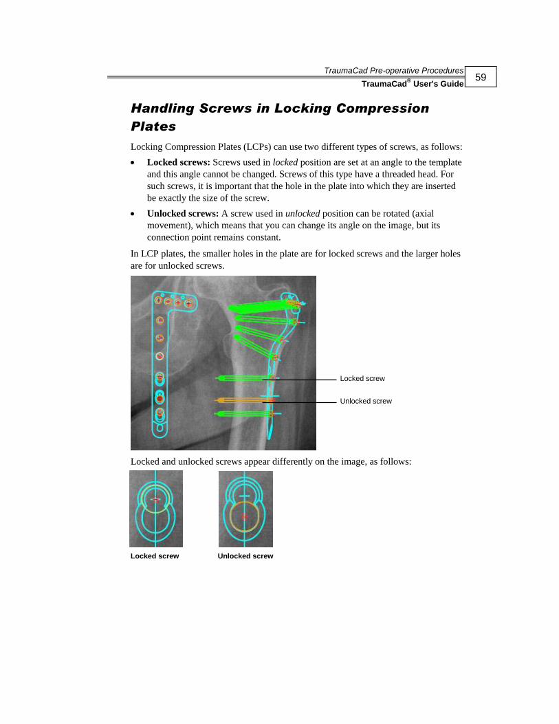
TraumaCad Pre-operative Procedures
TraumaCad® User's Guide
59
Handling Screws in Locking Compression
Plates
Locking Compression Plates (LCPs) can use two different types of screws, as follows:
Locked screws: Screws used in locked position are set at an angle to the template
and this angle cannot be changed. Screws of this type have a threaded head. For
such screws, it is important that the hole in the plate into which they are inserted
be exactly the size of the screw.
Unlocked screws: A screw used in unlocked position can be rotated (axial
movement), which means that you can change its angle on the image, but its
connection point remains constant.
In LCP plates, the smaller holes in the plate are for locked screws and the larger holes
are for unlocked screws.
Locked and unlocked screws appear differently on the image, as follows:
Locked screw Unlocked screw
Unlocked screw
Locked screw

TraumaCad Pre-operative Procedures
TraumaCad® User's Guide
60
In LCP templates, several options are available for handling the screws within the
template. You can:
Lock a screw.
Unlock a screw.
Remove a screw.
Remove all screws.
To use one of these options, simply right-click a screw in the template and select the
relevant option in the right-click menu.
If you remove a screw from a template, you can reattach it by right-clicking the hole
where the screw should be affixed and selecting Re-attach Screw in the right-click
menu.

TraumaCad Pre-operative Procedures
TraumaCad® User's Guide
61
3D Suite (Optional)
The TraumaCad 3D module enables you to view images, such as CTs and MRIs, in
three dimensions using Multi-Planar Reconstruction (MPR) or Maximum Intensity
Projection (MIP). The images are shown in Axial, Coronal, Sagittal and Oblique
views. In addition, the user can add three-dimensional templates to the image in order
to do preoperative planning.
This section describes how to use the optional 3D module in TraumaCad.

TraumaCad Pre-operative Procedures
TraumaCad® User's Guide
62
Opening a 3D Image
Select the 3D procedure in the Procedure Selection window (shown on the previous
page).
Click on a CT or MR study in the patient list. The included series are opened in the
thumbnail view.
Choose Left or Right and then click on the plus sign to open the series in the
main view.
NOTE:
Only series in Axial orientation can be displayed in 3D mode.
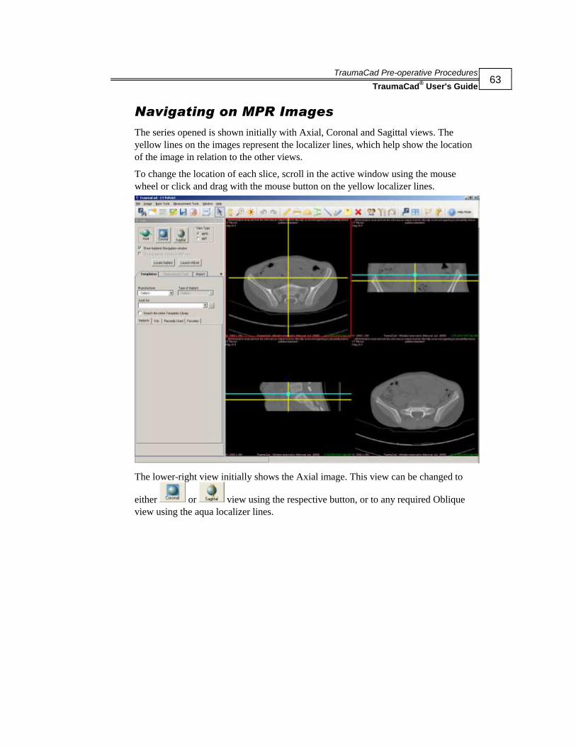
TraumaCad Pre-operative Procedures
TraumaCad® User's Guide
63
Navigating on MPR Images
The series opened is shown initially with Axial, Coronal and Sagittal views. The
yellow lines on the images represent the localizer lines, which help show the location
of the image in relation to the other views.
To change the location of each slice, scroll in the active window using the mouse
wheel or click and drag with the mouse button on the yellow localizer lines.
The lower-right view initially shows the Axial image. This view can be changed to
either or view using the respective button, or to any required Oblique
view using the aqua localizer lines.

TraumaCad Pre-operative Procedures
TraumaCad® User's Guide
64
To change the orientation of this view, click on the red holding points and rotate the
aqua localizer line to the preferred Oblique view.
NOTE:
The orientation chosen to be shown in the lower-right view has its aqua localizer lines
shown in the two orthogonal views.

TraumaCad Pre-operative Procedures
TraumaCad® User's Guide
65
Changing the View Type to MIP
To change the bottom-right image to an MIP view, select the MIP radio button.
The MIP view can be shown in Axial, Coronal or Sagittal orientations only.

TraumaCad Pre-operative Procedures
TraumaCad® User's Guide
66
Adding a 3D Template
The procedure for adding a 3D template to the image is identical to that for adding a
2D template. For more information, see page 43.
For MPR views, the outline of the template is shown according to the slice location
and orientation. For MIP views, the template is shown as a complete projection of the
implant. The implant can be shown in grayscale on the MIP view.
When the 3D suite option is available, the following two buttons appear, as shown
above:
Locate implant: Scrolls all the views to the implant location, meaning that this
button is shown in all the views.
Launch AQnet: Opens the 3D view inside the Terarecon viewer. This button is
only displayed when Terarecon Integration is defined.

TraumaCad Pre-operative Procedures
TraumaCad® User's Guide
67
The implant is also shown in a separate navigation window, in order to allow easier
orientation and rotation of the implant.
NOTE:
Moving or rotating the implant on one of the views affects its position and orientation on
all other views.
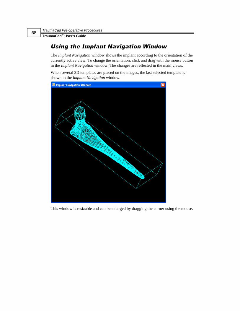
TraumaCad Pre-operative Procedures
TraumaCad® User's Guide
68
Using the Implant Navigation Window
The Implant Navigation window shows the implant according to the orientation of the
currently active view. To change the orientation, click and drag with the mouse button
in the Implant Navigation window. The changes are reflected in the main views.
When several 3D templates are placed on the images, the last selected template is
shown in the Implant Navigation window.
This window is resizable and can be enlarged by dragging the corner using the mouse.
TraumaCad Pre-operative Procedures
TraumaCad® User's Guide
69
Auto-Hip Procedure
Digital preplanning for hip replacement surgery is a common orthopedic surgery
procedure used to estimate implant size, determine the post-operative geometrical
relationship between the femur and the acetabulum, the resulting leg length and offset
change, and predict any geometrical mismatch and difficulty pre-operatively.
Auto-hip Procedure is a software module for the automatic marking of specific points
within an anterior-posterior pelvis X-ray image. The program then positions the
desired implant according to predefined orthopedic rules, thereby enabling fully
automatic hip preplanning.
A set of anatomic landmarks on a pelvic AP X-ray is defined in a way that determines
the size of the femoral stem and its expected stable position in the femoral canal.
Points of interest are the femur midline and diameter of its channel, greater
trochanters tips, lesser trochanters tips and bottom tangent line to the visible ischial
tuberoses curves.
For details describing how to perform this procedure, refer to the Auto-Hip
Measurements section on page 77.
Deformity Procedure
Preplanning for lower limb deformity correction surgery is the art of describing the
properties of the deformation and the means of its correction.
The user must draw a model assessing the transfer of load from the point of which it is
applied to the limb – usually at the center of the femoral head, through its geometrical
relations with the major joints and to the center of the ankle, where it is transferred to
the ground.
The purpose of defining the axes of load is to be able to define the centers of any
anatomic deformation along the pass of bony structures, calculate its magnitude and
suggest the best means of correction.
The outcome of the procedure is a plan describing where a bone should be cut and the
angle it needs to rotate around a chosen pivot, in order to re-establish the correct
length and axis for load transfer.
For details describing how to perform this procedure, refer to the Deformity
Meaaurements section on page 80.

TraumaCad Pre-operative Procedures
TraumaCad® User's Guide
70
This page is intentionally left blank.
Measuring the Anatomy
TraumaCad® User's Guide
71
6Chapter 4
Measuring the Anatomy
NOTE:
Procedures and sections in the guide are marked to indicate whether they apply to
standalone mode ( ) or web client mode ( ).
After you have calibrated the image you may want to measure the actual anatomy in
the image using a variety of tools provided by TraumaCad.
Most of TraumaCad’s measurement tools can be accessed from both the Measurement
Tools menu and from the Measurement Tools tab. The most frequently used tools
can also be accessed from the toolbar and by right-clicking on the image.
All tools are described in the sections that follow, and are organized by TraumaCad
procedure. They can be used digitally in the same manner that they are used for
physical measurements.
NOTES:
To obtain quantitative measurements, the image must first be calibrated, as described in
the Calibrating the Image section on page 31.
This chapter also describes the Growth Calculator on page 163, which predicts the
growth of a particular anatomy in pediatric orthopedics.
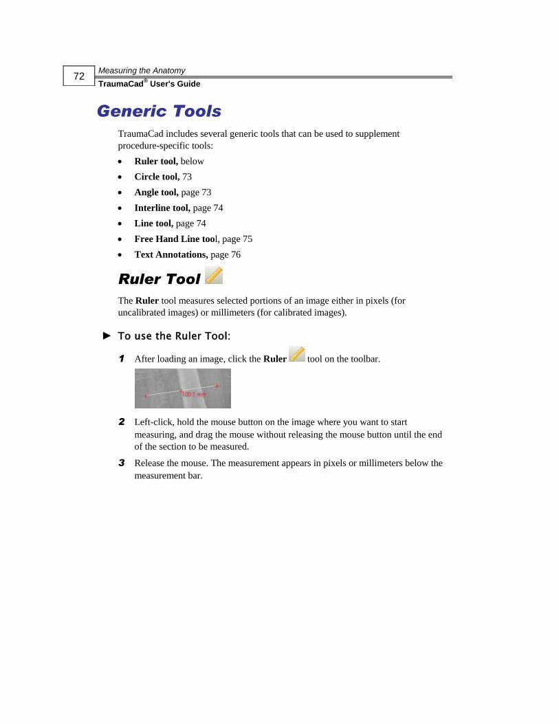
Measuring the Anatomy
TraumaCad® User's Guide
72
Generic Tools
TraumaCad includes several generic tools that can be used to supplement
procedure-specific tools:
Ruler tool, below
Circle tool, 73
Angle tool, page 73
Interline tool, page 74
Line tool, page 74
Free Hand Line tool, page 75
Text Annotations, page 76
Ruler Tool
The Ruler tool measures selected portions of an image either in pixels (for
uncalibrated images) or millimeters (for calibrated images).
► To use the Ruler Tool:
1 After loading an image, click the Ruler tool on the toolbar.
2 Left-click, hold the mouse button on the image where you want to start
measuring, and drag the mouse without releasing the mouse button until the end
of the section to be measured.
3 Release the mouse. The measurement appears in pixels or millimeters below the
measurement bar.

Measuring the Anatomy
TraumaCad® User's Guide
73
Circle Tool
Use the Circle tool to measure the diameter of objects in the image.
► To use the Circle Tool:
1 Click in the toolbar.
2 Click on the image in the work area. The Circle tool appears on the image.
3 Left-click and hold the mouse button inside the circle and drag it to the desired
position.
4 Click and drag on each of the three crosses in turn to adjust the size of the circle.
5 The diameter measurement (if calibrated in millimeters) appears in the lower-half
of the circle.
Angle Tool
The Angle tool measures the angle between two areas or lines.
► To use the Angle Tool:
1 Click in the toolbar.
2 Click on the image in the work area. The Angle tool is displayed.
3 Drag the edges of the tool to the edges of the sections to be measured. The
measurement appears in degrees next to the angle.
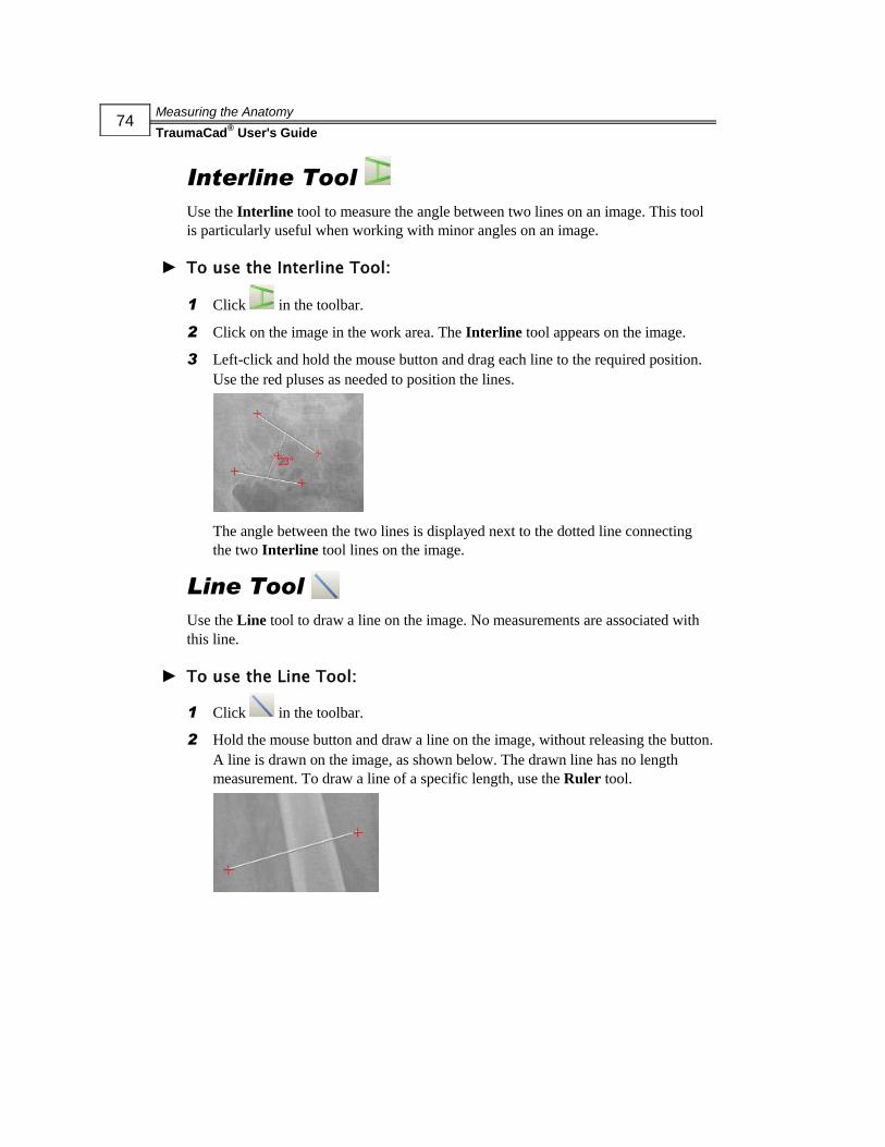
Measuring the Anatomy
TraumaCad® User's Guide
74
Interline Tool
Use the Interline tool to measure the angle between two lines on an image. This tool
is particularly useful when working with minor angles on an image.
► To use the Interline Tool:
1 Click in the toolbar.
2 Click on the image in the work area. The Interline tool appears on the image.
3 Left-click and hold the mouse button and drag each line to the required position.
Use the red pluses as needed to position the lines.
The angle between the two lines is displayed next to the dotted line connecting
the two Interline tool lines on the image.
Line Tool
Use the Line tool to draw a line on the image. No measurements are associated with
this line.
► To use the Line Tool:
1 Click in the toolbar.
2 Hold the mouse button and draw a line on the image, without releasing the button.
A line is drawn on the image, as shown below. The drawn line has no length
measurement. To draw a line of a specific length, use the Ruler tool.
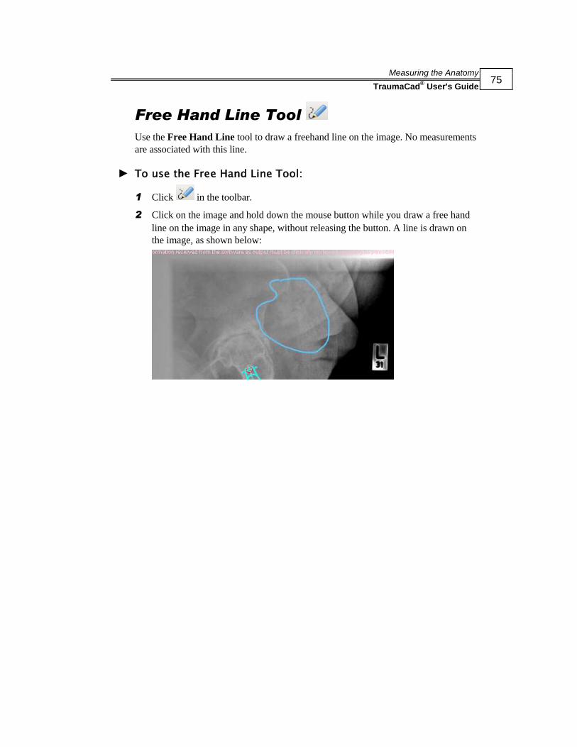
Measuring the Anatomy
TraumaCad® User's Guide
75
Free Hand Line Tool
Use the Free Hand Line tool to draw a freehand line on the image. No measurements
are associated with this line.
► To use the Free Hand Line Tool:
1 Click in the toolbar.
2 Click on the image and hold down the mouse button while you draw a free hand
line on the image in any shape, without releasing the button. A line is drawn on
the image, as shown below:

Measuring the Anatomy
TraumaCad® User's Guide
76
Text Annotations
Use the Text Annotations tool to add free text to the basic measurements. When text
is added to the image, a line shows the connection between the text and the part of the
image to which it applies. You can drag this text away if it is obstructing the view.
The line will lengthen and still point to the part of the image to which the text applies.
► To add text annotations to an image:
1 Click Text Annnotation in the toolbar and then click on the image.
Or
Double-click on a measurement in the image. The following window is displayed:
2 Enter your text in the text box.
3 Optionally, change the text color, font, anchor color and so on by clicking File
TraumaCad Settings Text and specifying the required setting.
4 Click OK to save your settings. All data is saved with the image on the PACS and
on reports.

Measuring the Anatomy
TraumaCad® User's Guide
77
Auto-Hip Measurements
► To use the Auto-Hip tool:
1 Select the Auto-Hip procedure .
2 In the Templates tab, select the relevant templates, which are then displayed in
the Implants tab, as shown below:

Measuring the Anatomy
TraumaCad® User's Guide
78
3 Drag and drop or double-click on a template in the Implants tab to add it to the
image. For example, as shown below:
This tool automatically places the stem in the femoral channel according to the
selected side (right or left). This tool also automatically defines an image
fragment that contains the femur. The Leg Length Discrepancy tool, described on
page 100, is also automatically added to the image.
4 Even though the tool automatically selects and places the stem, you may want to
fine tune its position by dragging the fragment or adjusting the size of the stem in
the Size field in the Implants tab.
5 Select the required cup template and cup size and add it to the image.
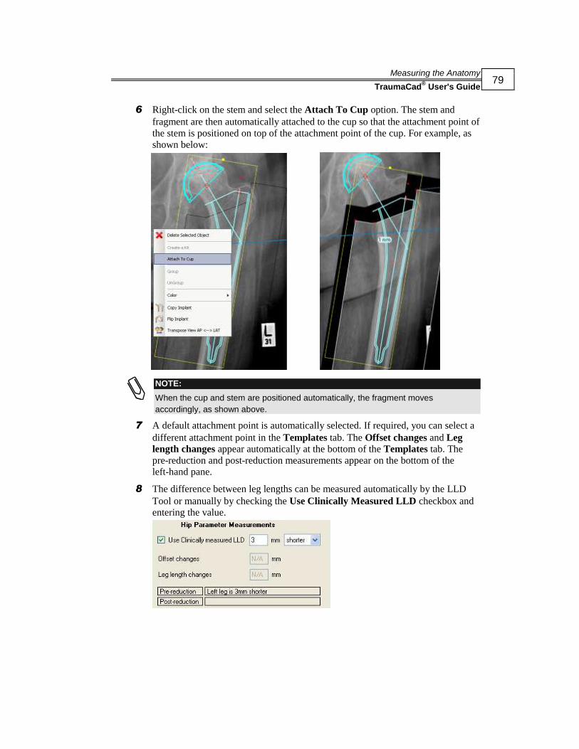
Measuring the Anatomy
TraumaCad® User's Guide
79
6 Right-click on the stem and select the Attach To Cup option. The stem and
fragment are then automatically attached to the cup so that the attachment point of
the stem is positioned on top of the attachment point of the cup. For example, as
shown below:
NOTE:
When the cup and stem are positioned automatically, the fragment moves
accordingly, as shown above.
7 A default attachment point is automatically selected. If required, you can select a
different attachment point in the Templates tab. The Offset changes and Leg
length changes appear automatically at the bottom of the Templates tab. The
pre-reduction and post-reduction measurements appear on the bottom of the
left-hand pane.
8 The difference between leg lengths can be measured automatically by the LLD
Tool or manually by checking the Use Clinically Measured LLD checkbox and
entering the value.
Measuring the Anatomy
TraumaCad® User's Guide
80
Deformity Measurements
Currently, there is only one automatic deformity measurement tool, which is called
Limb Alignment Analysis automatic deformity measurement, as described below.
Limb Alignment Analysis
The Limb Alignment Analysis tool enables orthopedic surgeons to measure and
display the anatomic and mechanic axes of deformed limbs. The common joint angles
are automatically calculated and compared to normative standards and are used to
simulate corrective procedures. The anatomical measurements can be unilateral or
bilateral. Measurements and evaluations can be integrated into patient files for an easy
transition to digital radiology.
► To perform limb alignment analysis:
1 Select the Limb Alignment Analysis option in the Measurement Tools tab.
2 Use the wizard to mark anatomical land marks on the image for limb alignment
analysis, as described below.
3 Use the CORA tools, as described on page 85.
4 You can simulate osteotomies and implant fixation, as described on page 109.
5 You have the option to use TraumaCad’s comprehensive Growth Calculator tool,
as described on page 163.

Measuring the Anatomy
TraumaCad® User's Guide
81
Marking Anatomical Points
Select the Limb Alignment Analysis measurement tool in the Measurement Tools
tab.
For an AP image, specify whether you want to produce unilateral vs. bilateral
measurements and calculations by selecting the appropriate radio button from the
dropdown list.
The wizard guides you through the process of marking each of the anatomical
reference points required for performing the automatic leg alignment analysis.

Measuring the Anatomy
TraumaCad® User's Guide
82
However, if for any reason you want to skip that stage and perform osteotomy
simulation in a predetermined location, mark only two reference points and click the
Skip Wizard button in the Measurements tab, as shown below:
This shortens the process and only instructs you to mark two points.
NOTE:
If the image only shows part of the leg, for example when the femoral head is not in the
image and you are using the Skip Wizard option, then you must guess the line to the
femoral head’s position at the top of the image using the CORA tools, as described on
page 85.
At any stage after marking the anatomy using the wizard, you can click on the Show
Limb Alignment Analysis checkbox under the table to hide/unhide the anatomical
measurements on the image.
Unilateral
The following unilateral measurements are calculated in an AP image:
mLPFA: Mechanical Lateral Proximal Femoral Angle
mLDFA: Mechanical Lateral Distal Femoral Angle
mMPTA: Mechanical Medial Proximal Tibial Angle
mLDTA: Mechanical Lateral Distal Tibial Angle
JLCA: Juxta-articular Line Conversion Angle
Length (mm)
MAD: Mechanical Axis Deviation

Measuring the Anatomy
TraumaCad® User's Guide
83
Femur: Total length of femur segment
Tibia: Total length of tibia segment
A wizard is displayed in the Measurement Tools tab that guides you through the
process of identifying anatomical markers by clicking on them in the image.
A magnifying glass opens automatically that enlarges the relevant area to help you
position the points.
Follow the steps in the wizard and mark the relevant points on the image
corresponding to each step.
The following shows an example of the image after the seventh point has been
marked:

Measuring the Anatomy
TraumaCad® User's Guide
84
After you mark the eighth point the window appears as follows:
You can now fine tune the position of the measurement points by zooming in the
image and dragging them. For example, as shown below:

Measuring the Anatomy
TraumaCad® User's Guide
85
CORA Tools
The Center of Rotation of Angulation (CORA) is the intersection of the proximal
segment’s axis and the distal segment’s axis. The angle created is the magnitude of
the deformity in the frontal plane.
After you perform the limb alignment analysis, as described above, the CORA
measurements are shown in the Measurements tab for each stage, as shown below:
In the table, normal values appear green and abnormal values appear red.
You can now use the CORA tools to establish where to cut.
The CORA can be found by establishing either the anatomical or the mechanical axis
of each bone. Different tools are provided for each of these options.
Typically, one tool is placed on the proximal segment and one on the distal. The
CORA is found at the intersection between the two tools. For multiple deformities,
recalculate above and below each deformity, either on the same bone or on multiple
bones, such as the femur and tibia. For each CORA, you must use either two
mechanical tools or two anatomical tools.
The illustrations in the Measurements tab guide you through the process for using
these tools.

Measuring the Anatomy
TraumaCad® User's Guide
86
► To use the CORA tools:
1 In the Measurements tab, hover with the mouse over an anatomic part of a leg to
display the relevant CORA tools for that leg part, such as the femur, as shown
below:
Before Mouse Over After Mouse Over
2 Click on the tool in the picture to place it on the image, as shown below:
NOTE:
We recommend that at this stage you uncheck the Show Limb Alignment Analysis
checkbox so that the limb alignment lines are not shown, thus enabling you to
concentrate on finding the CORA.

Measuring the Anatomy
TraumaCad® User's Guide
87
3 Hover with the mouse over the other part of the same leg, such as the tibia, as
shown below:
4 Click on the tool in the picture to place it on the image, as shown below:
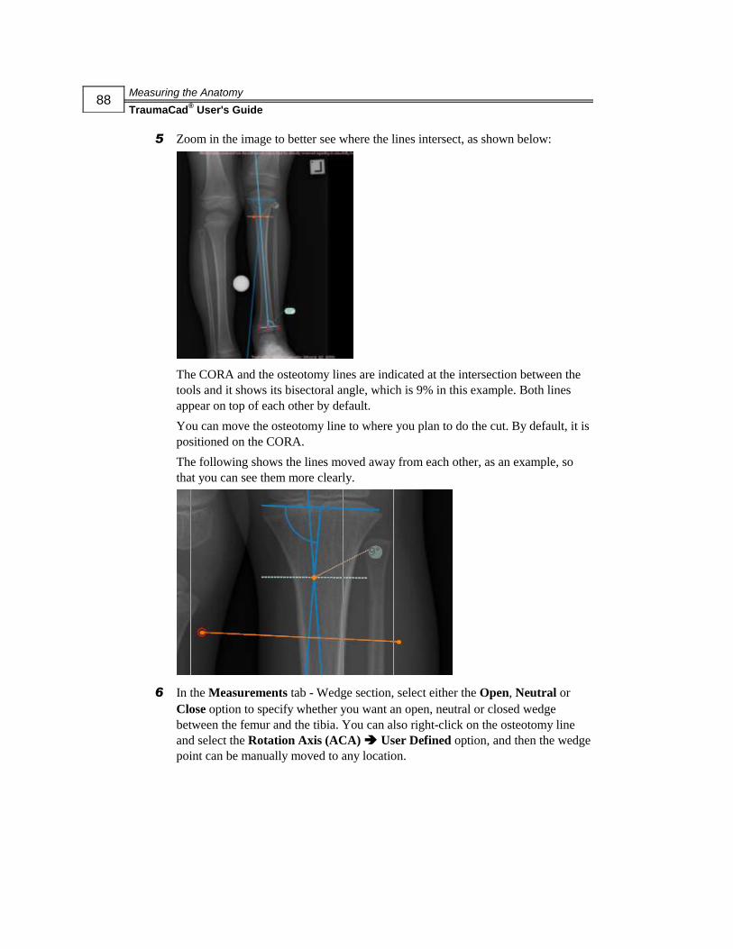
Measuring the Anatomy
TraumaCad® User's Guide
88
5 Zoom in the image to better see where the lines intersect, as shown below:
The CORA and the osteotomy lines are indicated at the intersection between the
tools and it shows its bisectoral angle, which is 9% in this example. Both lines
appear on top of each other by default.
You can move the osteotomy line to where you plan to do the cut. By default, it is
positioned on the CORA.
The following shows the lines moved away from each other, as an example, so
that you can see them more clearly.
6 In the Measurements tab - Wedge section, select either the Open, Neutral or
Close option to specify whether you want an open, neutral or closed wedge
between the femur and the tibia. You can also right-click on the osteotomy line
and select the Rotation Axis (ACA) User Defined option, and then the wedge
point can be manually moved to any location.
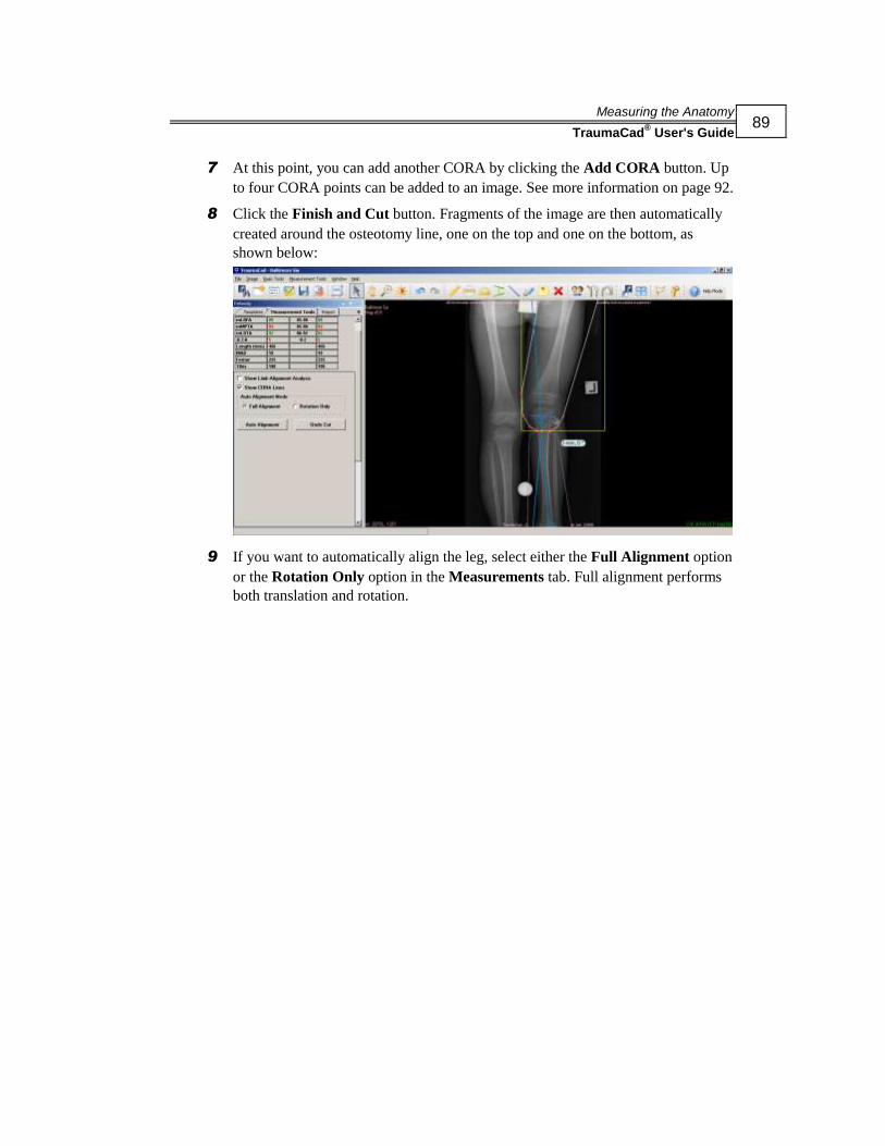
Measuring the Anatomy
TraumaCad® User's Guide
89
7 At this point, you can add another CORA by clicking the Add CORA button. Up
to four CORA points can be added to an image. See more information on page 92.
8 Click the Finish and Cut button. Fragments of the image are then automatically
created around the osteotomy line, one on the top and one on the bottom, as
shown below:
9 If you want to automatically align the leg, select either the Full Alignment option
or the Rotation Only option in the Measurements tab. Full alignment performs
both translation and rotation.

Measuring the Anatomy
TraumaCad® User's Guide
90
To automatically align the leg, click the Auto Alignment button in the
Measurements tab. The image fragments of the leg are then automatically
aligned, as shown below:
The new mechanical angles of the axes are shown in the Post column of the
Measurements tab, as shown below:
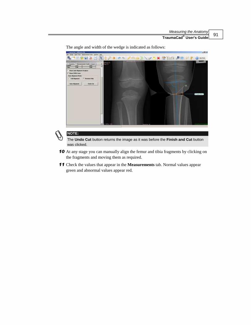
Measuring the Anatomy
TraumaCad® User's Guide
91
The angle and width of the wedge is indicated as follows:
NOTE:
The Undo Cut button returns the image as it was before the Finish and Cut button
was clicked.
10 At any stage you can manually align the femur and tibia fragments by clicking on
the fragments and moving them as required.
11 Check the values that appear in the Measurements tab. Normal values appear
green and abnormal values appear red.
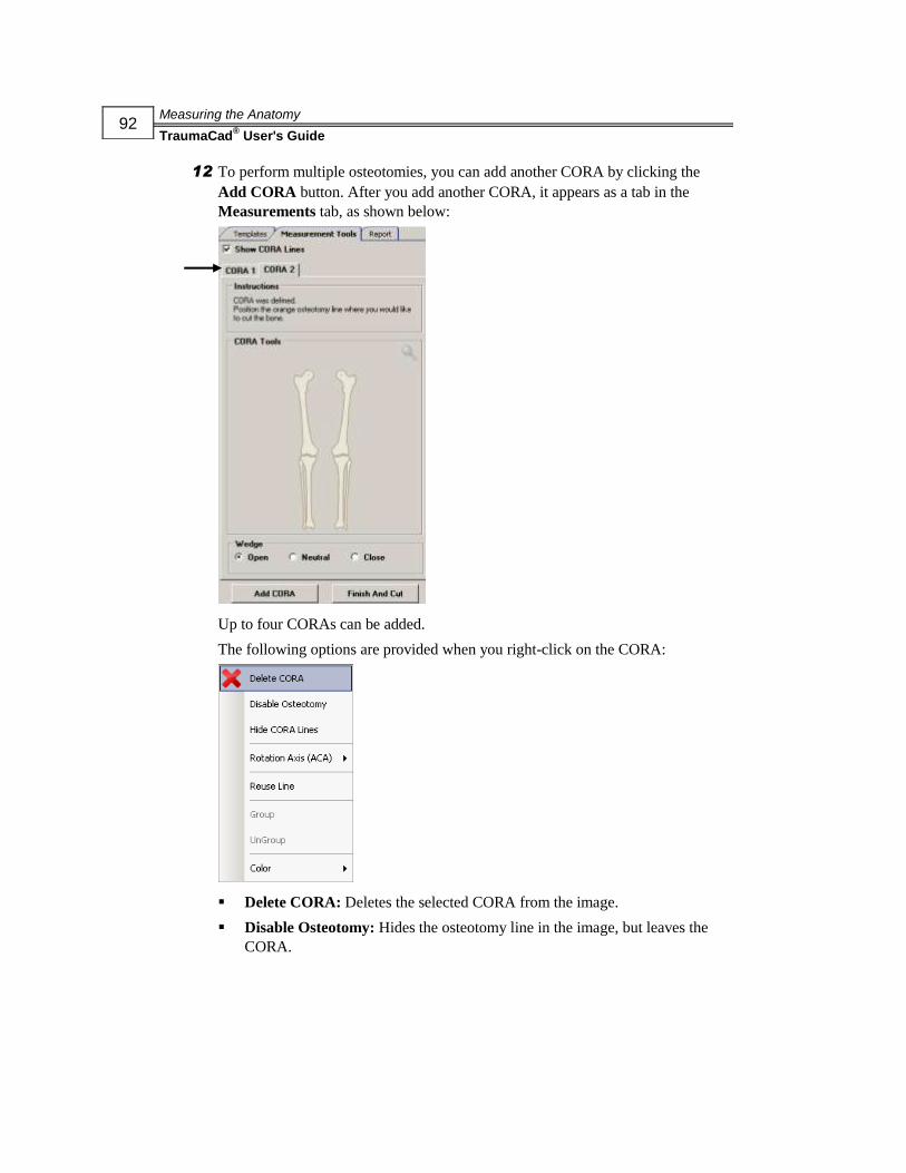
Measuring the Anatomy
TraumaCad® User's Guide
92
12 To perform multiple osteotomies, you can add another CORA by clicking the
Add CORA button. After you add another CORA, it appears as a tab in the
Measurements tab, as shown below:
Up to four CORAs can be added.
The following options are provided when you right-click on the CORA:
Delete CORA: Deletes the selected CORA from the image.
Disable Osteotomy: Hides the osteotomy line in the image, but leaves the
CORA.

Measuring the Anatomy
TraumaCad® User's Guide
93
Hide/Show CORA Lines: Hides/shows the CORA lines in the image.
Rotation Axis (ACA): After the level of osteotomy is defined, the type of
wedge can be selected. An open vs. closed wedge, neutral (through the
CORA) or manually positioned pivot can be selected for the moving
fragment.
Reuse Line: Automatically creates another CORA line (for example CORA
2) with the same definitions, which you can then modify.
Group: Groups multiple objects so they can be moved together as a single
object.
UnGroup: Removes objects from a group.
Color: Enables you to specify the color of the tools in the image.
13 Select the Reports tab to generate a report, as described on page 169.
The report shows all relevant information, such as the pre- and post-
measurements results, original image and the image after preparation.

Measuring the Anatomy
TraumaCad® User's Guide
94
Hip Measurements
The following hip measurements can be made using TraumaCad measurements tools:
Hip Deformity Analysis, page 95
Leg Length Discrepancy Tool, page 100
Acetabular Index, page 101
VCA Angle of Lequesne, page 102
Cup Version, page 103
Center of Rotation, page 104
Stem Version, page 105
NOTE:
After you have added a stem and a cup, you can right-click on the stem and select the
Attach To Cup option to automatically attach them together so that their attachment points
are positioned on top of each other. A default attachment point is automatically selected,
but you can modify it as required.

Measuring the Anatomy
TraumaCad® User's Guide
95
Hip Deformity Analysis
Follow the step-by-step instructions of the wizard. In the wizard, you mark the
specified anatomical locations in order to measure the important angles of hip
deformity.
► To use the Hip Deformity Analysis tool:
1 Select the Hip Deformity Analysis option in the Measurement Tools tab:

Measuring the Anatomy
TraumaCad® User's Guide
96
A window such as the following appears:
The Magnifying Glass tool is opened to help fine tune and to ensure that your
markers are located in the correct, exact position.
The Hip Deformity Analysis measurement tool is a wizard consisting of 10 steps.
NOTE:
Click the Back To Measurements List button to exit the wizard and
return to the list of measurement tools. This button is available in all measurement
tool wizards.

Measuring the Anatomy
TraumaCad® User's Guide
97
2 Follow the steps in the wizard and mark the relevant points on the image
corresponding to each step.
After completing step 9, the window appears, as shown below:
3 Enter the last (tenth) measurement.
4 Click OK to close the message box. The window now appears as shown below:
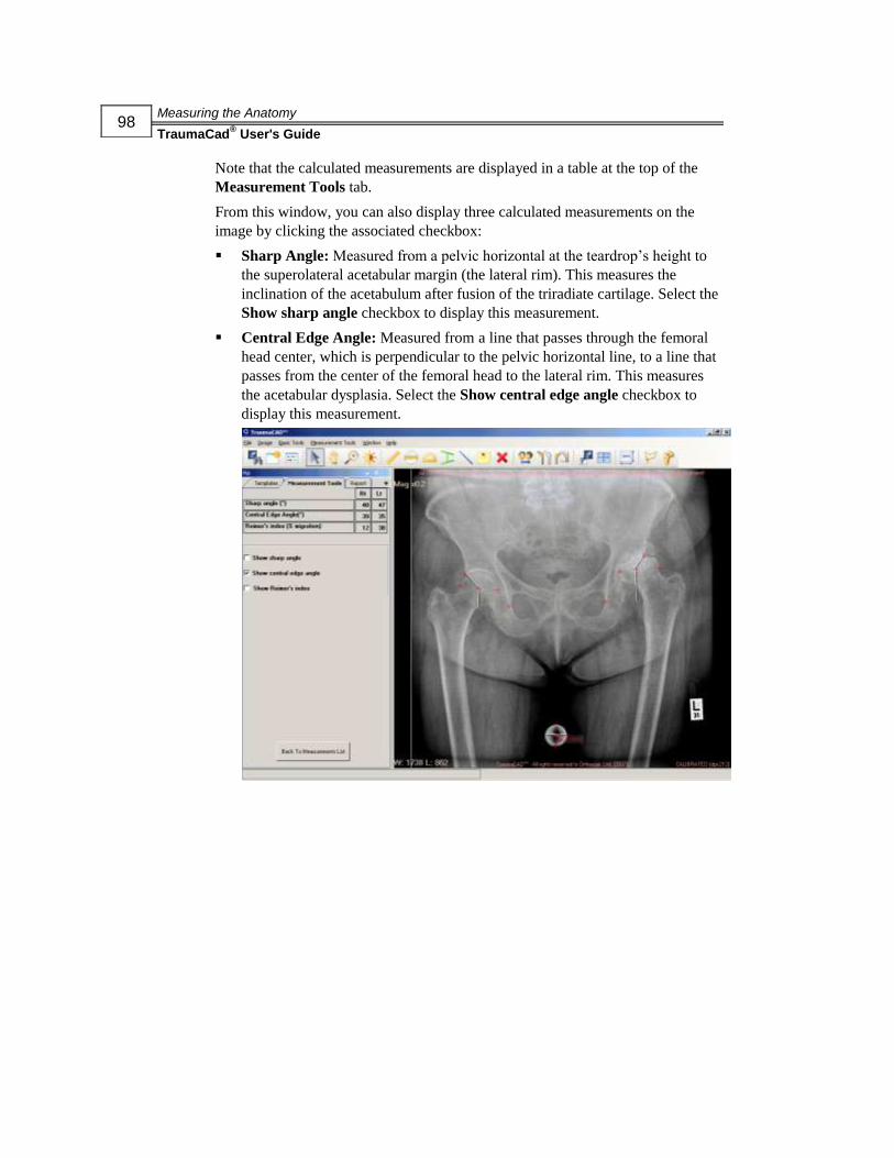
Measuring the Anatomy
TraumaCad® User's Guide
98
Note that the calculated measurements are displayed in a table at the top of the
Measurement Tools tab.
From this window, you can also display three calculated measurements on the
image by clicking the associated checkbox:
Sharp Angle: Measured from a pelvic horizontal at the teardrop’s height to
the superolateral acetabular margin (the lateral rim). This measures the
inclination of the acetabulum after fusion of the triradiate cartilage. Select the
Show sharp angle checkbox to display this measurement.
Central Edge Angle: Measured from a line that passes through the femoral
head center, which is perpendicular to the pelvic horizontal line, to a line that
passes from the center of the femoral head to the lateral rim. This measures
the acetabular dysplasia. Select the Show central edge angle checkbox to
display this measurement.
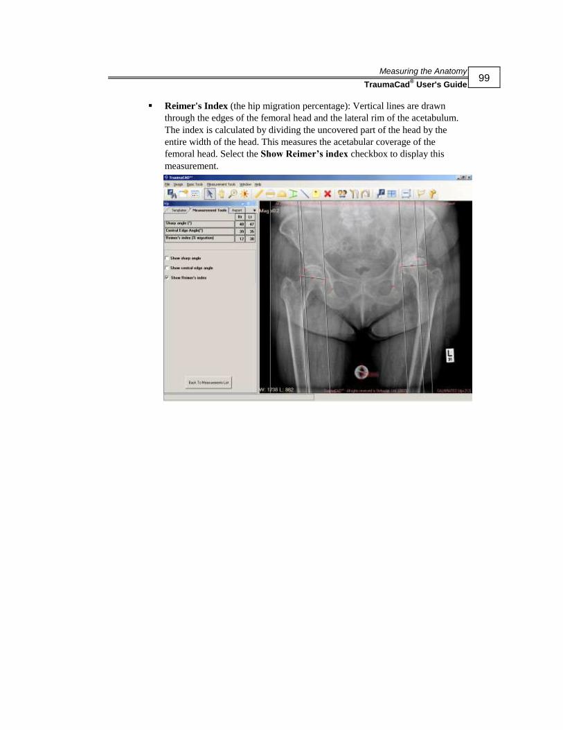
Measuring the Anatomy
TraumaCad® User's Guide
99
Reimer's Index (the hip migration percentage): Vertical lines are drawn
through the edges of the femoral head and the lateral rim of the acetabulum.
The index is calculated by dividing the uncovered part of the head by the
entire width of the head. This measures the acetabular coverage of the
femoral head. Select the Show Reimer’s index checkbox to display this
measurement.

Measuring the Anatomy
TraumaCad® User's Guide
100
Leg Length Discrepancy Tool
The Leg Length Discrepancy measurement tool enables you to measure leg length
discrepancy.
A tangent line is drawn by choosing two points at the most inferior points on the
ischial tuberosities. From this reference line, two vertical lines should be drawn as
identical anatomical landmarks on each proximal femur (the center of the lesser
trochanter, top of the greater trochanter and so on).
► To use the Leg Length Discrepancy tool:
1 Select the Leg Length Discrepancy option in the Measurement Tools tab or
select Measurement Tools Hip Leg Length Discrepancy. The tool
appears on the image:
2 Using the red markers, adjust the tool to the reference points in order to measure
the leg length discrepancy, meaning the ischial tuberosity and the center of the
lesser trochanter.
The text below the horizontal line indicates the discrepancy between the right and
left side and the distance between the two points. If there is no discrepancy, the
number 0 is shown.
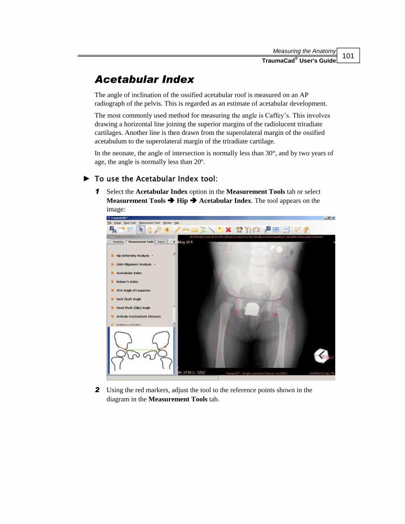
Measuring the Anatomy
TraumaCad® User's Guide
101
Acetabular Index
The angle of inclination of the ossified acetabular roof is measured on an AP
radiograph of the pelvis. This is regarded as an estimate of acetabular development.
The most commonly used method for measuring the angle is Caffey’s. This involves
drawing a horizontal line joining the superior margins of the radiolucent triradiate
cartilages. Another line is then drawn from the superolateral margin of the ossified
acetabulum to the superolateral margin of the triradiate cartilage.
In the neonate, the angle of intersection is normally less than 30°, and by two years of
age, the angle is normally less than 20º.
► To use the Acetabular Index tool:
1 Select the Acetabular Index option in the Measurement Tools tab or select
Measurement Tools Hip Acetabular Index. The tool appears on the
image:
2 Using the red markers, adjust the tool to the reference points shown in the
diagram in the Measurement Tools tab.

Measuring the Anatomy
TraumaCad® User's Guide
102
VCA Angle of Lequesne
The anterior center-edge (VCA) angle quantifies the anterior coverage of the femoral
head. Angles less than 20° are considered abnormal.
The VCA angle is calculated from a false-profile radiological view of the pelvis. The
patient stands at an angle of 65° oblique to the X-ray beam, with the foot on the
affected side parallel to the X-ray cassette. A vertical line through the center of the
femoral head subtends the VCA angle by connecting with a second line through the
center of the hip and the foremost aspect of the acetabulum.
► To access the VCA Angle of Lequesne tool:
Select the VCA Angle of Lequesne option in the Measurement Tools tab or
select Measurement Tools Hip VCA Angle of Lequesne. The tool
appears on the image, as shown below:

Measuring the Anatomy
TraumaCad® User's Guide
103
Cup Version
When the acetabular component of a total hip replacement is viewed at an angle, it
projects as an ellipse. This projection can be mathematically proven to follow the
general formula of an ellipse, and translated to ante/retroversion.
A horizontal reference line is drawn on the pelvis (between the ischial tuberosities,
teardrops and so on) and three red markers are placed on the edge of the cup. The
projection of the ellipse is then translated into ante/retroversion of the cup.
The image has to be a true AP pelvic image. Otherwise, the measured
ante/retroversion will be miscalculated.
► To access the Cup Version tool:
Select the Cup Version option in the Measurement Tools tab or select
Measurement Tools Hip Cup Version. The tool appears on the image, as
shown below:
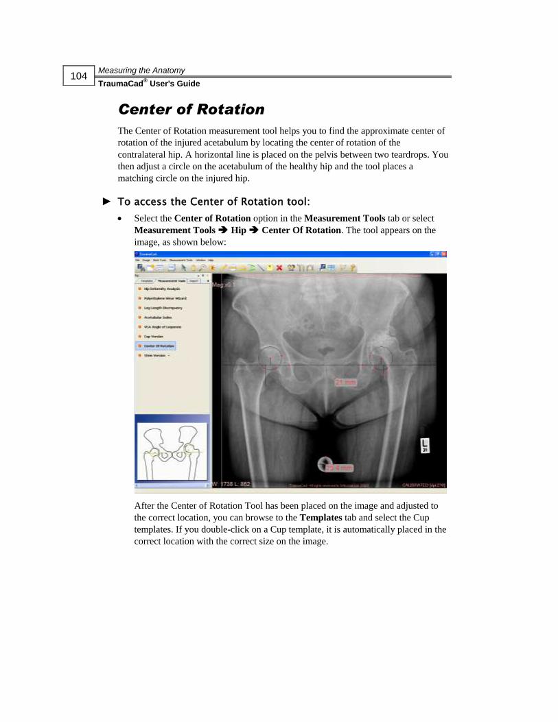
Measuring the Anatomy
TraumaCad® User's Guide
104
Center of Rotation
The Center of Rotation measurement tool helps you to find the approximate center of
rotation of the injured acetabulum by locating the center of rotation of the
contralateral hip. A horizontal line is placed on the pelvis between two teardrops. You
then adjust a circle on the acetabulum of the healthy hip and the tool places a
matching circle on the injured hip.
► To access the Center of Rotation tool:
Select the Center of Rotation option in the Measurement Tools tab or select
Measurement Tools Hip Center Of Rotation. The tool appears on the
image, as shown below:
After the Center of Rotation Tool has been placed on the image and adjusted to
the correct location, you can browse to the Templates tab and select the Cup
templates. If you double-click on a Cup template, it is automatically placed in the
correct location with the correct size on the image.

Measuring the Anatomy
TraumaCad® User's Guide
105
Stem Version
When the femoral component of a total hip replacement is ante/retroverted, the
projected neck-shaft angle changes accordingly. The new projected neck-shaft angle
can be mathematically translated to ante/retroversion of the stem.
First define the neck shaft angle of the selected stem from the dropdown list then, a
center-line finder is placed on the femoral stem, two red markers are placed on the
femoral neck and three red markers are placed on the edges of the implanted head.
The projection of the neck-shaft angle is then translated into the ante/retroversion of
the stem.
The image must be a true AP pelvic one with neutral rotation of the hip joint.
Otherwise, the measured ante/retroversion will be miscalculated.
► To access the Stem Version tool:
Select the Stem Version option in the Measurement Tools tab or select
Measurement Tools Hip Stem Version. The tool appears on the image, as
shown below:
Measuring the Anatomy
TraumaCad® User's Guide
106
Knee Measurements
The following knee measurements can be made using TraumaCad measurements
tools:
Limb Alignment Analysis, below
Center Line Finder, page 107
Simple Line, page 108
High Tibial Osteotomy, page 109
Tibial Cutting, page 110
Joint Line, page 111
Limb Alignment Analysis
Knee limb alignment analysis enables orthopedic surgeons to take unilateral or
bilateral anatomical measurements, compare them to normative standards and to
simulate corrective procedures. Easy-to-use wizards help surgeons produce a wide
range of anatomical measurements.
The steps for using this tool are the same as those described in the Limb Alignment
Analysis section on page 80. Consult this section and its subsections for more details.
► To access the Knee Limb Alignment Analysis tool:
Select the Limb Alignment Analysis option in the Measurement Tools tab. The
tool appears on the image.

Measuring the Anatomy
TraumaCad® User's Guide
107
Center Line Finder
The Center Line Finder measurement tool is used to locate the center line of long
bones. After adjusting the four points to the edges of the bone, the center line is
displayed.
► To access the Center Line Finder tool:
Select the Center Line Finder option in the Measurement Tools tab or select
Measurement Tools Knee Center Line Finder. The tool appears on the
image, as shown below:

Measuring the Anatomy
TraumaCad® User's Guide
108
Simple Line
Using this tool, a line is displayed on the image that can be manipulated. If the line
crosses a second line, such as a Center line or Joint line, the angle between the lines is
calculated.
► To access the Simple Line tool:
Select the Simple Line option in the Measurement Tools tab or select
Measurement Tools Knee Simple Line. The tool appears on the image, as
shown below:

Measuring the Anatomy
TraumaCad® User's Guide
109
High Tibial Osteotomy
This measurement tool is used to measure the correction angle of a High Tibial
Osteotomy (HTO), which is the angle between a line that is drawn from the center of
the femur to the 62% coordinate of the knee, and a line from the 62% coordinate to
the center of the tibiotalar joint.
► To access the High Tibial Osteotomy tool:
Select the High Tibial Osteotomy option in the Measurement Tools tab or
select Measurement Tools Knee High Tibial Osteotomy. The tool
appears on the image, as shown below. Place the circle around the femoral head,
the middle line on the tibial plateau and the distal line on the tibial plafond.

Measuring the Anatomy
TraumaCad® User's Guide
110
Tibial Cutting
The Tibial Cutting measurement tool measures the amount of bone to be cut at the
medial and lateral compartments of the knee in a total knee replacement.
A center line finder is placed on the tibia. A line perpendicular to the center line is
drawn proximally and should be placed at the location of the tibial cutting. Two rulers
are located at the edges of the tibial cutting line and should be adjusted to the tibial
articular surfaces.
► To access the Tibial Cutting tool:
Select the Tibial Cutting option in the Measurement Tools tab or select
Measurement Tools Knee Tibial Cutting. The tool appears on the image,
as shown below:
After the Tibial Cutting Tool has been placed on the image and adjusted to the
correct location, you can browse to the Templates tab and select a Tibial
template. If you double-click on a Tibial template, it is automatically placed in the
correct location with the correct size on the image. If you then double-click on a
Femoral template, it is automatically placed in the correct location with the
correct size on the image.
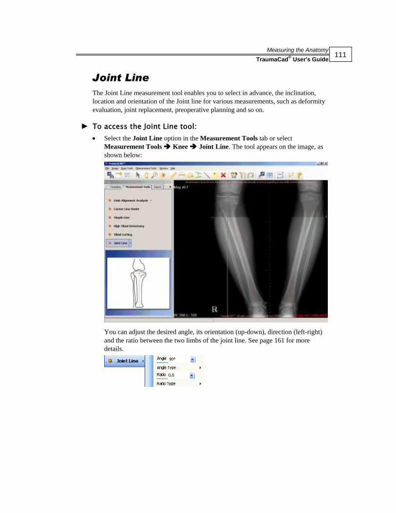
Measuring the Anatomy
TraumaCad® User's Guide
111
Joint Line
The Joint Line measurement tool enables you to select in advance, the inclination,
location and orientation of the Joint line for various measurements, such as deformity
evaluation, joint replacement, preoperative planning and so on.
► To access the Joint Line tool:
Select the Joint Line option in the Measurement Tools tab or select
Measurement Tools Knee Joint Line. The tool appears on the image, as
shown below:
You can adjust the desired angle, its orientation (up-down), direction (left-right)
and the ratio between the two limbs of the joint line. See page 161 for more
details.

Measuring the Anatomy
TraumaCad® User's Guide
112
Pediatric Measurements
The following pediatric measurements can be made using TraumaCad measurements
tools:
Hip Deformity Analysis, below
Limb Alignment Analysis, page 117
Acetabular Index, page 118
Reimer’s Index, page 119
VCA Angle of Lequesne, page 120
Neck Shaft Angle, page 121
Head Shaft (Slip) Angle, page 122
Articulo-trochanteric Distance, page 123
Epiphyseal Index, page 124
Tibiofemoral Angle, page 125
Metaphyseal-Diaphyseal Angle, page 126
Hip Deformity Analysis
When using this measurement tool, first select the module that fits the patient’s bone
age by the ossification stage of the femoral head. The options are:
Fused Triradiate Cartilage
Full/Partly Ossified Femoral Head
Non-Ossified Femoral Head

Measuring the Anatomy
TraumaCad® User's Guide
113
► To use the Hip Deformity Analysis tool for pediatric
measurements:
1 Select the Hip Deformity Analysis option in the Measurement Tools tab, as
shown below:

Measuring the Anatomy
TraumaCad® User's Guide
114
2 Select the appropriate module in the dropdown list. A window such as the
following appears:
The Hip Deformity Analysis measurement tool is a wizard consisting of 10 steps.
NOTE:
Click the Back To Measurements List button to exit the wizard and
return to the list of measurement tools. This button is available in all measurement
tool wizards.

Measuring the Anatomy
TraumaCad® User's Guide
115
3 Follow the steps in the wizard and mark the relevant points on the image
corresponding to each step.
A magnifying glass opens automatically that enlarges the relevant area to help
you position the points.
After completing step 9, a window appears as shown below:
4 Enter the last (tenth) measurement.

Measuring the Anatomy
TraumaCad® User's Guide
116
5 Click OK to close the message box. The window now appears as shown below:
Note that the calculated measurements are displayed in the table at the top of the
Measurement Tools tab.
From this window, you can also display three calculated measurements on the
image, as follows:
Hilgenreiner Angle: The angle of inclination of the ossified acetabular roof
is measured on an AP radiograph of the pelvis. This is regarded as an
estimate of acetabular development. The most commonly used method for
measuring the angle is Caffey’s. This involves drawing a horizontal line
joining the superior margins of the radiolucent triradiate cartilages. Another
line is then drawn from the superolateral margin of the ossified acetabulum to
the superolateral margin of the triradiate cartilage. In the neonate, the angle of
intersection is normally less than 30°, and by two years of age, the angle is
normally less than 20º. Select the Show Hilgenreiner Angle checkbox to
display this measurement.
Central Edge Angle: This angle is measured from a line that passes through
the femoral head center and is perpendicular to the pelvic horizontal line, to a
line that passes from the center of the femoral head to the lateral rim. It
measures the acetabular dysplasia. Select the Show Central Edge Angle
checkbox to display this measurement.
Reimer's Index (the hip migration percentage): Vertical lines are drawn
through the edges of the femoral head and the lateral rim of the acetabulum.
The index is calculated by dividing the uncovered part of the head by the
entire width of the head, which measures the acetabular coverage of the
femoral head. Select the Show Reimer’s Index checkbox to display this
measurement.

Measuring the Anatomy
TraumaCad® User's Guide
117
Limb Alignment Analysis
Pediatric limb alignment analysis enables orthopedic surgeons to take unilateral or
bilateral anatomical measurements, compare them to normative standards and to
simulate corrective procedures. Easy-to-use wizards help surgeons produce a wide
range of anatomical measurements. Each measurement is automatically compared to
the normal parameters published in the literature and to the contralateral limb in the
bilateral module, providing instant evaluations of patient anatomy. Measurements and
evaluations integrate into patient files for an easy transition to digital radiology.
The steps for using this tool are the same as those described in the Limb Alignment
Analysis section on page 80. Consult this section and its subsections for more details.
► To access the pediatric Limb Alignment Analysis tool:
Select the Limb Alignment Analysis option in the Measurement Tools tab. The
tool appears on the image.

Measuring the Anatomy
TraumaCad® User's Guide
118
Acetabular Index
The angle of inclination of the ossified acetabular roof is measured on an AP
radiograph of the pelvis. This is regarded as an estimate of acetabular development.
The most commonly used method for measuring the angle is Caffey’s. This involves
drawing a horizontal line joining the superior margins of the radiolucent triradiate
cartilages. Another line is then drawn from the superolateral margin of the ossified
acetabulum to the superolateral margin of the triradiate cartilage.
In the neonate, the angle of intersection is normally less than 30°, and by two years of
age the angle is normally less than 20º.
► To access the pediatric Acetabular Index tool:
Select the Acetabular Index option in the Measurement Tools tab or select
Measurement Tools Pediatric Acetabular Index. The tool appears on the
image, as shown below:

Measuring the Anatomy
TraumaCad® User's Guide
119
Reimer’s Index
The Reimer’s Index measures the hip migration percentage. A circle is adjusted to the
ossified femoral head. The vertical line is then placed continuous with the lateral rim
of the acetabulum. The index is calculated by dividing the lateral part of the circle by
the diameter of the circle. This measures the acetabular coverage of the femoral head.
► To access the Reimer’s Index tool:
Select the Reimer’s Index option in the Measurement Tools tab or select
Measurement Tools Pediatric Reimer’s Index. The tool appears on the
image, as shown below:

Measuring the Anatomy
TraumaCad® User's Guide
120
VCA Angle of Lequesne
The anterior center-edge (VCA) angle quantifies the anterior coverage of the femoral
head. Angles of less than 20° are considered abnormal.
The VCA angle is calculated from a false-profile radiological view of the pelvis. The
patient stands at an angle of 65° oblique to the X-ray beam, with the foot on the
affected side parallel to the X-ray cassette. A vertical line through the center of the
femoral head subtends the VCA angle by connecting with a second line through the
center of the hip and the foremost aspect of the acetabulum.
► To access the pediatric VCA Angle of Lequesne tool:
Select the VCA Angle of Lequesne option in the Measurement Tools tab or
select Measurement Tools Pediatric VCA Angle of Lequesne. The tool
appears on the image, as shown below:

Measuring the Anatomy
TraumaCad® User's Guide
121
Neck Shaft Angle
Hip deformity can be evaluated by measuring the angle between the center of the shaft
and the center of the neck of the femur.
The normal femoral neck-shaft angle in children changes with age, being
approximately 150 at birth and gradually reducing to approach the adult value of 130.
It is important that the radiograph is taken with the patient correctly positioned with
the leg held in a neutral position and the patellae facing forward, as external rotation
of the leg increases and internal rotation decreases the projected neck-shaft angle.
► To access the Neck Shaft Angle tool:
Select the Neck Shaft Angle option in the Measurement Tools tab or select
Measurement Tools Pediatric Neck Shaft Angle. The tool appears on the
image, as shown below:
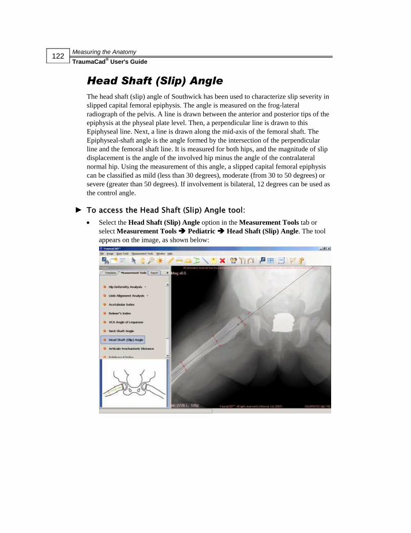
Measuring the Anatomy
TraumaCad® User's Guide
122
Head Shaft (Slip) Angle
The head shaft (slip) angle of Southwick has been used to characterize slip severity in
slipped capital femoral epiphysis. The angle is measured on the frog-lateral
radiograph of the pelvis. A line is drawn between the anterior and posterior tips of the
epiphysis at the physeal plate level. Then, a perpendicular line is drawn to this
Epiphyseal line. Next, a line is drawn along the mid-axis of the femoral shaft. The
Epiphyseal-shaft angle is the angle formed by the intersection of the perpendicular
line and the femoral shaft line. It is measured for both hips, and the magnitude of slip
displacement is the angle of the involved hip minus the angle of the contralateral
normal hip. Using the measurement of this angle, a slipped capital femoral epiphysis
can be classified as mild (less than 30 degrees), moderate (from 30 to 50 degrees) or
severe (greater than 50 degrees). If involvement is bilateral, 12 degrees can be used as
the control angle.
► To access the Head Shaft (Slip) Angle tool:
Select the Head Shaft (Slip) Angle option in the Measurement Tools tab or
select Measurement Tools Pediatric Head Shaft (Slip) Angle. The tool
appears on the image, as shown below:
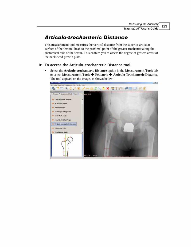
Measuring the Anatomy
TraumaCad® User's Guide
123
Articulo-trochanteric Distance
This measurement tool measures the vertical distance from the superior articular
surface of the femoral head to the proximal point of the greater trochanter along the
anatomical axis of the femur. This enables you to assess the degree of growth arrest of
the neck-head growth plate.
► To access the Articulo-trochanteric Distance tool:
Select the Articulo-trochanteric Distance option in the Measurement Tools tab
or select Measurement Tools Pediatric Articulo-Trochanteric Distance.
The tool appears on the image, as shown below:

Measuring the Anatomy
TraumaCad® User's Guide
124
Epiphyseal Index
The Epiphyseal Index is the quotient between the largest width and the largest height
of the epiphyseal nucleus, measured on the X-ray plate and shown in percentage of
sphericity. This provides an indication of the degree of flattening of the epiphyseal
nucleus induced by necrosis or mechanical deformity.
► To access the Epiphyseal Index tool:
Select the Epiphyseal Index option in the Measurement Tools tab or select
Measurement Tools Pediatric Epiphyseal Index. The tool appears on the
image, as shown below:
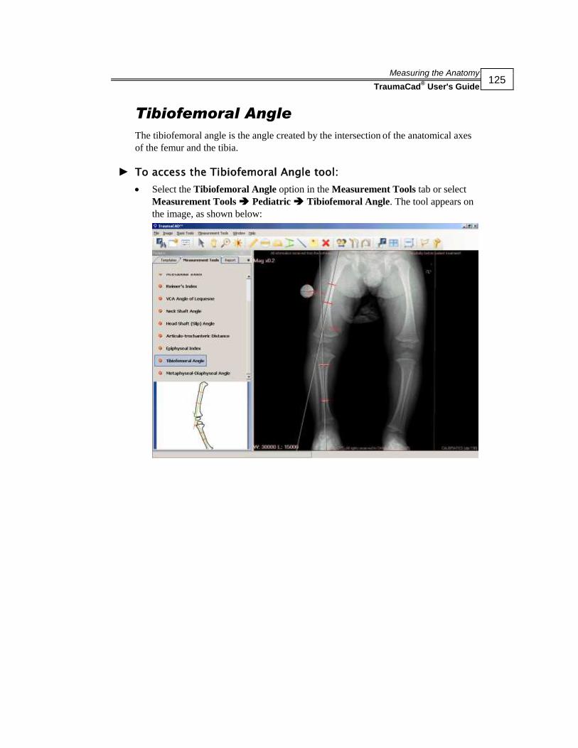
Measuring the Anatomy
TraumaCad® User's Guide
125
Tibiofemoral Angle
The tibiofemoral angle is the angle created by the intersection of the anatomical axes
of the femur and the tibia.
► To access the Tibiofemoral Angle tool:
Select the Tibiofemoral Angle option in the Measurement Tools tab or select
Measurement Tools Pediatric Tibiofemoral Angle. The tool appears on
the image, as shown below:

Measuring the Anatomy
TraumaCad® User's Guide
126
Metaphyseal-Diaphyseal Angle
The metaphyseal-diaphyseal angle is the angle created by the intersection of a line
through the transverse plane of the proximal tibial metaphysis, with a line
perpendicular to the long axis of the tibial diaphysis. This angle represents the degree
of deformity of the proximal end of the tibia in a patient with clinical bowleg
deformity, and permits early differentiation between infantile tibia vara and
physiological bowleg before the appearance of the radiographic changes of tibia vara.
► To access the Metaphyseal-Diaphyseal Angle tool:
Select the Metaphyseal-Diaphyseal Angle option in the Measurement Tools tab
or select Measurement Tools Pediatric Metaphyseal-Diaphyseal Angle.
The tool appears on the image, as shown below:

Measuring the Anatomy
TraumaCad® User's Guide
127
Trauma Measurements
The following trauma measurements can be made using TraumaCad measurements
tools:
Limb Alignment Analysis, below
Diaphyseal Fracture Angulation, page 128
Metaphyseal Fracture Angulation, page 129
Center Line Finder, page 129
Simple Line, page 130
Roof Arc, page 130
Joint Line, page 131
Limb Alignment Analysis
Trauma limb alignment analysis enables orthopedic surgeons to take unilateral or
bilateral anatomical measurements, compare them to normative standards and to
simulate corrective procedures. Easy-to-use wizards help surgeons produce a wide
range of anatomical measurements. Each measurement is automatically compared to
the normal parameters published in the literature and to the contralateral limb in the
bilateral module, providing instant evaluations of patient anatomy. Measurements and
evaluations integrate into patient files for an easy transition to digital radiology.
The steps for using this tool are the same as those described in the Limb Alignment
Analysis section on page 80. Consult this section and its subsections for more details.
► To access the trauma Limb Alignment Analysis tool:
Select the Limb Alignment Analysis option in the Measurement Tools tab. The
tool appears on the image.

Measuring the Anatomy
TraumaCad® User's Guide
128
Diaphyseal Fracture Angulation
This measurement tool measures the angle between the long axes of two long bones.
The points are adjusted to the edges of the bones and the angle between their center
lines is measured and displayed.
► To access the Diaphyseal Fracture Angulation tool:
Select the Diaphyseal Fracture Angulation option in the Measurement Tools
tab or select Measurement Tools Trauma Diaphyseal Fracture
Angulation. The tool appears on the image, as shown below:

Measuring the Anatomy
TraumaCad® User's Guide
129
Metaphyseal Fracture Angulation
This tool measures the angle between the long axis of a long bone and the joint line of
the bone. The points are adjusted to the edges of the bone and its articular surface and
the angle between them is measured and displayed.
► To access the Metaphyseal Fracture Angulation tool:
Select the Metaphyseal Fracture Angulation option in the Measurement Tools
tab or select Measurement Tools Trauma Metaphyseal Fracture
Angulation. The tool appears on the image, as shown below:
Center Line Finder
The Center Line Finder measurement tool is used for locating the center line of long
bones. Adjust the four points to the edges of the bone to display the center line. This
tool works as described on page 107. Consult this section for more details.
► To access the trauma Center Line Finder tool:
Select the Center Line Finder option in the Measurement Tools tab. The tool
appears on the image.

Measuring the Anatomy
TraumaCad® User's Guide
130
Simple Line
The Simple Line tool displays a line on the image that can be manipulated. If the line
crosses a second line, such as a Center line or Joint line, the angle between them is
calculated. This tool works as described on page 108. Consult this section for more
details.
► To access the trauma Simple Line tool:
Select the Simple Line option in the Measurement Tools tab. The tool appears
on the image.
Roof Arc
The roof arc concept was originally described by Matta. It helps determine the amount
of intact acetabular dome and is a useful method for determining the need for surgery.
Measurements are made on AP, obturator and iliac oblique views, as follows:
A vertical line is drawn to the geometric center of the acetabulum.
Another line is drawn through a point where a fracture line intersects the
acetabulum and again to the geometric center of the acetabulum.
Angles drawn in this way represent medial, anterior or posterior roof arcs as seen
on AP, obturator oblique or iliac views, respectively.

Measuring the Anatomy
TraumaCad® User's Guide
131
► To access the Roof Arc tool:
Select the Roof Arc option in the Measurement Tools tab or select
Measurement Tools Trauma Roof Arc. The tool appears on the image,
as shown below:
Joint Line
The Joint Line measurement tool enables you to select, in advance, the inclination,
location and orientation of the Joint line for various measurements, such as deformity
evaluation, joint replacement, preoperative planning and so on. This tool works as
described on page 161. Consult this section for more details.
► To access the trauma Joint Line tool:
Select the Joint Line option in the Measurement Tools tab. The tool appears on
the image.

Measuring the Anatomy
TraumaCad® User's Guide
132
Spine Measurements
The following spine measurements can be made using TraumaCad measurements
tools:
Vertebrae Labeling, below
Cobb Angle, page 135
Double Cobb Angle, page 136
Triple Cobb Angle, page 137
Pelvic Radius Angle, page 137
Sacral Obliquity, page 139
Coronal Balance, page 140
Sagittal Balance, page 141
Spondylolysthesis, page 142
Thoracic Kyphosis Angle, page 143
Thoracic Trunk Shift, page 144
T1 Tilt Angle, page 144
Lumbar Lordosis Angle, page 146
Spine Slip Angle, page 147
Vertebrae Labeling
This tool enables you to label spine vertebrae. There are various kinds of vertebrae,
including:
Cervical, designated by C on the image
Thoracic, designated by T on the image
Lumbar, designated by L on the image

Measuring the Anatomy
TraumaCad® User's Guide
133
► To use the Vertebrae Labeling tool:
1 Select the Vertebrae Labeling option in the Measurement Tools tab.The
following window opens:
2 Click the Cranial button to label cranial (superior) vertebrae, or click the Caudal
button to label caudal (inferior) vertebrae.
3 Select the first vertebra to label in the First Vertebra dropdown list, as shown
below:

Measuring the Anatomy
TraumaCad® User's Guide
134
4 Click the Yes or No button, as appropriate, to indicate whether there are abnormal
vertebrae. If you select Yes, select the appropriate radio button(s) for the
abnormal vertebra(ae).
5 Click Accept to label the first vertebra.
6 Click on the first vertebra you want to label. The label is added to the image.
7 Repeat step 6 as many times as needed to label additional vertebrae. TraumaCad
automatically moves to the next vertebra to assign the next label. It also takes any
abnormal vertebrae into account for this purpose.
8 After you have labeled the vertebrae in the image, click Finish. You can move the
labels on the image using standard TraumaCad methods.

Measuring the Anatomy
TraumaCad® User's Guide
135
Cobb Angle
The Cobb Angle measurement is used for evaluation of curves in scoliosis on an AP
radiographic projection of the spine.
When assessing a curve the apical vertebra is first identified. This is the most likely
displaced and rotated vertebra with the least tilted endplate. The end/transitional
vertebra are then identified through the curve above and below. The end vertebras are
the most superior and inferior vertebras that are least displaced and rotated and have
the maximally tilted endplate.
A line is drawn along the superior endplate of the superior end vertebra and a second
line is drawn along the inferior endplate of the inferior end vertebra. The angle
between these two lines is measured as the Cobb angle.
In S-shaped scoliosis, where there are two contiguous curves, the lower-end vertebra
of the upper curve represents the upper-end vertebra of the lower curve. In some
cases, there may be a third contiguous curve.
As a general rule, a Cobb angle of 10 is regarded as a minimum angulation to define
scoliosis.

Measuring the Anatomy
TraumaCad® User's Guide
136
► To access the Cobb Angle tool:
Select the Cobb Angle option in the Measurement Tools tab or select
Measurement Tools Spine Cobb Angle. The tool appears on the image,
as shown below:
Double Cobb Angle
The Double Cobb Angle measurement tool works the same as the Cobb Angle tool.
See page 135 for more details.
► To access the Double Cobb Angle tool:
Select the Double Cobb Angle option in the Measurement Tools tab or select
Measurement Tools Spine Double Cobb Angle. The tool appears on the
image.

Measuring the Anatomy
TraumaCad® User's Guide
137
Triple Cobb Angle
The Triple Cobb Angle measurement tool works the same as the Cobb Angle tool. See
page 135 for more details.
► To access the Triple Cobb Angle tool:
Select the Triple Cobb Angle option in the Measurement Tools tab or select
Measurement Tools Spine Triple Cobb Angle. The tool appears on the
image.
Pelvic Radius Angle
There are three different measurements that are used to describe pelvic morphology,
based on standing lateral radiographs:
Pelvisacral angle (PSA), which represents the angle between a line tangent to the
sacral endplate and the line through the center of the hip joints and the middle of
the sacral endplate.
Pelvic incidence (PI) angle, which is the complement angle to the pelvisacral
angle.
Pelvic lordosis angle (PLA), which represents the angle between a line tangent to
the sacral endplate and the line through the center of the hip joints and the
posterior aspect of the sacral endplate.
The PLA, PSA and PI are very similar and are equally good methods to assess pelvic
morphology.
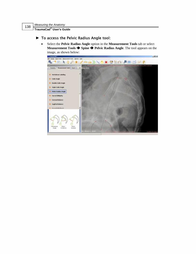
Measuring the Anatomy
TraumaCad® User's Guide
138
► To access the Pelvic Radius Angle tool:
Select the Pelvic Radius Angle option in the Measurement Tools tab or select
Measurement Tools Spine Pelvic Radius Angle. The tool appears on the
image, as shown below:

Measuring the Anatomy
TraumaCad® User's Guide
139
Sacral Obliquity
This tool measures the angular deviation of the sacrum from the line drawn parallel to
a line across the femoral heads on a supine AP view of the sacrum.
► To access the Sacral Obliquity tool:
Select the Sacral Obliquity option in the Measurement Tools tab or select
Measurement Tools Spine Sacral Obliquity. The tool appears on the
image, as shown below:

Measuring the Anatomy
TraumaCad® User's Guide
140
Coronal Balance
This tool measures the alignment of the spine on the coronal plane. The horizontal
distance between the midpoints of the C7 body to the center of the sacrum on an
upright long cassette PA radiograph of the spine is measured and displayed.
► To access the Coronal Balance tool:
Select the Coronal Balance option in the Measurement Tools tab or select
Measurement Tools Spine Coronal Balance. The tool appears on the
image, as shown below:
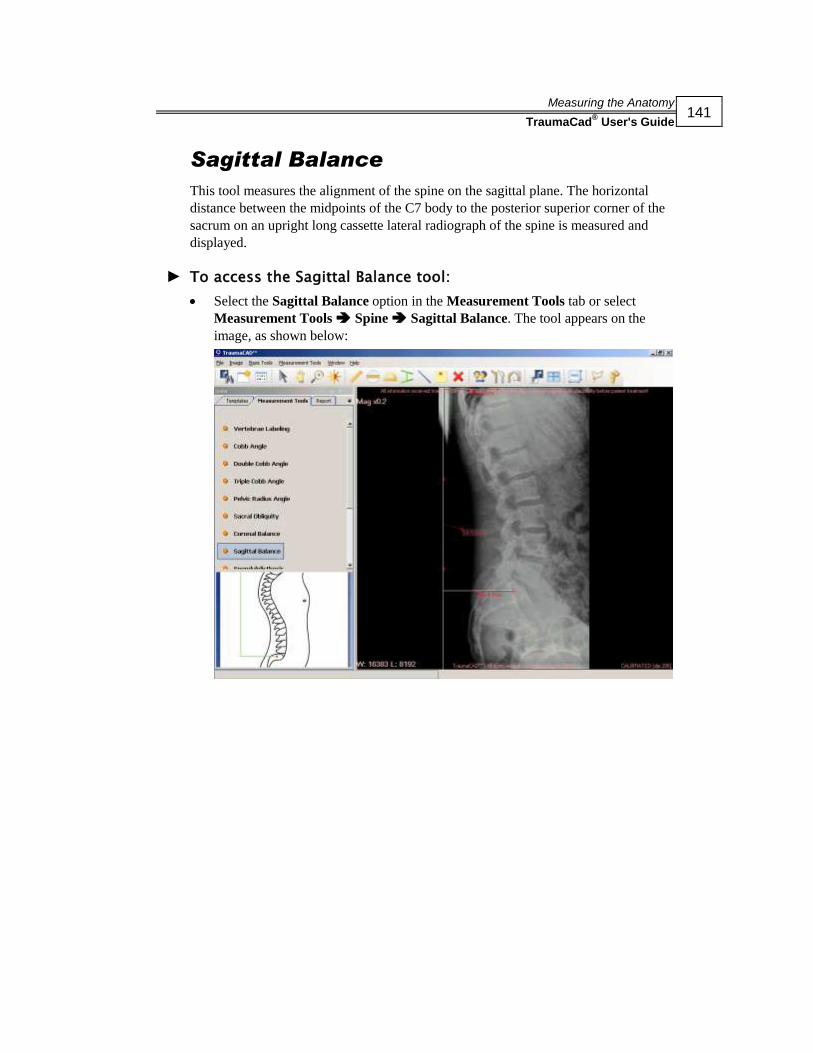
Measuring the Anatomy
TraumaCad® User's Guide
141
Sagittal Balance
This tool measures the alignment of the spine on the sagittal plane. The horizontal
distance between the midpoints of the C7 body to the posterior superior corner of the
sacrum on an upright long cassette lateral radiograph of the spine is measured and
displayed.
► To access the Sagittal Balance tool:
Select the Sagittal Balance option in the Measurement Tools tab or select
Measurement Tools Spine Sagittal Balance. The tool appears on the
image, as shown below:

Measuring the Anatomy
TraumaCad® User's Guide
142
Spondylolysthesis
Spondylolysthesis is forward slippage of a vertebra onto the next vertebra below it.
The most commonly used grading system for Spondylolysthesis is the one proposed
by Meyerding in 1947.
The degree of slippage is measured as the percentage of distance the anteriorly
translated vertebral body has moved forward relative to the superior endplate of the
vertebra below. Classifications use the following grading system:
Grade 0: No slippage
Grade 1: 1-25% slippage
Grade 2: 26-50% slippage
Grade 3: 51-75% slippage
Grade 4: 76-100% slippage
Grade 5: Greater than 100% slippage (spondyloptosis)
► To access the Spondylolysthesis tool:
Select the Spondylolysthesis option in the Measurement Tools tab or select
Measurement Tools Spine Spondylolysthesis. The tool appears on the
image, as shown below:
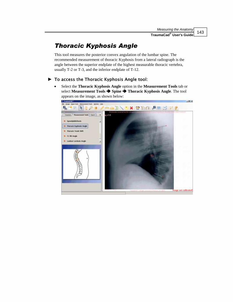
Measuring the Anatomy
TraumaCad® User's Guide
143
Thoracic Kyphosis Angle
This tool measures the posterior convex angulation of the lumbar spine. The
recommended measurement of thoracic Kyphosis from a lateral radiograph is the
angle between the superior endplate of the highest measurable thoracic vertebra,
usually T-2 or T-3, and the inferior endplate of T-12.
► To access the Thoracic Kyphosis Angle tool:
Select the Thoracic Kyphosis Angle option in the Measurement Tools tab or
select Measurement Tools Spine Thoracic Kyphosis Angle. The tool
appears on the image, as shown below:

Measuring the Anatomy
TraumaCad® User's Guide
144
Thoracic Trunk Shift
This tool measures the trunk shift from the center of a line at the height of the apical
thoracic vertebra to the central sacral vertebral line.
► To access the Thoracic Trunk Shift tool:
Select the Thoracic Trunk Shift option in the Measurement Tools tab or select
Measurement Tools Spine Thoracic Trunk Shift. The tool appears on
the image, as shown below:

Measuring the Anatomy
TraumaCad® User's Guide
145
T1 Tilt Angle
The angle between a line along the cephaled endplate of T1 to a line perpendicular to
the vertical edge of the radiograph.
► To access the T1 Tilt Angle tool:
Select the T1 Tilt Angle option in the Measurement Tools tab or select
Measurement Tools Spine T1 Tilt Angle. The tool appears on the image,
as shown below:
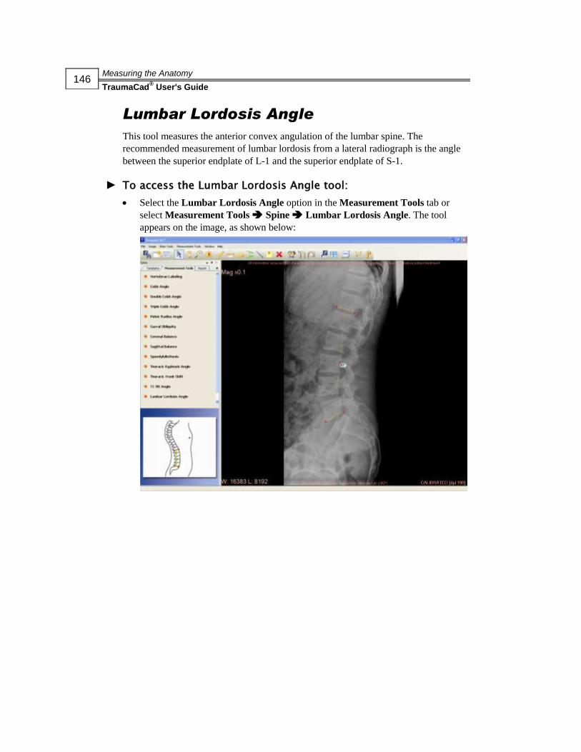
Measuring the Anatomy
TraumaCad® User's Guide
146
Lumbar Lordosis Angle
This tool measures the anterior convex angulation of the lumbar spine. The
recommended measurement of lumbar lordosis from a lateral radiograph is the angle
between the superior endplate of L-1 and the superior endplate of S-1.
► To access the Lumbar Lordosis Angle tool:
Select the Lumbar Lordosis Angle option in the Measurement Tools tab or
select Measurement Tools Spine Lumbar Lordosis Angle. The tool
appears on the image, as shown below:
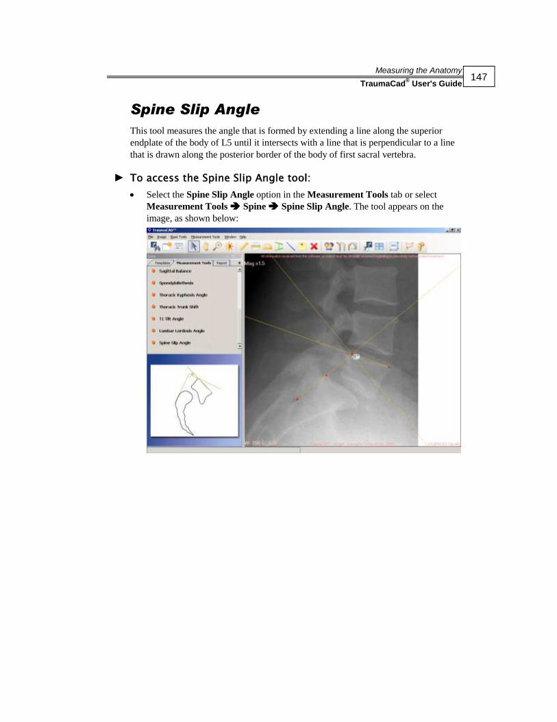
Measuring the Anatomy
TraumaCad® User's Guide
147
Spine Slip Angle
This tool measures the angle that is formed by extending a line along the superior
endplate of the body of L5 until it intersects with a line that is perpendicular to a line
that is drawn along the posterior border of the body of first sacral vertebra.
► To access the Spine Slip Angle tool:
Select the Spine Slip Angle option in the Measurement Tools tab or select
Measurement Tools Spine Spine Slip Angle. The tool appears on the
image, as shown below:
Measuring the Anatomy
TraumaCad® User's Guide
148
Foot and Ankle Tools
The following foot and ankle measurements can be made using TraumaCad
measurements tools:
Foot Osteotomies Wizard, below
Hallux Valgus Angle, page 154
Hallux Valgus Interphalangeus Angle, page 155
Intermetatarsal Angle, page 156
DMAA (Distal Metatarsal Articular Angle), page 157
PMAA (Proximal Metatarsal Articular Angle), page 158
Talar Tilt, page 159
Foot Osteotomies Wizard
The Foot Osteotomies Wizard enables orthopedic surgeons to take unilateral or
bilateral anatomical measurements, compare them to normative standards and to
simulate corrective procedures. Easy-to-use wizards help surgeons produce a wide
range of anatomical measurements. Each measurement is automatically compared to
the normal parameters published in the literature and to the contralateral limb in the
bilateral module, providing instant evaluations of patient anatomy. Measurements and
evaluations integrate into patient files for an easy transition to digital radiology.

Measuring the Anatomy
TraumaCad® User's Guide
149
► To use the Foot Osteotomies Wizard tool:
1 Select the Foot Osteotomies Wizard option in the Measurement Tools tab, as
shown below:
2 Specify whether you want to measure unilaterally or bilaterally by selecting the
appropriate radio button from the dropdown list.
3 Follow the steps in the wizard and mark the relevant points on the image
corresponding to each step.
A magnifying glass opens automatically that enlarges the relevant area to help
you position the points.
NOTE:
The steps shown below are those that appear in the wizard when you select
Unilateral. For the Bilateral option, these same steps are performed on both feet.

Measuring the Anatomy
TraumaCad® User's Guide
150
The following shows an example of the image after the twenty-seventh point has
been marked (Bilateral option):

Measuring the Anatomy
TraumaCad® User's Guide
151
A window such as the one below is displayed:
The anatomical measurements are shown in the top-left corner of the Measurement
Tools tab.
The following measurements are calculated using the wizard:
Hallux Valgus Angle (HVA): The angle between the longitudinal axes of the
metatarsus and proximal phalanx of the big toe.
Intermetatarsal Angle (IMA): The angle between the longitudinal axes of the
first and second metatarsal bones.
Distal Metatarsal Articular Angle (DMAA): The complement angle to
90 degrees for an angle between the longitudinal axis of the first metatarsus to its
distal articular surface.
Select the Store preoperative measurements checkbox to store the associated
measurements.
Foot Osteotomies Simulation
After completing the foot deformity measurements, a simulation of osteotomies can
be done. Be sure that you stored the measurements from the Foot Osteotomies Wizard
before proceeding.
For osteotomies, define the fragments using the Define Fragment tool, which is
accessible from the toolbar and the menu bar. Double-click a fragment to cut the
fragment.
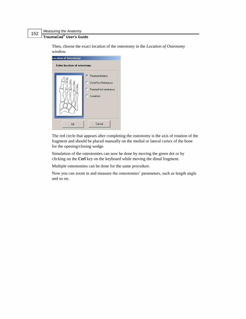
Measuring the Anatomy
TraumaCad® User's Guide
152
Then, choose the exact location of the osteotomy in the Location of Osteotomy
window.
The red circle that appears after completing the osteotomy is the axis of rotation of the
fragment and should be placed manually on the medial or lateral cortex of the bone
for the opening/closing wedge.
Simulation of the osteotomies can now be done by moving the green dot or by
clicking on the Ctrl key on the keyboard while moving the distal fragment.
Multiple osteotomies can be done for the same procedure.
Now you can zoom in and measure the osteotomies’ parameters, such as length angle
and so on.
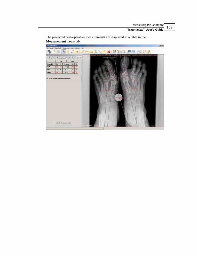
Measuring the Anatomy
TraumaCad® User's Guide
153
The projected post-operative measurements are displayed in a table in the
Measurement Tools tab.
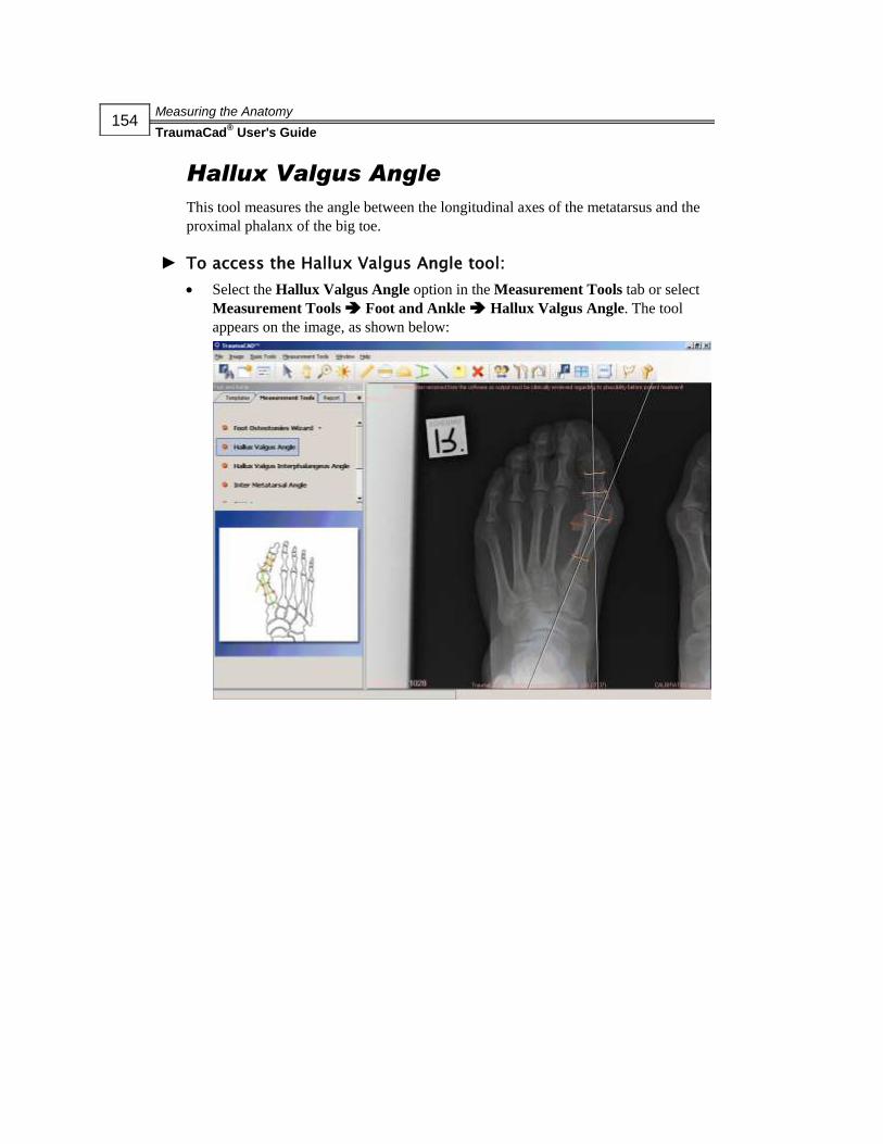
Measuring the Anatomy
TraumaCad® User's Guide
154
Hallux Valgus Angle
This tool measures the angle between the longitudinal axes of the metatarsus and the
proximal phalanx of the big toe.
► To access the Hallux Valgus Angle tool:
Select the Hallux Valgus Angle option in the Measurement Tools tab or select
Measurement Tools Foot and Ankle Hallux Valgus Angle. The tool
appears on the image, as shown below:

Measuring the Anatomy
TraumaCad® User's Guide
155
Hallux Valgus Interphalangeus Angle
This measurement tool measures the angle between the longitudinal axes of the
proximal phalanx and the middle phalanx of the big toe.
► To access the Hallux Valgus Interphalangeus Angle tool:
Select the Hallux Valgus Interphalangeus Angle option in the Measurement
Tools tab or select Measurement Tools Foot and Ankle Hallux Valgus
Interphalangeus Angle. The tool appears on the image, as shown below:

Measuring the Anatomy
TraumaCad® User's Guide
156
Intermetatarsal Angle
This measurement tool measures the angle between the longitudinal axes of the first
and second metatarsal bones.
► To access the Intermetatarsal Angle tool:
Select the Intermetatarsal Angle option in the Measurement Tools tab or select
Measurement Tools Foot and Ankle Intermetatarsal Angle. The tool
appears on the image, as shown below:

Measuring the Anatomy
TraumaCad® User's Guide
157
DMAA Distal Metatarsal Articular
Angle
This measurement tool measures the complement angle to 90 degrees of an angle
between the longitudinal axes of the first metatarsus to its distal articular surface.
► To access the Distal Metatarsal Articular Angle tool:
Select the Distal Metatarsal Articular Angle (DMAA) option in the
Measurement Tools tab or select Measurement Tools Foot and Ankle
Distal Metatarsal Articular Angle (DMAA). The tool appears on the image, as
shown below:

Measuring the Anatomy
TraumaCad® User's Guide
158
PMAA Proximal Metatarsal Articular
Angle
This measurement tool measures the complement angle to 90 degrees of an angle
between the longitudinal axes of the first metatarsus to its proximal articular surface.
► To access the Proximal Metatarsal Articular Angle tool:
Select the Proximal Metatarsal Articular Angle (PMAA) option in the
Measurement Tools tab or select Measurement Tools Foot and Ankle
Proximal Metatarsal Articular Angle (PMAA). The tool appears on the image,
as shown below:

Measuring the Anatomy
TraumaCad® User's Guide
159
Talar Tilt
This tool measures the angle between the ankle articular surfaces of the tibia and
talus.
► To access the Talar Tilt tool:
Select the Talar Tilt option in the Measurement Tools tab or select
Measurement Tools Foot and Ankle Talar Tilt. The tool appears on the
image, as shown below:

Measuring the Anatomy
TraumaCad® User's Guide
160
Upper Limb Measurements
The following upper limb measurements can be made using TraumaCad
measurements tools:
Center Line Finder, below
Simple Line, below
Joint Line, below
Center Line Finder
The Center Line Finder measurement tool is used for locating the center line of long
bones. Adjust the four points to the edges of the bone to display the center line. This
tool works as described in the Center Line Finder section on page 107. Consult this
section for more details.
► To access the upper limb Center Line Finder tool:
Select the Center Line Finder option in the Measurement Tools tab. The tool
appears on the image.
Simple Line
The Simple Line tool displays a line on the image that can be manipulated. If the line
crosses a second line, such as a Center line or Joint line, the angle between them is
calculated. This tool works as described in the Simple Line section on page 108.
Consult this section for more details.
► To access the upper limb Simple Line tool:
Select the Simple Line option in the Measurement Tools tab. The tool appears
on the image.

Measuring the Anatomy
TraumaCad® User's Guide
161
Joint Line
The Joint Line measurement tool enables you to select in advance the inclination,
location and orientation of the Joint line for various measurements, such as deformity
evaluation, joint replacement, preoperative planning and so on. This tool works as
described in the Joint Line section on page 161. Consult this section for more details.
► To access the upper limb Joint Line tool:
Select the Joint Line option in the Measurement Tools tab. The tool appears on
the image.
CORA Tools
Center Line Finder
The Center Line Finder measurement tool is used for locating the center line of long
bones. Adjust the four points to the edges of the bone to display the center line. This
tool works as described in the Center Line Finder section on page 107. Consult this
section for more details.
► To access the CORA Center Line Finder tool:
Select the CORA tools option in the Measurement Tools tab. The tool appears
on the image.
Joint Line
The Joint Line measurement tool enables you to select, in advance, the inclination,
location and orientation of the Joint line for various measurements, such as deformity
evaluation, joint replacement, preoperative planning and so on.
You can adjust the desired angle, as shown below:

Measuring the Anatomy
TraumaCad® User's Guide
162
You can also adjust its orientation (up-down) and direction (left-right):
You can also adjust the ratio between the two limbs of the joint line, as shown below:
► To access the CORA Joint Line tool:
Select the CORA tools option in the Measurement Tools tab. The tool appears
on the image.

Measuring the Anatomy
TraumaCad® User's Guide
163
Growth Calculator
You can select the Launch Growth Calculator option from the Measurements Tools
menu to display the following window:
Each tab of this window provides different options for predicting the growth of a
particular anatomy in pediatric orthopedics, as described below.
Begin by entering descriptive information about the patient, such as the patient’s
name, gender, date of birth and patient ID in the respective fields at the top of the
window. Then, select the appropriate tab in the window, input the required
information and click Answer.

Measuring the Anatomy
TraumaCad® User's Guide
164
The following buttons are available at the bottom of the window:
Saves Growth Calculator data to an *.XML file
Imports previously saved Growth Calculator data from an *.XML file
Saves Growth Calculator data to a *.CSV file
Prints Growth Calculator data
Displays Growth Calculator version information
Closes the Growth Calculator
Height Prediction Page
Purpose: Predicts the height of this patient at maturity.
Formula: Predicted Height = Current Height x Height Multiplier (specific for age and
sex, using a normal chart)
Leg Length Prediction Page
Purpose: Predicts leg length at maturity.
Formula: Predicted length at maturity = Current Length x Multiplier (specific for age
and sex, using a lower limb chart)
Growth remaining = Current length - predicted length
Arm Length Prediction Page
Purpose: Predicts the length of an arm at maturity.
Formula: Predicted length at maturity = Current Length x Multiplier (specific for age
and sex)
Growth remaining = Current length - predicted length
Leg Length Discrepancy Prediction -
Congenital Page
Purpose: Predicts the leg length discrepancy at maturity for this patient with
congenital LLD. (Congenital = congenital femoral deficiency, fibular hemimelia,
tibial hemimelia, hemihypertrophy, hemiatrophy, posteromedial bow of tibia)
Formula: Predicted length discrepancy at maturity = Current Length Discrepancy x
Multiplier (specific for age and sex, using a lower limb chart)

Measuring the Anatomy
TraumaCad® User's Guide
165
Leg Length Discrepancy Prediction -
Developmental Page
Purpose: Predicts the leg length discrepancy at maturity for this patient with
developmental LLD. (Developmental = Ollier’s, polio, growth arrest, also works for
congenital discrepancies after lengthening)
Formulas: Predicted length discrepancy at maturity = current difference + [1- (short
leg current - short leg previous)/ (long leg current - long leg previous)] x Long leg
current (Multiplier (specific for age and sex using a lower limb chart) -1)
Inhibition = 1- (short leg current - short leg previous)/ (long leg current - long leg
previous)
Arm Length Discrepancy Prediction -
Congenital Page
Purpose: Predicts arm length discrepancy at maturity for this patient with congenital
LLD. (Congenital = hemihypertrophy, hemiatrophy)
Formula: Predicted length discrepancy at maturity = Current Length Discrepancy x
Multiplier (specific for age and sex, using an upper limb chart)
Arm Length Discrepancy Prediction -
Developmental Page
Purpose: Predicts arm length discrepancy at maturity for this patient with
developmental LLD. (Developmental = Ollier’s, polio, growth arrest, also works for
congenital discrepancies after lengthening)
Formulas: Predicted length discrepancy at maturity = current difference + [1- (short
arm current - short arm previous)/ (long arm current - long arm previous)] x Long arm
current (Multiplier [specific for age and sex using upper limb chart] -1)
Inhibition = 1- (short arm current - short arm previous)/ (long arm current - long arm
previous)

Measuring the Anatomy
TraumaCad® User's Guide
166
Timing of Epiphyseodesis at the Knee
Page
Purpose: Suggests the timing for epiphyseodesis around the knee of a long limb to
equalize the limb length discrepancy at maturity.
Formulas: Multiplier at correct age for epiphyseodesis = [current long leg length x
current multiplier specific for age and sex using lower limb chart]/ (current long leg
length x current multiplier specific for age and sex using lower limb chart) - desired
correction / kappa
Kappa should be calculated for three scenarios: distal femur = 0.71,
Proximal tibia = 0.57, both distal femur and proximal tibia = 0.67
The resultant Multiplier at age correct for epiphyseodesis must be “translated” back to
a chronologic age using the lower extremity Multiplier chart specific for age and sex.
Timing of Stapling for Hemi-
epiphyseodesis Page
Purpose: Suggests the timing for hemi-epiphyseodesis around the knee to correct
angular deformities, if the staple will not be removed.
Formulas: Multiplier at correct age for hemi-epiphyseodesis = [current bone length x
current multiplier specific for age and sex using lower limb chart] / ([current bone
length x current multiplier specific for age and sex using lower limb chart] - [(width
of the growth plate x desired correction/57) / kappa]
Kappa should be calculated for one of two scenarios: distal femur = 0.71, proximal
tibia = 0.57
The resultant Multiplier at age correct for hemi-epiphyseodesis must be “translated”
back to a chronologic age using the lower extremity Multiplier chart specific for age
and sex.

Measuring the Anatomy
TraumaCad® User's Guide
167
Timing of Staple Removal for
Hemi-epiphyseodesis Page
Purpose: Suggests the timing for removing a staple inserted for hemi-epiphyseodesis
around the knee to correct angular deformities, assuming that the stapling was done
well prior to skeletal maturity.
Formulas: Multiplier at correct age for removal of hemi-epiphyseodesis staple =
[current bone length x current multiplier specific for age and sex using lower limb
chart] / ([current bone leg length + [(width of the growth plate x desired
correction/57)/ kappa]
Kappa should be calculated for one of two scenarios: distal femur = 0.71, Proximal
tibia = 0.57
The resultant Multiplier at age for removal of hemi-epiphyseodesis staple must be
“translated” back to a chronologic age using the lower extremity Multiplier chart
specific for age and sex.
CDC Growth Charts
The growth charts consist of a series of percentile curves that illustrate the distribution
of selected body measurements in children in the United States. The 1977 growth
charts were developed by the National Center for Health Statistics (NCHS) as a
clinical tool for health professionals to determine if the growth of a child is adequate.
The 1977 charts were also adopted by the World Health Organization for international
use.
When the 1977 NCHS growth charts were first developed, NCHS recommended that
they be revised periodically, as necessary. With more recent and comprehensive
national data now available, along with improved statistical procedures, the 1977
growth charts have been revised and updated to make them a more valuable clinical
tool for health professionals.
The 2000 CDC growth charts represent the revised version of the 1977 NCHS growth
charts. Most of the data used to construct these charts come from the National Health
and Nutrition Examination Survey (NHANES), which has periodically collected
height, weight and other health information about the American population since the
early 1960s.

Measuring the Anatomy
TraumaCad® User's Guide
168
This page is intentionally left blank.

Reports
TraumaCad® User's Guide
169
Chapter 5
Reports
NOTE:
Procedures and sections in the guide are marked to indicate whether they apply to
standalone mode ( ) or web client mode ( ).
Generating Reports
A report consists of the selected images with templates or measurements that were
added and textual information describing the patient, the measurements, the surgical
procedure to be performed and/or the implant to be used and any text that the surgeon
chooses to add.
WARNING!
The material generated by the program is two dimensional. Before performing a
procedure, confirm that the actual bone matches the image produced by the software.

Reports
TraumaCad® User's Guide
170
An example of an HTML report is shown below. It can be saved locally, printed,
commited to PACS, uploaded to Orthoweb or sent to OrthoFlow for future reference.

Reports
TraumaCad® User's Guide
171
► To generate a report:
Select the Report tab. The following is then displayed:
The following report options are provided:
Original Image: Specifies that the original image is included in the report.
Templated Image: Specifies that the image after templating in TraumaCad is
included in the report.
Comments: Adds specific user comments to the report.
: Displays an HTML report. You should save this report or print it
before opening another case study.
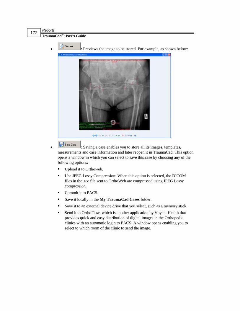
Reports
TraumaCad® User's Guide
172
: Previews the image to be stored. For example, as shown below:
: Saving a case enables you to store all its images, templates,
measurements and case information and later reopen it in TraumaCad. This option
opens a window in which you can select to save this case by choosing any of the
following options:
Upload it to Orthoweb.
Use JPEG Lossy Compression: When this option is selected, the DICOM
files in the .tcc file sent to OrthoWeb are compressed using JPEG Lossy
compression.
Commit it to PACS.
Save it locally in the My TraumaCad Cases folder.
Save it to an external device drive that you select, such as a memory stick.
Send it to OrthoFlow, which is another application by Voyant Health that
provides quick and easy distribution of digital images in the Orthopedic
clinics with an automatic login to PACS. A window opens enabling you to
select to which room of the clinic to send the image.

Installing TraumaCad
TraumaCad® User's Guide
173
Appendix A
Installing TraumaCad
NOTE:
Procedures and sections in the guide are marked to indicate whether they apply to
standalone mode ( ) or web client mode ( ).
Installation of TraumaCad must be performed on a computer that is connected to the Web. TraumaCad can be installed from either a CD or downloaded from
Voyant Health’s website.
NOTE:
For standalone versions of TraumaCad, the PACS configuration must first be set up in
order to specify the connection properties between TraumaCad and the PACS system.
Typically, this only needs to be performed once by a system administrator after the initial
installation of TraumaCad. The system administrator should make sure to enter the
relevant connection properties in the PACS system so that it recognizes TraumaCad.
For more information, see page 180.
Installing TraumaCad
Installation of TraumaCad must be performed on a computer that is connected to the Web. TraumaCad can be installed from either a CD or downloaded from
Voyant Health’s website at www.voyanthealth.com.
NOTE:
After installation and the first launch, TraumaCad does not need to be connected to the
Web.

Installing TraumaCad
TraumaCad® User's Guide
174
Installing from a CD
If you are installing from a CD, the following window is displayed automatically:
Click on Install TraumaCad.
Installing via the Web
If you are installing via the Web, launch Internet Explorer and enter the URL of the
organization’s server that runs TraumaCad Server. The following window is
displayed:
Click Start Here and when asked whether to run or save the program, select Run.
Then, follow the procedure described below.

Installing TraumaCad
TraumaCad™ User's Guide
175
How to Install TraumaCad
The TraumaCad installation program will check if Windows.Net is installed on your
computer. If not, it will download and install it. You are then required to restart your
computer. If you are installing from a CD, do not remove it from the drive.
► To install TraumaCad:
1 The Welcome window is displayed, as shown below:
The License Agreement window is displayed:
Read the agreement, select
this button and click Next
Click Next
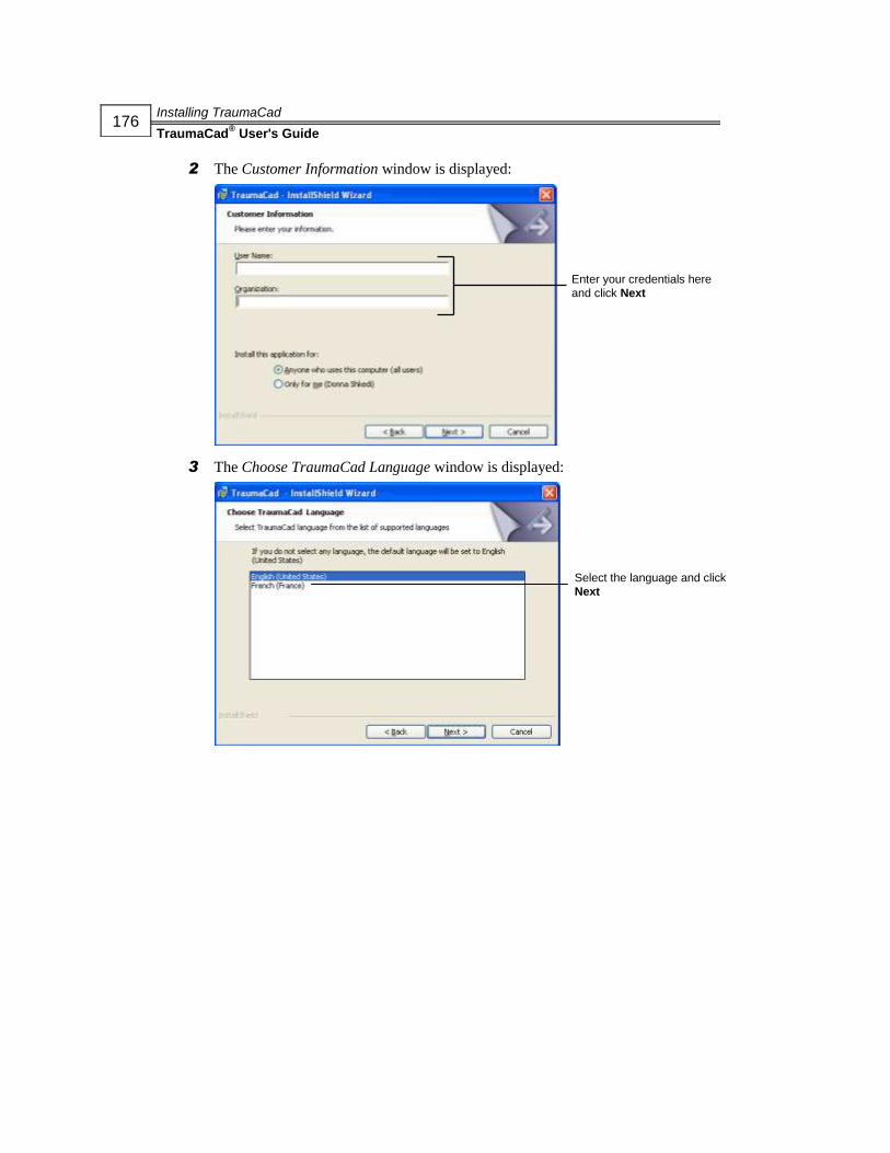
Installing TraumaCad
TraumaCad® User's Guide
176
2 The Customer Information window is displayed:
3 The Choose TraumaCad Language window is displayed:
Enter your credentials here
and click Next
Select the language and click
Next
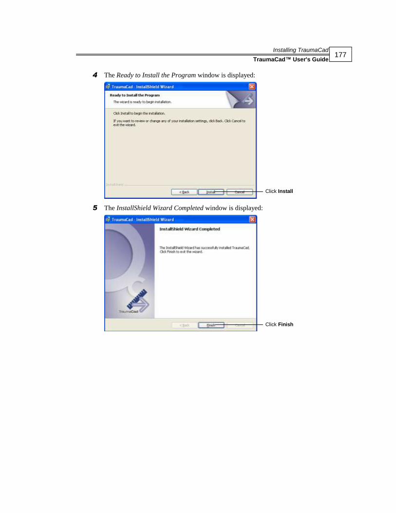
Installing TraumaCad
TraumaCad™ User's Guide
177
4 The Ready to Install the Program window is displayed:
5 The InstallShield Wizard Completed window is displayed:
Click Install
Click Finish

Installing TraumaCad
TraumaCad® User's Guide
178
This page is intentionally left blank.

Standalone Usage
TraumaCad™ User's Guide
179
Appendix B
Standalone Usage
NOTE:
Procedures and sections in the guide are marked to indicate whether they apply to
standalone mode ( ) or web client mode ( ).
This appendix describes several procedures that may be required in standalone mode,
as follows:
Setting the PACS Configuration, page 180
Importing Images from a CD, page 181
Capturing Images from the Screen, page 182

Standalone Usage
TraumaCad® User's Guide
180
Setting the PACS Configuration
(Optional)
This optional step only applies to standalone versions of TraumaCad. It enables you to
specify the connection properties between TraumaCad and the PACS system.
Typically, this only needs to be performed once by a system administrator after the
initial installation of TraumaCad. The system administrator should make sure to enter
the relevant connection properties in the PACS system so that it recognizes
TraumaCad.
NOTE:
Client/Server versions of TraumaCad can skip this step since it is performed on the server,
as described in the TraumaCad Adminstrator’s Guide.
► To set up the PACS Configuration:
1 In the menu bar, select File PACS Configuration. The PACS Configuration
window is displayed:
2 Enter the relevant PACS connection information into the appropriate fields. This
information should be available to your network administrator.
3 Click OK to save and apply these settings.

Standalone Usage
TraumaCad™ User's Guide
181
Importing Images from a CD
On the standalone version of TraumaCad, two options are provided for importing
images into your local cache on your local computer. You can then commit these to
the PACS system if you like. These are:
Import DICOM Folder
Import Image: Imports a single image file that is a JPG, DICOM or another file
format. A window is displayed in which you can enter the information about this
image that will be stored with it.
WARNING!
When importing an image or using an image from the local cache, make sure that
you import data from the correct patient, and use the correct image from the correct
patient.
NOTE:
Select File Delete Cache to clear the cache of images on your local computer.

Standalone Usage
TraumaCad® User's Guide
182
Capturing Images from the Screen
Select the Screen Capture option in the File menu to capture any image that is
displayed on the screen into TraumaCad. The following window is displayed:
Drag the Finder Tool over the image to be captured. It is then added to
TraumaCad, and you can later commit it to PACS if you like.
Managing Implant Templates
TraumaCad® User's Guide
183
Appendix C
Managing Implant
Templates TraumaCad provides a large library of digital templates for a wide variety of
orthopedic surgical procedures.
For the server version of TraumaCad, these implant images are automatically
imported and updated on your computer from the TraumaCad server.
For the standalone version of TraumaCad, select File Download Templates in the
menu bar to download templates of implants from Voyant Health’s global repository
to your computer.
Each implant is provided in a variety of sizes and properties and each such group is
called an implant template. Several implanting scenarios can be recorded and
compared to find the optimal implant procedure. Once an implant is chosen, it can
easily be scaled and manipulated.

Managing Implant Templates
TraumaCad® User's Guide
184
Importing Implant Templates
Before TraumaCad is used for the first time, the implant templates should be
imported. This procedure should also be performed from time to time to update the
template library.
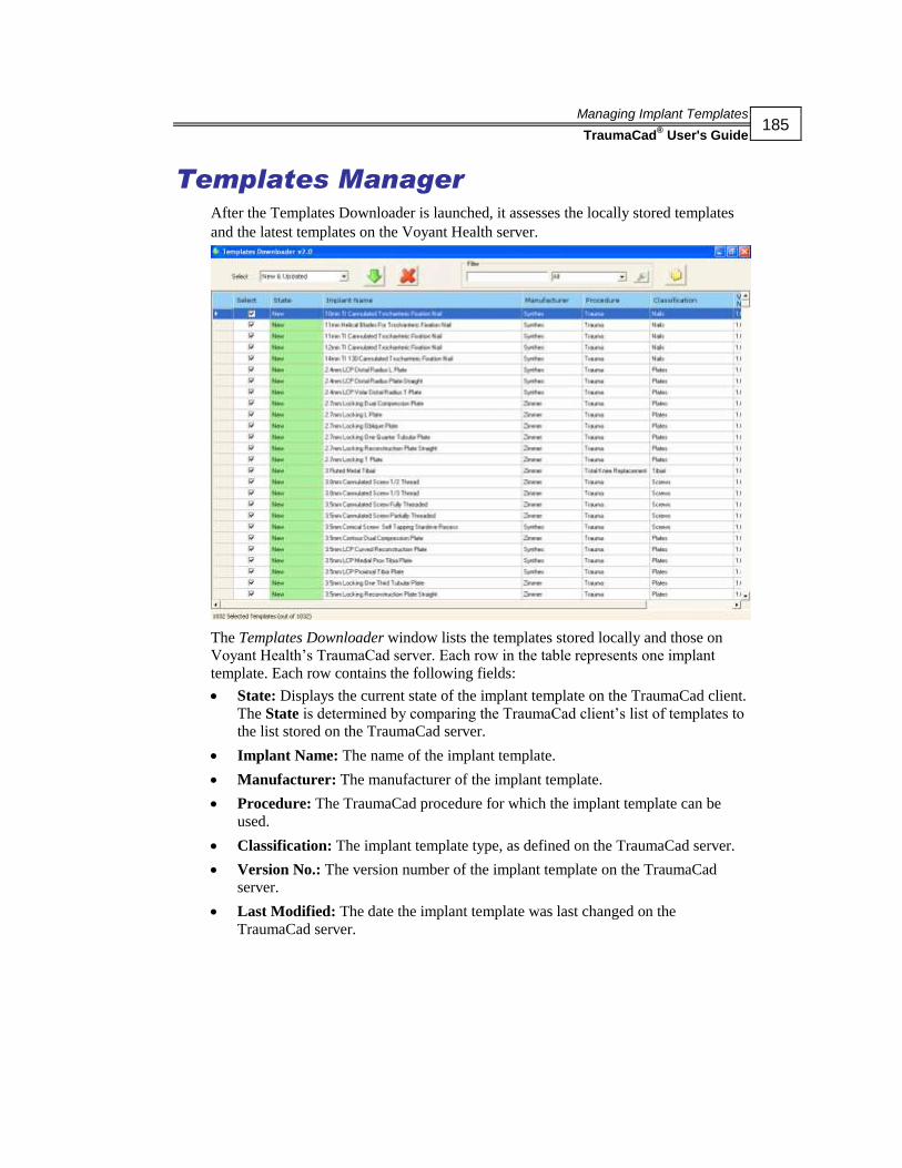
Managing Implant Templates
TraumaCad® User's Guide
185
Templates Manager After the Templates Downloader is launched, it assesses the locally stored templates
and the latest templates on the Voyant Health server.
The Templates Downloader window lists the templates stored locally and those on
Voyant Health’s TraumaCad server. Each row in the table represents one implant
template. Each row contains the following fields:
State: Displays the current state of the implant template on the TraumaCad client.
The State is determined by comparing the TraumaCad client’s list of templates to
the list stored on the TraumaCad server.
Implant Name: The name of the implant template.
Manufacturer: The manufacturer of the implant template.
Procedure: The TraumaCad procedure for which the implant template can be
used.
Classification: The implant template type, as defined on the TraumaCad server.
Version No.: The version number of the implant template on the TraumaCad
server.
Last Modified: The date the implant template was last changed on the
TraumaCad server.

Managing Implant Templates
TraumaCad® User's Guide
186
In the Select dropdown list, you can specify whether you want to choose all or some
implant templates. Whichever option you select automatically checks the checkboxes
of the corresponding implant templates in the table. The available options are:
New & Updated: Selects implant templates that are either new to or that have
been updated on the TraumaCad server. This is the default.
New: Selects implant templates that exist on the TraumaCad server, but that do
not exist on the local TraumaCad client.
Updated: Selects implant templates that have been updated on the TraumaCad
server. A newer version of this template exists on the server.
Existing: Selects implant templates that currently exist on the TraumaCad client.
This means that the latest version of the template already exists on the local client.
All: Selects all implant templates in the table.
None: Selects no implant templates in the table.
You can also select a specific implant template(s) by selecting its respective checkbox
in the Select column of the table.
► To download templates to the local client:
1 Select the required templates by clicking the checkbox to the left of the template
name or by selecting the relevant option in the Select dropdown list.
2 Click the Download Selected Templates button to start downloading the
selected templates.

Managing Implant Templates
TraumaCad® User's Guide
187
Other Templates Manager Options
The following other options are available in this window:
Searching for Templates
You can search for specific templates (meaning, filter the list of templates) by
entering text, such as the template name or part of the name in the Filter area and
clicking the Search Templates button to its right. You should then select one of
the options from the dropdown menu in the right field in the Filter area to specify
whether this text appears anywhere in the template information, in the State column,
Implant Name column, Manufacturer column, Procedure column, Classification
column or Version No: column.
Remove Selected Templates
Select the required templates by clicking the checkbox to the left of the template name
and then click the Remove Selected Templates button to delete the implant
template from the local TraumaCad client.
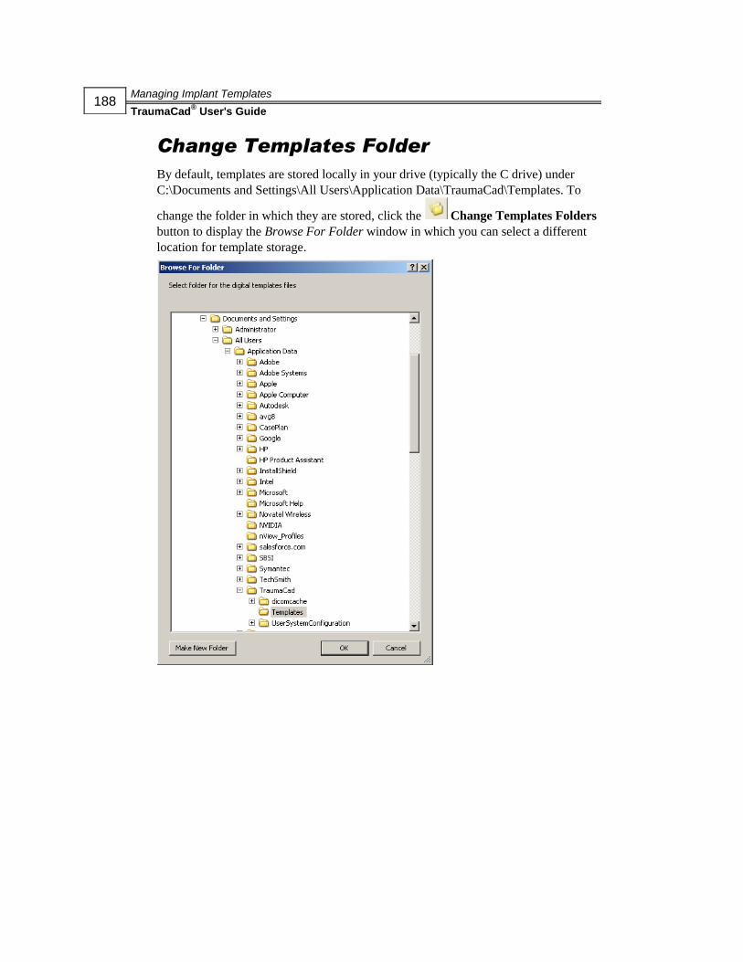
Managing Implant Templates
TraumaCad® User's Guide
188
Change Templates Folder
By default, templates are stored locally in your drive (typically the C drive) under
C:\Documents and Settings\All Users\Application Data\TraumaCad\Templates. To
change the folder in which they are stored, click the Change Templates Folders
button to display the Browse For Folder window in which you can select a different
location for template storage.

Index
TraumaCad® User's Guide
189
Index
3
3D Suite, 61
Adding a 3D Template, 66
Implant Navigation Window, 68
MIP View, 65
MPR View, 63
Opening a 3D Image, 62
3D Templates, 66
A
Acetabular Index, 101, 117
Anatomical Orientation, 30
Angle Tool, 73
Archiving, 4
Articulo-trochanteric Distance, 122
Auto-Hip, 77
Automatic Procedures, 9
B
Bone Fragments
Defining, 54
Lassoing, 55
Reducing, 53
C
Calibration
Copying Data, 38
Images, 3, 31, 34, 36
Calibration Sphere, 32
Calibration Window, 34
Capturing
Images, 180
Center Line Finder, 107, 128, 158, 159
Center of Rotation, 104
Circle Tool, 73
Client/Server, 5
Client/Server Functionality, 5
Cobb Angle, 134
Compressing
Images, 28
Contacting Us, x
Copying
Calibration Data, 38
CORA Tools, 85, 159
Center Line Finder, 159
Joint Line, 159
Coronal Balance, 138
Cup Version, 103
D
Defining
Bone Fragments, 54
Deformity, 69
Diaphyseal Fracture Angulation, 127
Displaying the Image, 3
Distal Metatarsal Articular Angle, 155
Double Cobb Angle, 135
E
Epiphyseal Index, 123

Index
TraumaCad® User's Guide
190
F
Finding Patients, 26
Foot and Ankle Tools, 146
Distal Metatarsal Articular Angle, 155
Foot Osteotomies Simulation, 149
Foot Osteotomies Wizard, 146
Hallux Valgus Angle, 152
Hallux Valgus Interphalangeus Angle,
153
Intermetatarsal Angle, 154
Proximal Metatarsal Articular Angle,
156
Talar Tilt, 157
Foot Osteotomies Simulation, 149
Foot Osteotomies Wizard, 146
FreehandLine Tool, 75
G
Generating Reports, 167
Generic Tools, 72
Grouping
Objects, 24
Templates, 57
Growth Calculator, 161
H
Hallux Valgus Angle, 152
Hallux Valgus Interphalangeus Angle,
153
Head Shaft (Slip) Angle, 121
High Tibial Osteotomy, 109
Hip
Auto, 77
Hip Deformity Analysis, 95, 112
Hip Measurements, 94
Acetabular Index, 101
Center of Rotation, 104
Cup Version, 103
Hip Deformity Analysis, 95
Leg Length Discrepancy Tool, 100
Stem Version, 105
VCA Angle of Lequesne, 102
I
Images
Calibrating, 31, 34, 36
Capturing from the Screen, 180
Compressing, 28
Importing from CD, 179
Loading from PACS, 26
Preparing, 25
Selecting, 27
Implant Navigation Window, 68
Implant Templates, 181
Changing Default Folder, 186
Importing, 182
Removing, 185
Searching For, 185
Importing
Digital X-rays, 3
Images from CD, 179
Installing
TraumaCad, 171, 173
TraumaCad from a CD, 172
TraumaCad via the Web, 172
Interline Tool, 74
Intermetatarsal Angle, 154
J
Joint Line, 111, 130, 158, 159
K
Kit, 42
Knee Measurements, 106
Center Line Finder, 107
High Tibial Osteotomy, 109
Joint Line, 111
Simple Line, 108
Tibial Cutting, 110

Index
TraumaCad® User's Guide
191
L
Lassoing
Bone Fragments, 55
Launching
TraumaCad, 7
Leg Length Discrepancy Tool, 100
Limb Alignment Analysis, 80, 126
Marking Anatomical Points, 81
Unilateral, 82
Line Tool, 74
Local Cases, 12
Locking Compresion Plates, 59
Lumbar Lordosis Angle, 144
M
Manual Procedures, 9
Marking Anatomical Points, 81
Measuring the Anatomy, 71
Menu Bar, 15
Metaphyseal Fracture Angulation, 128
Metaphyseal-Diaphyseal Angle, 125
MIP View, 65
MPR View, 63
Multiple Views, 31
My Local Cases, 12
N
Neck Shaft Angle, 120
News, 13
O
Opening a 3D Image, 62
Original Images Folder, 12
OrthoMark, 33
OrthoWeb
Account, 11
Cases, 10
P
PACS Configuration, 178
Pediatric Measurements, 112
Acetabular Index, 117
Articulo-trochanteric Distance, 122
Epiphyseal Index, 123
Head Shaft (Slip) Angle, 121
Hip Deformity Analysis, 112
Metaphyseal-Diaphyseal Angle, 125
Neck Shaft Angle, 120
Reimer’s Index, 118
Tibiofemoral Angle, 124
VCA Angle of Lequesne, 119
Pelvic Radius Angle, 135
Performing
Pre-operative Planning, 4
Plate Bending, 56
Positioning
Implants, 49
Pre-operative Planning, 4
Preparing the Image, 25
Proximal Metatarsal Articular Angle, 156
Q
Quick Tour, 14
R
Reducing
Bone Fragments, 53
Reimer’s Index, 118
Remove Marker after calibration, 35
Reports, 167
Resources Folder, 12
Right-click Menus, 23
Roof Arc, 129
Ruler Tool, 72

Index
TraumaCad® User's Guide
192
S
Sacral Obliquity, 137
Safety Symbols, xi
Sagittal Balance, 139
Scaling
X-rays, 32
Selecting
Implants, 44
Patient Images, 27
TraumaCad Procedure, 3
Simple Line, 108, 129, 158
Specifying
Anatomical Orientation, 3, 30
Anatomical Region, 51
Implant Properties, 47
Spine Measurements, 131
Cobb Angle, 134
Coronal Balance, 138
Double Cobb Angle, 135
Lumbar Lordosis Angle, 144
Pelvic Radius Angle, 135
Sacral Obliquity, 137
Sagittal Balance, 139
Spine Slip Angle, 145
Spondylolysthesis, 140
T1 Tilt Angle, 143
Thoracic Kyphosis Angle, 141
Thoracic Trunk Shift, 142
Triple Cobb Angle, 135
Vertebrae Labeling, 131
Spine Slip Angle, 145
Spondylolysthesis, 140
Standalone Functionality, 5
Stem Version, 105
System Requirements, 6
T
T1 Tilt Angle, 143
Talar Tilt, 157
tcc, 13
Template Features
Grouping, 57
Locking Compression Plates, 59
Plate Bending, 56
Templated Images Folder, 12
Templates, 56
Kit, 42
Templates Manager, 183
Changing Templates Folder, 186
Removing Templates, 185
Searching for Templates, 185
Templating, 43
Positioning an Implant, 49
Selecting an Implant, 44
Specifying Implant Properties, 47
Text Annotations, 76
Thoracic Kyphosis Angle, 141
Thoracic Trunk Shift, 142
Tibial Cutting, 110
Tibiofemoral Angle, 124
Toolbar, 19
Trauma Measurements, 126
Center Line Finder, 128
Diaphyseal Fracture Angulation, 127
Joint Line, 130
Limb Alignment Analysis, 126
Metaphyseal Fracture Angulation, 128
Roof Arc, 129
Simple Line, 129
TraumaCad
Client/Server, 5
Generic Tools, 72
Getting Started, 1
Implant Templates, 181
Importing Digital X-ray, 3
Installing, 171
Launching, 7
Menu Bar, 15
PACS Configuration, 178
Procedures, 39, 50
Quick Tour, 14

Index
TraumaCad® User's Guide
193
Right-click Menus, 23
Selecting Procedure, 3
Specifying Anatomical Orientation, 3
Standalone, 5
Standalong Usage, 177
System Requirements, 6
Template Features, 56
Templating, 43
Toolbar, 19
Using, 2
Workflow, 2
Triple Cobb Angle, 135
U
Unilateral Measurements, 82
Upper Limb Measurements, 158
Center Line Finder, 158
Joint Line, 158
Simple Line, 158
V
VCA Angle of Lequesne, 102, 119
Vertebrae Labeling, 131
X
X-rays
Scaling, 32

Index
TraumaCad® User's Guide
194
This page is intentionally left blank.