traxess rrv access system - thomson rail sheets/trx13-inst-01 operator... · 4 transport and...
TRANSCRIPT

Copyright: Th omson Engineering Design Ltd all rights reservedDocument Number:TRX-Inst-01 Issue: 01 Date: April 2013
Traxess RRV Access System
User and Maintenance Training Instructions for the Thomson Engineering Design Ltd Traxess on and off-
tracking system for Road Rail Vehicles up to 30 tonnes.
Issue 1 March 2013

2
Introduction
Th is manual is designed to form the basis of a training course in the safe use and maintenance of the Th omson Engineering Design Ltd Traxess temporary on and off -tracking system.
A short pictorial user instruction sheet is also provided with Traxess systems for use by personnel who have been trained according to this instruction.
When properly installed the Traxess system provides a safe, reliable on tracking point for use by both wheeled and tracked Road Rail Vehicles (RRV’s) up to 30 tonnes in weight.
Traxess systems are manufactured in the United Kingdom by:
Thomson Engineering Design LtdValley RoadCinderfordGloucestershireGL14 2NZ
Tel: +44 (0) 1594 82 66 11Fax: +44 (0) 1594 82 55 60Email: [email protected]
Th e manufacturer can provide product familiarisation training for qualifi ed training centres.
It is vitally important for the safety of all concerned that the procedures described in this manual are fully understood. If any part of this manual seems unclear or if any issues arise which are not covered by this manual please contact the manufacturer.
Traxesss System installed at Hoo Junction Yard
3
Specifi cations
Th e following specifi cations are for a typical Traxess system however there are a number of diff erent confi gurations available so for accurate weights and dimensions please check the manufacturer’s plates attached to the individual system components.
Traxess is designed to allow the passage of rail traffi c and does not interfere with normal running gauge clearances. It is recommended however that rail traffi c does not exceed 20 mph when passing over the traxess system.
Total System Weight 4,280 kgS llage Tare Weight 340 kgSide Panel Weight (each) 970 kgCentre Panel Weight 2,000 kg
Maximum Safe Working Load (WLL) 30,000 kgDeck Height (above rail head BS113a) 35 mm
All parts of the Traxess system are fi tted with integral lift ing points so that the system can be easily installed using a Road Rail Excavator.
Warning
Before attempting to lift the Traxess system stillage or any of the parts of the Traxess system, carefully plan the lift with reference to the lift ing machine’s duty chart.
All lift ing operations should be properly planned and carried out under the supervision of properly trained and competent personnel.
4
Transport and Handling
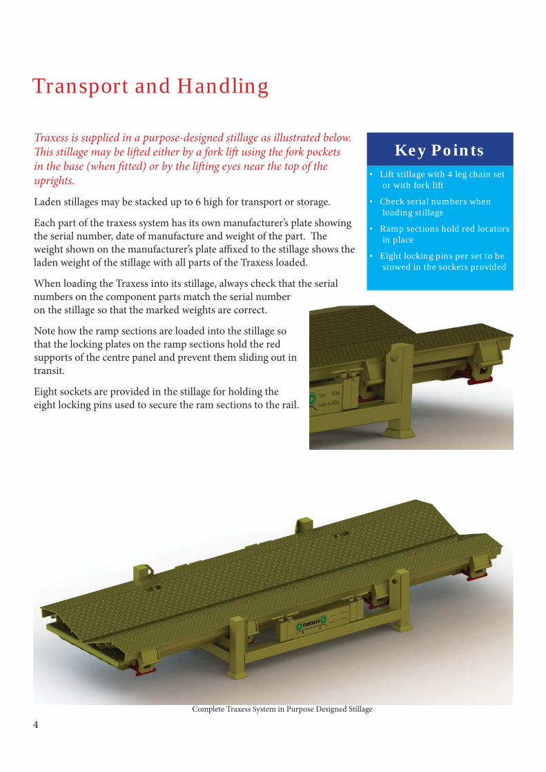
Traxess is supplied in a purpose-designed stillage as illustrated below. Th is stillage may be lift ed either by a fork lift using the fork pockets in the base (when fi tted) or by the lift ing eyes near the top of the uprights.
Laden stillages may be stacked up to 6 high for transport or storage.
Each part of the traxess system has its own manufacturer’s plate showing the serial number, date of manufacture and weight of the part. Th e weight shown on the manufacturer’s plate affi xed to the stillage shows the laden weight of the stillage with all parts of the Traxess loaded.
When loading the Traxess into its stillage, always check that the serial numbers on the component parts match the serial number on the stillage so that the marked weights are correct.
Note how the ramp sections are loaded into the stillage so that the locking plates on the ramp sections hold the red supports of the centre panel and prevent them sliding out in transit.
Eight sockets are provided in the stillage for holding the eight locking pins used to secure the ram sections to the rail.
Complete Traxess System in Purpose Designed Stillage
Key Points• Lift stillage with 4 leg chain set
or with fork lift
• Check serial numbers when loading stillage
• Ramp sections hold red locators in place
• Eight locking pins per set to be stowed in the sockets provided
5
Installation
Fitting the Traxess system to the rail should take no more than ten to fi ft een minutes in normal circumstances.
An RRV is used to carry out all the lift ing operations. Each lift ing operation should be planned with due regard to the ground conditions and the duty chart of the RRV.
Beware of overhead electrical and signalling equipment when installing and removing Traxess.
Preparing the Site
Ballast shoulders and crib ballast should not be higher than the top face of the sleepers in the area where Traxess is to be installed and loose ballast should be removed from the foot of the rail.
Traxess can be fi tted on track with 28, 30 or 32 sleepers per length. If possible choose areas of track which are straight and level to give the safest on-tracking.
Ideally, Traxess should not be fi tted over fi sh plates. Traxess MUST NOT be fi tted over insulated block joints.
Place the Traxess stillage as close as reasonably practicable to the track to minimise the time taken to install it.
Li ing the Traxess Panels
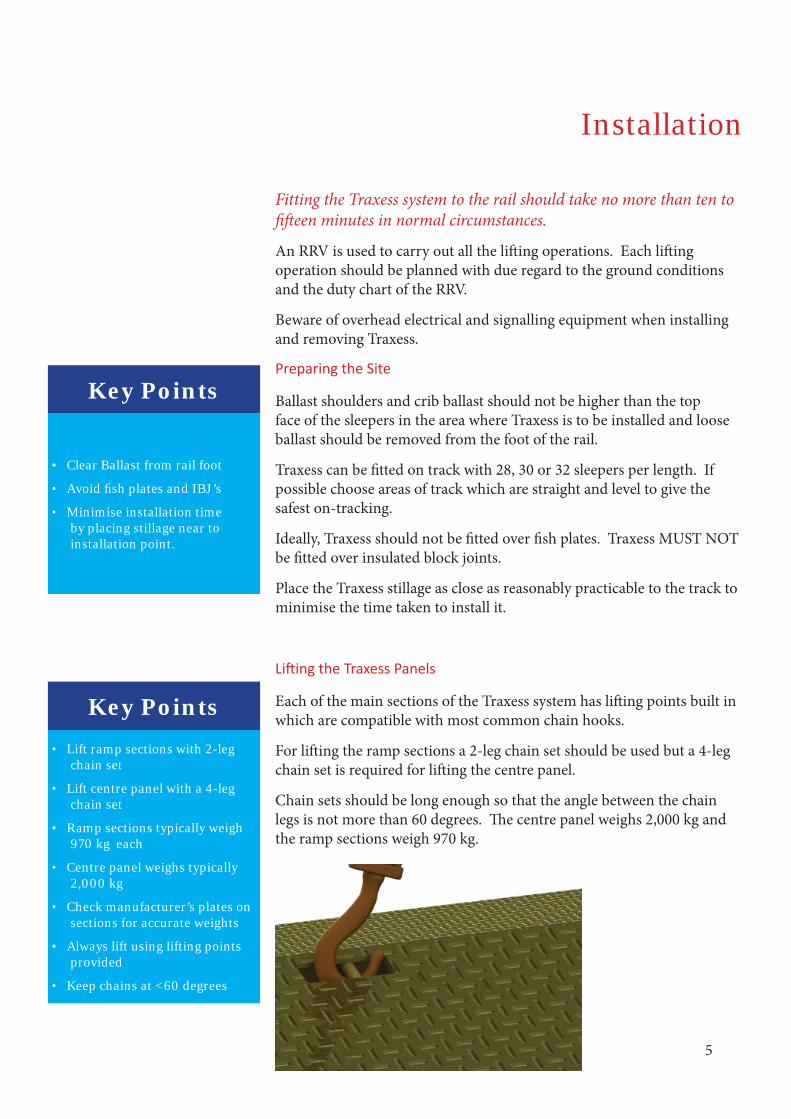
Each of the main sections of the Traxess system has lift ing points built in which are compatible with most common chain hooks.
For lift ing the ramp sections a 2-leg chain set should be used but a 4-leg chain set is required for lift ing the centre panel.
Chain sets should be long enough so that the angle between the chain legs is not more than 60 degrees. Th e centre panel weighs 2,000 kg and the ramp sections weigh 970 kg.
Key Points• Lift ramp sections with 2-leg
chain set
• Lift centre panel with a 4-leg chain set
• Ramp sections typically weigh 970 kg each
• Centre panel weighs typically 2,000 kg
• Check manufacturer’s plates on sections for accurate weights
• Always lift using lifting points provided
• Keep chains at <60 degrees
Key Points
• Clear Ballast from rail foot
• Avoid fi sh plates and IBJ’s
• Minimise installation time by placing stillage near to installation point.
6
Fit the First Ramp Section
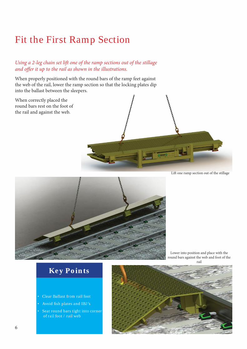
Using a 2-leg chain set lift one of the ramp sections out of the stillage and off er it up to the rail as shown in the illustrations.
When properly positioned with the round bars of the ramp feet against the web of the rail, lower the ramp section so that the locking plates dip into the ballast between the sleepers.
When correctly placed the round bars rest on the foot of the rail and against the web.
Lift one ramp section out of the stillage
Lower into position and place with the round bars against the web and foot of the
rail
Key Points
• Clear Ballast from rail foot
• Avoid fi sh plates and IBJ’s
• Seat round bars tight into corner of rail foot / rail web

7
Lock the Ramp Section
Lock the ramp section into place using 4 of the locking pins from the sockets on one side of the stillage.
With the handle upright, push the pin under the foot of the rail so that the end of the pin passes through the rectangular hole in the ramp section locking plate.
Turn the handle to the horizontal position to lock the pin. Fit the other three pins to secure the ramp section.
Push the locking pin under the rail foot and through the rectangular hole in the locking plate. Th e angle plate on
the pin collar hooks onto the edge of the rail foot.
Turn the handle to the horizontal position to lock the pin in place. Fit the other three
pins to secure the ramp section.
Key Points
• Hold handle upright when inserting pin
• Turn handle horizontal to lock pin in place
Tip• Pins will not fi t unless side
panels are fi rmly resting in corner of rail web/foot

8
Fit the Second Ramp Section
Repeat the instructions above to install the second ramp section on the other side of the track.
Remember to fi t all four pins in this section as well.
Take care to ensure that, when reaching over the track, the RRV has suffi cient load capacity at the required radius.
Key Points
• Clear Ballast from rail foot
• Avoid fi sh plates and IBJ’s
• Check that all 4 pins are fi tted to each ramp section
Alternative Layouts
Traxess will normally be laid out with the panels aligned but they may be off set where RRV’s must cross a line to reach another line as in the example illustrated below.
When laying out Traxess in an off set confi guration take care to ensure that the red support legs are between sleepers and not in contact with clips or clip housings.
Key Points• Support legs must be between
sleepers to protect clips
9
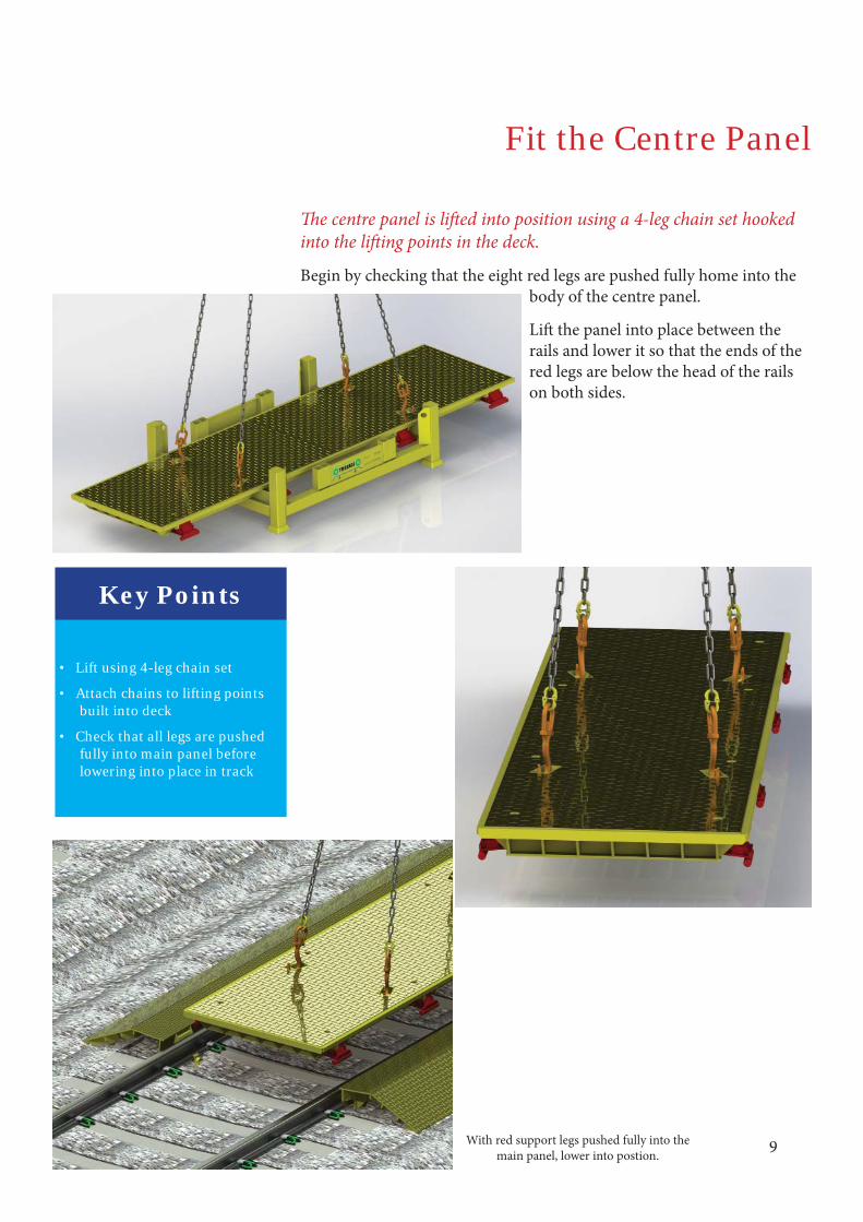
Fit the Centre Panel
Th e centre panel is lift ed into position using a 4-leg chain set hooked into the lift ing points in the deck.
Begin by checking that the eight red legs are pushed fully home into the body of the centre panel.
Lift the panel into place between the rails and lower it so that the ends of the red legs are below the head of the rails on both sides.
Key Points
• Lift using 4-leg chain set
• Attach chains to lifting points built into deck
• Check that all legs are pushed fully into main panel before lowering into place in track
With red support legs pushed fully into the main panel, lower into postion.
10
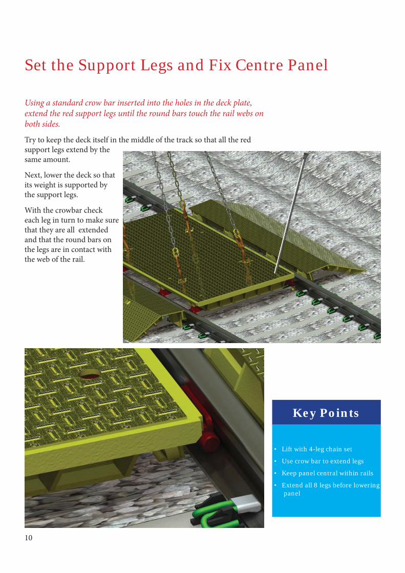
Set the Support Legs and Fix Centre Panel
Using a standard crow bar inserted into the holes in the deck plate, extend the red support legs until the round bars touch the rail webs on both sides.
Try to keep the deck itself in the middle of the track so that all the red support legs extend by the same amount.
Next, lower the deck so that its weight is supported by the support legs.
With the crowbar check each leg in turn to make sure that they are all extended and that the round bars on the legs are in contact with the web of the rail.
Key Points
• Lift with 4-leg chain set
• Use crow bar to extend legs
• Keep panel central within rails
• Extend all 8 legs before lowering panel

11
Check the Centre Panel is Central & Secure
Check that all eight of the red support legs are evenly extended. Use the crowbar through the holes in the decking to adjust them if necessary.
When correctly fi tted there should be approximately 5mm of the top plate of each support leg visible beyond the yellow edge strip of the body.
Once this is checked the chains can be removed and the Traxess is ready for use.
Key Points
• Red support legs should be extended the same amount both sides
• Approximately 5mm of the top red plate should be visible
When correctly fi tted approximately 5mm of the red top plate is visible (top circle) and the centre panel rests on the diagonal blocks welded to the sides of the red support legs (lower circle).
12
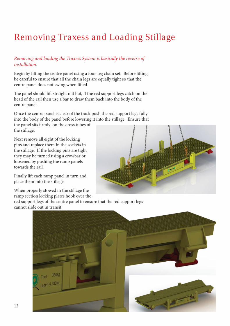
Removing Traxess and Loading Stillage
Removing and loading the Traxess System is basically the reverse of installation.
Begin by lift ing the centre panel using a four-leg chain set. Before lift ing be careful to ensure that all the chain legs are equally tight so that the centre panel does not swing when lift ed.
Th e panel should lift straight out but, if the red support legs catch on the head of the rail then use a bar to draw them back into the body of the centre panel.
Once the centre panel is clear of the track push the red support legs fully into the body of the panel before lowering it into the stillage. Ensure that the panel sits fi rmly on the cross tubes of the stillage.
Next remove all eight of the locking pins and replace them in the sockets in the stillage. If the locking pins are tight they may be turned using a crowbar or loosened by pushing the ramp panels towards the rail.
Finally lift each ramp panel in turn and place them into the stillage.
When properly stowed in the stillage the ramp section locking plates hook over the red support legs of the centre panel to ensure that the red support legs cannot slide out in transit.

13
Certifi cate of Conformity
We:
Thomson Engineering Design Ltd
Valley RoadCinderfordGloucestershireGL14 2NZ
Declare under our sole responsibility that the product known as:
Traxess System
To which this declaration relates is in conformity with the following standards:
2006/42/EC
Authorised signatory:
David Th omson BSc
March 2013
Th omson Engineering Design Ltd. Valley Road, Cinderford, Gloucestershire. GL14 2NZTel: +44 (0) 1594 82 66 11 Fax: +44 (0) 1594 82 55 60 Email: [email protected]