trbonet cp deployment guides3.trbonet.com/web/guides/trbonet_deployment_guide_cp.pdf · deployment...
TRANSCRIPT

World HQ Neocom Software 8th Line 29, Vasilyevsky Island St. Petersburg, 199004, Russia
US Office Neocom Software 15200 Jog Road, Suite 202 Delray Beach, FL 33446, USA
Internet Email: [email protected] WWW.TRBONET.COM
Telephone EMEA: +44 203 608 0598 Americas: +1 872 222 8726 APAC: +61 28 6078325
TRBOnet Enterprise Capacity Plus
Deployment Guide

Notices This document is for informational purposes only. Neocom Software offers no warranties, express or implied, in this document. Neocom and the Neocom logo, TRBOnet and the TRBOnet logo are either registered trademarks or trademarks of Neocom Software, Ltd. MOTOROLA, MOTO, MOTOROLA SOLUTIONS and the Stylized M logo are trademarks or registered trademarks of Motorola Trademark Holdings, LLC. Intellectual property rights protect the voice coding technology embodied in this product including patent rights, copyrights and trade secrets of Digital Voice Systems, Inc. This voice coding technology is licensed solely for use within this communications equipment. U.S. Pat. Nos. 6,199,037, 5,870,405, 5,754,974, 5,664,051, 5,630,011, 5,517,511, 5,491,772, 5,247,579, 5,226,108, 5,226,084, 5,216,747 and 5,081,681. Microsoft, Windows, SQL Server and the .NET logo are either registered trademarks or trademarks of Microsoft Corporation in the United States and/or other jurisdictions. Other product or company names mentioned herein may be trademarks of their respective owners. © 2017 by Neocom Software, Ltd. All rights reserved. This document was last revised on October 17, 2017.

ii TRBOnet Capacity Plus — Deployment Guide
Contents 1 Introduction ........................................................................................................................................................ 1
1.1 About This Document ....................................................................................................................... 1
1.2 About TRBOnet .................................................................................................................................... 1
1.3 Contacts ................................................................................................................................................. 1
2 System Components and Terms ................................................................................................................. 2
2.1 TRBOnet Software .............................................................................................................................. 2
2.2 IP Connection (Wireline Connection) .......................................................................................... 2
2.3 Wireless Connection (Control Stations) ..................................................................................... 2
3 System Topology .............................................................................................................................................. 3
3.1 Capacity Plus without NAI ............................................................................................................... 3
3.2 Capacity Plus with NAI ...................................................................................................................... 7
4 Configuring MOTOTRBO Equipment ..................................................................................................... 10
4.1 Configuring a Repeater ................................................................................................................. 10
4.2 Configuring a Control Station ..................................................................................................... 16
4.3 Configuring a Subscriber Radio ................................................................................................. 24
4.4 Configuring MOTOTRBO DDMS ................................................................................................ 32
4.5 Configuring MOTOTRBO MNIS .................................................................................................. 34
5 Configuring TRBOnet Enterprise .............................................................................................................. 39
5.1 Configuring TRBOnet Server ....................................................................................................... 39
5.2 Configuring TRBOnet Dispatch Console ................................................................................. 53

Introduction
1
1 Introduction 1.1 About This Document
The information in this guide is intended for administrators setting up evaluation and proof-of-concept deployments of MOTOTRBO Dispatch over IP solutions. The document describes the steps required to configure communication with a MOTOTRBO Capacity Plus system. For more comprehensive information on the Neocom TRBOnet family of radio network software tools, refer to the Documentation section of our web site.
1.2 About TRBOnet TRBOnet is a suite of professional applications for MOTOTRBO digital two-way radio networks. TRBOnet manages voice and data communication paths across network endpoints. It provides a unified graphical dispatcher workbench interface for the entire range of workforce fleet management tasks.
1.3 Contacts
Region Phone Email & Support
EMEA +44 203 608 0598 [email protected] — general and commercial inquiries
[email protected] — technical support
http://kb.trbonet.com — online knowledge base
Americas +1 872 222 8726
APAC +61 28 607 8325

2 TRBOnet Capacity Plus — Deployment Guide
2 System Components and Terms 2.1 TRBOnet Software
The TRBOnet software consists of several modules, a combination of which enables you to build enterprise dispatch solutions of different levels of complexity and redundancy. The first step in implementing the best solution is determining the topology for the customer's system; then identifying the combination of modules to implement the best customer solution.
2.2 IP Connection (Wireline Connection) TRBOnet Server can be connected to a two-way radio system via an IP connection creating a direct communications path for all voice and data information between them. The topologies can be in the form of a LAN, WAN, or VLAN and/or any combination thereof.
2.3 Wireless Connection (Control Stations) If TRBOnet Server doesn’t have an IP connection to the radio system, it can be connected via control stations (also known as control radios or donor radios). The number of control stations depends on how many talk groups and revert channels are registered in your system.

System Topology
3
3 System Topology Capacity Plus (also known as Capacity Plus Single Site) is a digital trunked two-way MOTOTRBO system that allows you to accommodate high volume communication. It is designed to provide a stable connection between a few groups within one building or a set of buildings. This system type allows you to increase the number of channels for voice and data transmission between the radio units and control centers. The radio units are always automatically forwarded to a free channel. The main objective of a Capacity Plus system is to support more simultaneous voice and data transmissions within one capacious system.
3.1 Capacity Plus without NAI 3.1.1 System with Trunked Control Stations
TRBOnet Server can be connected to a Capacity Plus system using one or more Trunked Control Stations. The number of Trunked Control Stations depends on how many talk groups are registered in your system. To make a call to a talk group, the dispatcher uses the Trunked Control Station associated with the group.
Note: It is reasonable that the number of Trunked Control Stations shouldn’t be greater than the total number of repeaters slots.
TRBOnet Server
Trunked CSTG 1 Trunked
Channels
Trunked CSTG 2
TG 1 TG 2
Trunked Repeater 1
Voice and Data
USB + Audio Cable
USB + Audio Cable ARS, GPS, TMS to
Application
1
Trunked Repeater n
Backend Network
Figure 1: System with Trunked Control Stations

4 TRBOnet Capacity Plus — Deployment Guide
3.1.2 System with Trunked Control Stations and Revert Control Stations For a higher data throughput, the preferred configuration is to have channels dedicated for data only. Such channels are defined as Data Revert Channels. If Data Revert Repeaters are present in the system, then one Revert Control Station is required per Data Revert Slot.
TRBOnet Server
Data Revert Repeater
Trunked CSTG 1 Trunked
Channels
Revert Channels
Revert CS 1
Revert CS 2
Trunked CSTG 2
IP connection
TG 1 TG 2
Trunked Repeater
Voice and Data
USB
USB
DataARS, GPS,
TMS to Application
Backend Network
2USB + Audio Cable
USB + Audio Cable
Figure 2: System with Trunked Control Stations and Revert Control Stations

System Topology
5
3.1.3 System with Data Revert Repeaters having IP Connection In this configuration, TRBOnet Server has an IP connection to Data Revert Repeaters to receive data from, and Trunked Control Stations associated with the talk groups.
TRBOnet Server Data Revert
Repeater
Trunked CSTG 1
Trunked Channels
Trunked CSTG 2
IP connection
TG 1 TG 2
Trunked Repeater
Voice and Data
ARS, GPS, TMS to
Application
Data
IP connectionBackend Network
3USB + Audio Cable
USB + Audio Cable
Figure 3: System with Data Revert Repeaters having IP Connection

6 TRBOnet Capacity Plus — Deployment Guide
3.1.4 System with Trunked and Data Repeaters having IP Connection In this configuration, TRBOnet Server has an IP connection to Data Revert Repeaters as well as to Trunked Repeaters. To transmit voice and data from TRBOnet Server to radios, a Control Station shared by all talk groups can be used. Note that in this case only one radio call is possible at a time.
TRBOnet Server Data Revert
Repeater
Trunked CSShared
Channel TG 1 TG 2
Trunked Repeater
ARS, GPS, TMS to
Application
Data
IP connection
Voice and Data
Voice and Data
IP connection
Backend Network
4USB + Audio Cable
Figure 4: System with Trunked and Data Repeaters having IP Connection

System Topology
7
3.2 Capacity Plus with NAI In the following configurations, Motorola’s NAI Data and NAI Voice protocols are used, which provide two-way transmission of data and voice over IP connection.
3.2.1 System with NAI Data and Trunked Control Stations In this configuration, TRBOnet Server has an IP connection to Data Revert Repeaters as well as to Trunked Repeaters. In addition, NAI Data protocol is used on Data Revert repeaters and Trunked repeaters.
TRBOnet Server Data Revert
Repeater
TG 1 TG 2
Trunked Repeater
ARS, GPS, TMS to
Application
IP connection
VoiceNAI Data
Trunked CSTG 1 Trunked
Channels
Trunked CSTG 2
Voice
NAI Data
IP connection
Backend Network
5USB + Audio Cable
USB + Audio Cable
Figure 5: System with NAI Data and Trunked Control Stations

8 TRBOnet Capacity Plus — Deployment Guide
3.2.2 System with NAI Data and Shared Control Station Analogously to the previous configuration, Trunk Repeaters and Data Revert Repeaters have IP connection to TRBOnet Server, as well as NAI Data protocol is used on Data Revert repeaters and Trunked repeaters. Unlike the previous configuration, to transmit voice from TRBOnet Server to radios, a Control Station shared by all talk groups is used. Note that in this case only one radio call is possible at a time.
TRBOnet Server Data Revert
Repeater
IP connection
TG 1 TG 2
Trunked Repeater
ARS, GPS, TMS to
Application
NAI Data
Voice
NAI Data
Trunked CSShared
ChannelVoice
IP connection
Backend Network
6USB + Audio Cable
Figure 6: System with NAI Data and Shared Control Station

System Topology
9
3.2.3 System with NAI Data and NAI Voice This is the most advanced configuration using the power of NAI Data and NAI Voice protocols. All voice and data will be received and transmitted over an IP connection, that is, no Control Stations are required. Note that TRBOnet PLUS is required to utilize this system topology.
TRBOnet Server Data Revert
Repeater
TG 1 TG 2
Trunked Repeater
ARS, GPS, TMS to
Application
NAI Data
IP connection
NAI Voice and NAI Data
IP connection
Backend Network
7
Figure 7: System with NAI Data and NAI Voice

10 TRBOnet Capacity Plus — Deployment Guide
4 Configuring MOTOTRBO Equipment This section describes how to configure MOTOTRBO equipment, such as repeaters, control stations and subscriber radios, using MOTOTRBO Customer Programming Software (CPS).
• Launch MOTOTRBO CPS. • On the menu bar, select View > Expert.
4.1 Configuring a Repeater This section describes how to configure a repeater to be used in a Capacity Plus system.
• Connect your repeater to the PC via a programming cable (USB). Or, if an IP connection is available and the network parameters are known (Remote > IP System Settings), establish a connection to your remote repeater (Remote > Connect).
• Click the Read button on the toolbar.
4.1.1 General Settings • In the left pane, select General Settings.
• In the General Settings pane, specify the Radio ID of the repeater. This must be a unique Peer ID among the repeaters in a radio system and also not in conflict with any other third party application Peer ID. The recommended range is from 1 to 255.

Configuring MOTOTRBO Equipment
11
4.1.2 Network • In the left pane, select Network.
• In the Network pane, specify the following parameters: Radio IP
This is the IP address used by the radio to communicate with a PC (using USB connection) and has to be unique. To avoid conflicts in case there are several stations connected with USB, you can change the third octet of the address.
Network Setting
If your radio system is on a Private Network, specify the following network parameters: Ethernet IP
This is the LAN address of the repeater that can be obtained from your network details; the last octet of the IP address must be unique for the system's local network.
Gateway IP This is the address of an upstream system (router). If a router exists, specify its LAN address here.
Gateway Netmask Set the Subnet Mask, for example, 255.255.255.0 or 255.255.0.0 depending on the subnet.

12 TRBOnet Capacity Plus — Deployment Guide
IP repeater Programming
Enable Select this checkbox to provide the ability to remotely program the repeater.
4.1.3 Link Establishment • In the left pane, select Link Establishment.
• In the Link Establishment pane, specify the following parameters: Link Type
From the drop-down list, select Master if you are configuring a master repeater, or Peer if you are configuring a peer repeater.
Authentication Key Specify the authentication key that can optionally be used to access the repeater.
Master IP Enter the Ethernet IP address of the master repeater.
Master UDP Port Enter the UDP port number of the master repeater.

Configuring MOTOTRBO Equipment
13
UDP Port Enter the UDP port number of this repeater. If you are configuring a master repeater, set this value the same as that for Master UDP Port.
Rest Channel/Site IP This is a private network IP address that is required for correct operation of a Capacity Plus system. This IP address MUST be the same for all repeaters.
Rest Channel/Site UDP Port This is the UDP port of the Repeater’s rest channel. This UDP port MUST be the same for all repeaters.
4.1.4 Capacity Plus Channel Depending on its role in a Capacity Plus system (Trunked or Data Revert Repeater), the repeater can be configured either with a Voice Channel or with a Data Channel, respectively.
4.1.4.1 Adding a Voice Channel • In the left pane, under Channels, right-click Zone and from the drop-down
menu, select Add > Capacity Plus Voice Channel.
• In the left pane, right-click the channel you have added and from the drop-down menu select Rename, or select the channel and just press F2 on the keyboard. Enter a new name for the channel, for example, "CaPlus_V".

14 TRBOnet Capacity Plus — Deployment Guide
• In the Channel pane, specify the following channel-related parameters. Slot 1 Channel ID
Specify the Channel ID of Slot 1 for voice channels. This also determines the value for Slot 2 Channel ID which is always one increment higher than the value of Slot 1 Channel ID.
In the RX Frequency box, enter the radio frequency the repeater will receive on.
In the TX Frequency box, enter the radio frequency the repeater will transmit on.
Note: Make sure that the channel you have added is the first in the list of channels as the repeater will work on the channel which is on top of the list.
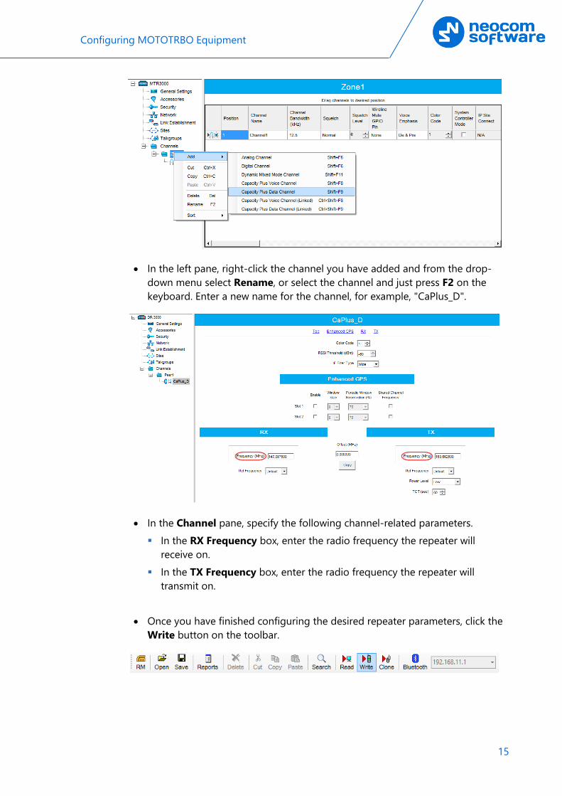
4.1.4.2 Adding a Data Channel • In the left pane, under Channels, right-click Zone and from the drop-down
menu, select Add > Capacity Plus Data Channel.
Configuring MOTOTRBO Equipment
15
• In the left pane, right-click the channel you have added and from the drop-down menu select Rename, or select the channel and just press F2 on the keyboard. Enter a new name for the channel, for example, "CaPlus_D".
• In the Channel pane, specify the following channel-related parameters. In the RX Frequency box, enter the radio frequency the repeater will
receive on. In the TX Frequency box, enter the radio frequency the repeater will
transmit on.
• Once you have finished configuring the desired repeater parameters, click the Write button on the toolbar.

16 TRBOnet Capacity Plus — Deployment Guide
4.2 Configuring a Control Station This section describes how to configure the radio to be used as a control station in a Capacity Plus system. Control stations are used in the topologies depicted in Figures 1-6.
• Connect your radio to the PC via a programming cable. • Turn on the radio. • Click the Read button on the toolbar.
4.2.1 General Settings • In the left pane, select General Settings. • In the General Settings pane, specify the following: Radio ID
Enter the Radio ID of the control station. The default value is 64250.
Note: This value will then be used as the control station’s Radio ID when connecting a control station to the TRBOnet Server. See section 5.1.2, Connecting a Control Station.

Configuring MOTOTRBO Equipment
17
4.2.2 Network • In the left pane, select Network.
• In the Network pane, specify the following parameters: Radio IP
This is the IP address used by the radio to communicate with the PC (using the USB connection) and has to be unique. To avoid conflicts in case there are several stations connected with USB, you can change the third octet of the address.
Accessory IP This is the IP address that is given to the PC by the radio that is connected to it.
Note: This value will then be used as the control station’s IP Address when connecting a control station to the TRBOnet Server. See section 5.1.2, Connecting a Control Station.
Forward to PC From the drop-down list, select Via USB.

18 TRBOnet Capacity Plus — Deployment Guide
4.2.3 Contacts • In the left pane, select Contacts > Capacity Plus and right-click it. Click Add >
and from the drop-down menu select the type of a call you want to add a contact for.
• Enter the Contact Name and Call ID for the contacts you have added.
4.2.4 RX Group Lists • In the left pane, select RX Group Lists > Capacity Plus. Right-click it, and
choose Add > RX Group List.
• In the left pane, select the group you have added. • In the right pane, in the Available list select a group, or multiple groups using
the SHIFT key, and click the Add button. As a result, the group(s) will appear in the Members list.

Configuring MOTOTRBO Equipment
19
4.2.5 Channel Depending on its role in a Capacity Plus system (Trunked Control Station or Data Revert Control Station), the radio can be configured either with a Capacity Plus Personality Channel or with a Digital Channel, respectively.
4.2.5.1 Adding a Capacity Plus Personality Channel • In the left pane, select Channels. Right-click it, and choose Add > Zone.
• In the left pane, select the zone you have added. Right-click it, and choose Add > Capacity Plus Personality.
• In the left pane, select the channel (for example, named CapPlus_TG10) that has previously been added.

20 TRBOnet Capacity Plus — Deployment Guide
• In the right pane, specify the following parameters: Privacy
Select this option to allow privacy on the channel.
Note: The Privacy option is available if the Basic or Enhanced Privacy Type has been selected in the Security section.
Privacy Alias From the drop-down list, select the Key Alias.
Note: The Privacy Alias option is available if the Enhanced Privacy Type has been selected in the Security section. The same Key Alias must be used on all system nodes (repeaters and radios).
Option Board Select this option to enable the option board capability on the channel. The option board must be installed and enabled in the radio otherwise this feature will not function.
Voice List Select the Capacity Plus Voice List you have specified in section 4.2.6, Capacity Plus Voice List.
RX Group List Select the Group list you have specified in section 4.2.4, RX Group Lists. If you select None, the radio will receive calls only from the group specified in the TX Contact Name box.

Configuring MOTOTRBO Equipment
21
TX Contact Name Select the contact to which a call will be initiated on the channel when pressing the PTT button. The contact is selected from the Contact list you have created in section 4.2.3, Contacts.
4.2.5.2 Adding Channels to Channel Pool Channel Pool is used for organizing channels in the radio that are not tied to a channel selector position. The Channel Pool is not visible when the radio user navigates through the zones.
• In the left pane, select Channels > Channel Pool. Right-click on it, and choose Add > Capacity Plus Voice Channel.
• In the left pane, select the first channel (for example, named CPlusMaster) that has previously been added.
Color Code Enter the color code for the radio. Note that the color codes on the radios must match the color code of the repeater.
Phone System Select the phone system you have specified in section 4.3.8, Phone System.
In the RX Frequency box, specify the radio frequency the radio will receive on.
In the TX Frequency box, specify the radio frequency the radio will transmit on.
Note: The RX and TX frequencies of the radio must be the opposite to the RX and TX frequencies of the repeater. In other words, the RX frequency of the repeater must be the same as the TX frequency of the radio; the TX frequency of the repeater must be the same as the RX frequency of the radio.

22 TRBOnet Capacity Plus — Deployment Guide
4.2.5.3 Adding a Digital Channel for Receiving Data • In the left pane, select the zone you have added. Right-click it, and choose
Add > Digital Channel. • In the left pane, select the channel (for example, named DataChannel1) that
has previously been added.
Color Code Enter the color code for the radio. Note that the color codes on the radios must match the color code of the data repeater.
Repeater/Time Slot Select one of the data repeater time slots.
Privacy Select this option to allow privacy on the channel.
Note: The Privacy option is available if the Basic or Enhanced Privacy Type has been selected in the Security section.
Privacy Alias From the drop-down list, select the Key Alias.
Note: The Privacy Alias option is available if the Enhanced Privacy Type has been selected in the Security section. The same Key Alias must be used on all system nodes (repeaters and radios).
Configuring MOTOTRBO Equipment
23
In the RX Frequency box, specify the radio frequency the radio will receive on.
In the TX Frequency box, specify the radio frequency the radio will transmit on.
Note: The RX and TX frequencies of the radio must be the opposite to the RX and TX frequencies of the corresponding data repeater. In other words, the RX frequency of the repeater must be the same as the TX frequency of the radio; the TX frequency of the repeater must be the same as the RX frequency of the radio.
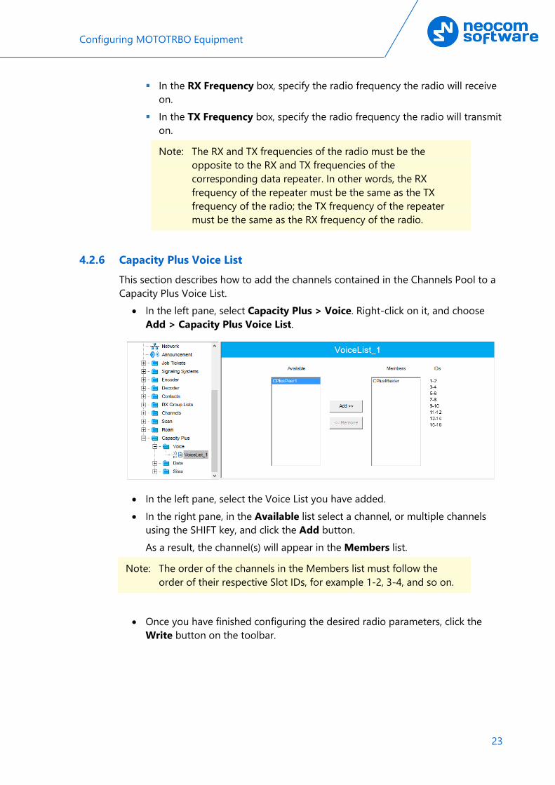
4.2.6 Capacity Plus Voice List This section describes how to add the channels contained in the Channels Pool to a Capacity Plus Voice List.
• In the left pane, select Capacity Plus > Voice. Right-click on it, and choose Add > Capacity Plus Voice List.
• In the left pane, select the Voice List you have added. • In the right pane, in the Available list select a channel, or multiple channels
using the SHIFT key, and click the Add button. As a result, the channel(s) will appear in the Members list.
Note: The order of the channels in the Members list must follow the order of their respective Slot IDs, for example 1-2, 3-4, and so on.
• Once you have finished configuring the desired radio parameters, click the
Write button on the toolbar.

24 TRBOnet Capacity Plus — Deployment Guide
4.3 Configuring a Subscriber Radio This section describes how to configure a subscriber radio to be used in a Capacity Plus system.
• Connect your radio to the PC via a programming cable. • Turn on the radio. • Click the Read button on the toolbar.
4.3.1 General Settings • In the left pane, select General Settings. • In the General Settings pane, specify the following: Radio ID
Enter the Radio ID of the radio. This ID is used by other calling radios when addressing the radio, for instance, when making a private call or sending a text message.
GPS Select this checkbox to track the location of the radio if the radio is equipped with a GPS module.
Private calls Select this checkbox to enable the initiation of a Private Call on a digital channel. When disabled, a prohibit tone will sound when the user tries to initiate a Private Call.
Configuring MOTOTRBO Equipment
25
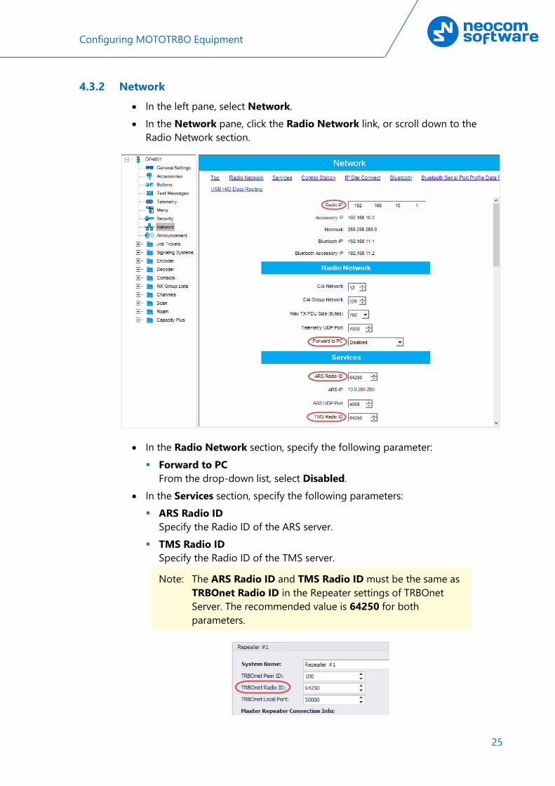
4.3.2 Network • In the left pane, select Network. • In the Network pane, click the Radio Network link, or scroll down to the
Radio Network section.
• In the Radio Network section, specify the following parameter: Forward to PC
From the drop-down list, select Disabled. • In the Services section, specify the following parameters: ARS Radio ID
Specify the Radio ID of the ARS server. TMS Radio ID
Specify the Radio ID of the TMS server.
Note: The ARS Radio ID and TMS Radio ID must be the same as TRBOnet Radio ID in the Repeater settings of TRBOnet Server. The recommended value is 64250 for both parameters.

26 TRBOnet Capacity Plus — Deployment Guide
4.3.3 Contacts • In the left pane, select Contacts > Capacity Plus and right-click on it. Click
Add > and from the drop-down menu select the type of a call you want to add a contact for.
• Enter the Contact Name and Call ID for the contacts you have added.
4.3.4 RX Group Lists • In the left pane, select RX Group Lists > Capacity Plus. Right-click on it, and
choose Add > RX Group List.
• In the left pane, select the group you have added. • In the right pane, in the Available list select a group, or multiple groups using
the SHIFT key, and click the Add button. As a result, the group(s) will appear in the Members list.

Configuring MOTOTRBO Equipment
27
4.3.5 Channels 4.3.5.1 Adding a Capacity Plus Personality Channel
• In the left pane, select Channels. Right-click on it, and choose Add > Zone.
• In the left pane, select the zone you have added. Right-click on it, and choose Add > Capacity Plus Personality.
• In the left pane, select the first channel (for example, named CapacityPlus) that has previously been added.

28 TRBOnet Capacity Plus — Deployment Guide
• In the right pane, specify the following parameters: ARS
Select On System Change to provide the automated registration for the radio.
Privacy Select this option to allow privacy on the channel.
Note: The Privacy option is available if the Basic or Enhanced Privacy Type has been selected in the Security section.
Privacy Alias From the drop-down list, select the Key Alias.
Note: The Privacy Alias option is available if the Enhanced Privacy Type has been selected in the Security section. The same Key Alias must be used on all system nodes (repeaters and radios).
Option Board Select this option to enable the option board capability on the channel. The option board must be installed and enabled in the radio or this feature will not function.
Voice List Select the Capacity Plus Voice List you have specified in section 4.3.6, Capacity Plus Voice List.
Data List Select the Capacity Plus Data List you have specified in section 4.3.7, Capacity Plus Data List.
Configuring MOTOTRBO Equipment
29
RX Group List Select the Group list you have specified in section 4.3.4, RX Group Lists.
TX Contact Name Select the contact to which a call will be initiated on the channel when pressing the PTT button. The contact is selected from the Contact list you have created in section 4.3.3, Contacts.
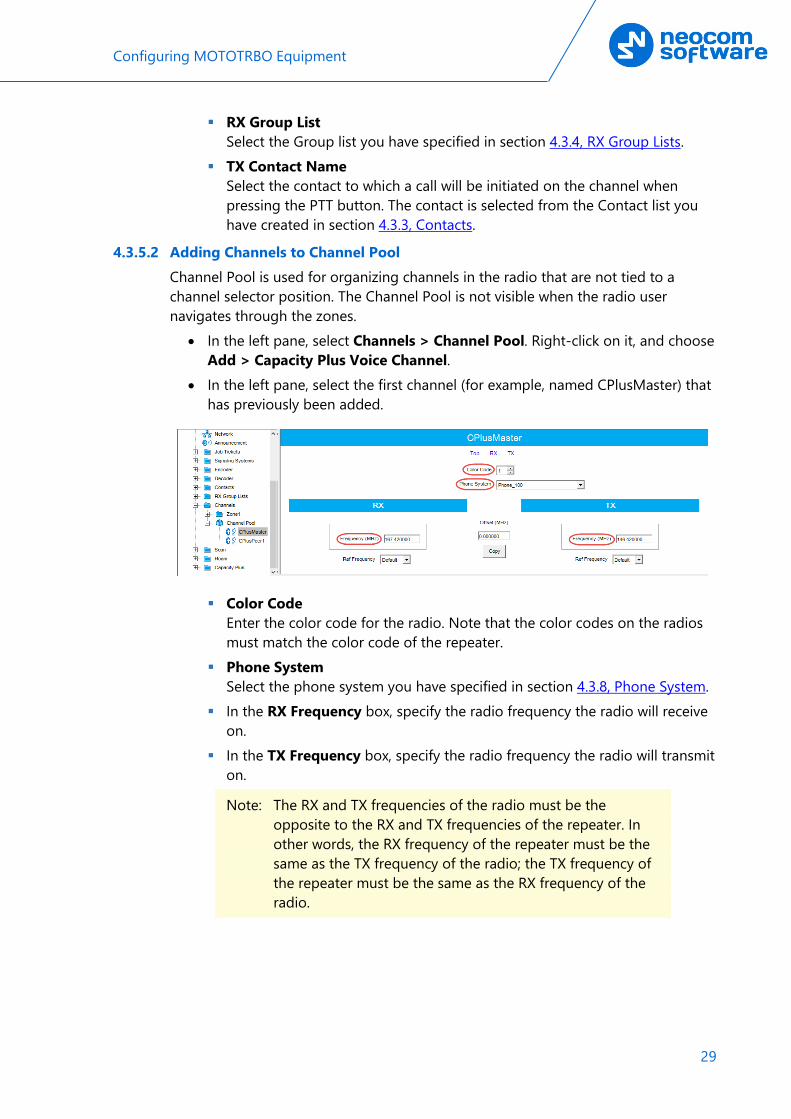
4.3.5.2 Adding Channels to Channel Pool Channel Pool is used for organizing channels in the radio that are not tied to a channel selector position. The Channel Pool is not visible when the radio user navigates through the zones.
• In the left pane, select Channels > Channel Pool. Right-click on it, and choose Add > Capacity Plus Voice Channel.
• In the left pane, select the first channel (for example, named CPlusMaster) that has previously been added.
Color Code Enter the color code for the radio. Note that the color codes on the radios must match the color code of the repeater.
Phone System Select the phone system you have specified in section 4.3.8, Phone System.
In the RX Frequency box, specify the radio frequency the radio will receive on.
In the TX Frequency box, specify the radio frequency the radio will transmit on.
Note: The RX and TX frequencies of the radio must be the opposite to the RX and TX frequencies of the repeater. In other words, the RX frequency of the repeater must be the same as the TX frequency of the radio; the TX frequency of the repeater must be the same as the RX frequency of the radio.

30 TRBOnet Capacity Plus — Deployment Guide
4.3.6 Capacity Plus Voice List This section describes how to add the channels contained in the Channels Pool to a Capacity Plus Voice List.
• In the left pane, select Capacity Plus > Voice. Right-click on it, and choose Add > Capacity Plus Voice List.
• In the left pane, select the Voice List you have added. • In the right pane, in the Available list select a channel, or multiple channels
using the SHIFT key, and click the Add button. As a result, the channel(s) will appear in the Members list.
Note: The order of the channels in the Members list must follow the order of their respective Slot IDs, for example 1-2, 3-4, and so on.
4.3.7 Capacity Plus Data List This section describes how to add the channels contained in the Channels Pool to a Capacity Plus Data List.
• In the left pane, select Capacity Plus > Data. Right-click on it, and choose Add > Capacity Plus Data List.
• In the left pane, select the Voice List you have added.

Configuring MOTOTRBO Equipment
31
• In the right pane, in the Available list select a channel, or multiple channels using the SHIFT key, and click the Add button. As a result, the channel(s) will appear in the Members list.
4.3.8 Phone System • In the left pane, select Signaling Systems > Phone. Right-click on it, and
choose Add > System. • In the left pane, under Phone, select the phone system that has been just
added.
• In the right pane, specify the following parameters: Gateway ID
Enter the same ID as TRBOnet Peer ID in the Repeater settings of TRBOnet Server.
TX Tone Duration (ms) Enter the duration of the DTMF tone digits, in milliseconds, for the phone system. It is recommended to set this value to 120.
TX Tone Interval (ms) Enter the duration of the intervals between the DTMF tone digits in a transmission sequence, in milliseconds, for the phone system. It is recommended to set this value to 80.
• Once you have finished configuring the desired radio parameters, click the Write button on the toolbar.

32 TRBOnet Capacity Plus — Deployment Guide
4.4 Configuring MOTOTRBO DDMS The DDMS, or Device Discovery and Mobility Service is a service for tracking the presence of radio subscribers in the radio network and transmitting the data to the server. The topologies using DDMS are depicted in Figures 6-7. This section describes how to configure and run MOTOTRBO DDMS service using MOTOTRBO DDMS Administrative Client.
• Launch MOTOTRBO DDMS Administrative Client. • In the left pane, select Watcher Settings.
PortWatcher This is the port number for listening TRBOnet Server requests.
Note: This value will be used when configuring DDMS parameters in section 5.1.1.3, DDMS Service, Service port.

Configuring MOTOTRBO Equipment
33
• In the left pane, select Authentication Server Settings.
AuthenticationServerIP This is the authentication server IP address.
AuthenticationServerPort This is the authentication server port number.
Note: These values will be used when configuring DDMS parameters in section 5.1.1.3, DDMS Service, Service IP Address and Authentication Port, respectively.
• Once you have finished configuring the desired DDMS parameters, click the Start button on the toolbar.

34 TRBOnet Capacity Plus — Deployment Guide
4.5 Configuring MOTOTRBO MNIS This section describes how to configure and run MOTOTRBO MNIS service using MNIS Configuration Utility.
• Launch MNIS Configuration Utility. • In the left pane, select General.
System Operation Mode From the drop-down list, select Capacity Plus.
MNIS Application ID Configure an individual ID that uniquely identifies the MNIS application in the radio system. Set this value to 64250.
MNIS IP Address It is recommended that the value of 172.168.10.1 is used unless there are conflicts with other network interfaces on the PC.
Tunnel IP Address This is the IP Address used by the MNIS to communicate with TRBOnet Enterprise (see 5.1.1.4, MNIS Data Service, IP Address).

Configuring MOTOTRBO Equipment
35
• In the left pane, select Capacity Plus
Master IP Address Enter the Ethernet IP address of the master repeater.
Master UDP Port Enter the UDP port number of the master repeater.
Authentication Key Enter the master repeater's authentication key (if any).

36 TRBOnet Capacity Plus — Deployment Guide
• In the left pane, select Advanced.
Compressed UDP Data Header From the drop-down list, select the type of compression protocol used for the UDP Data Header (None, MSI, DMR). It is recommended selecting MSI. Note that the same type must be set on all subscriber radio channels (CPS>Channels>Compressed UDP Data Header).
MNIS LE ID > Manually Assigned Enter a unique Peer ID among the repeaters in a radio system.

Configuring MOTOTRBO Equipment
37
• In the left pane, select Network
Device Discovery and Mobile Service
Server Address This is the IP address of the MOTOTRBO Device Discovery and Mobility Service (DDMS). The recommended value is 127.0.0.1 if both DDMS and MNIS reside on the same PC.
Watcher Port This is the port number on the MOTOTRBO Device Discovery and Mobility Service (DDMS) server to which the Watcher requests should be sent.
MNIS Control Interface
MNIS Control Interface TCP Port This is the Transmission Control Protocol (TCP) port for the MNIS Control Interface server. This value is used when connecting TRBOnet Server to MNIS Service (see 5.1.1.4, MNIS Data Service, Control port).

38 TRBOnet Capacity Plus — Deployment Guide
Once you have finished configuring the desired MNIS parameters, do the following: • Click the Save button on the toolbar.
• On the Configuration menu, click Set as Active Configuration.
• Click the Start button on the toolbar.

Configuring TRBOnet Enterprise
39
5 Configuring TRBOnet Enterprise This section describes how to configure TRBOnet Enterprise software. By properly configuring TRBOnet Server and TRBOnet Dispatch Console, you will be able to utilize the full capabilities of your Capacity Plus system.
5.1 Configuring TRBOnet Server To start TRBOnet Server, click the corresponding shortcut on the desktop, or click Start > All Programs > Neocom Software > TRBOnet Server x.x For how to configure TRBOnet Server’s Database, Service, Network parameters, etc., refer to TRBOnet Enterprise Quick Start Guide.
5.1.1 Connecting a Master Repeater This section describes how to configure TRBOnet Server for communication with the master repeater of a Capacity Plus system.
Note: Only the Master repeater needs to be connected to TRBOnet Server.
• In the Digital Systems pane, click Add. Or, in the Configuration pane, right-click Digital Systems.
• In the drop-down menu, click Add MOTOTRBO System.
In the Repeater pane, specify the connection parameters. To ensure your connection parameters match the actual configuration of your radio network, you may need to use Motorola CPS to determine the values. Contact your radio network administrator, if you do not have this information.

40 TRBOnet Capacity Plus — Deployment Guide
• System Name Enter a name for the repeater. This name will be displayed in the Dispatch Console.
• TRBOnet Peer ID Enter a Peer ID for TRBOnet Server. The Peer ID must be unique among the repeaters in the radio system. Consult your radio network administrator to enter the correct value.
• TRBOnet Radio ID Enter the Radio ID, which is a gateway for voice and data. The Radio ID must be unique in the radio system. Consult your radio network administrator to enter the correct value. The recommended value is 64250.
• TRBOnet Local Port Enter the local port number that will be used by TRBOnet Server to establish a connection to the repeater. Use unique port numbers for each repeater connection if there are several repeaters connected.
• Master IP Address Enter the Ethernet IP address of the master repeater.
Note: This value is programmed for a repeater via MOTOTRBO CPS, in Link Establishment>Master IP. See section 4.1.3.
• Master UDP Port Enter the UDP port number of the master repeater.
Note: This value is programmed for a repeater via MOTOTRBO CPS, in Link Establishment>Master UDP Port. See section 4.1.3.
• Authentication Key Enter the repeater's authentication key (if any).

Configuring TRBOnet Enterprise
41
Note: This value is programmed for a repeater via MOTOTRBO CPS, in Link Establishment>Authentication Key. See section 4.1.3.
• System Type From the drop-down list, select Capacity Plus.
• Test Click this button to check the connection to your master repeater. If the test is successful, you'll see the information on the repeater you are connected to, such as the serial number, firmware version, and other relevant information.
• System Identifier Enter the system identifier. Note that the system identifier should be the same for all control stations and repeaters used in the same radio system.
• Use NAI Voice, Use NAI Data (MNIS and DDMS) Select these options if the Network Application Interface Voice and Network Application Interface Data features are enabled on the repeaters.
Click Apply after entering all the required values. A confirmation dialog will appear, prompting you to save the configuration and restart the TRBOnet Server service. You can also restart the service manually.
5.1.1.1 Advanced Settings • In the Configuration pane, under the corresponding Repeater, select
Advanced settings.
Note: These settings are applicable only when Use NAI Voice and Use NAI Data (MNIS and DDMS) are deselected in the Repeater pane.

42 TRBOnet Capacity Plus — Deployment Guide
• In the Advanced Settings pane, specify the following repeater-related advanced settings: Voice Call Hang Time (ms): Group Call
This value sets the duration the repeater reserves the channel after the end of a group call transmission. During this time, only members of the group that the channel is reserved for can transmit.
Private Call This value sets the duration a radio keeps the private call setup after a user releases the PTT button. This is to avoid setting up the call again each time a user presses the PTT button to transmit. During this time, other radios can still transmit since the channel is essentially idle. After the hang timer expires, the radio transmits using the TX Contact Name parameter specified for this channel in MOTOTRBO CPS.
Emergency Call This value sets the duration the repeater reserves the channel after the end of an emergency call transmission. During this time, only members of the Group that the channel is reserved for can transmit.
Note: The values of the above three parameters must be taken from the corresponding parameter values programmed for the repeater via MOTOTRBO CPS in General Settings.
TX Preamble Enter the value of the TX Preamble. The TX Preamble is a string of bits added in front of a data or control message (Text Messaging, Location Messaging, Registration, Radio Check, Private Call, and other message types) before transmission. The acceptable range is 0 - 8640 ms. The recommended value is 120 ms.
TX Timeout Enter the time, in seconds, to be used as a voice session limit. When the dispatcher starts any voice session in the Dispatch Console, transmission will be interrupted after this TX Timeout expires.
Phone system From the drop-down list, select the system for phone calls: • Motorola Phone System
This system uses a special call type with the parameters specified for a radio unit in MOTOTRBO CPS. The Motorola Phone System is recommended for IP Site Connect mode to minimize Radio response time.
• TRBOnet Phone System (TX Interrupt) This is a phone call system based on the private call type using TX Interrupt feature. This phone system is available for radio systems with control stations.

Configuring TRBOnet Enterprise
43
5.1.1.2 Privacy • In the Configuration pane, under the corresponding Repeater, select Privacy.
• In the Privacy pane, specify the following privacy-related settings: Privacy Type
From the drop-down list, select one of the privacy types: None, Basic, or Enhanced.
Basic Privacy Key ID Enter the Privacy Key ID available for the Basic privacy type.
Enhanced Algorithm From the drop-down list, select one of the enhanced algorithms if you are going to use additional encryption.
Enhanced Privacy Keys Here you add enhanced privacy keys for the selected enhanced algorithm. • Click Add and specify the required ID, name, and value for the privacy
key being added.
5.1.1.3 DDMS Service The DDMS, or Device Discovery and Mobility Service is a service for tracking the presence of radio subscribers in the radio network and transmitting the data to the server.
• In the Configuration pane, under the corresponding Repeater, select DDMS service.

44 TRBOnet Capacity Plus — Deployment Guide
• In the DDMS service pane, specify the following DDMS service-related settings: Use DDMS service
Select this option to enable the DDMS service for the server. Local Port
Enter the number of the local port to be used on a PC with TRBOnet Dispatch Software for DDMS service.
Service IP Address Enter the IP Address of the PC with the DDMS service installed and running.
Service port Enter the service port number.
Note: This value is programmed for a DDMS service via MOTOTRBO DDMS Administrative Client, in Interfaces>Watcher Settings>PortWatcher.
Authentication Port Enter the authentication server port number.
Note: This value is programmed for a DDMS service via MOTOTRBO DDMS Administrative Client, in Interfaces>Authentication Server Settings> AuthenticationServerPort.
Radio ID list Enter the list of radios to be monitored.
Redundant services Here you see the list of redundant DDMS services for failover purposes.

Configuring TRBOnet Enterprise
45
• Click Add and specify the required parameters for the DDMS service being added.
• Click Test to test if the selected DDMS service is available. • Use the Up ( ) and Down ( ) buttons to move a selected DDMS
service up and down in the priority list of DDMS services.
5.1.1.4 MNIS Data Service The MNIS, or Motorola Network Interface Service, is a Windows application which acts as a data gateway between the data applications and the radio system. Data messages are routed through the MNIS.
• In the Configuration pane, under the corresponding Repeater, select MNIS data service.
• In the MNIS data service pane, specify the following MNIS data service-related settings: Use Data Gateway
Select this option to enable the MNIS data service for the server. Service is on a local host
Select this option if the MNIS data service will be used on the local PC. IP Address
Enter the IP Address used by the MNIS to communicate with the PC.
Note: This value is programmed for a MNIS data service via MOTOTRBO MNIS Configuration Utility, and can be retrieved from General>Tunnel Network>Tunnel IP Address.
Control port Enter the number for the MNIS control port.

46 TRBOnet Capacity Plus — Deployment Guide
Note: This value is programmed for a MNIS data service via MOTOTRBO MNIS Configuration Utility, in Advanced>Network>MNIS Control Interface TCP Port.
MNIS Service Select this option, and from the drop-down list select the available MNIS service.
Redundant services Here you see the list of redundant MNIS data services for failover purposes. • Click Add and specify the required parameters for the MNIS data service
being added. • Click Test to test if the selected MNIS data service is available. • Use the Up ( ) and Down ( ) buttons to move a selected MNIS data
service up and down in the priority list of MNIS data services.
5.1.1.5 Audio Paths The Audio Paths are talk paths of the system to make and receive Voice Calls; in general, they are talk groups. TRBOnet Server requires that all audio paths of a Capacity Plus system be registered in its configuration. If an audio path is not registered, the TRBOnet operator will not be able to receive and transmit to the corresponding talk group.
• In the Configuration pane, under the corresponding Repeater, select Audio Paths.
• In the Audio Paths pane, specify the following Audio Path-related settings: To add an audio path to the system, click Add.
Configuring TRBOnet Enterprise
47
Make sure the check box in the first column is selected to make and receive voice calls from the selected subscriber.
From the drop-down list, select the Call Type for the audio path. The available call types are All Call, Group Call, and Private Call.
Enter the Group ID, which is an ID of the talk group the dispatcher can make calls to. The Group ID is not applicable for Private Calls and All Calls.
To configure the selected audio path, click Configure. Specify the desired audio path settings similar to those for a common
repeater slot.
5.1.2 Connecting a Control Station This section describes how to configure TRBOnet Server for communication with a control station in a Capacity Plus system.
• In the Digital Systems pane, click Add. Or, in the Configuration pane, right-click Digital Systems.
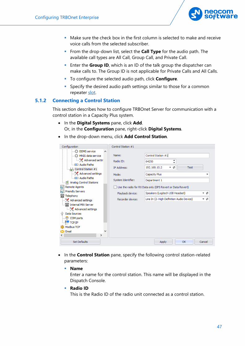
• In the drop-down menu, click Add Control Station.
• In the Control Station pane, specify the following control station-related parameters: Name
Enter a name for the control station. This name will be displayed in the Dispatch Console.
Radio ID This is the Radio ID of the radio unit connected as a control station.
48 TRBOnet Capacity Plus — Deployment Guide
Note: This box is populated automatically once you have successfully tested the control station by clicking the Test button.
IP Address Enter, or select from the list, the IP Address of the control station network interface.
Note: This value can be taken from the radio's configuration in MOTOTRBO CPS, in Network>Accessory IP.
Test Click this button to check the connection to the control station. If the test is successful, you'll see the information on the control station you are connected to, such as radio ID, serial number, firmware version, and other relevant information.
Mode From the drop-down list, select Capacity Plus.
System Identifier Enter the system identifier. Note that the system identifier should be the same for all control stations and repeaters used in the same radio system.
Use the radio for RX data only (GPS Revert or Data Revert) Select this option to configure the radio channel so that it will only receive data, thus having no transmission capability.
Playback device From the drop-down list, select the playback device on the PC that will be used to transfer audio data to the connected control station.
Recorder device From the drop-down list, select the recording device on the PC that will be used to receive audio data from the control station connected via a line-in jack.
• Click Apply after entering all the required values. A confirmation dialog will appear, prompting you to save the configuration and restart the TRBOnet Server service. You can also restart the service manually.

Configuring TRBOnet Enterprise
49
5.1.2.1 Advanced Settings • In the Configuration pane, under the corresponding Control Station, select
Advanced Settings.
• In the Advanced Settings pane, specify the following control station-related advanced settings: Automatically reset alarm mode
Select this option to reset alarm mode on the control station radio automatically. It is recommended to enable this option.
Automatically handle call alert Select this option to automatically redirect call alerts from the control station radio to the Dispatch Console.
Emergency Call/Alarm indication Select this option so that audio and visual indication is given by the control station radio when an emergency Call/Emergency Alarm is received.
Use front microphone (for PTT key up) Select this option to use a remote control of the PTT button via a remote speaker microphone on the radio.
Always transmit when the PTT is pressed ("Impolite" channel access) Select this option so that when the PTT button is pressed, the radio will start transmitting regardless of whether the channel is free or not (that is any transmission in progress will be interrupted).
Use serial port for PTT key up Select this option to use a remote control of the PTT button via the serial port of the PC, and select the serial port from the drop-down list.

50 TRBOnet Capacity Plus — Deployment Guide
TX Timeout Enter the time, in seconds, to be used as a voice session limit. When a dispatcher starts any voice session in the Dispatch Console, the ongoing transmission will be interrupted after this TX Timeout expires.
Signaling system From the drop-down list, select the signaling system. • MDC 1200 signaling is a Motorola data system using audio frequency
shift keying (ASFK) using a 1,200 baud data rate. A general option is to enable or disable an acknowledgement (ACK) data packet.
• SELECT 5 (5 Tone Signaling System). In the 5 Tone Signaling Systems, each radio has a unique numeric identity (for example, 12345).
Allow CSBK Data Select this option so that the GPS data are compressed into a single CSBK data.
5.1.2.2 Audio Paths The Audio Paths are talk paths of the system to make and receive Voice Calls; in general, they are talk groups. TRBOnet Server requires that all audio paths of a radio system be registered in its configuration. If an audio path is not registered, the TRBOnet operator will not be able to receive and transmit to the corresponding talk group.
• In the Configuration pane, under the corresponding Control Station, select Audio Paths.
• In the Audio Paths pane, specify the following Audio Path-related settings: To add an audio path to the system, click Add.

Configuring TRBOnet Enterprise
51
Make sure the check box in the first column is selected to make and receive voice calls from the selected subscriber.
From the drop-down list, select the Call Type for the audio path. The available call types are All Call, Group Call, and Private Call.
Enter the Group ID, which is an ID of the talk group the dispatcher can make calls to. The Group ID is not applicable for Private Calls and All Calls.
5.1.3 Enabling Telephony TRBOnet Server has its own built-in SIP server to support VoIP communications between the radios as well as other SIP-compliant clients.
• In the Configuration pane, select Telephony • In the Telephony pane, select Use Telephony.

52 TRBOnet Capacity Plus — Deployment Guide
5.1.3.1 Internal PBX Server • Make sure the Internal PBX Server option is selected in the Telephony pane. • In the Configuration pane, select Internal PBX Server.
• In the Internal PBX Server pane, specify the following parameters: Local IP
Enter the IP address of the PC with TRBOnet Server. Port
Enter the local UDP port number for the SIP service (5060, by default).
Dispatch Center
SIP ID Enter the SIP ID that will be used by the Dispatch Center.
SIP user Enter the SIP user name that will be used by the Dispatch Center.

Configuring TRBOnet Enterprise
53
5.2 Configuring TRBOnet Dispatch Console To start TRBOnet Server, click the corresponding shortcut on the desktop, or click Start > All Programs > Neocom Software > TRBOnet Dispatch x.x The dialog box will appear prompting you to enter the TRBOnet Server IP address, User Name, and Password. The default Administrator credentials are admin for the login and admin for the password. For a more detailed information on how to use TRBOnet Dispatch Console, refer to TRBOnet Enterprise User Manual.
5.2.1 Registering Radio Groups Go to Administration (1), Radio Group (2) to add/edit/delete Radio Groups in the system.
• Click Add (3) to add a radio group to the system: • In the dialog box that appears, specify the Name and Group ID (Radio ID) of
the group you are adding.
Note: Make sure that the radio group(s) created in the Dispatch Console are present in the radio’s RX Group List (see section 4.3.4, RX Group Lists). In addition, make sure these radio groups have been added to TRBOnet Server as Audio Paths.

54 TRBOnet Capacity Plus — Deployment Guide
5.2.2 Registering Radios Go to Administration (1), Radios (2) to add/edit/delete Radios in the system.
• Click Add MOTOTRBO Radio (3) to add a new radio. • In the dialog box that appears, specify the Callsign and Radio ID, and Radio
Groups, to which the radio belongs.

Configuring TRBOnet Enterprise
55
5.2.3 Registering SIP extensions This section describes how to add SIP extensions to TRBOnet Dispatch Console.
• Go to Administration (1), Telephony (2). • In the Telephone pane, click the Extensions tab (3), and then Add > SIP
Phone (4).
• In the dialog box that appears, specify the SIP ID and SIP User of the SIP user you are adding.