tre1706008802-azumi s.a-fcc part 15.247-wifi bgn(h40) · shenzhen huatongwei international...
TRANSCRIPT
The test report merely corresponds to the test sample. It is not permitted to copy extracts of these test result without the written permission of the test laboratory.
TEST REPORT
Report Reference No. .................... : TRE1706008802 R/C…….: 56915
FCC ID ............................................. : QRP-AZUMIKIREIA5D
Applicant’s name ........................... : Azumi S.A
Address ............................................. : Avenida Aquilino de la Guardia con Calle 47, PH Ocean Plaza, Piso 16 of. 16-01, Marbella, Ciudad de Panama, Panama
Manufacturer......................................: AZUMI HK LTD
Address...............................................: FLAT/RM 18 BLK 1 14/F GOLDEN INDUSTRIAL BUILDING 16-26 KWAI TAK STREET KWAI CHUNG,HK
Test item description .................... : 3G Mobile Phone
Trade Mark ....................................... : -
Model/Type reference ....................... : KIREI A5 D
Listed Model(s) ................................. : -
Standard ......................................... : FCC CFR Title 47 Part 15 Subpart C Section 15.247
Date of receipt of test sample………..: Jun. 12, 2017
Date of testing…………………………: Jun. 13, 2017 - Jun. 22, 2017
Date of issue…………………………...: Jun. 23, 2017
Result .................. …………………...: PASS
Compiled by
( position+printedname+signature) ... : File administrators Candy Liu
Supervised by
(position+printedname+signature) .... : Project Engineer Lion Cai
Approved by
(position+printedname+signature) .... :
RF Manager Hans Hu
Testing Laboratory Name ............. : Shenzhen Huatongwei International Inspection Co., Ltd.
Address ............................................. : 1/F, Bldg 3, Hongfa Hi-tech Industrial Park, Genyu Road, Tianliao, Gongming, Shenzhen, China
Shenzhen Huatongwei International Inspection Co., Ltd. All rights reserved.
This publication may be reproduced in whole or in part for non-commercial purposes as long as the Shenzhen Huatongwei International Inspection Co., Ltd. is acknowledged as copyright owner and source of the material. Shenzhen Huatongwei International Inspection Co., Ltd. takes no responsibility for and will not assume liability for damages resulting from the reader's interpretation of the reproduced material due to its placement and context.
Report No.: TRE1706008802 Page 2 of 40 Issued: 2017-06-23
Report Template Version: H00 (2016-08)
Contents
1. TEST STANDARDS AND REPORT VERSION 3
1.1. Applicable Standards 3 1.2. Report version 3
2. TEST DESCRIPTION 4
3. SUMMARY 5
3.1. Client Information 5 3.2. Product Description 5 3.3. Operation state 6 3.4. EUT configuration 6 3.5. Modifications 6
4. TEST ENVIRONMENT 7
4.1. Address of the test laboratory 7 4.2. Test Facility 7 4.3. Equipments Used during the Test 8 4.4. Environmental conditions 9 4.5. Statement of the measurement uncertainty 9
5. TEST CONDITIONS AND RESULTS 1 0
5.1. Antenna requirement 10 5.2. Conducted Emission (AC Main) 11 5.3. Conducted Peak Output Power 14 5.4. Power Spectral Density 15 5.5. 6dB bandwidthand 19 5.6. Restricted band 23 5.7. Band edge and Spurious Emission (conducted) 27 5.8. Spurious Emission (radiated) 32
6. TEST SETUP PHOTOS OF THE EUT 3 9
7. EXTERNAL AND INTERNAL PHOTOS OF THE EUT 4 0

Report No.: TRE1706008802 Page 3 of 40 Issued: 2017-06-23
Report Template Version: H00 (2016-08)
1. Test standards and Report version 1.1. Applicable Standards The tests were performed according to following standards: FCC Rules Part 15.247: Frequency Hopping, Direct Spread Spectrum and Hybrid Systems that are in operation within the bands of 902-928 MHz, 2400-2483.5 MHz, and 5725-5850 MHz. ANSI C63.10:2013: American National Standard forTesting Unlicensed Wireless Devices KDB 558074 D01 DTS Meas Guidance v03r05: Guidance for Performing Compliance Measurements on Digital Transmission Systems (DTS) Operating under §15.247
1.2. Report version
Version No. Date of issue Description
00 Jun.23, 2017 Original

Report No.: TRE1706008802 Page 4 of 40 Issued: 2017-06-23
Report Template Version: H00 (2016-08)
2. Test Description
Test Item Section in CFR 47 Result
Antenna requirement 15.203/15.247 (c) Pass
Line Conducted Emission (AC Main) 15.207 Pass
Conducted Peak Output Power 15.247 (b)(3) Pass
Power Spectral Density 15.247 (e) Pass
6dB Bandwidth 15.247 (a)(2) Pass
Restricted band 15.247(d)/15.205 Pass
Spurious Emission 15.247(d)/15.209 Pass
Note: The measurement uncertainty is not included in the test result.
Report No.: TRE1706008802 Page 5 of 40 Issued: 2017-06-23
Report Template Version: H00 (2016-08)
3. Summary 3.1. Client Information
Applicant: Azumi S.A
Address: Avenida Aquilino de la Guardia con Calle 47, PH Ocean Plaza, Piso 16 of. 16-01, Marbella, Ciudad de Panama, Panama
Manufacturer: AZUMI HK LTD
Address: FLAT/RM 18 BLK 1 14/F GOLDEN INDUSTRIAL BUILDING 16-26 KWAI TAK STREET KWAI CHUNG,HK
3.2. Product Description
Name of EUT: 3G Mobile Phone
Trade Mark: -
Model No.: KIREI A5 D
Listed Model(s): -
Power supply: DC 3.8V From internal battery
Adapter information: Input: 100-240Va.c., 50/60Hz, 0.2A Output: 5Vd.c., 1A
WIFI
Supported type: 802.11b 802.11g 802.11n(H20) 802.11n(H40)
Modulation: DSSS for 802.11b
OFDM for 802.11g/802.11n(H20)/802.11n(H40)
Operation frequency: 2412MHz~2462MHz for 802.11b/802.11g/802.11n(H20)
2422MHz~2452MHz for 802.11n(H40)
Channel number: 11 for 802.11b/802.11g/802.11n(H20)
7 for 802.11n(H40)
Channel separation: 5MHz
Antenna type: Integral antenna
Antenna gain: 1.6 dBi

Report No.: TRE1706008802 Page 6 of 40 Issued: 2017-06-23
Report Template Version: H00 (2016-08)
3.3. Operation state
Test frequency list
According to section 15.31(m), regards to the operating frequency range over 10 MHz, must select three channel which were tested. the Lowest frequency, the middle frequency, and the highest frequency of channel were selected to perform the test, please see the above gray bottom.
802.11b/g/n(H20) 802.11n(H40)
Channel Frequency (MHz) Channel Frequency (MHz)
01 2412 01 -
02 2417 02 -
03 2422 03 2422
04 2427 04 2427
05 2432 05 2432
06 2437 06 2437
07 2442 07 2442
08 2447 08 2447
09 2452 09 2452
10 2457 10 -
11 2462 11 -
Test mode
For RF test items
The engineering test program was provided and enabled to make EUT continuous transmit(duty cycle>98%).
For AC power line conducted emissions:
The EUT was set to connect with the WLAN AP under large package sizes transmission.
For RF test axis
EUT in each of three orthogonal axis emissions had been tested ,but only the worst case (X axis) dataRecorded in the report.
3.4. EUT configuration The following peripheral devices and interface cables were connected during the measurement: ● - supplied by the manufacturer ○ - supplied by the lab
Length (m) : /
Shield : /
Detachable : /
Manufacturer : /
Model No. : /
3.5. Modifications No modifications were implemented to meet testing criteria.

Report No.: TRE1706008802 Page 7 of 40 Issued: 2017-06-23
Report Template Version: H00 (2016-08)
4. Test Environment 4.1. Address of the test laboratory Laboratory:Shenzhen Huatongwei International Inspection Co., Ltd. Address: 1/F, Bldg 3, Hongfa Hi-tech Industrial Park, Genyu Road, Tianliao, Gongming, Shenzhen, China Phone: 86-755-26748019 Fax: 86-755-26748089
4.2. Test Facility The test facility is recognized, certified, or accredited by the following organizations: CNAS-Lab Code: L1225 Shenzhen Huatongwei International Inspection Co., Ltd. has been assessed and proved to be in compliance with CNAS-CL01 Accreditation Criteria for Testing and Calibration Laboratories (identical to ISO/IEC17025: 2005 General Requirements) for the Competence of Testing and Calibration Laboratories, Date of Registratio-n: February 28, 2015. Valid time is until February 27, 2018. A2LA-Lab Cert. No. 3902.01 Shenzhen Huatongwei International Inspection Co., Ltd. EMC Laboratory has been accredited by A2LA for technical competence in the field of electrical testing, and proved to be in compliance with ISO/IEC 17025: 2005 General Requirements for the Competence of Testing and Calibration Laboratories and any additional program requirements in the identified field of testing. Valid time is until March 31, 2017. FCC-Registration No.: 317478 Shenzhen Huatongwei International Inspection Co., Ltd. EMC Laboratory has been registered and fully described in a report filed with the FCC (Federal Communications Commission). The acceptance letter from the FCC is maintained in our files. Registration 317478, Renewal date Jul. 18, 2014, valid time is until Jul. 18, 2017. IC-Registration No.: 5377B Two 3m Alternate Test Site of Shenzhen Huatongwei International Inspection Co., Ltd. has been registered byCertification and Engineering Bureau of Industry Canada for the performance of radiated measurements with Registration No. 5377B on Dec.03, 2014, valid time is until Dec. 03, 2017. ACA Shenzhen Huatongwei International Inspection Co., Ltd. EMC Laboratory can also perform testing for the Australian C-Tick mark as a result of our A2LA accreditation.

Report No.: TRE1706008802 Page 8 of 40 Issued: 2017-06-23
Report Template Version: H00 (2016-08)
4.3. Equipments Used during the Test
Conducted Emission (AC Main) Item Test Equipment Manufacturer Model No. Serial No. Last Cal 1 Artificial Mains Rohde&Schwarz ESH2-Z5 100028 2016/11/13 2 EMI Test Receiver Rohde&Schwarz ESCI3 100038 2016/11/13 3 Pulse Limiter Rohde&Schwarz ESHSZ2 100044 2016/11/13 4 EMI Test Software Rohde&Schwarz ES-K1 V1.71 N/A N/A
Radiated Emission Item Test Equipment Manufacturer Model No. Serial No. Last Cal
1 Ultra-Broadband Antenna
ShwarzBeck VULB9163 538 2016/11/13
2 EMI TEST RECEIVER Rohde&Schwarz ESI 26 100009 2016/11/13 3 EMI TEST Software Audix E3 N/A N/A 4 TURNTABLE ETS 2088 2149 N/A 5 ANTENNA MAST ETS 2075 2346 N/A 6 EMI TEST Software Rohde&Schwarz ESK1 N/A N/A 7 HORNANTENNA ShwarzBeck 9120D 1011 2016/11/13 8 Amplifer Sonoma 310N E009-13 2016/11/13
9 JS amplifer Rohde&Schwarz JS4-00101800-28-5A
F201504 2016/11/13
10 High pass filter Compliance Direction systems
BSU-6 34202 2016/11/13
11 HORNANTENNA ShwarzBeck 9120D 1012 2016/11/13
12 Amplifer Compliance Direction systems
PAP1-4060 120 2016/11/13
13 Loop Antenna Rohde&Schwarz HFH2-Z2 100020 2016/11/13 14 TURNTABLE MATURO TT2.0 ---- N/A 15 ANTENNA MAST MATURO TAM-4.0-P ---- N/A 16 Horn Antenna SCHWARZBECK BBHA9170 25841 2016/11/13
17 ULTRA-BROADBAND ANTENNA
Rohde&Schwarz HL562 100015 2016/11/13
Maximum Peak Output Power / Power Spectral Density / 6dB Bandwidth / Band Edge Compliance of RF Emission / Spurious RF Conducted Emission Item Test Equipment Manufacturer Model No. Serial No. Last Cal 1 Spectrum Analyzer Rohde&Schwarz FSP 1164.4391.40 2016/11/13 2 Power Meter Anritsu ML2480B 100798 2016/11/13 3 Power Sensor Anritsu MA2411B 100258 2016/11/13
The Cal.Interval was one year

Report No.: TRE1706008802 Page 9 of 40 Issued: 2017-06-23
Report Template Version: H00 (2016-08)
4.4. Environmental conditions During the measurement the environmental conditions were within the listed ranges:
Temperature: 15~35°C
lative Humidity: 30~60 %
Air Pressure: 950~1050mba
4.5. Statement of the measurement uncertainty The data and results referenced in this document are true and accurate. The reader is cautioned that there may be errors within the calibration limits of the equipment and facilities. The measurement uncertainty was calculated for all measurements listed in this test report acc. to TR-100028-01”Electromagnetic compatibilityand Radio spectrum Matters (ERM);Uncertainties in the measurementof mobile radio equipment characteristics;Part 1”and TR-100028-02 “Electromagnetic compatibilityand Radio spectrum Matters (ERM);Uncertainties in the measurementof mobile radio equipment characteristics;Part 2 “ and is documented in the Shenzhen Huatongwei International Inspection Co., Ltd quality system acc. to DIN EN ISO/IEC 17025. Furthermore, component and process variability of devices similar to that tested may result in additional deviation. The manufacturer has the sole responsibility of continued compliance of the device. Hereafter the best measurement capability for Shenzhen Huatongwei laboratory is reported:
Test Items MeasurementUncertainty Notes
Transmitter power conducted 0.57 dB (1) Transmitter power Radiated 2.20 dB (1) Conducted spurious emission 9 kHz-40 GHz 1.60 dB (1) Radiated spurious emission 9 kHz -40 GHz 2.20 dB (1) Conducted Emission 9 kHz -30 MHz 3.39 dB (1) Radiated Emission 30~1000 MHz 4.24 dB (1) Radiated Emissio 1~18 GHz 5.16 dB (1) Radiated Emissio 18-40 GHz 5.54 dB (1) Occupied Bandwidth --------- (1) (1) This uncertainty represents an expanded uncertainty expressed at approximately the 95% confidence
level using a coverage factor of k=1.96.

Report No.: TRE1706008802 Page 10 of 40 Issued: 2017-06-23
Report Template Version: H00 (2016-08)
5. Test Conditions and Results 5.1. Antenna requirement REQUIREMENT: FCC CFR Title 47 Part 15 Subpart C Section 15.203: An intentional radiator shall be designed to ensure that no antenna other than that furnished by the responsible party shall be used with the device. The use of a permanently attached antenna or of anantenna that uses a unique coupling to the intentional radiator, the manufacturer may design the unit so that a broken antenna can be replaced by the user, but the use of a standard antenna jack or electrical connector is prohibited.
FCC CFR Title 47 Part 15 Subpart C Section 15.247(c) (1)(i):
(i) Systems operating in the 2400-2483.5 MHz band that is used exclusively for fixed. Point-to-point operations may employ transmitting antennas with directional gain greater than 6dBi provided the maximum conducted output power of the intentional radiator is reduced by 1 dB for every 3 dB that the directional gain of the antenna exceeds 6dBi.
TEST RESULTS
Passed Not Applicable
The antenna is integral antenna, the best case gain of the antenna is 1.6dBi, please refer to the below antenna photo.
WIFI/BT ANT GSM/WCDMA ANT

Report No.: TRE1706008802 Page 11 of 40 Issued: 2017-06-23
Report Template Version: H00 (2016-08)
5.2. Conducted Emission (AC Main)
LIMIT
FCC CFR Title 47 Part 15 Subpart C Section 15.207:
Frequency range (MHz) Limit (dBuV)
Quasi-peak Average 0.15-0.5 66 to 56* 56 to 46*
0.5-5 56 46 5-30 60 50
* Decreases with the logarithm of the frequency.
TEST CONFIGURATION
TEST PROCEDURE
1. The EUT was setup according to ANSI C63.10:2013 for compliance to FCC 47CFR 15.247 requirements.
2. The EUT was placed on a platform of nominal size, 1 m by 1.5 m, raised 80 cm above theconducting ground plane. The vertical conducting plane was located 40 cm to the rear of theEUT. All other surfaces of EUT were at least 80 cm from any other grounded conductingsurface.
3. The EUT and simulators are connected to the main power through a line impedance stabilization network (LISN). The LISN provides a 50 ohm /50uH coupling impedance for themeasuring equipment.
4. The peripheral devices are also connected to the main power through aLISN. (Please refer to the block diagram of the test setup and photographs)
5. Each current-carrying conductor of the EUT power cord, except the ground (safety) conductor,was individually connected through a LISN to the input power source.
6. The excess length of the power cord between the EUT and the LISN receptacle were foldedback and forth at the center of the lead to form a bundle not exceeding 40 cm in length.
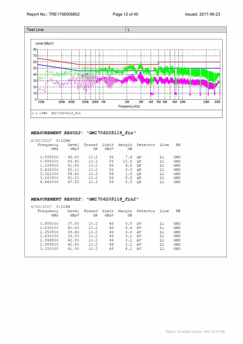
7. Conducted emissions were investigated over the frequency range from 0.15MHz to 30MHz using a receiver bandwidth of 9 kHz.
8. During the above scans, the emissions were maximized by cable manipulation. TEST MODE: Please refer to the clause 3.3 TEST RESULTS
Passed Not Applicable Note: 1) Transd=Cable lose+ Pulse Limiter Factor + Artificial Mains Factor 2) Margin= Limit -Level
Report No.: TRE1706008802 Page 12 of 40 Issued: 2017-06-23
Report Template Version: H00 (2016-08)
Test Line: L

Report No.: TRE1706008802 Page 13 of 40 Issued: 2017-06-23
Report Template Version: H00 (2016-08)
Test Line: N

Report No.: TRE1706008802 Page 14 of 40 Issued: 2017-06-23
Report Template Version: H00 (2016-08)
5.3. Conducted Peak Output Power LIMIT FCC CFR Title 47 Part 15 Subpart C Section 15.247 (b)(3): 30dBm: TEST CONFIGURATION
TEST PROCEDURE 1. The EUT was tested according to ANSI C63.10: 2013 and KDB 558074 D01 for compliance to FCC 47
CFR 15.247 requirements. 2. The maximum peak conducted output power may be measured using a broadband peak RF power meter. 3. The power meter shall have a video bandwidth that is greater than or equal to the DTS bandwidth and
shall utilize a fast-responding diode detector 4. Record the measurement data. TEST MODE: Please refer to the clause 3.3 TEST RESULTS
Passed Not Applicable
Type Channel Output power (dBm) Limit (dBm) Result
802.11b
01 13.28
30.00 Pass 06 13.14
11 13.28
802.11g
01 12.93
30.00 Pass 06 13.03
11 13.07
802.11n(H20)
01 12.93
30.00 Pass 06 12.95
11 12.96
802.11n(H40)
03 13.02
30.00 Pass 06 12.94
09 13.03

Report No.: TRE1706008802 Page 15 of 40 Issued: 2017-06-23
Report Template Version: H00 (2016-08)
5.4. Power Spectral Density LIMIT FCC CFR Title 47 Part 15 Subpart C Section 15.247 (e): For digitally modulated systems, the power spectral density conducted from the intentional radiator to the antenna shall not be greater than 8 dBm in any 3 kHz band during any time interval of continuous transmission. TEST CONFIGURATION
TEST PROCEDURE 1. Connect the antenna port(s) to the spectrum analyzer input, 2. Configurethe spectrum analyzer as shown below:
Center frequency=DTS channel center frequency Span =1.5 times the DTS bandwidth RBW = 3 kHz ≤ RBW ≤ 100 kHz, VBW ≥ 3 × RBW Sweep time = auto couple Detector = peak Trace mode = max hold
3. Place the radio in continuous transmit mode, allow the trace to stabilize, view the transmitter waveform on the spectrum analyzer.
4. Use the peak marker function to determine the maximum amplitude level within the RBW. 5. If measured value exceeds limit, reduce RBW (no less than 3 kHz) and repeat. TEST MODE: Please refer to the clause 3.3 TEST RESULTS
Passed Not Applicable

Report No.: TRE1706008802 Page 16 of 40 Issued: 2017-06-23
Report Template Version: H00 (2016-08)
Type Channel Power Spectral Density
(dBm/3kHz) Limit (dBm/3kHz) Result
802.11b
01 1.36
8.00 Pass 06 1.54
11 1.75
802.11g
01 -14.29
8.00 Pass 06 -12.06
11 -12.07
802.11n(H20)
01 -16.25
8.00 Pass 06 -11.96
11 -10.86
802.11n(H40)
03 -14.57
8.00 Pass 06 -13.49
09 -14.25
Test plot as follows:

Report No.: TRE1706008802 Page 17 of 40 Issued: 2017-06-23
Report Template Version: H00 (2016-08)
802.11b
CH01 CH06
No Plot
CH11 - 802.11g
CH01 CH06
No Plot
CH11 -

Report No.: TRE1706008802 Page 18 of 40 Issued: 2017-06-23
Report Template Version: H00 (2016-08)
802.11n(H20)
CH01 CH06
No Plot
CH11 - 802.11n(H40)
CH03 CH06
No Plot
CH09 -

Report No.: TRE1706008802 Page 19 of 40 Issued: 2017-06-23
Report Template Version: H00 (2016-08)
5.5. 6dB bandwidthand LIMIT FCC CFR Title 47 Part 15 Subpart C Section 15.247 (a)(2): For digital modulation systems, the minimum 6 dB bandwidth shall be at least 500 kHz. TEST CONFIGURATION
TEST PROCEDURE 1. Connect the antenna port(s) to the spectrum analyzer input. 2. Configure the spectrum analyzer as shown below (enter all losses between the transmitter output andthe
spectrum analyzer). Center Frequency =DTS channel center frequency Span=2 x DTS bandwidth RBW = 100 kHz, VBW ≥ 3 × RBW Sweep time= auto couple Detector = Peak Trace mode = max hold
3. Place the radio in continuous transmit mode, allow the trace to stabilize, view the transmitter waveform on the spectrum analyzer.
4. Measure the maximum width of the emission that is constrained by the frequencies associated with the two outermost amplitude points (upper and lower frequencies) that are attenuated by 6 dB relative to the maximum level measured in the fundamental emission, andrecord the pertinent measurements.
TEST MODE: Please refer to the clause 3.3 TEST RESULTS
Passed Not Applicable

Report No.: TRE1706008802 Page 20 of 40 Issued: 2017-06-23
Report Template Version: H00 (2016-08)
Type Channel 6dB Bandwidth (MHz) Limit (kHz) Result
802.11b
01 10.02
≥500 Pass 06 10.06
11 10.02
802.11g
01 16.45
≥500 Pass 06 16.44
11 16.50
802.11n(H20)
01 17.66
≥500 Pass 06 17.71
11 17.77
802.11n(H40)
03 36.12
≥500 Pass 06 36.24
09 36.35
Test plot as follows: