treatment and reuse of industrial effluents: case study of...
TRANSCRIPT
ELSEVIER Desalination 167 (2004) 75-86
DESALINATION
www.elsevier.com/locate/desal
Treatment and reuse of industrial effluents: Case study of a thermal power plant
Mousa S. Mohsen Department of Mechanical Engineering, Hashemite University, Zarqa 13115, Jordan
TeL +962 (5) 382-6600; Fax: +962 (5) 382-6613; email: [email protected]
Received 16 February 2004; accepted 24 February 2004
Abstract
This paper presents a study of the potential of industrial wastewater reuse in Jordan's A1 Hussein thermal power station. A comprehensive review of the processes involved, industrial waste generation and water requirements was carried out, and areas of potential improvment were identified. They include a water treatment system, blow-down system, flue gas desulfurization and finding alternative process water sources such as using sewage treatment plant effluent as make-up water. There is significant water pumped from the plant to the sewage plant and irrigation. Much of this wastewater could be treated by filtration, including reverse osmosis, and recirculated in the plant as process water. Water can very likely be conserved in the power plant by good operating practices such as preventative maintenance, good housekeeping, spill prevention, controlled storm run-off, cleaning techniques using minimum water, and a good training program to ensure program success. Since water conservation is very essential in Jordan, long-term plans should include consideration of changing the basic steam turbine technology to either the combined system or gas- and/or diesel-driven turbines at this power plant.
Keywords: Industrial effluents; Thermal power plant; Water conservation; Jordan
1. Introduction
According to the National Atlas of Jordan, the mean annual rainfall water in Jordan is 8500 Mm 3, o f which only 1200 Mm 3 can be ex- ploited. Seventy percent o f this drains to the Jordan Valley, the Dead Sea and the Wadi Araba.
The remaining 30% can only be utilized by drilling wells. Depletion of water sources and concentrated exploitation of main ground water basins have led to the depletion of many water reserves and deterioration of water quality. This is the situation in the Zarqa River basin. Intensive
Presented at the EuroMed 2004 conference on Desalination Strategies in South Mediterranean Countries: Cooperation between Mediterranean Countries of Europe and the Southern Rim of the Mediterranean. Sponsored by the European Desalination Society and Office National de l'Eau Potable, Marrakech, Morocco, 30 May-2 June. 2004.
0011-9164/04/$- See front matter © 2004 Elsevier B.V. All rights reserved
doi; 10.1016/j.desal.2004.06.115
76 M.S. Mohsen / Desalination 167 (2004) 75-86
pumping has lowered the ground water table so that the river bed is dry most of the year and the main flow is wastewater effluent from the As Samra treatment plant (STP). At the same time, the salinity level has increased and the ground water in the upper strata is now polluted with all types of organic and chemical pollution [1-4].
The industrial sector in Jordan used 50 Mm 3 of water in 1998, which accounts for 5% of the total water consumption during this year. A major part of this was consumed by large industries such as phosphate mining; the production of potash, cement, ceramics and soft drinks; as well as the energy sector. Almost all local industries have suffered from shortages in water supplies during the last two decades. The water shortage is also the limiting factor for the establishment of new industries as well as the expansion of certain high water consumption processes such as oil shale processing [5].
In a recent paper, Mohsen and Jaber [6] dis- cussed the potential of industrial wastewater reuse in Jordan. Industrial water requirements, wastewater production, types of pollutants in industrial wastewater and the technologies for wastewater treatment were evaluated. A total of 30 industries have been reviewed. The total effluent from these 30 industries was estimated at approximately 10,200 m3/d. Of this amount approximately 4,400 m3/d are discharged into the public sewerage system, which is about 3% of the total flow. The amounts of metals to be controlled are: 6800 kg/y, 3000 kg/y, 45 kg/y, 65 kg/y, 20 kg/y, 2 kg/y, 25 kg/y, 60 t/y and 8 t/y of Cr, Zn, Cu, Pb, Ni, Cd, Sn, Fe and A1, respectively. Nineteen industries, which discharge mainly organic polluted process wastewater, are mostly food industries. Approximately 5.3 t/d of BOD are discharged from these industries. Of these approximately 2.2 t/d BOD are discharged to the public sewerage system and about 3.1 t BOD are used for irrigation.
It has been shown that most of the selected industries require some treatment of their waste- water. It is recommended to carry out further studies to establish the type of wastewater pre- treatment strategies and their estimated capital cost. There is a need for introduction of cleaner technology in the selected industries. This could include substitution of raw and auxiliary mater- ials, water and energy saving, recirculation of water, recovery of chemicals, improved process control, waste minimization and good house- keeping.
Industry can be considered as a source of sig- nificant amounts of reusable effluents [7-10]. Thus, industry should be encouraged to invest in better water efficiency, more recycling and management. Normalized water use indices can be developed for each industry in order to allo- cate only as much water as necessary to achieve their production targets.
In this paper the potential of industrial wastewater reuse in Jordan's A1-Hussein thermal power station (HTPS) was investigated. A comprehensive review of the processes involved, industrial waste generation and water require- ments was carried out. Areas of potential improvements and conservation have also been identified.
2. Industrial overview
Steam electric power plants are production facilities of the thermal electric power industry. A steam electric power plant product is electrical energy; its primary raw materials are fuel, air and water. Currently, four fuels are used in a steam electric power plant: three fossil fuels; coal, natural gas, and fuel oil; and uranium, the basic fuel of commercial nuclear power.
The commercial production of electrical energy requires the utilization and conversion of another form of energy. Present-day steam elec- tric power plants utilize the chemical energy of
M.S. Mohsen / Desalination 167 (2004) 75-86 77
fossil fuels or the atomic energy of nuclear fuels to produce electrical energy in four stages. The first stage consists of burning the fuel in a boiler unit and converting water into steam with heat from combustion. In the second stage the high- temperature, high-pressure steam enters a turbine where energy in the form of shaft work is removed; the turbine shaft is coupled to a gene- rator, which converts the mechanical energy into electrical energy. In the third stage the steam leaving the turbine is condensed to water, trans- ferring heat to the cooling medium, which is typically water. Finally, the condensate is reintro- duced into the boiler to complete the cycle. Five major unit processes are associated with the four production stages of a steam electric power plant: • the storage and handling of fuel-related
materials both before and after use
• the production of steam * the expansion of the steam in a turbine which
drives the electricity generator . the condensation of the steam leaving the
turbine and its return to the boiler . the generation of electrical energy from
rotating mechanical energy
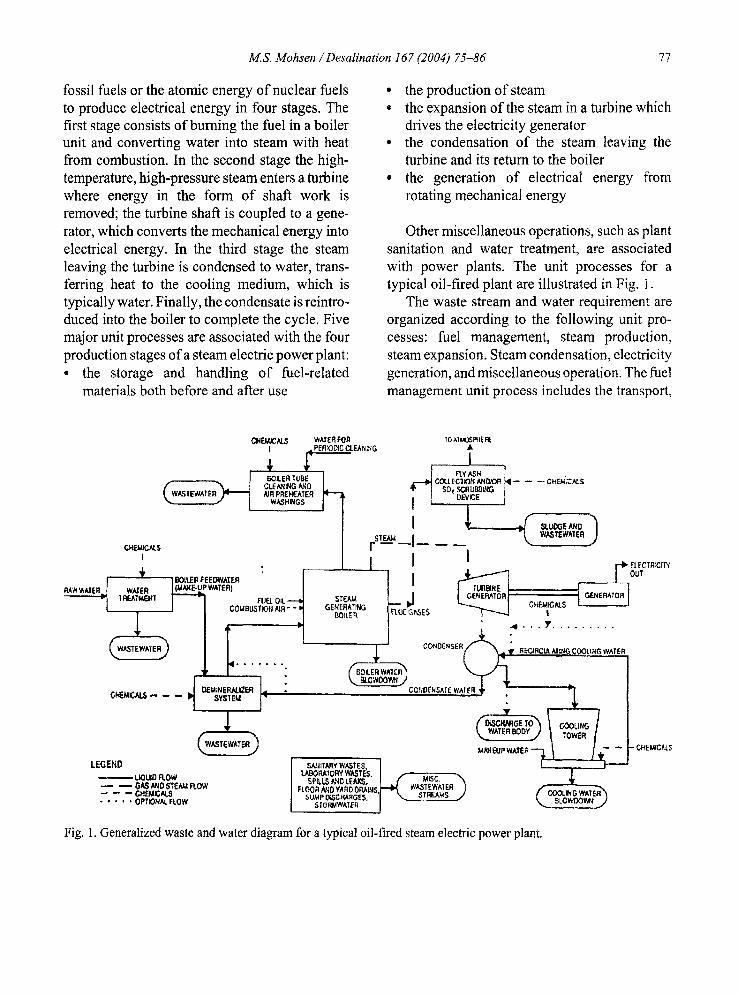
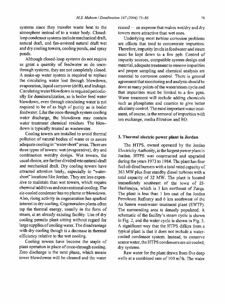
Other miscellaneous operations, such as plant sanitation and water treatment, are associated with power plants. The unit processes for a typical oil-fired plant are illustrated in Fig. 1.
The waste stream and water requirement are organized according to the following unit pro- cesses: fuel management, steam production, steam expansion. Steam condensation, electricity generation, and miscellaneous operation. The fuel management unit process includes the transport,
CHEMICALS WATER FOR I ,~PEfl ~IDIC CL ENI '-'iG
1 R ~ GO~ ER TUBE
,W CLE/',,."tIN G K~D ASTEWATE NR PREHEATER
WASHINGS
CH~ICAL$ I
G ItST EWATE R~
-----4--1. " "
CC'NOE~SER(
CONDENSATE WATEB
TO .',IuO~EER( A
A _ _ COLLECI~N ¢d'~O,*OR N - - -- -- CHE~,~.N.-$
SOz SCRUBDL~G / DEVICE j
STO,tl F - -
l I ! r* Ecr=
flECIRCUt AIN° COOLtNG WA|ER
SYS'I' Eld ~ . . . .
LEGEND I sudlr.,m~'w.,~r~z. ] L . .. ] - ' - - - ] I,.ABOI~'~T ORY W,~ TES. I ..... ..... L~UIDFI,OW SP~LSA ~lokrr~, I . /" , . . . . ~ : . . ^ ~.
-- -- G~,ANO$'TEAMFLOW FLOOnN;D¥.AtlDC, p..ALM$.,~I,,~ ..,,~j~T~I~N ) -- -- CHEMICALS SU~APO~CMA~GES, I ~ ~ , n ~
..... OPTIONXL R.OW SIORMWATER ,,
= CHEU~C~S
Fig. 1. Generalized waste and water diagram for a typical oil-fired steam electric power plant.
78 M.S. Mohsen / Desalination 167 (2004) 75-86
storage, and handling of fuel oil. Oil spills can result in significant power plant waste streams and water consumption. Spillage and subsequent wash-down can contaminate the plant drainage system and consume large amounts of water.
Power plants are usually designed to recycle condensed steam for boiler feedwater as means of conserving water. Efficient plant operation requires boiler feedwater to be highly pure. However, dissolved solids are concentrated in the recycled condensate as a result of evaporative water loss. To maintain total dissolved solids below allowable limits for boiler operation, a controlled amount is sometimes bled off. This volume, called boiler blowdown, is treated as wastewater and is replaced with high-purity make-up water.
Water treatment for make-up water typically includes suspended solids and hardness removal, scale and corrosion control, and demineralization. Suspended solids removal usually requires such operations as clarification and filtration. Hardness removal is typically accomplished by lime-soda softening, which requires the addition of lime and caustic soda. Ammonia and phosphate are typically added for corrosion control. Deminerali- zation usually involves ion exchange and mem- brane processes such as reverse osmosis (RO). Residue of all of these processes may flow to the wastewater treatment system along with the rejected brine water. The treatment sludges are typically land filled.
There are no maj or chemical effluents or water use requirements associated with the steam expansion process. However, the significance of the process lies in its effect on plant efficiency and, therefore, on the thermal discharge. When a water-steam cycle is used to convert steam heat to the mechanical work of turbines, the maximum theoretical efficiency that can be obtained is limited by the difference in temperatures at which the heat can be absorbed by the steam and dis- carded after passing through the turbines. Thus to achieve any degree of power plant efficiency, it is
inevitable that heat must be discharged from the plant to some compartment of the environment.
Condensers and cooling towers are key equip- ment in the power plants circulating water sys- tem. The steam condensation process can produce significant water demands and wastes if water- cooled condensation is employed. Air-cooled condensers do not require water or generate wastewater but have a very low cooling effi- ciency. The two most common types of water- cooled systems are once-through and closed-loop, the main difference being that once-through systems consume more water than do closed-loop systems. Once-through systems take cooling water from a natural source, pump it through the condenser, and discharge the heated cooling water to the same body of water from which it was drawn. The water temperature rise can be disruptive pollutant to the ecosystem of the water body.
Once-through systems may also pollute receiving waters with chemical residue. Chemi- cals may be added to the cooling water before it enters the condenser to prevent or minimize scaling, corrosion, and fouling in the condenser pipes. Chemicals added typically include phos- phate, lime, chromium, aluminum and zinc. It is also common practice to add some type of biocide, including chlorine, to the water to control the growth of slime. Residues of these chemicals will be discharged from the condenser with the cooling water.
If sufficient water for a once-through system is not available, cooling water must be recir- culated within the plant in a closed-loop condenser. Closed-loop water cooled condenser systems employ some form of cooling device, such as an artificial pond or a cooling tower, as an intermediate device to transfer waste heat to the atmosphere. The relatively cool water can then be recirculated in the condensers.
In addition to increased water conservation, closed-loop systems also effectively eliminate the problem of thermal pollution to aquatic eco-
M.S. Mohsen / Desalination 167 (2004) 75-86 79
systems since they transfer waste heat to the atmosphere instead of to a water body. Closed- loop condenser systems include mechanical draft, natural draft, and fan-assisted natural draft wet and dry cooling towers, cooling ponds, and spray ponds.
Although closed-loop systems do not require as great a quantity of feedwater as do once- through systems, they are not completely closed. A make-up water system is required to replace the circulating water lost through blowdown, evaporation, liquid carryover (drift), and leakage. Circulating water blowdown is required periodic- ally for demineralization, as is boiler feed water blowdown, even through circulating water is not required to be of as high of purity as is boiler feedwater. Like the once-through system cooling water discharge, the blowdown may contain water treatment chemical residues. The blow- down is typically treated as wastewater.
Cooling towers are installed to avoid thermal pollution of natural bodies of water or to assure adequate cooling in "water short" areas. There are three types of towers: wet (evaporative), dry and combination wet/dry design. Wet towers, the usual choice, are further divided into natural-draft and mechanical draft. Dry cooling towers have attracted attention lately, especially in "water- short" locations like Jordan. They are less expen- sive to maintain than wet towers, which require chemical additives and conventional cooling. The air-cooled condenser has no plume or blowdown. Also, rising activity in cogeneration has sparked interest in dry cooling. Cogeneration plants often tap the thermal energy, usually in the form of steam, at an already existing facility. Use of dry cooling permits plant sitting without regard for large supplies of cooling water. The disadvantage with dry cooling though is a decrease in thermal efficiency relative to the wet cooling.
Cooling towers have become the staple of plant operation in place of once-through cooling. Zero discharge is the next phase, which means tower blowdowns will be cleaned and the water
reused - - an expense that makes wet/dry and dry towers more attractive than wet ones.
Underlying most turbine corrosion problems are effects that tend to concentrate impurities. Therefore, impurity levels in feedwater and steam must be kept down to a few ppb. Control of impurity sources, compatible system design and material, adequate treatment to remove impurities and proper sampling and chemical analysis are essential to corrosion control. There is general agreement that monitoring and analysis should be done at many points of the water/steam cycle and that impurities must be limited to a few ppm. Water treatment will include adding chemicals such as phosphates and caustics to give better alkalinity control. The most important water treat- ment, of course, is the removal of impurities with ion exchange, media filtration and RO.
3. Thermal electric power plant in Jordan
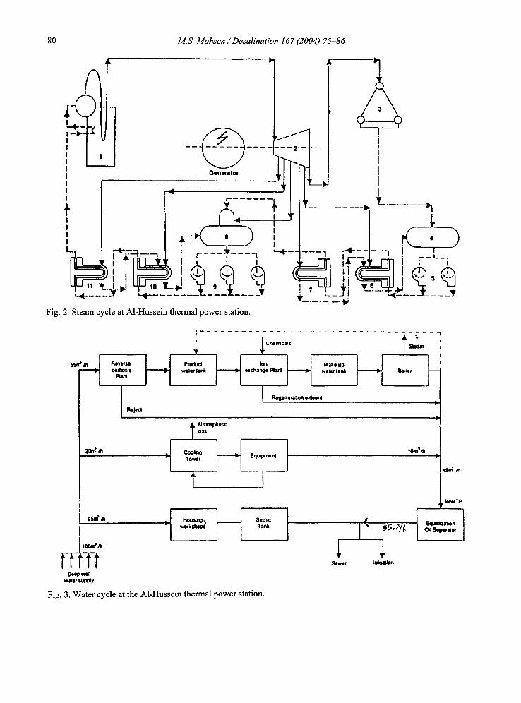
The HTPS, owned operated by the Jordan Electricity Authority, is the largest power plant in Jordan. HTPS was constructed and upgraded during the years 1973 to 1984. The plant has four fuel oil-fired burners with a total rated capacity of 363 MW plus four standby diesel turbines with a total capacity of 32 MW. The plant is located immediately southeast of the town of E1- Hashimiya, which is 3 km northeast of Zarqa. The plant is less than 1 km east of the Jordan Petroleum Refinery and 6 km southwest of the As Samra wastewater treatment plant (SWTP). The surrounding area is densely populated. A schematic of the facility's steam cycle is shown in Fig. 2, and the water cycle is shown in Fig. 3. A significant way that the HTPS differs from a typical plant is that it does not include a water- cooled condenser system. Instead, to conserve scarce water, the HTPS condensers are air cooled, dry systems.
Raw water for the plant drawn from five deep wells at a combined rate of 100 m3/h. The water
80 M.S. Mohsen / Desalination 167 (2004) 75-86
Gonerl lor
1 I I I I L . . . , 4 - - . . . . . ?h=,: + ,~ I ,~ . ~)', ;I ,~ , ~ - ~ " 't-.4~.~O ~ lo '
--4
- - - ~ t - - - - a r J r-
Fig. 2. Steam cycle at A1-Hussein thermal power station.
i /
w~
I I I I I
r
T_. . . . . . . . .
2 o ~ m
2Sin' m
IOOmt m
t- t-N Otep wea
wllet I ~ y
RIWt;$B Olmm~g
t~l,a
,c_... io: + _
, - I ! - I I - . , ° ! I ...... L- Witlllf laJl~ I ~.~ t II¢.halh~ql Pl31~ ~ Wltlllr ¢llrlk ~ ~141¢
I R~enem~n ,i~k~enl
T AlmOsl~,~
Ttwtt 1
t J
wOrkshopl Tank
Fig. 3. Water cycle at the A1-Hussein thermal power station.
tOm~/h
I ~, ~'"/~
I I 4S~ m
. . . . . J WWTP
E q, ml~za!Jon Seoaral¢~
M.S. Mohsen / Desalination 167 (2004) 75-86 81
is used as a coolant for bearings and other equipment, as boiler feed water, and for various plant services, including water supply for the HTPS housing estate. The water used to cool equipment is recirculated through a cooling tower.
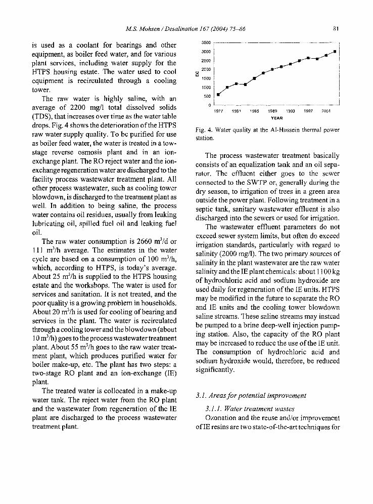
The raw water is highly saline, with an average of 2200 rag/1 total dissolved solids (TDS), that increases over time as the water table drops. Fig. 4 shows the deterioration of the HTPS raw water supply quality. To be purified for use as boiler feed water, the water is treated in a tow- stage reverse osmosis plant and in an ion- exchange plant. The RO reject water and the ion- exchange regeneration water are discharged to the facility process wastewater treatment plant. All other process wastewater, such as cooling tower blowdown, is discharged to the treatment plant as well. In addition to being saline, the process water contains oil residues, usually from leaking lubricating oil, spilled fuel oil and leaking fuel oil.
The raw water consumption is 2660 m3/d or 111 m3/h average. The estimates in the water cycle are based on a consumption of 100 m3/h, which, according to HTPS, is today's average. About 25 m3/h is supplied to the HTPS housing estate and the workshops. The water is used for services and sanitation. It is not treated, and the poor quality is a growing problem in households. About 20 m3/h is used for cooling of bearing and services in the plant. The water is recirculated through a cooling tower and the blowdown (about 10 m3/h) goes to the process wastewater treatment plant. About 55 m3/h goes to the raw water treat- ment plant, which produces purified water for boiler make-up, etc. The plant has two steps: a two-stage RO plant and an ion-exchange (IE) plant.
The treated water is collocated in a make-up water tank. The reject water from the RO plant and the wastewater from regeneration of the IE plant are discharged to the process wastewater treatment plant.
3500
3000
2500
2000
1500
1000
500
0 1977 1981 1985 1989 1993 1997 2001
YEAR
Fig. 4. Water quality at the Al-Hussein thermal power station.
The process wastewater treatment basically consists of an equalization tank and an oil sepa- rator. The effluent either goes to the sewer connected to the SWTP or, generally during the dry season, to irrigation of trees in a green area outside the power plant. Following treatment in a septic tank, sanitary wastewater effluent is also discharged into the sewers or used for irrigation.
The wastewater effluent parameters do not exceed sewer system limits, but often do exceed irrigation standards, particularly with regard to salinity (2000 rag/l). The two primary sources of salinity in the plant wastewater are the raw water salinity and the IE plant chemicals: about 1100 kg of hydrochloric acid and sodium hydroxide are used daily for regeneration of the IE units. HTPS may be modified in the future to separate the RO and IE units and the cooling tower blowdown saline streams. These saline streams may instead be pumped to a brine deep-well injection pump- ing station. Also, the capacity of the RO plant may be increased to reduce the use of the IE unit. The consumption of hydrochloric acid and sodium hydroxide would, therefore, be reduced significantly.
3.1. Areas for potential improvement
3.1.1. Water treatment wastes Ozonation and the reuse and/or improvement
of IE resins are two state-of-the-art techniques for
82 M.S. Mohsen / Desalination 167 (2004) 75-86
minimizing water treatment wastes that have been documented in the literature [11]. The use of ozone as a sole treatment for water is emerging as a reliable alternative to traditional multi-chemical treatment methods because it (1) effectively controls scale, corrosion and biogrowth; (2) con- serves water; and (3) eliminates the use, storage, and discharge of otherwise necessary treatment chemicals. Ozonation is, however, energy intensive.
An allotrope of oxygen, ozone is the strongest commercially available oxidizing agent. Unlike chlorination, ozonation produced no residuals. Instead, ozone has a very short half-life in water, with simple 02 as its decomposition product. Ozone is not stored for later use; it is immediately injected into the treated water as it is produced on-site by the ozone generator. The raw materials needed for generating ozone are air and electrical energy.
The disposal of IE resins used for process water demineralization is a growing concern. However, because spent IE resins typically retain at least half their original capacity, they can be reused in applications other than deminerali- zation. For example, the resins can be beneficially applied to soil. Adding spent IE resins to soil improve its cation-exchange capacity, thus enhancing the soil 's ability to retain fertilizer. The benefits are magnified during periods of rain and irrigation. At these times, soil nutrients are lost through leaching into groundwater and through run-off. Because soil has little or no natural IE capacity, these losses can be excessive. Plants are unable to absorb nutrients as fast as they leach from the soil. Farmers, in turn, add more fertilizer to replace that lost to run-off or leaching. Adding spent IE resins to cultivated soil helps overcome this cycle of waste. The resins act like a huge sponge that can retain nutrients until they are needed by the plants. However, it must be noted that these highly cross-linked-polymer resins are essentially non-biodegradable.
The cooling water waste and contaminated process water wastes can be treated by many different methods: • Isolate and separately treat waste streams, i.e.,
oily water from clean brines and domestic wastes.
• Reuse treated irrigation water in the processes. • Direct RO and IE and filtration backwash for
separate treatment. • Treat and reuse condensation. • Evaluate use of Wadi water as non-contact,
one-pass cooling water. • Minimize wash-down water usage and deter-
gent additives. • Consider treating domestic waste on-site using
the water discharge in the process. • Evaluate recycling RO in stages to enable
reuse in process. ° Deep-well injectbrines which are too costly to
treat further. • Reuse water from the equalization oil sepa-
rator. • Catch storm water, remove oil and solids and
reuse as boiler water feed.
The actual wastewater treatments can be sum- marized as filtration (media and RO), oil skim- ming, sewage treatment, flow control, and deep- well injection.
3.1.2. Water conservation
Water conservation improvements identified in the literature [12] apply to flue gas desulfuri- zation, blowdown and water treatment systems, and alternative water sources. Also, water con- servation can be realized through general process improvements.
3.2. Flue gas desulfurization system water conservation
Flue gas emissions control devices, par- ticularly wet lime and limestone scrubbers, are
M.S. Mohsen / Desalination 167 (2004) 75-86 83
large consumers of water. However, because they do not require high-purity water, they can receive low-quality water in recycled from, for example, a cooling tower blowdown; this low-quality water is otherwise typically considered wastewater. Also, the use of low-sulfur fuel oil will eliminate the need even to treat the emissions, thereby conserving the treatment water.
control the suspended solids level. Side stream treatment consists of treating a portion of the circulating water and returning it to the system. By-product streams, such as sludge or flitter backwash, are not returned to the system and their volume must be replaced with additional make-up water. Make-up water treatment is primarily lime- soda softening.
3.3. Blowdown system water conservation
Blowdown systems have the potential for water conservation through reuse. For example, since the boiler feedwater supply has the highest water quality requirements of any system in the power plant, boiler blowdown is generally of higher purity than the original source of supply. Thus, untreated boiler blowdown can efficiently be recycled for almost any other use in the plant.
Treated cooling tower blowdown also has the potential for reuse. It has been documented [11] to be a good source of make-up and misting water for flue gas desulfurization scrubbers and may also be used for bearing flush water and pump- seal water. Characteristically, the blowdown must go through a lime-softening process for treat- ment; RO or IE may also be appropriate.
Additionally, the frequency ofblowdown and its associated treatment can be minimized to conserve water. However, there are upper limits at which it is not possible or practical to continue operating the boiler or cooling tower without blowdown due to excessive amounts of corrosion scaling and fouling from high concentrations of certain contaminants in the recirculating water. While the levels at which it is practicable to operate can be raised by using make-up water treatment, corrosion-resistant materials, and scaling, corrosion and fouling inhibitors, there are still upper bounds to the permissible cycles of water due to ion concentration.
One way to obtain the maximum cycles of water is by treatment of make-up water and recir- culating it. Side stream filtration can effectively
3.4. Water treatment system water conservation
RO demineralization systems have also been targeted as a means of water conservation. These systems typically divert approximately 25% of boiler feedwater flow to the drain as concentrated brine. A system has been devised that recovers all of the RO effluent stream for partial make-up to the cooling tower. The water that is now being pumped to the sewer and used for irrigation could be treated similarly to return a high percentage of it to the system. Ultimately the brine backwash from the RO unit could be deep-well injected.
3.5. Alternative water sources
One way to conserve water is to generate process water sources that would otherwise be considered wastewater. For example, a few power plants have utilized seawater or sewage treatment plant effluent as make-up water. In this case then, the effluent from the SWTP would be a source of plant water.
Both municipal sewage effluent and on-site sanitary wastewater can be recycled for make-up water. In some instances, more advanced treat- ment is required to remove nitrogen and phos- phorous or reduce suspended solids and BOD to very low levels. These treatment techniques supplement conventional municipal treatment of effluents with chlorination or ozonation.
The SWTP may discharge water that is either directly useable or useable after simple treatment in the power plant. The quality of this discharge is critical. If the sewage treatment plant effluent
84 M.S. Mohsen / Desalination 167 (2004) 75-86
is sufficiently low in salinity, consideration should be given to the use of the effluent as cool- ing water in the power plant. The water needs to be low in BOD as well so that the power plant would not need to construct its own biological treatment facility to treat the incoming sewage plant water. The possibilities of conserving the sewage treatment plant water by using it in the power plant can be evaluated technically and economically.
4. Present wastewater disposal
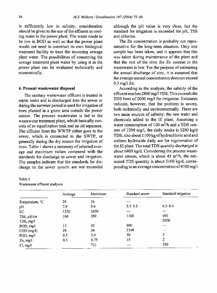
The sanitary wastewater effluent is treated in septic tanks and is discharged into the sewer or during the summer period is used for irrigation of trees planted in a green area outside the power station. The process wastewater is led to the wastewater treatment plant, which basically con- sists of an equalization tank and an oil separator. The effluent from the WWTP either goes to the sewer, which is connected to the SWTP, or generally during the dry season for irrigation of trees. Table 1 shows a summary of selected aver- age and maximum values compared with the standards for discharge to sewer and irrigation. The samples indicate that the standards for dis- charge to the sewer system are not exceeded
although the pH value is very close, but the standard for irrigation is exceeded for pH, TSS and chlorine.
The Zn concentration is probably not repre- sentative for the long-term situation. Only one sample has been taken, and it appears that this was taken during maintenance of the plant and that the rest o f the time the Zn content in the wastewater is low. For the purpose of estimating the annual discharge of zinc, it is assumed that the average annual concentration does not exceed 0.3 mg/1 Zn.
According to the analysis, the salinity of the effluent reaches 2800 mg/1 TDS. This exceeds the TDS limit of 2000 mg/1 for irrigation. Estimates indicate, however, that the problem is severe, both technically and environmentally. There are two main sources of salinity: the raw water and chemicals added to the IE plant. Assuming a water consumption of 100 m3/h and a TDS con- tent of 2200 mg/1, the daily intake is 5280 kg/d TDS; also about 1100 kg of hydrochloric acid and sodium hydroxide daily are for regeneration of the IE plant. The total TDS quantity discharged is about 6400 kg/d. Considering the process waste- water stream, which is about 45 m3/h, the esti- mated TDS quantity is about 5100 kg/d, corres- ponding to an average concentration of 4700 mg/1
Table 1 Wastewater effluent analyses
Average Maximum Standard sewer Standard irrigation
Temperature, °C 29 36 - - - - pH 7.9 9.4 5.5-9.5 6.5-8.4 EC 1250 2650 - - - - TSS, #S/cm 104 389 1100 100 TDS, mg/1 2000 BOD, mg/1 13 43 800 - - COD (mg/l) 28 64 2100 - - FOG, mg/1 0.5 2.0 50 5 Zn, mg/l 0.3 6.75 15 2 C1, mg/l 711 - - 350
M.S. Mohsen / Desalination 167 (2004) 75-86 85
f9
Reverse ~ - - - osmosis
plant
Reject
|
[ ;Chemicals T
water tank exchange plant Make up
water tank
Regeneration effluent
Bo!e:i 20m3/h
~ Atmospheric l o s s
Cooling " Tower
1'
Equipment
25m3/h t Housing workshops
100m3/h
Septic Tank
I
Sewer
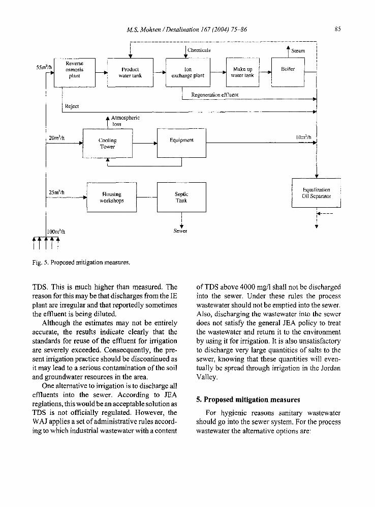
Fig. 5. Proposed mitigation measures.
10m3/h
Equalization Oil Separator
[
I
TDS. This is much higher than measured. The reason for this may be that discharges from the IE plant are irregular and that reportedly sometimes the effluent is being diluted.
Although the estimates may not be entirely accurate, the results indicate clearly that the standards for reuse of the effluent for irrigation are severely exceeded. Consecquently, the pre- sent irrigation practice should be discontinued as it may lead to a serious contamination of the soil and groundwater resources in the area.
One alternative to irrigation is to discharge all effluents into the sewer. According to JEA reglations, this would be an acceptable solution as TDS is not officially regulated. However, the WAJ applies a set of administrative rules accord- ing to which industrial wastewater with a content
of TDS above 4000 mg/l shall not be discharged into the sewer. Under these rules the process wastewater should not be emptied into the sewer. Also, discharging the wastewater into the sewer does not satisfy the general JEA policy to treat the wastewater and return it to the environment by using it for irrigation. It is also unsatisfactory to discharge very large quantities of salts to the sewer, knowing that these quantities will even- tually be spread through irrigation in the Jordan Valley.
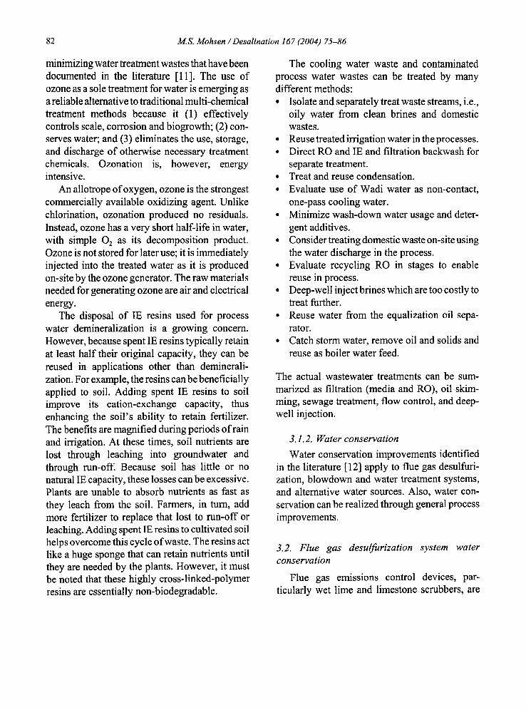
5. Proposed mitigation measures
For hygienic reasons sanitary wastewater should go into the sewer system. For the process wastewater the alternative options are:
86 M.S. Mohsen / Desalination 167 (2004) 75-86
• to use alternative water sources • to introduce cleaner technology which will
reduce the use of chemicals in the plant • to separate and treat the wastewater • to use alternative methods of disposing of the
wastewater
It has been considered to take water from the JEA Azraq-Amman water transmission line, which is 3.8 km away. As this water has a lower salinity level than the HTPS raw water wells, the consumption of chemicals in the IE unit would be reduced to about one-third. The consumption of chemicals for regeneration of the IE plant may be reduced to one-quarter if a third stage is added to the RO unit. It is recommended that the highly saline wastewater streams from the HTPS and from the Jordan Petroleum Refinery are com- bined and that the wastewater is injected into a deep well drilled for this purpose to approximatly 1100 m depth. In the HTPS, the wastewater system should be modified to separate the saline streams from the RO and IE units and the cooling tower blowdown, and these should be pumped into a new pipeline to a brine injection pumping station to be located at the the Jordan Petroleum Refinery. The proposed measures are shown in principle in Fig. 5. The consumption of chemicals is reduced from about 1100 kg/d to 300 kg/d. About 5100 kg/d TDS (salts and chemicals) will no longer contaminate the soil and endanger the ground water reservoir. Instead, the saline waste- water will be injected into the deep saline strata.
6. Conclusions
Relative to other thermal electric power plants using fuel oil in an arid environment, there appears to be some significant potential for water conservation at the HTPS. There is significant water pumped from the plant to the sewage plant and irrigation. Much of this wastewater could be treated by filtration, including RO, and recycled in the plant as process water. The salty filtration
and IE backwash here are two sources of dis- charge from the sewage treatment plant could potentially be recycled into the plant.
Water can very likely be conserved in the power plant by good operating practices such as preventative maintenance, good housekeeping, spill prevention, controlled storm run-off, clean- ing techniques using minimum water, and a good training program to ensure program success.
Since water conservation is essential in Jordan, long-term plans should include considera- tion of changing the basic steam turbine tech- nology to either the combined system or gas- and/ or diesel-driven turbines at this power plant.
It is recommended increasing the capacity of the RO plant, thereby reducing the use of the IE unit. Thus, the consumption of hydrochloric acid and sodium hydroxide is reduced significantly.
References
[1] H.A. Abu Qdais and F. Batayneh, Desalination, 150 (2002) 99.
[2] O.R. A1-Jayyousi and M.S. Mohsen, Desalination, 139 (2001) 237.
[3] M.D. Afonso, J.O. Jaber and M.S. Mohsen, Desali- nation, 164 (2004) 157.
[4] M.S. Mohsen and O.R. Al-Jayyousi, Desalination, 124 (1999) 163.
[5] J.O. Jaber and M.S. Mohsen, Desalination, 136 (2001) 83.
[6] M.S. Mohsen and J.O. Jaber, Desalination, 152 (2002) 281.
[7] M.D. Afonso, A.M. Brites Alves and M.S. Mohsen, Desalination, 149 (2002) 153.
[8] M.D. Afonso and R.B. Yanez, Desalination, 139 (2001) 429.
[9] B. Durham, M.M. Bourbigot and T. Pankratz, Desaination, 138 (2001) 83.
ll0] A.J. Karabelas, S.G. Yiantsios, Z. Metaxiotou, N. Andritos, A. Akiskalos, G. Vlachopoulos and S. Stavroulias, Desalination, I38 (2001) 93.
[1 i] H. Zhou and D.W. Smith, J. Environ. Eng. Sci, 1(4) (2002) 247.
[12] C.D. Livengood and J.M. Markussen, Nox Control VII Conference, USA, 1994, pp. 1-18.