tremor problem statement 2012
TRANSCRIPT

8/4/2019 Tremor Problem Statement 2012
http://slidepdf.com/reader/full/tremor-problem-statement-2012 1/8
TREMOR, TECHKRITI 2012
PROBLEM STATEMENT
Design and construct a G+6 (seven) storey RC building model, to function as a residential building with at least
four apartments on each floor, to be located in New Delhi, according to the following terms and conditions.
1. Configuration of Models
1.1Baseboard: The model shall be constructed on a square baseboard provided by the organizing team. The
baseboard, Mb, shall be weighed and recorded before the construction of the model. A clearance of 25mm must
be left around the edges of the baseboard such that the model can be fixed easily handled onto the 1-
Dimensional Earthquake Simulator at Structural Engineering Laboratory.
1.2 Holes in the Baseboard: The screws on the shake table are at center to center distance of 25cm. Hence the
baseboard provided will carry holes drilled accordingly. Hence it is highly advisable that the participants do not
disturb these holes during construction to ensure that their structures can be tested.
1.3 Number of Floor: There is no restriction on the number of bays in any direction. Figure A and B show one
and two bay systems respectively. The building will have 7 storeys and hence 7 floors excluding the baseboard,
which may be supported in any way desired. A flat roof shall be treated as a floor. The baseboard can be used as
the ground floor of the model where no additional weights (refer section 3.4) will be applied.
1.4 Clear distance: As shown in Figures A and B, the distance between the top surface of the slab of any floor
and the bottom of the girder of the floor above it (i.e. the clear distance) must be a minimum of 12 cm and a
maximum of 15 cm. The height of the lead weights (refer section 3.4) on any floors of the model is not counted
as part of the floor for minimum clear distance calculation.

8/4/2019 Tremor Problem Statement 2012
http://slidepdf.com/reader/full/tremor-problem-statement-2012 2/8
1.5 Location of Columns: The minimum clear spacing between the columns of the structure should be 12cm.
and the responsibility of placing columns in such a way that the lead weights (supposed to act as dead load,
section 3.4) can be placed in each room of every apartment lies with the participant. They may be placed in the
interior but it should be ensured that the weights can be mounted easily. Also, placing columns in the interior
should not obstruct the usable area or in other words the columns should be placed only at the edges of partition
walls or shear walls. Figure C shows a typical arrangement of columns along with shear walls.
Fig. C: Plan views showing the positions of columns
1.6 Area of floor: Each of the seven floors is to be divided into four 2-BHK apartments plus the addition space
for staircase, elevator shaft and a gallery interconnecting the apartment with the staircase and elevators. Each
apartment must have a balcony. For ease of construction and accessibility of the entire floor area the living
room and the kitchen can be merged as is done in most of the economic apartments these days. The floor area
of each floor is the area enclosed by the four apartments and the outermost columns including the space taken
up by the columns except for the balcony which will be included in the floor area.
1.7 Size of Structural Members: Maximum size of structural members are:-
Bracing: 10mm×2mm
Beam: 10mm×4mmColumn: 10mm×6mm
1.8 Shear Wall: Shear walls are optional. There is no restriction on the length of the shear wall; however its
thickness should not exceed 8mm.
Figure D: Arrangement of shear walls

8/4/2019 Tremor Problem Statement 2012
http://slidepdf.com/reader/full/tremor-problem-statement-2012 3/8
1.9 Non-structural elements:
1.9.1Walls: Each floor shall be divided into at least four 2-BHK apartments using partition walls (two
bedrooms, living room, kitchen and a bathroom) and a gallery connecting them with elevator and staircase. The
partition walls used in each apartment shall have a maximum thickness of 4mm. For the sake of accessibility the
curtain walls can be omitted.
1.9.2 Elevators:The building must have at least two elevators connecting ground floor to all the floors. The minimum cross
section area of the elevators must be 25cm2.
1.9.3 Staircase:
There must be at least one set of staircases connecting each floor to be constructed from the ground floor. The
staircase may be represented by an incline on each floor. The minimum thickness of the staircase must be at
least 5cm.
1.9.4 Gallery:
The apartments, staircases and the elevators must be interconnected by a continuous gallery of a minimum
width 5cm.
1.9.5 Glass Work:
By using transparent wrapping paper one can specify the use of glasswork to maximize the amount of sunlight
in the gallery to minimize electricity consumption for lighting purpose.
2. Materials
The participating teams shall only the materials provided by the organizing team to construct their models. The
specifications and quantities of the materials are listed in Table 2.1 below.
Table 2.1 Materials to be provided
Materials Specifications Quantity
Timber strips 1000mm × 10mm × 2mm 250 sticks
Cotton string Cotton Twines No. 2m
Baseboard 600mm × 600mm ×10mm 1
Plywood (Shear walls) 1000mm × 600mm × 8mm 2
Plywood (floor slabs) 600mm × 600mm × 6mm 7
Plywood (partition walls) Thickness – 4mm, Area – 40000cm2
1
Fevicol - 400gm
Sandpaper - -
3. Construction of Models
3.1 Exterior (curtain) and Interior (partition) Walls: Each of the four apartments must have 2 bedrooms,
living room, kitchen (merged with living room) and at least one bathroom and a balcony. Each of these rooms
should be separated with partitions walls having slots for doors. The curtain walls can be omitted for ease of
construction and mounting. The rooms with curtain walls as one (or more) of their walls must have windows
with minimum area of 25% area of the wall (or larger wall, in case of multiple walls) for each room. The
window area may be distributed, in case of multiple curtain walls as walls of a room, among the walls. Walls

8/4/2019 Tremor Problem Statement 2012
http://slidepdf.com/reader/full/tremor-problem-statement-2012 4/8
must separate each apartment from the hallway of each floor and staircase and lift on each floor. Also the
windows should lie in the region between 2cm from the bottom slab and 3cm from the upper slab. The windows
may be single slot or double slot with a column in between as shown.
Window with a column in between Window without a column in between
3.2 Exterior clearance:
There is no restriction on the amount of bracing on any face of any floor. The projection of the bracing could
cover the entire perimeter of the floor below. However, the bracing should be managed such that any room
with a peripheral wall of the building as one of its wall has a minimum of 25% of its area free in the form of
a single or a multiple window without any obstruction free for windows.
3.3 Interior clearance:
In order to eliminate the obstruction to usable space on any floor or in any of the apartments. No bracings
are allowed to be placed inside an apartment. However they may be used in the hallway of each floor.
3.4 Additional Weights: Addition weights will applied to the model in every room of each of the four
apartments on every storey and as counterweight for the elevators to simulate the dead load on that acts on
a real structure. The lead weights will be applied by inserting a screw through the hole in the lead weight
which will go through the pre-drilled holes in the slab, and securely fix it to the slab.
Holes could be drilled into the floor slabs during the construction stage at strategic points as decided by the
participants.
Every floor of the model, already divided into rooms, will be applied lead weights onto according to the itsresidential area. The participants must ensure that lead that the architecture and construction of the structure
is such that weights can be applied in each room. It is advisable that the loads be placed symmetrically on
the slabs.
Each lead weight weighs 865 grams and has a diameter of 60mm and height of 28mm.
The floor area of each floor is the area enclosed by the four apartments and the outermost columns
including the space taken up by the columns and the balcony which will be included in the floor area.
Counter weight will be applied for the elevator using a string from the top floor.
Floor area
(cm2)
No. of lead weights
625-699 7
700-774 8
775-849 9
850-924 10
925-1024 11
1025-1124 12
and so on.
8/4/2019 Tremor Problem Statement 2012
http://slidepdf.com/reader/full/tremor-problem-statement-2012 5/8
For the application of the lead weights to simulate the counterweights of the elevators participants are
required to drill two holes in the top floor slab and slots of minimum area 25 cm2
in all the other slabs. This
is done so that a string can be applied with weights tied on one end, running through the slots in all the
floors passing through the holes in the upper slab, running down through all the slots and tied to the
foundation on the other end, effectively establishing the suspension of weights through a pulley mechanism
4 Competition:
4.2 Mounting of the Model and Fixing of Steel Weights: The organizing team will arrange for each model to
be securely mounted onto the Uniaxial Shake Table and to apply the lead weights to the floors of each
model.
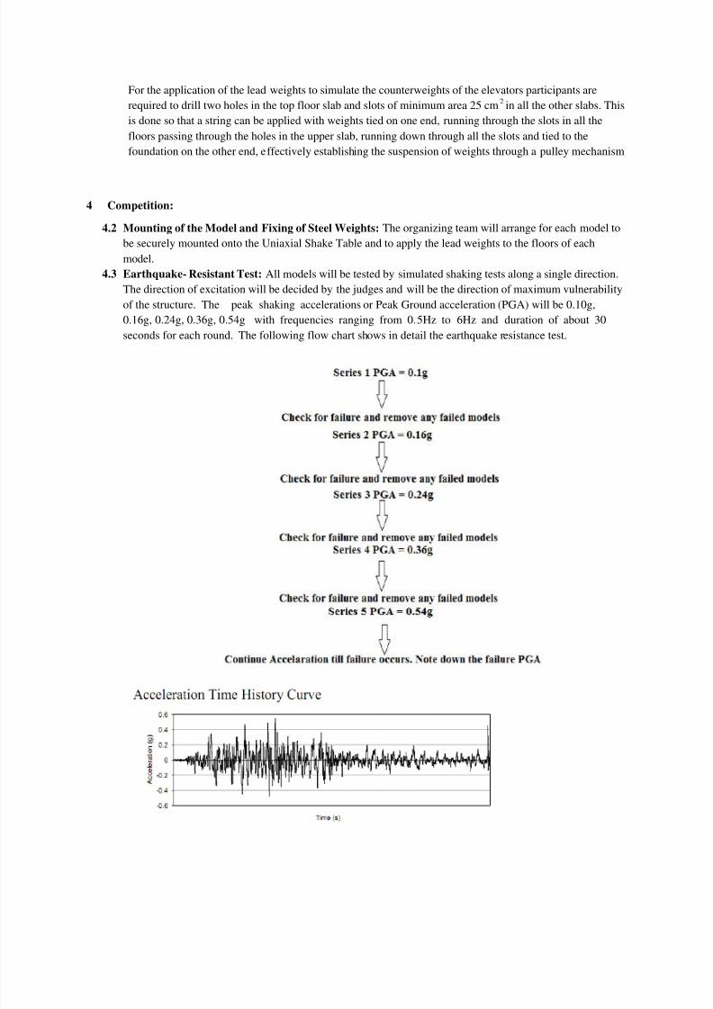
4.3 Earthquake- Resistant Test: All models will be tested by simulated shaking tests along a single direction.
The direction of excitation will be decided by the judges and will be the direction of maximum vulnerability
of the structure. The peak shaking accelerations or Peak Ground acceleration (PGA) will be 0.10g,
0.16g, 0.24g, 0.36g, 0.54g with frequencies ranging from 0.5Hz to 6Hz and duration of about 30
seconds for each round. The following flow chart shows in detail the earthquake resistance test.

8/4/2019 Tremor Problem Statement 2012
http://slidepdf.com/reader/full/tremor-problem-statement-2012 6/8
4.4 Failure of Building Model: A model is deemed to have failed under following conditions:
Complete collapse of the model.
Collapse of one or more storeys.
The model has deformed excessively (maximum lateral permanent deformation is more than
2% of the gross building height).
Half or more than half of the columns are detached from the base board.
Any of lead weights falling off from one of the floors.
4.5 Scoring Method: The scoring method is primarily dependent on the economy of building and is given by
the following expression:
S: Score
I: Income of the building which will be calculated by the following expression:
I=K*A
A: Area of the floor freely available for residential usage in cm2
K= 1000Rs/cm2
(for 1-5 floors)
1100Rs/cm2
(for 6th floor)
1200Rs/cm2
(for 7th floor)
C: Cost of the building will be based on the mass of the material used and the rate of the material will be
taken as 1500Rs/gm
PGA: Peak Ground Acceleration at which the building fails (refer 4.3)
R: Repair cost (R) = 1500*m (m- mass of the structural element that failed in gm)
PGAr: Peak Ground Acceleration at which the above described structural element in the repair cost fails.
4.6 Bonus: The bonus will be given on three bases:
Additional features implemented in the building: (BE)
Energy-efficiency :
1. Solar Equipments: This will involve the construction of an eight floor which will not
be considered for income, however will house solar equipments like the solar water
heater and any other equipment.
To avail this bonus, the ratio (K1) of energy saved by solar water heater to total energy
consumption (assuming all the residents use electric geyser) has to be calculated. The
bonus will be quantified as
BE1 = S + S×K1
2. Rain water Harvesting: Drainage system for rain water harvesting which will direct
the water into a storage tank through a piping system.
To avail the bonus for water harvesting the participants are required to construct the
drainage as well as the piping system to direct the rainwater to the storage tanks.
Through detailed calculations the participants have to find the ratio (K2) of the volume
of water saved by harvesting to the volume of water used by the residents per year.
The bonus will be quantified as
BE2 = S + S×K2

8/4/2019 Tremor Problem Statement 2012
http://slidepdf.com/reader/full/tremor-problem-statement-2012 7/8
3. Terrace garden: This will help to keep the apartments in the top floor cool and will
help to reduce energy consumption for cooling. This will lead to the application of
dead load on the eighth floor. Number of lead weights applied will depend on the area
and location of the terrace garden, and will be one-third (or least integer greater) of
the distribution given in section 3.4. For eg. for a terrace garden of area 860cm2
4
lead weights will be applied.
The bonus will be quantified as:
BE3 = S + 750Rs/cm2×A
…. where A is the area of the terrace garden in cm2.
Penthouses on top two floors:
The top two floors can be converted into penthouses (luxury apartment). The price of the
penthouse will be calculated 1300Rs/cm2
and the number of lead weights to be applied as
given by section 3.4 will be increased by 4.
Oral presentation:
There will be an oral presentation for 5 minutes for every team where they will explain their
structural design. The jury will be given 2 minutes to ask questions to the team. The presentationmust address the main design issues in the model and any innovation that is incorporated. The
rankings of the team in the presentation will decide the bonus score for 20 teams by the following
equation:
S: Score
R: Rank in the presentation given by the jury
This implies that the 1st
ranked team out of 20 teams will get 25% of his score as bonus.
Prediction of base shear and the value of PGA up to which he structure will not fail:
This PGA is to be reported in by the team in the presentation itself, failing which they shall be
disqualified for this bonus. The value actual represents the actual PGA at which the structure will
fail and the value expected is the value predicted by the participants.
Bonus for the calculated values will be given by the following:
4.7 Final Score: Final score (FS) will be given by the following
FS = (S +BE + B1+ B2 )
4.7 Violation Penalty: Teams will be penalized if:
Using other materials that are not specified in the rules.
The Dimensions are not adhered to.

8/4/2019 Tremor Problem Statement 2012
http://slidepdf.com/reader/full/tremor-problem-statement-2012 8/8
The constructed structures deviate from the abstracts submitted leading to the wastage of material
provided.