trends in high efficiency hvac packaged products...
TRANSCRIPT

Trends in High Efficiency HVAC Packaged
Products
May 2012

© 2012 Carrier Corporation
Packaged commercial HVAC equipment and application overview
Trends in high efficiency commercial packaged products
Full load mechanical improvement challenges
The importance of part load efficiency
Technology enablers for energy savings
Multi-speed technology
Technology enablers for shedding peak load
Demand Controlled Ventilation
Energy Recovery
Thermal Storage in packaged systems
Gas Heat on Packaged units: energy saving strategies (heating)
AGENDA
© 2012 Carrier Corporation
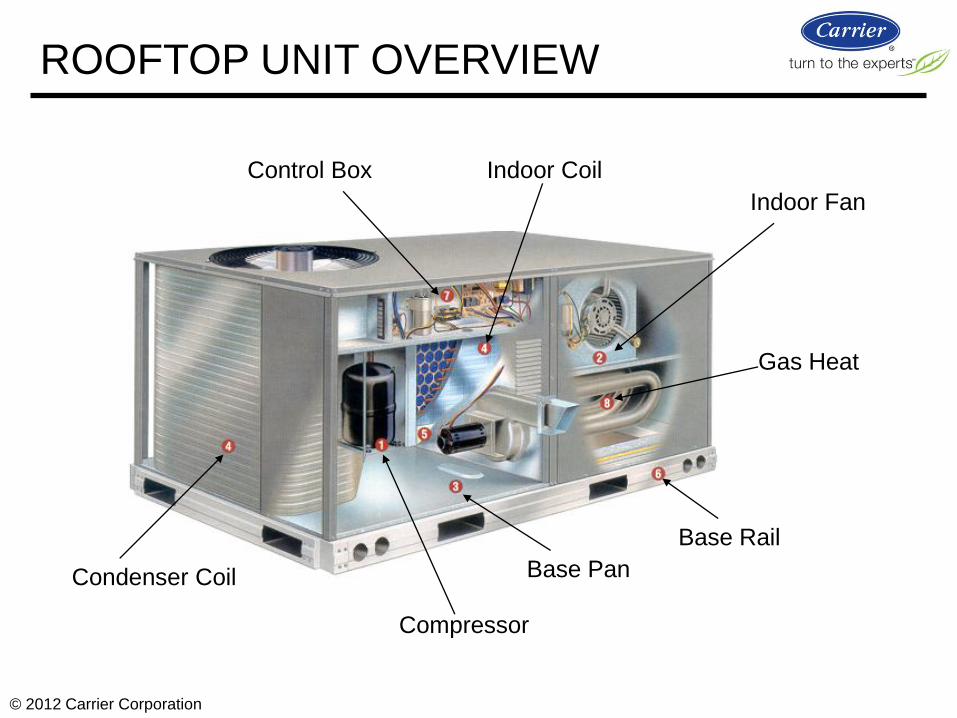
Compressor
Indoor Fan
Base Pan
Base Rail
Condenser Coil
Indoor Coil Control Box
Gas Heat
ROOFTOP UNIT OVERVIEW

© 2012 Carrier Corporation
Return Supply
Eva
po
rato
r
Blower
Power Exhaust (if equipped)
Barometric relief/exhaust
Heat Section
ROOFTOP UNIT OVERVIEW

© 2012 Carrier Corporation
PACKAGED UNIT APPLICATIONS

© 2012 Carrier Corporation
AHRI – independent, 3rd party verification of unit performance. Ensures
manufacturer’s performance claims are accurate and rated uniformly,
enabling fair comparisons.
AHRI CERTIFICATION

© 2012 Carrier Corporation http://www.ahrinet.org/
AHRI CERTIFICATION

© 2012 Carrier Corporation
Packaged commercial HVAC equipment and application overview
Trends in high efficiency commercial packaged products
Full load mechanical improvement challenges
The importance of part load efficiency
Technology enablers for energy savings
Multi-speed technology
Technology enablers for shedding peak load
Demand Controlled Ventilation
Energy Recovery
Thermal Storage in packaged systems
Gas Heat on Packaged units: energy saving strategies (heating)
AGENDA

© 2012 Carrier Corporation
Significant improvements have been made in overall building efficiency as
well as Packaged Rooftop Efficiencies
EFFICIENCY IMPROVEMENTS
Significant improvement has also been
made for rooftop efficiencies, but we are
approaching “Max-Tech” for EER.
source: PNNL ASHRAE 90.1 Determination

© 2012 Carrier Corporation
EFFICIENCY IMPROVEMENTS
7
8
9
10
11
12
13
14
15
16
<5 tons 5 to 11.25 tons 11.25 to 20 tons 20 to 63.3 tons
ASHRAE 90.1-1989 (Pre-2001)
ASHRAE 90.1-2010
CEE Tier 1
CEE Tier 2
PAC limits shown YAC subtract 0.2
SEER IEER
7
8
9
10
11
12
13
5 to 11.25 tons
11.25 to 20 tons
20 to 63.3 tons
EER
ASHRAE 90.1-1989 (Pre-2001) ASHRAE 90.1-2010
CEE Tier 1
CEE Tier 2

© 2012 Carrier Corporation
Full Load
Design Point
Historic focus has been on full load efficiency - but that is less than 1% of the
operating hours.
Full load is important from peak kW but part load is where most of the hours are .
Also, most units are oversized by at least 10%
Latent control in humid zones contributes to increased power consumption in part
load operation.
The plot shows a
typical hours load
profile for an office
building: ambient
temperature vs load.
source: PNNL ASHRAE 90.1 Determination Benchmark Model
PART LOAD VS FULL LOAD
© 2012 Carrier Corporation
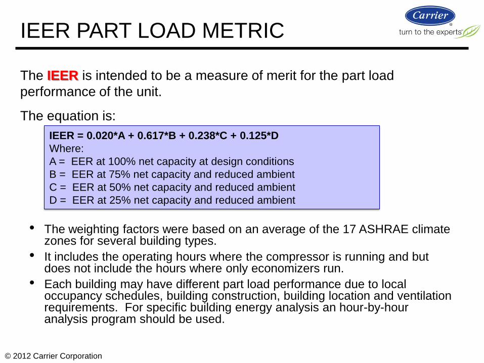
The IEER is intended to be a measure of merit for the part load
performance of the unit.
The equation is:
IEER PART LOAD METRIC
IEER = 0.020*A + 0.617*B + 0.238*C + 0.125*D
Where:
A = EER at 100% net capacity at design conditions
B = EER at 75% net capacity and reduced ambient
C = EER at 50% net capacity and reduced ambient
D = EER at 25% net capacity and reduced ambient
• The weighting factors were based on an average of the 17 ASHRAE climate zones for several building types.
• It includes the operating hours where the compressor is running and but does not include the hours where only economizers run.
• Each building may have different part load performance due to local occupancy schedules, building construction, building location and ventilation requirements. For specific building energy analysis an hour-by-hour analysis program should be used.

© 2012 Carrier Corporation
Packaged commercial HVAC equipment and application overview
Trends in high efficiency commercial packaged products
Full load mechanical improvement challenges
The importance of part load efficiency
Technology enablers for energy savings
Multi-speed technology
Technology enablers for shedding peak load
Demand Controlled Ventilation
Energy Recovery
Thermal Storage in packaged systems
Gas Heat on Packaged units: energy saving strategies (heating)
AGENDA
© 2012 Carrier Corporation
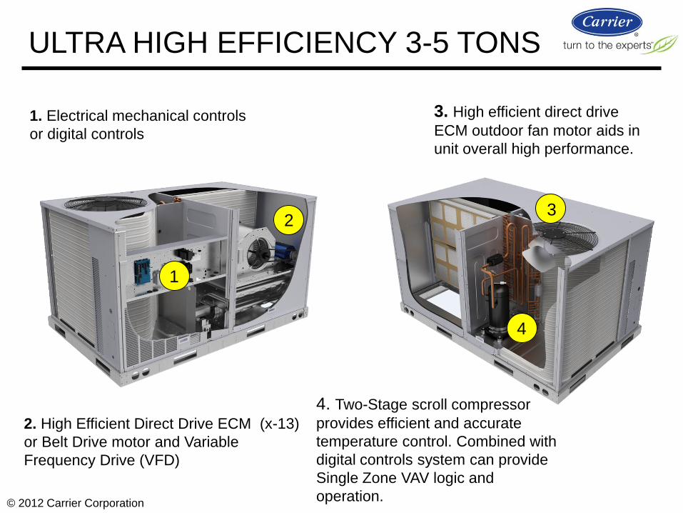
1. Electrical mechanical controls
or digital controls
2. High Efficient Direct Drive ECM (x-13)
or Belt Drive motor and Variable
Frequency Drive (VFD)
4. Two-Stage scroll compressor
provides efficient and accurate
temperature control. Combined with
digital controls system can provide
Single Zone VAV logic and
operation.
3. High efficient direct drive
ECM outdoor fan motor aids in
unit overall high performance.
1
2 3
4
ULTRA HIGH EFFICIENCY 3-5 TONS

© 2012 Carrier Corporation
ASHRAE 90.1 2010
Section: 6.4.3.10.b
ASHRAE Standard Summary:
As of January 1, 2012 all direct expansion Air Conditioners
& Air Handlers >110k+ capacity serving single zones shall
have two speed or variable speed drive indoor fan control.
At cooling demands less than or equal to 50%, the supply
fan controls shall be able to reduce the airflow to no greater
than the larger of the following: 1. Two-Thirds of the full fan speed or,
2. The volume of outdoor air required to meet the ventilation requirements of
Standard 62.1
Carrier
Indoor Fan Motor Belt Drive 2 Speed
1st Stage Cooling = Fan at 67%
1st and 2nd Stage Cooling = Fan at 100%
Any Heating = Fan at 100%
(VFD) Speed Controller
Fan Automatically Adjusts To Unit
Operation Per New Standard
Ventilation Only = Fan at 67%
MULTI SPEED INDOOR FAN

© 2012 Carrier Corporation
Based on annual estimated electric energy savings utilizing Carrier’s Hourly Analysis (HAP) Program v4.6.
Based on cooling and ventilation fan runtime hours using ASHRAE 90.1 office application, default
schedule, weather, and building data. Carrier model 48/50TC*D12. All locations except Los Angeles
evaluated with a single dry bulb economizer, Los Angeles evaluated with differential enthalpy economizer.
MULTI SPEED INDOOR FAN

© 2012 Carrier Corporation
Packaged commercial HVAC equipment and application overview
Trends in high efficiency commercial packaged products
Full load mechanical improvement challenges
The importance of part load efficiency
Technology enablers for energy savings
Multi-speed technology
Technology enablers for shedding peak load
Demand Controlled Ventilation
Energy Recovery
Thermal Storage in packaged systems
Gas Heat on Packaged units: energy saving strategies (heating)
AGENDA
© 2012 Carrier Corporation
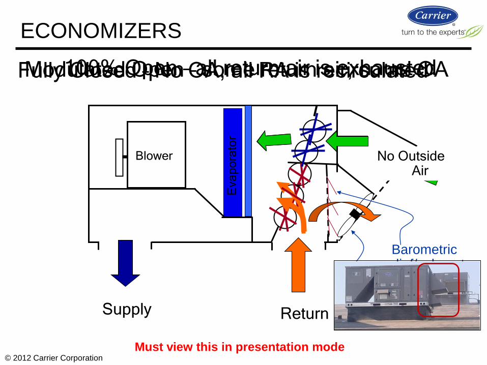
100% Open – all return air is exhausted
Return Supply
Eva
po
rato
r
Blower
Modulated Open – some return air, some OA
No Outside Air
Fully Closed – No OA, all RA is recirculated
Power Exhaust (if equipped)
Barometric relief/exhaust
Must view this in presentation mode
ECONOMIZERS

© 2012 Carrier Corporation
Sliding panel OA Dampers
ECONOMIZERS
Alternate intake options

© 2012 Carrier Corporation
Tampa, FL Syracuse, NY
ECONOMIZERS
Free cooling opportunities

© 2012 Carrier Corporation
Building Ventilation for area
+ Occupancy Ventilation for people
= Total ventilation rate
Commercial building code requires continuous ventilation
when occupied
Economizers with DCV can break the OA CFM into these
two parts and reduce the ventilation load on the HVAC
system, unless required by actual occupancy load.
ECONOMIZER DCV SAVINGS

© 2012 Carrier Corporation
Purple = “demand controlled” Green =“constant” Difference between the two equates to significant savings.
Bottom Line… CO2 is a good “people meter”
People exhale CO2 at concentrations of 4%
(40,000 ppm)
Normal room concentrations are ~ 400 - 1200
ppm
As a gas, CO2 diffuses and equalizes rapidly
throughout a room
CO2 production by people is very predictable
based on activity level…doubling the people in a
room will double the CO2
CO2 levels will build until an equilibrium level is
reached with outside air entering the space
ECONOMIZER DCV SAVINGS

© 2012 Carrier Corporation
Great when then work
Typical failure modes Solution
Not properly commissioned Factory installed
Proper commissioning
Integrated controls with feedback
Broken linkage Gear driven design
Seized dampers Gear driven design
Fault diagnostics
Control system failure Proper maintenance, fault diagnostics
Source: Jan2007 TAG/Public Interest Energy Research/Architectural Energy/CEC study (CEC-
500-2007-006) and Nov2008 TIAX/DOE study of Commercial Building Controls Diagnostics.
(TIAX ref no. D0180
ECONOMIZERS

© 2012 Carrier Corporation
Linkage will eventually bind
& break!
Gears Actuator connected to gear
Older economizer designs had linkage that broke…turning it into a manual air
damper…gear drives should be clearly specified.
GEARS VS LINKAGE

© 2012 Carrier Corporation
Cell Phone/PDA
Alarm Pop-up
Get trouble indications where they needs to go:
- The right people - facilities, service, operations
- E-mail, texting, pop-up alarms
i-Vu Alarm Viewer
ALARM TOOLS

© 2012 Carrier Corporation
Utilize trending to spot system operational issues
OAT above 65 F
Send Alarm
Boiler ON when OAT is above 65 F
GRAPHICAL TOOLS

© 2012 Carrier Corporation
Packaged commercial HVAC equipment and application overview
Trends in high efficiency commercial packaged products
Full load mechanical improvement challenges
The importance of part load efficiency
Technology enablers for energy savings
Multi-speed technology
Technology enablers for shedding peak load
Demand Controlled Ventilation
Energy Recovery
Thermal Storage in packaged systems
Gas Heat on Packaged units: energy saving strategies (heating)
AGENDA

© 2012 Carrier Corporation
WHAT IS ENERGY RECOVERY?

© 2012 Carrier Corporation
Energy Recovery = the use of exhaust air to partially condition the
incoming OA before the evaporator coil
Examples:
WHAT IS ENERGY RECOVERY?
Exhaust Air
Supply Air Fan
Return Air
Ventilation Air
Desiccant heat wheel device Mechanical device
(heat pump)
Return Air
Exhaust
Air
Outside
Air
Mixed Air

© 2012 Carrier Corporation
Unit Airflow rear view
Filters protect the wheel on each airstream.
Outdoor
Air
Exhaust
Air
Return Air
Eva
po
rato
r
Supply Air
Return Air /
Exhaust Air
Diverter
Dampers
Indoor
Fan
RTU Heating
Section
ERV module Mixed Air =
RA2 + Outdoor Air
Rooftop Unit
En
tha
lpy w
he
el
Replaceable
Filters
Pre-cooled,
dehumidified
and/or heated
Ventilation Air
Airflow Sensing
Module
INTEGRATED ENERGY RECOVERY

© 2012 Carrier Corporation
Operation: Wheel rotates between the incoming outdoor airstream and the
building exhaust airstream. Transfers heat and moisture from one airstream to
the other.
Result = outdoor air is pre-conditioned, significantly reducing the capacity and
energy needed from the mechanical HVAC system.
INTEGRATED ENERGY RECOVERY
TYPICAL SUMMER CONDITIONS TYPICAL WINTER CONDITIONS

© 2012 Carrier Corporation
Water vapor in supply air stream is adsorbed on the desiccant
Because the vapor pressure in the colder exhaust air stream is lower the water vapor pressure on the desiccant surface, the water is de-sorbed and exhausted back to the outside
Desiccants are man made materials with pore openings to adsorb certain type of vapors and gases.
Desiccant opening
Desiccants: How Do They Work?
Energy Wheel – Desiccant Design:
INTEGRATED ENERGY RECOVERY

© 2012 Carrier Corporation
Table shows the typical outside air requirements
that will be MANDATORY for a building designed
to meet ASHRAE 90.1-2010 and ASHRAE 62.1-
2010 requirements.
Exact values can change based on the
occupancy and space design.
The energy recovery will impact building designs
that need ~25% outdoor air or more.
These applications cover ~ 75% of the
industry applications.
Use of ER reduces compliance complexity for
designing engineers!
ASHRAE 189 requires ER on applications with
5%-30% OA
Building % OA
Primary School 75
Secondary School 69
Retail 65
Strip Mall 62
Hospital 54
Outpatient Care 50
Small Office 46
Restaurant 36
Fast Food 34
Large Office 32
Medium Office 27
Warehouse 26
Hotel 23
Grocery 21
Motel 20
TYPICAL OA REQUIREMENTS

© 2012 Carrier Corporation
Requirements by weather zone
Zones 1A thru 6A will require ER on applications with 30% OA at 5,500cfm up to 70% OA at
1,000cfm
ASHRAE CLIMATE ZONES

© 2012 Carrier Corporation
Example Base Rooftop Unit Base RTU w/integrated
Energy Recovery
Model: 48PGDC12-A-6 48PGDC12-A-6-T
Altitude (ft) 0.0 ft 0.0 ft
CFM 3500 3500
Ext static press: 0.75" 0.75"
Ventilation Air: 50% or less (economizer) 50% OA (1750 CFM)
EFFICIENCY COMPARISON
Energy recovery provides GREAT efficiency benefits
when you need it most!
5.0
7.0
9.0
11.0
13.0
15.0
17.0
19.0
21.0
23.0
80 85 90 95 100 105 110 115 120 125
EE
R o
r C
EF
Outdoor Air Temp (deg F)
Graph of CEF vs Application EER (Cooling Mode)
Base Unit Application EER RTU+ERV System CEF - Tampa RTU+ERV System CEF - Detroit

© 2012 Carrier Corporation
ERVby consumed power electrical Total
ERVby recovered ngconditioni NetRER
RTUby powerelectric Total
RTU ofcapacity ngconditioni NetEER
(system EER) CEF = Combined Efficiency Factor
EER RER
RTU Energy Efficiency Ratio
Example:
48HC-24 + Integrated Energy Recovery = System CEF (30 ton system)
EER & RER = CEF
12.0 & 124.69 = 17.19
17.19 System EER for a 30 ton total system
ERV Recovered Energy Efficiency Ratio
Reference: www.ahrinet.org/Content/FindaGuideline_240.aspx
AHRI GUIDELINE V

© 2012 Carrier Corporation
* CEF equates to a system EER value
Rooftop
Unit
RTU AHRI
EER ERV Wheel
RTU Airflow
(CFM)
ERV Airflow
(CFM)
ERV
RER CEF
ERV
RER CEF
ERV
RER CEF
ERV
RER CEF
ERV
RER CEF
48HC 17 12.0 ERC-3628 5250 3800 68.67 16.60 80.82 17.59 61.82 16.05 43.08 14.52 55.58 15.54
48HC 20 12.0 ERC-3628 5950 3800 68.67 16.01 80.82 16.87 61.82 15.52 43.08 14.20 55.58 15.08
48HC 24 12.0 ERC-4646C 7000 5500 76.27 17.19 89.95 18.29 68.73 16.58 47.97 14.90 61.80 16.02
48HC 28 11.2 ERC-4646C 8750 5500 76.27 15.38 89.95 16.25 68.73 14.89 47.97 13.56 61.80 14.45
Rooftop
Unit
RTU AHRI
EER ERV Wheel
RTU Airflow
(CFM)
ERV Airflow
(CFM)
ERV
RER CEF
ERV
RER CEF
ERV
RER CEF
ERV
RER CEF
ERV
RER CEF
50HC 17 12.2 ERC-3628 5250 3800 68.67 16.86 80.82 17.86 61.82 16.29 43.08 14.75 55.58 15.78
50HC 20 12.2 ERC-3628 5950 3800 68.67 16.26 80.82 17.13 61.82 15.76 43.08 14.42 55.58 15.32
50HC 24 12.2 ERC-4646C 7000 5500 76.27 17.45 89.95 18.57 68.73 16.83 47.97 15.13 61.80 16.27
50HC 28 11.4 ERC-4646C 8750 5500 76.27 15.63 89.95 16.53 68.73 15.14 47.97 13.79 61.80 14.69
Atlanta Miami Phoenix Montreal Detroit
DetroitMontrealPhoenixMiamiAtlanta
In example cities systems experience up to 6.37 efficiency point boost, with
an average increase of 4 points of efficiency!
CEF EXAMPLES

© 2012 Carrier Corporation
Design Conditions
(St. Louis IAP)
High Eff 20
ton
48HCDD24
High Eff 25
ton
48HCDD28
EnergyX® System
48HCDD24
Airflow (CFM) 8000 8000 8000 8000
Ventilation Air (CFM) 4000 4000 4000 4000
OA (db/wb oF) 95 / 76 95 / 76 95 / 76 95 / 76
RTU Evap EAT (db/wb oF)
- 85 / 70 85 / 70 79/66
RTU Evap LAT
(db/wb oF) 58 / 57 62 / 61 60 / 59 58/57
Total Cooling Capacity (MBH)
325 264 312 359
Sensible Capacity (MBH) 215 195 217 243
Total Heating Capacity (MBH)
300 251 251 498
Unit Efficiency - 12 EER 11.2 EER 17.66
Effectively doubled heating Capacity with constant gas bill
APPLICATION COMPARISON

© 2012 Carrier Corporation
www.airxchange.com/airxchange-technology-utility-rebates.htm
Example: Florida Power & Light
Florida Power and Light offers incentives for its business customers to upgrade their HVAC
system and lighting system with energy-efficient equipment.
The individual rebates vary according to system size and efficiency rating; ERV rebates up to
$1.35 per CFM. Typical is ~ $0.8 to 0.9 per CFM.
Example: 10 ton High Efficiency Rooftop + EnergyX® System at 2000 CFM ~ $1,840 rebate
Details: http://www.fpl.com/business/energy_saving/programs/interior/ventilation.shtml
Enthalpy wheel or plate type ERV system which recovers both sensible and latent heat
from the building exhaust
Desiccant or moisture transfer membranes for humidity control
AHRI certified and listed with 50% net total thermal effectiveness rating
ENERGY RECOVERY REBATES

© 2012 Carrier Corporation
Great when it works!
Typical failure modes Solution
Unverified performance Factory integrated and certified
Poor installation Factory integrated
Not properly commissioned Factory installed
Proper commissioning
Integrated controls with monitoring
and feedback
Poor air balance Integrated airflow monitoring
Dirty transfer media Removable media for clean-ability
ENERGY RECOVERY

© 2012 Carrier Corporation
INTEGRATED ENERGY RECOVERY

© 2012 Carrier Corporation
Differential pressure sensed
across window opening
Correlation between differential
pressure and CFM
Intake/exhaust fans modulate
Backward curved
Direct drive ECM motors
Drive Actual CFM =
Commanded CFM
*Aluminum mist filter removed for photo
INTEGRATED ENERGY RECOVERY
Onboard airflow monitoring

© 2012 Carrier Corporation
Enter:
Commanded Exhaust
Commanded Intake
System:
Modulating fans
Intake damper
Onboard airflow monitoring
System works to balance actual and
commanded
Factory integrated system and
controls
Ease of Set-Up
INTEGRATED ENERGY RECOVERY

© 2012 Carrier Corporation
Easy access door
Filters slide out
Wheel slides out
Segmented wheel for easy
cleaning*
*Wheels greater than 25”
INTEGRATED ENERGY RECOVERY
Ease of Service

© 2012 Carrier Corporation
EASE OF SERVICE
Segmented wheel facilitates cleaning
1. Segments are removed through access panels
2. Segment is soaked in alkaline
cleaner (“409” or “Fantastic”)
3. Segment is rinsed and drained
4. Segment is dried and ready for
use

© 2012 Carrier Corporation
Factory engineered
Factory integrated
ETL listed system
One warranty
One service support team
INTEGRATED ENERGY RECOVERY

© 2012 Carrier Corporation
Economizer option – allows true modulating economizer capability when OA is
suitable for free cooling
• operates as a true wheel bypass damper
• uses stop/jog operation for wheel
Frost control option – uses exhaust air to defrost the wheel when necessary
Demand Controlled Ventilation - Modulating Integrated Energy Recovery
Systems units are compatible with single zone CO2 sensor
INTEGRATED ENERGY RECOVERY
Selectable Options

© 2012 Carrier Corporation
Packaged commercial HVAC equipment and application overview
Trends in high efficiency commercial packaged products
Full load mechanical improvement challenges
The importance of part load efficiency
Technology enablers for energy savings
Multi-speed technology
Technology enablers for shedding peak load
Demand Controlled Ventilation
Energy Recovery
Thermal Storage in packaged systems
Gas Heat on Packaged units: energy saving strategies (heating)
AGENDA

© 2012 Carrier Corporation
THERMAL STORAGE
*Based on use of nighttime wind energy and lower source emitting generation equipment
*


© 2012 Carrier Corporation
Packaged commercial HVAC equipment and application overview
Trends in high efficiency commercial packaged products
Full load mechanical improvement challenges
The importance of part load efficiency
Technology enablers for energy savings
Multi-speed technology
Technology enablers for shedding peak load
Demand Controlled Ventilation
Energy Recovery
Thermal Storage in packaged systems
Gas Heat on Packaged units: energy saving strategies (heating)
AGENDA
© 2012 Carrier Corporation
Opportunities
Energy recovery
High Efficiency Heat pumps
Fan savings
Challenges
Higher gas efficiency (AFUE)
PACKAGED SYSTEMS- HEATING

© 2012 Carrier Corporation
There are significant application differences between commercial and
residential
In commercial, the indoor fan is always on during the occupied period due
to ventilation requirements as defined by ASHRAE 62.1
Commercial applications tends to have much higher cooling loads due to
internal plug loads which can be 25 to 30% of the load plus the internal
occupancy density is much higher
Commercial buildings like offices tend to use time of day schedule where
the unit is off or setback during the evening where residential tends to be
operating at design temperatures during the evening
Cooling/Heating Changeover temperatures are much lower and
cooling dominates the commercial market and heat to cool ratios are lower
PACKAGED SYSTEMS- HEATING
Residential vs. Commercial

© 2012 Carrier Corporation
0
20
40
60
80
100
120
0 5 10 15 20 25 30 35 40 45 50 55 60 65 70 75 80 85 90 95 100
Ambient Temperature (F)
% L
oa
d (
Co
oli
ng
an
d H
eati
ng
) Residential Load Profile
Commercial Office Load Profile
The chart shows a typical Commercial office building load profile
and a Residential Load Profile
PACKAGED SYSTEMS- HEATING
Residential vs. Commercial

© 2012 Carrier Corporation
Because of the acidic nature of the
condensate you can not drain it on the
roof or the ground.
For ground mounted units which is 20 to
30% of the market it would be difficult to
drain the condensate as it might be below
the level of the sewer lines
Many commercial codes do not allow it to
be drained into the sewer system
Also heating is used when the ambient is
below freezing and the condensate lines
and condensate will freeze
PACKAGED SYSTEMS- HEATING
Condensate Disposal

© 2012 Carrier Corporation
Compressor
Indoor Fan
Base Pan
Base Rail
Condenser Coil
Indoor Coil Control Box
Gas Heat
Rooftop unit airflow review
PACKAGED SYSTEMS- HEATING

© 2012 Carrier Corporation
0.10 incremental pressure drop currently not possible and will require new technology and increased
cabinet sizes
Corrosion issues and condensate disposal are still an issue.
Increasing plug loads and tighter buildings with higher insulation levels the benefits will continue to
decrease
Some older buildings may have higher heating loads, but should we develop condensing furnace
technology to fix bad buildings or should we fix the buildings with energy retrofits which will reduce
energy more
PACKAGED SYSTEMS- HEATING
Impact and Findings


© 2012 Carrier Corporation
REFERENCE

© 2012 Carrier Corporation
EXAMPLE ENERGY RECOVERY SPEC 1. Energy Recovery Ventilator and Economizer
a. System Description One-piece Energy Recovery Ventilation (ERV) System is an electrically controlled ventilation air pre-conditioner utilizing an AHRI 1060 certified Energy Recovery Cassette to reduce the cooling and heating loads placed on the primary HVAC unit by untreated outdoor air. Building exhaust air shall be introduced to the ERV unit through ductwork. Unit shall be designed as a factory-installed option to be used with packaged rooftop units for use
in vertical return applications only. b. Quality Assurance
(1.) Unit shall be designed in accordance with UL Standard 1995 (2.) Energy Recovery unit shall be ETL tested and certified. (3.) Rooftop unit and Energy Recovery unit shall be ETL certified as one single system. (4.) Roof curb or curb extension shall be designed to conform to NRCA Standards. (5.) Insulation and adhesive shall meet NFPA 90A requirements for flame spread and smoke generation. (6.) Unit casing shall be capable of withstanding ASTM No. 141 (Method 6061) 500-hour salt spray test. (7.) Unit shall contain ARI 1060 certified Energy Recovery Cassette.
(8.) Unit shall leakage rates shall be capable of meeting ASHRAE Standard 62.1 requirements for use of class-2 exhaust with class-1 ventilation air.
2. Products a. Equipment (Standard)
(1.) General The Energy Recovery System shall be a factory assembled, single piece unit. Contained within the unit enclosure shall be all factory wiring with a single, pre-determined point of power input and a single point of 24-volt control wiring.
b. Unit Cabinet (1.) Unit cabinet shall be constructed of galvanized steel coated with a pre--painted baked enamel finish. (2.) All models shall have hoods installed over outside air intake and exhaust openings. Outside air hood shall have aluminum water entrainment filters. (3.) All models have 1-in., 2 pound density fiberglass insulation. (4.) Hinged access doors with compression latches shall be provided on all units for access to fans and filters. Hinged doors shall be provided with at least one handle capable of being locked. (5.) Exhaust air stream shall have back-draft dampers to prevent air penetration during off cycles. (6.) Holes shall be provided in the base rails for rigging shackles to facilitate overhead rigging.
c. Blowers (1.) Blowers shall be direct drive with variable speed motors.
(2.) Blower wheel shall be made of steel with a corrosion resistant finish. It shall be dynamically balanced, double-inlet type with backward-curved blades. (3.) Blower shall be mounted on neoprene vibration isolation pads. (4.) Motor shall be high efficiency and have thermal overload protection.
d. Filter Section (1.) Standard filter section shall accept commercially available, 2-in. pleated filter(s).
e. Controls and Safeties (1.) The Energy Recovery Ventilator shall operate in conjunction with rooftop unit fan.
f. Electrical Requirements (1.) All unit power wiring shall enter unit cabinet at a single location.
g. Energy Recovery Cassette (1.) The energy recovery media shall have a minimum of 70% effectiveness at nominal unit airflow. (2.) Energy wheel performance shall be ARI Standard 1060 Certified and bear the ARI Certified Product Seal.
(3.) The energy recovery cassette shall be an UL Recognized component for electrical and fire safety. (4.) The wheel shall be coated with silica gel desiccant, permanently bonded without the use of binders or adhesives.
(5.) Coated wheels shall be washable with detergent or alkaline coil cleaner and water. (6.) The silica gel shall not dissolve or deliquesce in the presence of water or high humidity. (7.) The substrate shall be made of a lightweight polymer and shall not degrade or require additional coatings for application in coastal environments. (8.) The wheel polymer layers shall be wound continuously with one flat and one structured layer in an ideal parallel plate geometry providing laminar flow and minimum pressure drop. (9.) The polymer layers shall be captured in a stainless steel wheel frame or aluminum and stainless steel segment frames that provide a rigid and self-supporting matrix. (10.) Energy recovery wheels greater than 19 inches in diameter shall be provided with removable wheel segments. (11.) Wheel frame shall be a welded hub, spoke and rim assembly of stainless, plated, and or coated steel and shall be self supporting without the wheel segments in place. (12.) Wheel segments shall be removable without the use of tools to facilitate maintenance and cleaning. (13.) Wheel rim shall be continuous rolled stainless steel and the wheel shall be connected to the shaft by means of taper locks. (14.) Wheel bearings shall provide an L-10 life of 400,000 hours. (15.) Drive belts of stretch urethane shall be provided for wheel rim drive without the need for external tensioners or adjustment.
2. Special Features (Options and Accessories)
a. Supply and exhaust air frost control option (1.) Factory-installed frost protection module shall sense pressure differential across the energy recovery cassette. (2.) Supply blower shall be shut-off if the pressure differential across the energy recovery cassette exceeds an adjustable set point. Blower shall remain off for an adjustable time period. (3.) Exhaust blower and wheel shall remain in operation in order to remove any frost build-up on the wheel.
b. Energy Recovery Ventilator maintenance indicator package (1.) A factory-installed switch shall monitor Energy Recovery Ventilator blowers and wheel motor amp draw and send a signal to field-supplied 24-v indicator upon amperage surge that maintenance required.
c. Filter maintenance indicator (1.) A factory-installed differential pressure switch shall measure pressure drop across the outside air filter and activate a field-supplied 24-v indicator when airflow is restricted. It shall not interrupt Energy Recovery System operation. Switch set point shall be adjustable.
d. Energy Recovery Ventilator free cooling with enthalpy and stop/jog control (1.) An enthalpy sensor shall prevent the wheel from rotating if the outside air conditions are acceptable for free cooling. Both exhaust and supply blowers will remain on. (2.) Stop-Jog-Control shall energize the wheel periodically during the free cooling operation of the Energy Recovery Ventilator to prevent dirt build-up on the wheel.
e. Economizer Option (1.) The economizer shall be integrated in the energy recovery module and shall allow air to bypass the energy recovery wheel for free cooling and fail safe operation. Tilting wheel mechanisms shall not be allowed. (2.) The economizer damper shall be motorized with factory installed, 24-volt Belimo actuator. (3.) The energy recovery system shall be capable of using the economizer in a free cooling operation. (4.) The economizer shall utilize enthalpy sensor controls when in the economizer mode.
f. CO 2 Sensor (1.) The modulating airflow energy recovery unit shall be capable of incorporating a CO 2 sensor for use with Demand Control Ventilation. (2.) The CO 2 sensor shall connect to the base rooftop unit’s digital controller. (3.) The modulating airflow energy recovery unit shall use at a minimum, a high & low CFM airflow set point when a CO 2 sensor is used.

© 2012 Carrier Corporation
DIAGNOSTICS REPORTS