[email protected] paper 15 united states patent and
TRANSCRIPT

[email protected] Paper 15
571-272-7822 Date: January 9, 2013
UNITED STATES PATENT AND TRADEMARK OFFICE
_____________
BEFORE THE PATENT TRIAL AND APPEAL BOARD
____________
GARMIN INTERNATIONAL, INC. ET AL.
Petitioner
v.
Patent of CUOZZO SPEED TECHNOLOGIES LLC
Patent Owner
____________
Case IPR2012-00001 (JL)
Patent 6,778,074
____________
Before MICHAEL P. TIERNEY, Lead Administrative Patent Judge, JAMESON
LEE and JOSIAH COCKS, Administrative Patent Judges.
LEE, Administrative Patent Judge.
DECISION TO INITIATE
TRIAL FOR INTER PARTES REVIEW
BACKGROUND
Petitioner Garmin International Inc. et al. requests inter partes review of
claims 1-20 of US Patent 6,778,074 (’074 Patent) pursuant to 35 U.S.C. §§ 311 et
seq. The Patent Owner, Cuozzo Speed Technologies LLC., has waived its right to
IPR2012-00001
Patent 6,778,074
2
file a preliminary response under 37 C.F.R. § 42.107(b). (Paper 10). We have
jurisdiction under 35 U.S.C. § 314.
The standard for instituting inter partes review is set forth in 35 U.S.C.
§ 314(a) which provides:
THRESHOLD -- The Director may not authorize an inter partes review to be
instituted unless the Director determines that the information presented in
the petition filed under section 311 and any response filed under section 313
shows that there is a reasonable likelihood that the petitioner would prevail
with respect to at least 1 of the claims challenged in the petition.
Petitioner challenges the patentability of claims 1-20 on the basis of the
following items of prior art:
US 6,633,811 (Aumayer) October 14, 2003 Ex. 1001
US 6,515,596 (Awada) February 4, 2003 Ex. 1010
German DE 19755470 A1 (Tegethoff) September 24, 1998 Ex. 1002
English Translation of Tegethoff Ex. 1003
JP H07-182598 (Hamamura) July 21, 1995 Ex. 1006
English Translation of Hamamura Ex. 1007
US 5,375,043 (Tokunaga) December 20, 1994 Ex. 1005
US 3,980,041 (Evans) September 14, 1976 Ex. 1009
US 2,711,153 (Wendt) June 21, 1955 Ex. 1011
In this opinion, citations to Tegethoff and Hamamura are made with respect
to their respective English translations noted above.
Petitioner expressly asserts these grounds of unpatentability:
1. Claims 1, 2, 6, 7, 8, 9, 10, 11, 12, 13, 18, 19, and 20 are
unpatentable under 35 U.S.C. § 102(e) as anticipated by Aumayer.
2. Claims 1, 2, 6, and 7 are unpatentable under 35 U.S.C.
§ 102(b) as anticipated by Tegethoff.

IPR2012-00001
Patent 6,778,074
3
3. Claim 1 is unpatentable under 35 U.S.C. § 102(b) as
anticipated by Tokunaga.
4. Claims 3, 4, 5, 14, 15, and 16 are unpatentable under
35 U.S.C. § 103 as obvious over Aumayer and Evans.
5. Claim 17 is unpatentable under 35 U.S.C. § 103 as
obvious over Aumayer, Evans, and Wendt.
6. Claims 3, 4, and 5 are unpatentable under 35 U.S.C.
§ 103 as obvious over Tegethoff and Evans.
7. Claims 8, 9, 10, 11, 12, 13, 18, 19, and 20 are
unpatentable under 35 U.S.C. § 103 as obvious over Tegethoff and
Awada.
8. Claims 14, 15, and 16 are unpatentable under 35 U.S.C.
§ 103 as obvious over Tegethoff, Awada, and Evans.
9. Claim 17 is unpatentable under 35 U.S.C. § 103 as
obvious over Tegethoff, Awada, Evans, and Wendt.
10. Claims 10 and 20 are unpatentable under 35 U.S.C. § 103
as obvious over Tokunaga and Hamamura.
DISCUSSION
Our decision hinges on the meaning of “integrally attached” in independent
claims 1 and 10.
Claim Construction
Consistent with the statute and the legislative history of the AIA, the Board
interprets claim terms by applying the broadest reasonable construction in the
context of the specification in which the claims reside. 37 C.F.R. § 42.100(b); see
Office Patent Trial Practice Guide, 77 Fed. Reg. 48756, 48766 (Aug. 14, 2012).
IPR2012-00001
Patent 6,778,074
4
Also, we give claim terms their ordinary and accustomed meaning as would
be understood by one of ordinary skill in the art. Phillips v. AWH Corp., 415 F.3d
1303, 1326 (Fed. Cir. 2005)(en banc). That ordinary and accustomed meaning
applies unless the inventor as a lexicographer has set forth a special meaning for a
term. Multiform Desiccants, Inc. v. Medzam, Ltd., 133 F.3d 1473, 1477 (Fed. Cir.
1998); York Prods., Inc. v. Central Tractor Farm & Family Ctr., 99 F.3d 1568,
1572 (Fed. Cir. 1996). When an inventor acts as a lexicographer, the definition
must be set forth with reasonable clarity, deliberateness, and precision. Renishaw
PLC v. Marposs Societa per Azioni, 158 F.3d 1243, 1249 (Fed. Cir. 1998).
If we need not rely on a feature to give meaning to what the inventor means
by a claim term, that feature would be “extraneous” and should not be read into the
claim. Renishaw PLC, 158 F.3d at 1249. The construction that stays true to the
claim language and most naturally aligns with the inventor’s description is likely
the correct interpretation. See Id., 158 F.3d at 1254.
In some cases, the ordinary meaning of claim language as understood by a
person of skill in the art may be readily apparent even to lay judges, and claim
construction in such cases involves little more than the application of the widely
accepted meaning of commonly understood words. Phillips v. AWH Corp.,
415 F.3d at 1314. In this case, Petitioner sets forth no claim construction that is
purportedly different between that from the perspective of one with ordinary skill
in the art on the one hand and that of lay persons on the other. We have no basis to
think differently and to conclude otherwise. So for purposes of this decision we
proceed on the basis that the plain and ordinary meaning of words in their common
usage applies, albeit taken in the context of the disclosure of the ‘074 Patent.

IPR2012-00001
Patent 6,778,074
5
The Invention of the ‘074 Patent
The disclosed invention of the ‘074 Patent is directed to a speed limit
indicator and method for displaying speed and the relevant speed limit for use in
connection with vehicles. (Spec. 1:9-11). Specifically, the speed indicator
displays the current speed of a vehicle and how it relates to the legal speed limit for
the current location in which the vehicle is traveling. (Spec. 1:13-16). It provides
the benefit of eliminating the need for the driver to take eyes off the road to look
for speed limit signs and to resolve any confusion that might exist as to what is the
current legal speed limit. (Spec. 1:22-25).
Figure 1 illustrates the specifically disclosed embodiment:
Figure 1 illustrates a specifically disclosed embodiment
Speedometer 12 is mounted on dashboard 26. (Spec. 5:8-9). Speedometer
12 has a backplate 14 made of plastic, speed denoting markings 16 painted on
backplate 14, a colored display 18 made of red plastic filter, and a plastic needle 20
rotatably mounted in the center of backplate 14. (Spec. 8-11). A global
positioning receiver 22 is positioned adjacent to speedometer 12 and other gauges
typically present on a vehicle dashboard 26 are included. (Spec. 5:13-15).

IPR2012-00001
Patent 6,778,074
6
Referring to a flowchart provided in Figure 2 with numerical references to
individual steps and not individual parts, the specification of the ‘074 Patent
describes operation of the speed limit indicator as follows (Spec. 5:25-39):
Uploading unit 38 uploads current data to a regional speed limit
database 40. The global positioning system receiver 42 tracks the
vehicle’s location and speed, and identifies the relevant speed limit
from the database for that location. The global positioning system
receiver compares the vehicle’s speed and the relevant speed limit 44,
and uses a tone generator 46 to generate a tone in the event that the
vehicle’s speed exceeds the relevant speed limit. The speed limit
information is sent from the global positioning system receiver to a
filter control unit 48. The control unit adjusts the color filter so
that the speeds above the legal speed limit are displayed in red 50
while the legal speeds are displayed in white 52. This is
accomplished by the control unit rotating the red filter disc 54 to
the appropriate degree. (Emphasis added.)
Claims 1 and 10 are the only independent claims. Claim 1 is reproduced
below:
1. A speed limit indicator comprising:
a colored display to delineate which speed readings are in
violation of the speed limit at a vehicle’s current location;
a speedometer integrally attached to said colored display; and
a display controller connected to said colored display, wherein
said display controller adjusts said colored display independently of
said speedometer to continuously update the delineation of which
speed readings are in violation of the speed limit at a vehicle’s present
location. (Emphasis added.)
Claim 1 requires that the speedometer be “integrally attached” to the colored
display. Claim 10 is the same, as it also recites: “a speedometer integrally attached
to said colored display.”

IPR2012-00001
Patent 6,778,074
7
Claim 20 is reproduced below:
20. A method of determining speed, the relevant speed
limit, and displaying same, which comprises the steps of:
uploading current information to regional speed limit database;
determining vehicle location and speed;
obtaining speed limit for said vehicle location from said
database;
comparing vehicle speed to said speed limit;
generating tone if said vehicle speed exceeds said speed limit;
sending speed limit to display control unit; and
modifying the limit indicator as defined in claim 1 to reflect
which speeds are below said speed limit and which speeds exceed said
speed limit. (Emphasis added.)
In its last clause, claim 20 specifically refers to the structure of the speed
limit indicator of claim 1. Thus, claim 20 is dependent on claim 1 and also
includes the limitation that the speedometer is integrally attached to the colored
display. Petitioner has not taken any contrary position in the Petition.
Petitioner does not make known its construction of “integrally attached.”
Instead, Petitioner states that the term has to mean, in this proceeding, what the
Patent Owner asserts it means in the infringement suits the Patent owner has filed
against various parties including Petitioner. That argument is without merit. The
meaning of claim terms is not governed by what the Patent Owner says they mean
in filing an infringement suit based on the ’074 Patent. There is no reason to
assume that the Patent Owner’s litigation position is correct. Litigation positions
taken subsequent to issuance of the patent are unreliable. See Phillips v. AWH
IPR2012-00001
Patent 6,778,074
8
Corp., 415 F.3d at 1318. In any event, the Petition itself does not disclose or
discuss the Patent Owner’s position and Petitioner even states that the Patent
Owner’s litigation position in the infringement suits is not necessarily correct.
(Petition 18: n.1).
On this record, we construe “integrally attached” as applied to the colored
display and the speedometer in the context of the disclosure of the ’074 Patent as
meaning that the two elements are discrete parts physically joined together as a
unit without each part losing its own separate identity. In the combined unit, the
colored display is still the colored display and the speedometer is still the
speedometer; each retains its own separate identity. The specification of the ‘074
Patent discloses that colored display 18 is a separate item from backplate 14 and
from speed denoting marking 16 on backplate 14. (‘074 Patent 5:9-12). Claim 1
even expressly recites that the display controller adjusts the colored display
independently of the speedometer. In that connection, we note further that Patent
Owner’s amendment in the prosecution history of the ‘074 Patent, dated January 9,
2004, states (Ex. 1013 7:23-25):
Support for the amendment to specify that the speedometer is
integrally attached to the colored display is found in the specification
at p.7, lines 28-30, p.8, lines 21-23, and in Fig. 1, 3, and 4.
The above-quoted portions of the specification describe speedometer
backplate 14 and speed denoting markings 16 painted on backplate 14 as separate
and discrete elements from the colored display 18. Petitioner has not presented a
reasonable basis to broaden out the interpretation of “integrally attached” to cover
the case of a single electronic display that itself operates both as a speedometer and
a colored display. The Patent Owner relied on separate components as providing
written description support for the term.
IPR2012-00001
Patent 6,778,074
9
Aumayer
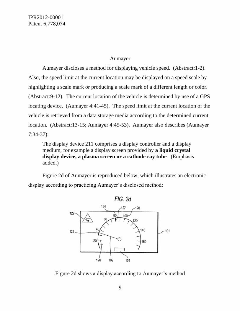
Aumayer discloses a method for displaying vehicle speed. (Abstract:1-2).
Also, the speed limit at the current location may be displayed on a speed scale by
highlighting a scale mark or producing a scale mark of a different length or color.
(Abstract:9-12). The current location of the vehicle is determined by use of a GPS
locating device. (Aumayer 4:41-45). The speed limit at the current location of the
vehicle is retrieved from a data storage media according to the determined current
location. (Abstract:13-15; Aumayer 4:45-53). Aumayer also describes (Aumayer
7:34-37):
The display device 211 comprises a display controller and a display
medium, for example a display screen provided by a liquid crystal
display device, a plasma screen or a cathode ray tube. (Emphasis
added.)
Figure 2d of Aumayer is reproduced below, which illustrates an electronic
display according to practicing Aumayer’s disclosed method:
Figure 2d shows a display according to Aumayer’s method

IPR2012-00001
Patent 6,778,074
10
With respect to Figure 2d, Aumayer describes that the determined speed
limit of 80 km/hr for the vehicle’s current location is shown by the speed scale
value 124 and speed scale mark 127 at the speed limit, both of which are
highlighted or emphasized such as by use of color different from that used for the
remainder of the display device, by enlargement, and/or by widening, on the
electronic display. (Aumayer 6:21-27). Aumayer expressly states that the speed
limit is highlighted or emphasized by the scale mark 127. (Aumayer 6:33-35).
Aumayer further states that “it is also possible to use a commercial
combined apparatus with mechanical display elements for the display device 211.”
(Aumayer 7:42-44). Specific details of that mechanical embodiment are not
described. However, Aumayer states that for example, “a speed limit can be made
visible by background lighting in a different color at the scale mark associated with
the corresponding speed limit.” (Aumayer 7:48-51).
Tegethoff
Tegethoff discloses an image display system for use on a vehicle, which
includes an image screen and an image generating computer. (Tegethoff 4:2:16-
18). The image displayed on the screen mimics that of analog mechanical pointer
instruments, and in their outer image form cannot be distinguished from purely
mechanical devices. (Tegethoff 4:2:34-40). Figure 2 of Tegethoff is reproduced
below, which illustrates an image of a speedometer and other useful information
(Tegethoff 5:2:30-32):

IPR2012-00001
Patent 6,778,074
11
Figure 2 shows an embodiment of Tegethoff’s image display
On the image shown above is displayed a mark 5 for indicating a currently
permissible maximum speed for the road section where the vehicle is currently
located. (Tegethoff 6:1:9-12). According to Tegethoff, that speed limit can be set
according to an element for navigation and a database. (Tegethoff 6:1:13-15).
Tegethoff describes that the critical markings such as that showing the speed limit
can be colored red. (Tegethoff 7:1:38-45).
Tokunaga
Tokunaga discloses a lighting unit capable of varying the luminescence and
color of illumination with respect to a target to be lit thereby to provide an
effective display of the target, and capable of itself serving as a display unit.
(Abstract 1-5). Tokunaga discloses two embodiments of the lighting unit, one
shown in Figure 1and one shown in Figure 3:

IPR2012-00001
Patent 6,778,074
12
Figures 1 and 3 illustrate separate embodiments of a lighting unit
In both embodiments, there is a light guide plate 1. In the Figure 1
embodiment, LEDs 2a-2d are directly fitted to the side edges of the light guide
plate, and in the Figure 3 embodiment, LEDs 2a-2d are indirectly provided to the
side edges of the light guide plate 1 through optical transmission media such as
optical fibers 5a-5d. (Tokunaga 2:12-22). The light guide plate 1 is suitable for
use as a backlight for a liquid crystal display panel on a portable electronic device.
(Tokunaga 2:37-41). Figure 2 shows the light guide plate 1 disposed next to a
liquid crystal display panel:
Figure 2 illustrates a partial sectional view of light guide plate 1

IPR2012-00001
Patent 6,778,074
13
Tokunaga describes that a liquid crystal display panel 3 is disposed on top of
the light guide plate 1 so as to permit the content of the liquid crystal display to be
irradiated with light sent from the light guide plate 1, and that under the light guide
plate 1 there is an electronic circuit board 4 for operating the liquid crystal display
panel. (Tokunaga 2:66 to 3:5). Tokunaga describes that the lighting unit can be
used to illuminate the liquid crystal display panel of a portable electronic game
machine such as GAME BOY®. (Tokunaga 3:54-59). Tokunaga also describes
that the liquid crystal display panel of the game machine is operated according to
image signals from an operation circuit and the light guide plate 1 is incorporated
into the game machine to illuminate the liquid crystal display. (Tokunaga 3:63-
68).
Tokunaga does not, however, describe specifically how the light guide
plate 1 is put in position relative to liquid crystal display panel 3 or electronic
circuit board 4. It is known only that the light guide plate 1 is incorporated into the
overall game machine, that the liquid crystal display is disposed on one side, and
that the electronic circuit board is disposed on the opposing side as shown in
Figure 2.
Tokunaga further states that although the description of the lighting unit
provided in the disclosure is made by way of example in the context of a game
machine, it would be obvious to those of ordinary skill in the art that the lighting
unit has other applications such as illuminating the display surfaces of a vehicle
speedometer. (Tokunaga 4:62-67). However, the statement of potential
application elsewhere is only general and Tokunaga does not describe any specific
structural implementation of the application of the lighting unit to a vehicle
speedometer. Tokunaga does state that in the case of application to a vehicle
speedometer, the color of the display light for the speedometer can be changed
IPR2012-00001
Patent 6,778,074
14
from blue to red if the vehicle speed exceeds a legal speed limit. (Tokunaga 5:1-
5). But it does not describe that the “legal speed limit” it refers to is one associated
specifically to the current location of the vehicle.
A. The alleged grounds based in whole or in part on Aumayer
Each of independent claims 1 and 10 requires that the speedometer be
“integrally attached” to the colored display. According to the petitioner, a single
liquid crystal display screen such as that of Aumayer’s display device 211, which
displays the image of both the speedometer and the colored scale mark 107
showing the speed limit, satisfies the claim requirement of an integral attachment
between a speedometer and a colored display. (Petition 18:1-4).
For reasons already discussed above, on this record we construe “integrally
attached” differently from the Petitioner. The single electronic display screen of
Aumayer showing both the image of a speedometer and a colored scale mark
indicating the current speed limit does not meet the claim recitation “integrally
attached” as applied to a speedometer and a colored display. There, the
speedometer and the colored display are not discrete and separately recognizable
parts that are “integrally attached” to each other. Rather, the liquid crystal display
screen is itself a single component which performs the function of both the
speedometer and colored display.
We recognized already that Aumayer states that “it is also possible to use a
commercial combined apparatus with mechanical display elements for the display
device 211.” (Aumayer 7:42-44). We also already recognized that Aumayer states
that “a speed limit can be made visible by background lighting in a different color
at the scale mark associated with the corresponding speed limit.” (Aumayer 7:48-
51). None of that disclosure indicates that a colored display is necessarily
integrally attached to the speedometer. No specific embodiment of a combined

IPR2012-00001
Patent 6,778,074
15
apparatus with mechanical display elements is described in sufficient detail. Even
Petitioner has not explained how such general disclosure meets the requirement of
“integrally attached” between the speedometer and the colored display.
A claim is anticipated only if each and every element as set forth in the
claim is found, either expressly or inherently, in a single prior art reference
Verdegaal Bros., Inc. v. Union Oil Co. of Cal., 814 F.2d 628, 631 (Fed. Cir. 1987).
Claims 2, 6-13, and 18-20 each depend directly or indirectly from either
claim 1 or claim 10. Because Aumayer fails to disclose the “integrally attached”
element of claims 1 and 10 as applied to the speedometer and the colored display,
there is not a reasonable likelihood that the Petitioner would prevail on its assertion
that claims 1, 2, 6-13, and 18-20 are anticipated by Aumayer under 35 U.S.C.
§ 102(e).
The above-noted deficiency of Aumayer with respect to independent claim 1
undermines Petitioner’s assertion of obviousness of claims 4 and 5 over Aumayer
and Evans under 35 U.S.C. § 103. Claim 4 depends on claim 1 and claim 5
depends on claim 4. Claims 4 and 5 recite the specific mechanical structure of a
speedometer, such as a needle, an axle, and a cable (claim 4), and a backplate and a
housing (claim 5). As applied by Petitioner to claims 4 and 5, Evans discloses all
of those elements but does not cure the above-noted deficiency of Aumayer
discussed in the context of independent claim 1 with regard to a colored display
being “integrally attached” to the speedometer. There is not a reasonable
likelihood that the petitioner would prevail on its assertion that claims 4 and 5
would have been obvious over Aumayer and Evans under 35 U.S.C. § 103.
Petitioner also asserts that claims 3 and 14-16 would have been obvious over
Aumayer and Evans, and that claim 17 would have been obvious over Aumayer,
Evans, and Wendt, under 35 U.S.C. § 103. As applied by Petitioner to claims 3

IPR2012-00001
Patent 6,778,074
16
and 14-16, Evans does seemingly disclose what Aumayer does not disclose, i.e., a
colored display which is “integrally attached” to the speedometer. However, the
above-noted deficiency of Aumayer is not cured by Petitioner’s reliance on Evans
because Petitioner has not articulated a credible rationale for combining the
teachings of Aumayer and Evans to arrive at the claimed invention.
Aumayer discloses an embodiment including each of the recited elements of
independent claims 1 and 10 of the ’074 Patent, except for the requirement that the
speedometer and the colored display are “integrally attached.” Claim 3 depends on
claim 1 and recites that the colored display is a colored filter. Claim 14 depends on
claim 10 and also recites that the colored display is a colored filter. Claim 15
depends on claim 14 and claim 16 depends on claim 15.
Evans discloses a combined vehicle speedometer and speed warning
indicator. (Evans 1:68 to 2:23). The speed warning indicator is installed on the
speedometer cover. (Evans 2:16-17). It comprises a transparent plate attached to
the transparent front cover of the speedometer. (Evans 2:1-3). Evans describes the
speed warning indicator as follows (Evans 2:3-8):
The plate bears warning indicia, for example, a special color and/or a
plurality of marks, spaces, ridges, etc. so that when the speedometer
dial is viewed through it, a portion of the dial representing speeds in
excess of a predetermined limit are demarked by the warning indicia.
(Emphasis added.)
Evans describes that a driver can tell what speeds are under or in excess of
the speed limit by making a swift reference to the speedometer through the
indicator and see whether the speedometer needle is in or out of the warning area
on the indicator plate. (Evans 2:9-13). Evans further describes that the indicator
plate can be made adjustable for changes in the speed limit. (Evans 2:18-19). As
shown in Figure 3, the red colored plate 12 is positioned on speed dial 30 so that

IPR2012-00001
Patent 6,778,074
17
only the portion of the dial which contains numbers representing speeds in excess
of the speed limit is overlaid by the plate:
Figure 3 illustrates a front elevation view of the
combined speedometer and speed warning indicator
The colored filter plate 12 of Evans is a fixed structure integrally attached to
the speedometer. However, although the plate may be removed and replaced, in its
operational state it is a fixed, non-moveable, and non-adjustable structure. In that
connection, Evans states (Evans 3:37-44):
It will be understood that plate 12 can, if desired, be removed from
cover 24 and either another similar plate of different configuration can
be substituted or plate 12 can be recut and repositioned or merely
repositioned on cover 24 so as to extend over another range of speed
numbers on dial 30. For example this would be desirable in the event
that the 55 mph current speed limit were abolished.
With regard to claims 3 and 14-16, Petitioner has not explained why one
with ordinary skill in the art would have chosen to use the fixed and immovable
colored plate 12 of Evans in combination with the dynamic display system of

IPR2012-00001
Patent 6,778,074
18
Aumayer which provides the benefits of a continuously controlled and updated
colored display to indicate the applicable speed limit for the vehicle at its current
location.
Accordingly, there is not a reasonable likelihood that the petitioner would
prevail on its assertion that claims 3 and 14-16 would have been obvious over
Aumayer and Evans under 35 U.S.C. § 103.
Claim 17 depends on claim 14, and states that the display controller rotates
the colored filter independently of the speedometer to continuously update the
delineation of which speed readings are in violation of the speed limit at a
vehicle’s present location. For claim 17, Petitioner relies on Wendt in combination
with Aumayer and Evans. Wendt and Evans in combination seemingly cures the
above-noted deficiency of Aumayer with regard to independent claim 10 and of
Aumayer and Evans with regard to claim 14. That is because Wendt teaches the
desirability of a rotatably moveable structure to indicate the speed limit.
The combined teachings of Aumayer, Evans, and Wendt appears to account
for all the features of claim 17. Accordingly, there is a reasonable likelihood that
the petitioner would prevail on its assertion that 17 would have been obvious over
Aumayer, Evans, and Wendt under 35 U.S.C. § 103.
Because claim 17 depends on claim 14 which depends on claim 10, and
because dependent claims include all of the features of the claims on which they
depend, Petitioner also has shown a reasonable likelihood that it would prevail on
demonstrating that claims 10 and 14 would have been obvious over the combined
teachings of Aumayer, Evans, and Wendt. We recognize that Petitioner did not
specifically articulate a ground of unpatentability against claims 10 and 14 based
on Aumayer, Evans, and Wendt. However, we exercise discretion to recognize

IPR2012-00001
Patent 6,778,074
19
that the assertion was implicitly made by Petitioner’s alleging that claim 17 would
have been obvious over Aumayer, Evans, and Wendt.
For claims 1-9, 11-13, 15, 16, and 18-20, we have not considered the ground
of obviousness under 35 U.S.C. § 103, based on the combined teachings of
Aumayer, Evans, and Wendt, and take no position in that regard. In this petition,
that ground of obviousness has not been asserted by Petitioner against those
claims, either expressly or by implication.
B. The alleged grounds based in whole or in part on Tegethoff
Each of independent claims 1 and 10 requires that the speedometer be
“integrally attached” to the colored display. Tegethoff shares the same deficiency
in that regard with Aumayer as discussed above. According to the Petitioner, a
single digital electronic display screen 37 that displays the image of both the
speedometer and the colored tick mark 5 showing the speed limit satisfies the
claim requirement of an integral attachment between a speedometer and a colored
display. (Petition 22:1-4).
For reasons already discussed above, on this record we construe “integrally
attached” differently from the Petitioner. The single digital electronic display
screen 37 of Tegethoff displaying both the image of a speedometer and a colored
tick mark 5 indicating the current speed limit does not meet the claim recitation
“integrally attached” as applied to a speedometer and a colored display. There, the
speedometer and the colored display are not discrete and separately recognizable
parts that are “integrally attached” to each other. Rather, the screen performs the
function of both the speedometer and colored display.
Claims 2, 6,and 7 each depend directly from claim 1. Because Tegethoff
fails to disclose the “integrally attached” element of claim 1 as applied to the
speedometer and the colored display, there is not a reasonable likelihood that the

IPR2012-00001
Patent 6,778,074
20
Petitioner would prevail on its assertion that claims 1, 2, 6, and 7 are anticipated by
Tegethoff under 35 U.S.C. § 102(b).
The above-noted deficiency of Tegethoff with respect to independent
claim 1 undermines Petitioner’s assertion of obviousness of claims 4 and 5 over
Tegethoff and Evans under 35 U.S.C. § 103. Claim 4 depends on claim 1 and
claim 5 depends on claim 4. Claims 4 and 5 recite the specific mechanical
structure of a speedometer, such as a needle, an axle, and a cable (claim 4), and a
backplate and a housing (claim 5). As applied by Petitioner to claims 4 and 5,
Evans discloses all of those elements but does not cure the above-noted deficiency
of Tegethoff discussed in the context of independent claim 1 with regard to a
colored display being “integrally attached” to the speedometer. There is not a
reasonable likelihood that Petitioner would prevail on its assertion that claims 4
and 5 would have been obvious over Tegethoff and Evans under 35 U.S.C. § 103.
Petitioner also asserts that claim 3 would have been obvious over Tegethoff
and Evans under 35 U.S.C. § 103. As applied by Petitioner to claim 3, Evans does
disclose what Aumayer does not disclose, i.e., a colored display which is
“integrally attached” to the speedometer. However, the above-noted deficiency of
Tegethoff is not cured by reliance on Evans because Petitioner has not articulated a
credible rationale for combining the teachings of Tegethoff and Evans to arrive at
the claimed invention. The deficiency is the same as that discussed above on the
lack of sufficient basis to combine the teachings of Evans and Aumayer. We note
again that the color filter of Evans is fixed and immoveable. Tegethoff requires a
colored display that is variable in position to reflect the current speed limit at the
current location of the vehicle. Accordingly, there is not a reasonable likelihood
that the Petitioner would prevail on its assertion that claim 3 would have been
obvious over Tegethoff and Evans under 35 U.S.C. § 103.
IPR2012-00001
Patent 6,778,074
21
As is the case with claim 1, with respect to claim 10 Tegethoff does not
disclose the limitation of a speedometer integrally attached to a colored display.
Petitioner’s reliance on Awada in combination with Tegethoff does not cure that
deficiency. Awada is relied on by the Petitioner in connection with claim 10 as
teaching the use of a global positioning system connected to a display controller
for providing signals for continuously updating the delineation of which speed
readings are in violation of the speed limit at the vehicle’s current location.
Claims 8, 9, and 20 each depend directly or indirectly on claim 1.
Claims 11-13, 18, and 19 each depend directly or indirectly on claim 10. Petitioner
relies on Awada in combination with Tegethoff as teaching the specific features
added by these dependent claims. However, as applied by the Petitioner, Awada
does not cure the deficiency of Tegethoff with respect to the limitation in
independent claims 1 and 10 that the speedometer is integrally attached to the
colored display. Thus, there is not a reasonable likelihood that the Petitioner
would prevail on its assertion that claims 8-13, and 18-20 would have been
obvious over Tegethoff and Awada under 35 U.S.C. § 103.
Claim 14 depends on claim 10 and recites that the colored display is a
colored filter. Claim 15 depends on claim 14 and claim 16 depends on claim 15.
For claims 14-16, Petitioner relies on Evans as teaching the use of a colored
filter that is attached to a speedometer. However, as is the case with Petitioner’s
attempted combination of Aumayer and Evans, already discussed above, Petitioner
has not articulated a credible rationale to make the purported combination of
Tegethoff and Evans. The colored filter of Evans is fixed and immoveable during
operation. Tegethoff, on the other hand, requires a colored display that can be
variably adjusted while the vehicle is in motion, to match the applicable speed
limit for the current location of the vehicle. Accordingly, there is not a reasonable

IPR2012-00001
Patent 6,778,074
22
likelihood that the Petitioner would prevail on its assertion that claims 14-16 would
have been obvious over Tegethoff, Awada, and Evans under 35 U.S.C. § 103.
Claim 17 depends on claim 14 and adds that the display controller rotates the
colored filter independently of the speedometer to continuously update the
delineation of which speed readings are in violation of the speed limit at the
vehicle’s present location. For claim 17, Petitioner relies on Wendt in combination
with Tegethoff, Awada, and Evans. Wendt and Evans together in combination
with Tegethoff and Awada seemingly cures the above-noted deficiency of
Tegethoff and Awada with regard to independent claim 10, and of Tegethoff,
Awada, and Evans with respect to claim 14. That is because Wendt teaches the
desirability of a rotatably moveable structure to indicate the speed limit.
The combined teachings of Tegethoff, Awada, Evans, and Wendt appears to
account for all of the features of claim 17. Accordingly, there is a reasonable
likelihood that Petitioner would prevail on its assertion that claim 17 would have
been obvious over Tegethoff, Awada, Evans, and Wendt under 35 U.S.C. § 103.
Because claim 17 depends on claim 14 which depends on claim 10, and
because dependent claims include all of the features of the claims on which they
depend, Petitioner also has shown a reasonable likelihood that it would prevail on
demonstrating that claims 10 and 14 would have been obvious over the combined
teachings of Tegethoff, Awada, Evans, and Wendt. We recognize that Petitioner
did not specifically articulate a ground of unpatentability against claims 10 and 14
based on Tegethoff, Awada, Evans, and Wendt. However, we exercise discretion
to recognize that the assertion was implicitly made by Petitioner’s alleging that
claim 17 would have been obvious over Tegethoff, Awada, Evans, and Wendt.
For claims 1-9, 11-13, 15, 16, and 18-20, we have not considered the ground
of obviousness under 35 U.S.C. § 103, based on the combined teachings of

IPR2012-00001
Patent 6,778,074
23
Tegethoff, Awada, Evans, and Wendt, and take no position in that regard. In this
petition, that ground of obviousness has not been asserted by Petitioner against
those claims, either expressly or by implication.
C. The alleged grounds based in whole or in part on Tokunaga
According to Petitioner, Tokunaga discloses each and every element of
independent claim 1. There are two problems with that assertion.
The first still relates to that same limitation which undermines the
anticipation assertion based on Aumayer and on Tegethoff, i.e., that the
speedometer is “integrally connected” to the colored display. Petitioner points out
that Tokunaga discloses that its lighting unit is incorporated into the game machine
so as to illuminate the liquid crystal display, and that in lieu of the gaming device
the lighting unit has other applications, for example, for providing illumination to
the surface of a vehicle speedometer. (Petition 23:16-21). On that basis alone,
Petitioner concludes that the “integrally connected” limitation is met. We disagree.
Tokunaga provides no specific description of how the lighting unit would be
attached to the display surface of a vehicle speedometer or if it is even attached.
And even in the context of a game machine, Tokunaga describes that liquid crystal
display panel 3 is disposed on top of the light guide plate 1 to permit the content of
the liquid crystal display to be irradiated with light sent from the light guide
plate 1, and that under the light guide plate 1 there is an electronic circuit board 4
for operating the liquid crystal display panel. (Tokunaga 2:66 to 3:5). That is not
a specific description of how the light guide plate 1 is put in position relative to
liquid crystal display panel 3. It is known only that light guide plate 1 is
incorporated into the overall game machine, that the liquid crystal display 3 is
disposed on one side of the light guide plate 1 and the electronic circuit board is
disposed on the opposing side as shown in Figure 2.

IPR2012-00001
Patent 6,778,074
24
Secondly, claim 1 requires a colored display to delineate which speed
readings are in violation of “the speed limit at a vehicle’s current location.”
Tokunaga does state that in the case of application to a vehicle speedometer, the
color of the display light for the speedometer can be changed from blue to red if
the vehicle speed exceeds a legal speed limit. (Tokunaga 5:1-5). But it does not
describe that the legal speed limit it refers to is associated specifically with the
current location of the vehicle. Petitioner has pointed to no description that the
referenced speed limit is location-based.
Accordingly, there is a not reasonable likelihood that Petitioner would
prevail on its assertion that claim 1 is anticipated by Tokunaga under 35 U.S.C.
§ 102(b).
As compared to claim 1, independent claim 10 adds the requirement of a
global positioning system receiver which outputs signals to the display controller
which adjusts the display to continuously update the delineation of which speed
readings are in violation of the speed limit at the vehicle’s current position. For
that limitation, Petitioner relies on the teachings of Hamamura, in combination
with that of Tokunaga. However, reliance on Hamamura does not cure the above-
noted deficiency of Tokunaga with regard to the “integrally attached” requirement
for the speedometer and the colored display.
Because it depends on claim 1, claim 20 also includes the requirement that
the speedometer is “integrally connected” to the colored display. As noted above,
however, with respect to that limitation, Petitioner’s reliance on Hamamura does
not cure the deficiency of Tokunaga.
In any event, Petitioner’s reliance on Hamamura to account for the limitation
of continuous updating the delineation of which speed readings are in violation of
the speed limit at the vehicle’s current location is misplaced because Petitioner’s

IPR2012-00001
Patent 6,778,074
25
analysis of Hamamura equates “safe speed” at a location with the speed limit at
that location. In the context of Hamamura, that is clearly not the case. Hamamura
discloses determining a safe speed for a vehicle location based on the speed limit
for that location, road shape “and the like” of each road. (Hamamura 3:[0008]).
Hamamura discloses displaying the “safe speed” at the vehicle’s current location
(Hamamura 1:[Constitution]:3-4) and states that the legal speed limit of a road on
which the vehicle is currently running may not agree with a speed at which the
vehicle can actually run safely. (Hamamura 3:[0004]:12-14).
There is a not reasonable likelihood that Petitioner would prevail on its
assertion that claims 10 and 20 would have been obvious over Tokunaga and
Hamamura under 35 U.S.C. § 103.
CONCLUSION
Petitioner has demonstrated a reasonable likelihood of prevailing on its
challenge of claims 10, 14, and 17 of the ’074 Patent as obvious under 35 U.S.C.
§ 103 (1) over Aumayer, Evans, and Wendt, and (2) over Tegethoff, Awada,
Evans, and Wendt.
Petitioner has not demonstrated a reasonable likelihood of prevailing on its
challenge of any other claim on any ground.
Order
It is
ORDERED that the Petition is denied as to claims 1, 2, 6, 7, 8, 9, 10, 11,
12, 13, and 18-20 of the ʼ074 patent on the alleged ground of anticipation by
Aumayer under 35 U.S.C. § 102(e);
FURTHER ORDERED that the Petition is denied as to claims 1, 2, 6, and
7 of the ‘074 patent on the alleged ground of anticipation by Tegethoff under
35 U.S.C. § 102(b);

IPR2012-00001
Patent 6,778,074
26
FURTHER ORDERED that the Petition is denied as to claim 1 of the
‘074 patent on the alleged ground of anticipation by Tokunaga under 35 U.S.C.
§ 102(b);
FURTHER ORDERED that the Petition is denied as to claims 3-5 and 14-
16 of the ‘074 patent on the alleged ground of obviousness over Aumayer and
Evans under 35 U.S.C. § 103;
FURTHER ORDERED that the Petition is granted as to claims 10, 14, and
17 of the ‘074 patent on the alleged ground of obviousness over Aumayer, Evans,
and Wendt under 35 U.S.C. § 103;
FURTHER ORDERED that the Petition is denied as to claims 3-5 on the
alleged ground of obviousness over Tegethoff and Evans under 35 U.S.C. § 103;
FURTHER ORDERED that the Petition is denied as to claims 8-13 and
18-20 on the alleged ground of obviousness over Tegethoff and Awada under
35 U.S.C. § 103;
FURTHER ORDERED that the Petition is denied as to claims 14, 15, and
16 on the alleged ground of obviousness over Tegethoff, Awada, and Evans under
35 U.S.C. § 103;
FURTHER ORDERED that the Petition is granted as to claims 10, 14, and
17 on the alleged basis of obviousness over Tegethoff, Awada, Evans, and Wendt
under 35 U.S.C. § 103;
FURTHER ORDERED that the Petition is denied as to claims 10 and 20
on the alleged ground of obviousness over Tokunaga and Hamamura under
35 U.S.C. § 103;
FURTHER ORDERED that pursuant to 35 U.S.C. § 314(a), a trial for inter
partes review of the ʼ074 patent is hereby instituted, commencing on the entry date

IPR2012-00001
Patent 6,778,074
27
of this Order, and pursuant to 35 U.S.C. § 314(c) and 37 C.F.R. § 42.4, notice is
hereby given of the institution of trial;
FURTHER ORDERED that the trial is limited to the two above-stated
grounds of obviousness directed to claims 10, 14, and 17, and that no other ground
for any claim is authorized for trial; and
FURTHER ORDERED that an initial conference call with the Board is
scheduled for 1 PM EST on January 23, 2013; the parties are directed to the
Office Trial Practice Guide, 77 Fed. Reg. 48756, 48765-66 (Aug. 14, 2012) for
guidance in preparing for the initial conference call, and should come prepared to
discuss any proposed changes to the Scheduling Order entered herewith and any
motions the parties anticipate filing during the trial.

IPR2012-00001
Patent 6,778,074
28
For PETITIONER:
Jennifer C. Bailey
HOVEY WILLIAMS LLP
For PATENT OWNER
John R. Kasha
Kasha Law LLC
Cabrach J. Connor
Reed & Scardino LLP