[email protected] paper 34 tel: 571-272-7822 entered:...
TRANSCRIPT

[email protected] Paper 34 Tel: 571-272-7822 Entered: April 21, 2015
UNITED STATES PATENT AND TRADEMARK OFFICE _______________
BEFORE THE PATENT TRIAL AND APPEAL BOARD _______________
MEDTRONIC, INC. AND MEDTRONIC VASCULAR, INC., Petitioners,
v.
LIFEPORT SCIENCES LLC, Patent Owner.
_______________
Case IPR2014-00288 Patent 7,147,662
_______________
Before LORA M. GREEN, SCOTT E. KAMHOLZ, and ROBERT A. POLLOCK, Administrative Patent Judges. POLLOCK, Administrative Patent Judge.
FINAL WRITTEN DECISION 35 U.S.C. § 318(a) and 37 C.F.R. § 42.73

IPR2014-00288 Patent 7,147,662
2
I. INTRODUCTION
A. Procedural Posture
Petitioners, Medtronic, Inc. and Medtronic Vascular, Inc.
(collectively, “Petitioners”), filed a corrected Petition (Paper 6, “Pet.”)
requesting inter partes review of claims 1–16 of U.S. Patent No. 7,147,662
(Ex. 1001, “the ’662 patent”) on multiple grounds. Patent Owner, Lifeport
Sciences LLC (“Lifeport”), did not file a preliminary response.
The Board instituted trial for claims 1–5, 7–13, 15, and 16 on certain
grounds raised by Petitioners. Decision to Institute 37–38 (Paper 8, “Dec.”).
After institution of trial, Lifeport filed a Patent Owner Response (Paper 13,
“Resp.”), and Petitioners filed a corresponding Reply (Paper 14, “Reply”).
Lifeport did not file a Motion to Amend.
Petitioners rely upon the Declaration (Ex. 1026), supplemental
Declaration (Ex. 1034), and deposition testimony of Dr. Gary L. Loomis
(Ex. 1035). Lifeport relies on the Declaration of Ellen Golds (Ex. 2001) and
excerpts from Dr. Loomis’s deposition (Paper 21). Petitioners filed a
Motion to Exclude portions of Dr. Loomis’s testimony (Paper 22 (“Motion
to Exclude Evidence”). Lifeport opposes Petitioners’ Motion to Exclude
Evidence (Paper 23), and Petitioners filed a Response to Lifeport’s
Opposition (Paper 24).
The Board heard oral argument on February 18, 2015. A transcript is
entered as Paper 32 (“Tr.”).
The Board has jurisdiction under 35 U.S.C. § 6(c). This final written
decision is issued pursuant to 35 U.S.C. § 318(a) and 37 C.F.R. § 42.73.

IPR2014-00288 Patent 7,147,662
3
Upon consideration of the arguments and evidence of record, we
determine that Petitioners have not proven by a preponderance of the
evidence that claims 1–5, 7–13, 15, and 16 are unpatentable.
Petitioners’ Motion to Exclude Evidence is dismissed as moot.
B. The ’662 Patent
The ’662 patent relates to a hook for attaching an endoluminal
prosthesis, such as a graft or stent, within an artery, vein, or other type of
corporeal lumen. Ex. 1001, 1:14–22. The hook is configured for
intraluminal delivery and deployment. Id. at Abstract. “The hook is
integrally formed with [a] framing structure and is preset into an outward
bend, but is resiliently flexible so as to form a substantially straight profile
when compressed.” Id.
Figure 1 of the ’662 patent is set forth below:
Figure 1 is a perspective view of one embodiment of the disclosed hook and
frame combination, showing a hook 20 formed integrally within a frame 22.
Id. at 2:45–46, 3:11–12. Hook 20 consists of elongated member 24 having a
pointed end 26. Id. at 3:13–14. Hook 20 “may be bent or curved such that
the pointed end 26 extends out of the frame 22.” Id. at 3:14–15. Hook 20
may be formed in frame 22 by cutting incisions 40 into frame 22, leaving
IPR2014-00288 Patent 7,147,662
4
hook 20 bounded on three sides by incisions 40 and forming elongated
member 24 and pointed end 26. Id. at 4:55–62.
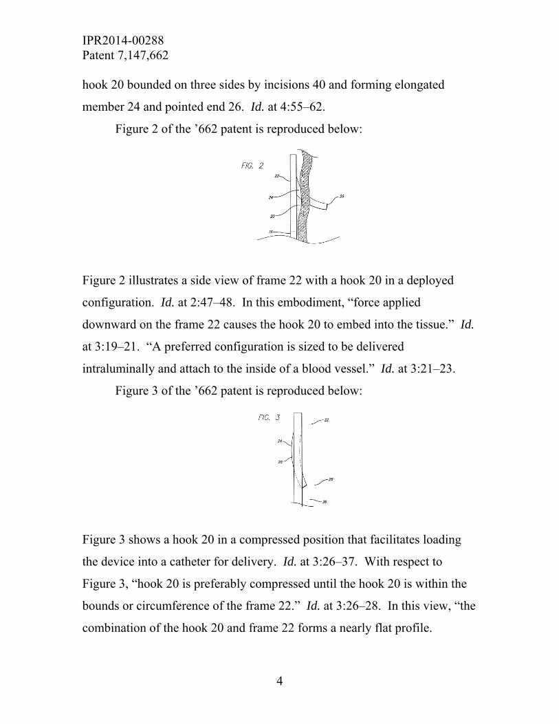
Figure 2 of the ’662 patent is reproduced below:
Figure 2 illustrates a side view of frame 22 with a hook 20 in a deployed
configuration. Id. at 2:47–48. In this embodiment, “force applied
downward on the frame 22 causes the hook 20 to embed into the tissue.” Id.
at 3:19–21. “A preferred configuration is sized to be delivered
intraluminally and attach to the inside of a blood vessel.” Id. at 3:21–23.
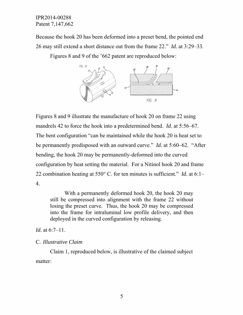
Figure 3 of the ’662 patent is reproduced below:
Figure 3 shows a hook 20 in a compressed position that facilitates loading
the device into a catheter for delivery. Id. at 3:26–37. With respect to
Figure 3, “hook 20 is preferably compressed until the hook 20 is within the
bounds or circumference of the frame 22.” Id. at 3:26–28. In this view, “the
combination of the hook 20 and frame 22 forms a nearly flat profile.
IPR2014-00288 Patent 7,147,662
5
Because the hook 20 has been deformed into a preset bend, the pointed end
26 may still extend a short distance out from the frame 22.” Id. at 3:29–33.
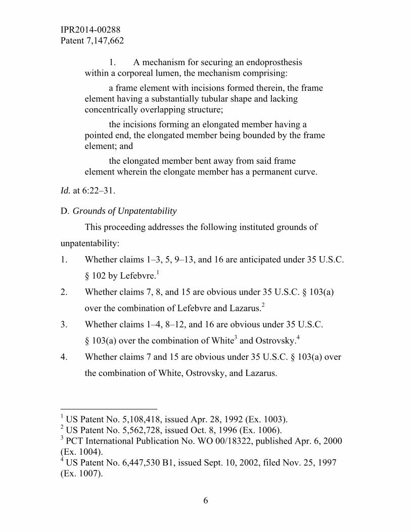
Figures 8 and 9 of the ’662 patent are reproduced below:
Figures 8 and 9 illustrate the manufacture of hook 20 on frame 22 using
mandrels 42 to force the hook into a predetermined bend. Id. at 5:56–67.
The bent configuration “can be maintained while the hook 20 is heat set to
be permanently predisposed with an outward curve.” Id. at 5:60–62. “After
bending, the hook 20 may be permanently-deformed into the curved
configuration by heat setting the material. For a Nitinol hook 20 and frame
22 combination heating at 550° C. for ten minutes is sufficient.” Id. at 6:1–
4.
With a permanently deformed hook 20, the hook 20 may still be compressed into alignment with the frame 22 without losing the preset curve. Thus, the hook 20 may be compressed into the frame for intraluminal low profile delivery, and then deployed in the curved configuration by releasing.
Id. at 6:7–11.
C. Illustrative Claim
Claim 1, reproduced below, is illustrative of the claimed subject
matter:
IPR2014-00288 Patent 7,147,662
6
1. A mechanism for securing an endoprosthesis within a corporeal lumen, the mechanism comprising:
a frame element with incisions formed therein, the frame element having a substantially tubular shape and lacking concentrically overlapping structure;
the incisions forming an elongated member having a pointed end, the elongated member being bounded by the frame element; and
the elongated member bent away from said frame element wherein the elongate member has a permanent curve.
Id. at 6:22–31.
D. Grounds of Unpatentability
This proceeding addresses the following instituted grounds of
unpatentability:
1. Whether claims 1–3, 5, 9–13, and 16 are anticipated under 35 U.S.C.
§ 102 by Lefebvre.1
2. Whether claims 7, 8, and 15 are obvious under 35 U.S.C. § 103(a)
over the combination of Lefebvre and Lazarus.2
3. Whether claims 1–4, 8–12, and 16 are obvious under 35 U.S.C.
§ 103(a) over the combination of White3 and Ostrovsky.4
4. Whether claims 7 and 15 are obvious under 35 U.S.C. § 103(a) over
the combination of White, Ostrovsky, and Lazarus.
1 US Patent No. 5,108,418, issued Apr. 28, 1992 (Ex. 1003). 2 US Patent No. 5,562,728, issued Oct. 8, 1996 (Ex. 1006). 3 PCT International Publication No. WO 00/18322, published Apr. 6, 2000 (Ex. 1004). 4 US Patent No. 6,447,530 B1, issued Sept. 10, 2002, filed Nov. 25, 1997 (Ex. 1007).

IPR2014-00288 Patent 7,147,662
7
II. ANALYSIS
A. Claim Construction
In an inter partes review, claim terms in an unexpired patent are
interpreted according to their broadest reasonable construction in light of the
specification of the patent in which they appear. 37 C.F.R. § 42.100(b); see
In re Cuozzo Speed Techs., LLC, 778 F.3d 1271, 1278–82 (Fed. Cir. Feb. 4,
2015). Under this standard, claim terms are given their ordinary and
customary meaning, as would be understood by one of ordinary skill in the
art in the context of the entire disclosure. In re Translogic Tech., Inc., 504
F.3d 1249, 1257 (Fed. Cir. 2007). “Because claim terms are normally used
consistently throughout the patent, the usage of a term in one claim can often
illuminate the meaning of the same term in other claims. Differences among
claims can also be a useful guide in understanding the meaning of particular
claim terms.” Phillips v. AWH Corp., 415 F.3d 1303, 1314 (Fed. Cir. 2005)
(citations omitted).
For the purpose of this decision, we focus on the construction of the
term “permanent curve.” The ’662 patent does not provide an express
definition of this term. Nor does the patent use the precise term “permanent
curve” other than in the claims. During examination of the application upon
which the ’662 patent issued, however, the Examiner articulated the broadest
reasonable construction, in light of the Specification, of “permanent curve”
as “a preset curve that . . . maintains a permanent curve regardless of what
configuration the device is in.” See Ex. 1002, 145 (Examiner’s Reasons for
Allowance). Based on that construction, the Examiner allowed the claims.
See id. at 144–45.

IPR2014-00288 Patent 7,147,662
8
Citing the testimony of its expert, Gary L. Loomis, Ph.D., Petitioners
urged us to adopt the same construction applied by the Examiner. Pet. 9
(citing Ex. 1026 ¶ 60). Dr. Loomis testified that the proffered construction
“is supported by the specification and file history and is consistent with that
which was applied by the Examiner in his Reasons for Allowance.” Ex.
1026 ¶ 60.
For the purposes of instituting inter partes review, we agreed with
Petitioners and Petitioners’ expert that the broadest reasonable interpretation
consistent with the Specification of a “permanent curve” is “a preset curve
that maintains a permanent curve regardless of what configuration the device
is in.” Dec. 9 (citing Ex. 1001, 6:1–11). Lifeport and Lifeport’s expert,
Ellen Golds, also agreed with that construction. Resp. 7; Ex. 2001 ¶ 27.
The parties disagree, however, as to whether, under that construction, a
permanent curve encompasses a resilient, flexible member that maintains
some degree of curvature—even though the arc of the curve may change due
to compressive forces—or whether it more narrowly demands a fixed arc
that does not vary during use. See, e.g., Reply 7; Tr. 7:24–8:5, 8:16–25,
23:17–24:3.
Petitioners consider the claims unpatentable according to both
interpretations. Tr. 9:1–14. With respect to the broader interpretation,
Petitioners’ expert states that the engagement members of Figure 6b of the
White reference, “when made of a resilient spring-aided change material
such as nitinol, would maintain a permanent curve in both their compressed
and expanded positions . . . such spring aided materials, if curved in their
uncompressed orientation, would maintain a curve when compressed.” Ex.
1026 ¶ 101; see also Pet. 38 (citing Ex. 1026 ¶ 177 (“it is an inherent
IPR2014-00288 Patent 7,147,662
9
property of the heat aided and spring-aided change materials described in
White that the curve would be permanent”).
Lifeport argues that “Dr. Loomis appears to erroneously conflate
materials having shape ‘memory’ with materials having a permanent curve.”
Resp. 37; see Ex. 2001 ¶ 86. In Lifeport’s view, although “a material has
‘memory’ in that it changes shape when compressed and then returns to its
prior shape when not compressed,” that is quite different from a “permanent
curve,” which is “a preset curve that maintains a permanent curve regardless
of what configuration the device is in.” Resp. 37 (citing Ex. 2001 ¶ 86).
Lifeport’s expert further emphasizes that engagement members that
resiliently return to a memorized shape embody the opposite of a permanent
curve. Ex. 2001 ¶ 84.
As summarized by Petitioners, Lifeport’s broadest reasonable
interpretation of permanent curve thus requires that
the curve of the elongated member/hook/ protrusion must be identical in all configurations of the device, and at all times. Any temporary change to the curvature would mean that it is not permanent, and would fall outside of the scope of the claims. That would exclude a curve that is deformed into a flattened or different curvature during deployment, and that elastically returns to a memorized curvature.
Reply 7 n.5 (internal citations and parenthetical omitted). That definition is
consistent with the ordinary meaning of “permanent” as “lasting or
continuing for a very long time or forever: not temporary or changing.”5 See
Vitronics Corp. v. Conceptronic, Inc., 90 F.3d 1576, 1584 n.6 (Fed. Cir.
5 MERRIAM-WEBSTER, http://www.merriam-webster.com/dictionary/permanent (last accessed Feb. 24, 2015).

IPR2014-00288 Patent 7,147,662
10
1996) (“[We] may also rely on dictionary definitions when construing claim
terms, so long as the dictionary definition does not contradict any definition
found in or ascertained by a reading of the patent documents.”)
The Specification of the ’662 patent references a hook or protrusion as
having a “bend” and a “curve.” For example, the Specification teaches that
in manufacturing an embodiment of the present invention, “hook 20” may be
forced into “a predetermined bend” (Ex. 1001, 5:55–67) and then
“permanently-deformed into the curved configuration by heat setting the
material” (id. at 6:1–3). Independent claims 10 and 16, however, make clear
that the terms “bend” and “curve” are not necessarily coextensive. In
relevant part, these claims recite (emphasis added):
10. . . . a hook having two sides and a point . . . said hook having a permanent bend that forms a permanent curve.
16. . . . at least one protrusion . . . having a resiliently flexible bend formed therein, wherein the at least one protrusion has a permanent curve . . . and the at least one protrusion having a pointed end.
In each case, the claims require a hook or protrusion having both a
permanent curve and either a permanent bend (claim 10), or a resiliently
flexible bend (claim 16). Thus, with respect to the claimed bend, “resiliently
flexible” is an express alternative to “permanent.”
Considering the teachings of the Specification, we conclude that the
curve element must be permanent, as recited in the claims, rather than
“resiliently flexible.” The Specification teaches that in some embodiments,
the hook or protrusion “is resiliently flexible so as to form a substantially
straight profile when compressed,” (Ex. 1001, Abstract) but “may be
IPR2014-00288 Patent 7,147,662
11
permanently-deformed into the curved configuration by heat setting the
material” (id. at 6:1–4). As emphasized by Lifeport, the Specification
teaches that a permanently deformed hook and frame—and, thus, a
permanent curve—can be produced by heating Nitinol hook and frame
combinations “at 550° for ten minutes.” Resp. 25–26 (citing Ex. 1001, 6:3–
4); see Ex. 2001 ¶ 77. When thus “permanently deformed,” “hook 20 may
still be compressed into alignment with the frame 22 without losing the
preset curve,” and subsequently “deployed in the curved configuration by
releasing.” Ex. 1001, 6:7–9 (emphases added).
We further note that the Specification makes clear that the disclosed
hooks are incorporated into a variety of devices deployed in the veins of
living bodies (see, e.g., Ex. 1001, 3:60–4:8), and subject to various physical
forces therein. The ’662 patent, thus, discloses an embodiment having “a
plurality of hooks 20 from the same incisions 40,” which “could form hooks
20 which project in opposing directions” and “provide superior resistance to
radial and axial loads from the corporeal lumen and blood flow.” Ex. 1001,
5:33–37.
In light of the foregoing, we refine our construction of “permanent
curve” to be “a preset curve that maintains a fixed arc throughout normal use
regardless of what configuration the device is in.” Insofar as Petitioners,
and/or Petitioners’ expert, argue that the challenged claims are unpatentable
under multiple constructions of this term, we address only those arguments
relevant to this construction below.
IPR2014-00288 Patent 7,147,662
12
B. Patentability Analysis
To prevail in its challenges to claims 1–5, 7–13, 15, and 16,
Petitioners must prove unpatentability by a preponderance of the evidence.
See 35 U.S.C. § 316(e); 37 C.F.R. § 42.1(d).
In finding a claim anticipated, “[t]he identical invention must be
shown in as complete detail as is contained in the . . . claim.” Richardson v.
Suzuki Motor Co., 868 F.2d 1226, 1236 (Fed. Cir. 1989). Moreover, “[a]
claim is anticipated only if each and every element as set forth in the claim is
found, either expressly or inherently described, in a single prior art
reference.” Verdegaal Bros. v. Union Oil Co. of Cal., 814 F.2d 628, 631
(Fed. Cir. 1987). A finding of inherency “requires that the missing
descriptive material is ‘necessarily present,’ not merely probably or possibly
present” in the anticipating reference. Trindec Indus., Inc. v. Top-USA
Corp., 295 F.3d 1292, 1295 (Fed. Cir. 2002) (quoting In re Robertson, 169
F.3d 743, 745 (Fed. Cir. 1999)).
A claim is unpatentable under 35 U.S.C. § 103(a) if the differences
between the subject matter sought to be patented and the prior art are such
that the subject matter as a whole would have been obvious at the time the
invention was made to a person having ordinary skill in the art to which the
subject matter pertains. KSR Int’l Co. v. Teleflex Inc., 550 U.S. 398, 406
(2007).
a. Anticipation of Claims 1–3, 5, 9–13, and 16 by Lefebvre
Petitioners contend that claims 1–3, 5, 9–13, and 16 are unpatentable
as anticipated by Lefebvre. Pet. 11–18. For the reasons set forth below, we

IPR2014-00288 Patent 7,147,662
13
find that Petitioners have failed to establish that Lefebvre discloses the
permanent curve recited in each independent claim at issue.
i. Overview of Lafebvre
Lefebvre describes an implantable filter for retaining blood clots in a
vein. See Ex. 1003, Abstract, 1:7–11. Lefebvre Figure 1 is reproduced
below:
Lefebvre Figure 1 illustrates a side view of filter 1 “placed inside a vein 2 in
which blood flows in the direction of arrow F.” Id. at 2:46, 2:52–54. Filter
1 “is generally conical in shape, with lateral legs 3” joined to form head 4 of
the filter. Id. at 2:55–57. Lefebvre explains that the filter is made “of a
material which presents a certain elasticity, with the result that the legs 3
may be brought substantially against one another in a sheath for
introduction, of the catheter . . . and [legs 3] open out inside the vein 2 when
the filter is pushed out of the sheath.” Id. at 2:60–65.
As shown in Figure 1, free end 5 of each leg 3 includes two teeth 6, 7.
Id. at 2:57–59. In a preferred embodiment, the teeth have the form “of two
triangles of which the parallel bases, fast with the leg, are spaced apart by a
distance of between 2 and 10 mm.” Id. at 2:33–36. The “two teeth . . . are

IPR2014-00288 Patent 7,147,662
14
inclined with respect to the surface of the leg, one in the direction of flow of
the blood and the other in the opposite direction.” Id. at 1:64–66. Lefebvre
Figure 2, reproduced below, illustrates the manufacture of teeth 6 and 7 from
a lateral leg:
Lefebvre Figure 2 illustrates a view of the end of a lateral leg of a filter. Id.
at 2:46. “To produce teeth 6, 7 two cut-outs are made along solid lines 10,
11.” Id. at 3:5–9. Tooth 7, for example, is formed by “pushing the
triangular part defined by cuts 12, 13, outwardly of leg 3.” Id. at 3:10–13.
The legs of the device, and thus the resulting teeth, can be made from a
resilient metal. See Ex. 1026 ¶ 70 (citing Ex. 1003, 2:59–68). Lefebvre
further discloses that “it is advantageous if the tooth is curved or bent” (Ex.
1003, 2:25–26), such as “by curving the tooth along an arc of circle” (id. at
4:16–18). In a deployed configuration, the teeth penetrate the wall of the
vessel to hook the filter “without any possibility of subsequent migration.”
Id. at 4:1–4; see id. at 2:46–56.

IPR2014-00288 Patent 7,147,662
15
Lefebvre Figure 3 is reproduced below:
Lefebvre Figure 3 shows a longitudinal section of the end of a leg 3
positioned against the inner surface 23 of a vein, with teeth 6, 7 penetrating
into vein wall 8. Id. at 2:47–48; 3:45–48; 4:1–3. Teeth 6, 7 are each bent
along an axis of bend 20, which separates the triangular end 25 of the tooth
from the trapezoidal base portion 22 having base 19 where the tooth joins
leg 3. Id. at 3:27–33. Lefebvre Figure 3 shows that two angular
measurements, α and β, converge at bend 20. “The angle α [is] formed
between the triangular end part 21 of the tooth and the direction D’ of the
plane of the leg 3,” and “[t]he angle β [is] formed between the trapezoidal
part 22 of the tooth and the direction D’ of the plane of the leg 3.” Id. at
3:34–41.
ii. Analysis
Petitioners contend that Lefebvre’s device has a permanent curve
under Lifeport’s construction of the term which, as explained above, is
reasonably consistent with our construction (i.e., a preset curve that
maintains a fixed arc throughout normal use regardless of what
configuration the device is in). See Reply 7. In particular, Petitioners rely
on Dr. Loomis in asserting that “the geometry disclosed in Lefebvre allows a

IPR2014-00288 Patent 7,147,662
16
tooth made of elastic material to maintain the same curvature at bend 20
despite conformational changes,” and “[a]s the device is inserted into the
catheter bend 20 remains unchanged when the tooth is compressed within
the frame.” Id. (citing Ex. 1034 ¶¶ 5–9.)
Dr. Loomis models the geometry of tooth 6 in Lefebvre Figure 6
when a catheter sheath or “other force” 6 compresses the Lefebvre device.
Ex. 1034 ¶¶ 5–9. Dr. Loomis’s first illustration of a modified version of
Lefebvre Figure 6 is reproduced below.
According to Dr. Loomis, this figure shows:
When the catheter sheath or other force compresses the device, the geometry of the tooth directs the point of contact to bend 20, where the compression force will act. The compression force is transferred along trapezoidal part 22, which acts as a lever arm with a fulcrum where trapezoidal part 22 contacts the base 19.
Ex.1034 ¶ 6.
Dr. Loomis’s second and third illustrations are adapted from Lefebvre
Figure 6 and are reproduced below.
6 Although Dr. Loomis indicates that some “other force” may compresses the Lefebvre device (Ex. 1034 ¶ 6), the only force addressed in his opinion comes from the application of a catheter sheath.

IPR2014-00288 Patent 7,147,662
17
According to the adapted illustrations, as the catheter sheath advances from
left to right, tooth 6 compresses but bend 20 remains unchanged.7 See id.
¶¶ 7–8. In this model, “the point of contact remains at bend 20, there is no
force acting on any portion of end part 21.” Id. ¶ 8. “Accordingly,” Dr.
Loomis explains, “there is no force that will change the angle made at bend
20, which remains constant through the conformational change. In this way,
bend 20 is a permanent curve as claimed in the ’662 patent.”8 Id. In sum,
Dr. Loomis testifies that as the catheter sheath covers the Lefebvre device,
“there will be portions of the curve formed in place of bend 20 that do not
experience any force from the catheter. Those portions will remain
unchanged and maintain the same curve in either the compressed or
expanded configurations.” Id. ¶ 10.
7 Dr. Loomis testified that he could have just as easily based his analysis on tooth 7, in which case the catheter sheath would be shown as moving from right to left. Tr. 57:1–10. 8 Dr. Loomis further states that the ’662 patent similarly discloses “elastic deformation at the base of the tooth . . . where the base of the engagement member acts as a fulcrum to allow the engagement member to be compressed within the frame.” Id. ¶ 9 (referencing Ex. 1001, Figs. 2 and 3, 3:26–28).
IPR2014-00288 Patent 7,147,662
18
Lifeport asserts that Petitioners fail to establish by a preponderance of
evidence that Lefebvre teaches a permanent curve. Resp. 22–26. Lifeport’s
expert argues that nothing in Lefebvre indicates that the teeth have a
permanent curve. Id. (citing Ex. 2001 ¶¶ 75–78); see Ex. 2001 ¶47. To the
contrary, because the teeth are cut from leg 3, which is expressly described
as elastic, a person of ordinary skill in the art would conclude that teeth do
not have a permanent curve. See id. ¶ 47.
Lifeport has the more persuasive position. First, we note that
endoprostheses such as those disclosed in the ’662 patent are deployed and
function in a living body (see, e.g., Ex. 1001, 3:60–4:8). Accordingly, our
construction of permanent curve as a preset curve that maintains a fixed arc
throughout normal use regardless of the configuration of the device, is not
limited to sheathed and unsheathed configurations taken in isolation.
Thus, whereas Dr. Loomis’s analysis of Lefebvre focuses on the force
applied by a catheter sheath impinging on a single tooth of the Lefebvre
device, “throughout normal use” more broadly encompasses the deployed
configuration of Lefebvre Figure 3 in which teeth 6, 7 penetrate into the vein
wall “one in the direction of flow of the blood and the other in the opposite
direction.” See Ex. 1003, 1:64–66. Dr. Loomis addressed the compressive
effects during the application of a catheter sheath. We find no evidence that
Dr. Loomis addressed compressive, hemodynamic, or other forces on the
Lefebvre teeth when the device is deployed and functioning in normal use.9
9 Although an analysis of the forces applied to the Lefebvre device when it is deployed in a vein is among the issues raised in Medtronic’s Motion to Exclude Evidence, we need not resort to Dr. Loomis’s contested testimony as the omission is self-evident. We also are not persuaded by Medtronic’s assertion that Figure 3 and column 3, lines 34–42, of Lefebvre demonstrate

IPR2014-00288 Patent 7,147,662
19
The evidence of record is, therefore, insufficient to demonstrate that
Lefebvre maintains a permanent curve as properly construed.
Second, with respect to the configurations of Lefebvre that Dr.
Loomis does address, we find his analysis speculative and accord it little
weight. It is within our discretion to assign the appropriate weight to be
accorded to evidence. See Ashland Oil, Inc. v. Delta Resins & Refractories,
Inc., 776 F.2d 281, 294 (Fed. Cir. 1985) (under the Federal Rules of
Evidence, which are applicable here,10 “[o]pinion testimony rendered by
experts must be given consideration, and while not controlling, generally is
entitled to some weight. Lack of factual support for expert opinion going to
factual determinations, however, may render the testimony of little probative
value in a validity determination.”) (citations omitted); see also In re Am.
Acad. of Sci. Tech Ctr., 367 F.3d 1359, 1368 (Fed. Cir. 2004) (“[T]he Board
is entitled to weigh the declarations . . . and conclude that the lack of factual
corroboration warrants discounting the opinions expressed in the
declarations.”).
In weighing Petitioners’ expert testimony, we take into account the
lack of evidence that Dr. Loomis (1) considered the physical dimensions of
the Lefebvre components, such as the distance between teeth, and the
that the angles of teeth 6, 7 do not change when impaled in the vein. Tr. 12:1–13:18. The specifically recited angles for α (15°) and β (60°) of Lefebvre Figure 3 (“the example” of the referenced passage) refer to the device as shown deployed in the vein. On the record before us, we agree with Lifeport that the cited passage is “not saying that it maintains that shape in all configurations of the device.” Id. at 25:10–17. 10 See 37 C.F.R. § 42.62 (“the Federal Rules of Evidence shall apply to” an inter partes review, except for exclusions not applicable here).
IPR2014-00288 Patent 7,147,662
20
clearance between a catheter sheath and elements of the Lefebvre device—
including the second, opposing tooth11 (see Ex. 1035, 21:7–15, 29:2–10; Tr.
48:19–20:4); (2) took into account material properties of the metal used to
form the Lefebvre legs and teeth, such as the modulus of elasticity12 (Ex.
1035, 15:9–24 (Lefebvre “[d]oes not disclose a specific elastic modulus of
the metal used.”); see also id. at 27:14–21 (“For the sake of my analysis, I
didn’t make any assumptions as to whether [the tooth and leg] were the same
material or . . . different materials.”)); or (3) employed any computer
modeling, physical models, or mockup of any embodiment disclosed in
Lefebvre (id. at 16:24–17–6; 17:7–18:6; see Tr. 13:19–14:2). Those factors
point to a lack of rigor and reliability in Dr. Loomis’s analysis.
Our concerns are heightened by Dr. Loomis’s apparent lack of
expertise in the relevant field. Although Dr. Loomis testified that he took
“seminars on mechanical behaviors of metals as used in the biomedical
device industry” (id. at 10:1–6), and as “the director [of] mechanical analysis
of materials used in medical devices” (id. at 10:19–20), oversaw the
“stress/strain analysis testing, radio compression analysis done on
11 At best, Dr. Loomis testified that the opposing teeth “would have to be compressed or else they would embed in the catheter,” but provided no indication how that would be accomplished according to his model. See Tr. 57:11–58:3. 12 According to Dr. Loomis, modulus of elasticity is “a way of describing the force required to stretch a material. The higher the modulus, the more force is required to stretch [or deform] the material.” Ex. 1035, 12:18–25; see also, DICTIONARY.COM, http://dictionary.reference.com/browse/ modulus+of+elasticity (last accessed 26 February 2015) (Defining modulus of elasticity as “any of several coefficients of elasticity of a body, expressing the ratio between a stress or force per unit area that acts to deform the body and the corresponding fractional deformation caused by the stress.”)
IPR2014-00288 Patent 7,147,662
21
instruments such as Instron” (id. at 10:13–20), Dr. Loomis is, by training, an
organic chemist13 with extensive experience in polymers, most notably,
biopolymers. See Ex. 1026 ¶ 3; Ex. 1027. Dr. Loomis’s credentials in these
areas are notable, but they are not well matched to the mechanical and
structural issues of the present matter. By contrast, we find that Lifeport’s
expert, Ms. Golds, has substantial and highly relevant experience in the
design, development, manufacture, and testing of vascular implants,
including vena cava filters and self-expanding Nitinol stents. See Ex. 2001,
¶¶ 3–13, App.; see also Reply at 10 (“[P]ersons of ordinary skill routinely
worked simultaneously on both stent and filter design, as Ms. Golds herself
did at AlvaMed.”).
Third, noting that the ’662 patent teaches that “hook 20 may be
permanently-deformed into the curved configuration by heat setting the
material” (Ex. 1001, 6:1–4), we find no corresponding disclosure in
Lefebvre. In accord with this finding, we credit the testimony of Lifeport’s
expert, Ms. Golds, that there is “no teaching in Lefebvre of ‘heating [nitinol]
at 550° for ten minutes,’ or any other conditions which would cause the
curve in the tooth to be ‘permanent’ such that it maintains a permanent curve
regardless of what configuration the device is in.” Ex. 2001 ¶ 77.
13 Dr. Loomis contends that a person of ordinary skill in the art would, inter alia, possess “a degree in biomedical, mechanical, or chemical engineering or material science.” Ex. 1026 ¶ 44. Dr. Loomis has undergraduate training in electrical engineering (Ex. 1035, 9:3–21), a master’s degree in chemistry and a Ph.D. in Organic Chemistry (Biochemistry minor) (Ex. 1027, 3), and, thus, does not possess the educational background required by his own definition. Ms. Golds, by contrast, does meet Dr. Loomis’s educational requirement, holding a bachelor’s degree in Biomedical Engineering with a specialty in Mechanical Engineering. Ex. 2001, 1–2, App.

IPR2014-00288 Patent 7,147,662
22
“Certainly, it cannot be said that teeth 7 necessarily have a permanent
curve.” Id. ¶ 75.
For the reasons discussed above, we conclude that Petitioners have
not proven by a preponderance of the evidence that Lefebvre renders claims
1–5, 7–13, 15, and 16 unpatentable under 35 U.S.C. § 102.
b. Obviousness of Claims 7, 8, and 15 in view of Lefebvre and
Lazarus
Petitioners contend that claims 7, 8, and 15 are unpatentable as
obvious in view of Lefebvre and Lazarus. Pet. 19–23; Reply 9–10, 14–15;
see Ex 1026, 40–43. Claims 7 and 8, depending from independent claim 1,
and claim 15, depending from independent claim 10, recite a pointed end of
the elongated member having at least one barb (claim 7), that the pointed
end is “sharpened” (claim 8), and that the point is formed in an “arrowhead
configuration” (claim 15). In asserting obviousness, Petitioners rely on
Lazarus solely for the use of specially configured pointed ends. At pages
21–22 of the Petition, for example, Petitioners state:
Lazarus specifically teaches that by modifying hooks like those of Lefebvre to make them sharper, or to configure them as barbs or arrowheads, more secure anchoring of the device can be achieved. . . . Thus, a person of skill in the art dealing with the problem of intraluminal device migration would have been motivated to combine the teaching of Lazarus with that of Lefebvre to achieve even stronger anchoring of the device to the lumen wall.
For the reasons discussed above, we find that Lefebvre fails to
disclose or suggest the “permanent curve” set forth in independent claims 1
and 10, from which claims 7, 8, and 15 depend. As there is no assertion of

IPR2014-00288 Patent 7,147,662
23
record that the missing element is provided in Lazarus, we conclude that
Petitioners have not proven by a preponderance of the evidence that the
combination of Lefebvre and Lazarus renders claims 7, 8, and 15
unpatentable under 35 U.S.C. § 103(a).
c. Obviousness of Claims 1–4, 8–12, and 16 in view of White and
Ostrovsky
Petitioners contend that claims 1–4, 8–12, and 16 are unpatentable as
obvious in view of White and Ostrovsky. Pet. 46–56; Reply 11–14; see Ex.
1026, 32–35, 70–81; Ex. 1034, 5–8. For the reasons set forth below, we find
that Petitioners have failed to establish that the combination of White and
Ostrovsky teaches or suggests a “permanent curve” and, thus, has not proven
by a preponderance of evidence that the asserted combination renders claims
1–4, 8–12, and 16 obvious.
i. Overview of White
White describes an intraluminal device for treating aneurysms and
other vascular diseases. Ex. 1004, Abstract. White’s device has “a tubular
body with two ends” that can expand “from a radially compressed state to a
radially expanded state.” Id. at 2:8–11. White’s device includes
“engagement members,” preferably formed of Nitinol, stainless steel or
other “memory” alloy. Id. at 8:31–34. Each engagement member is defined
by “a small incision in the wall of the device” (id. at 17:1–3), is “integral
with a wall of the device body” (id. at 8:20–23) and “act[s] as an attachment,
hook, or anchor to prevent the device from moving longitudinally within the
vessel” (id. at 7:34–8:2).
IPR2014-00288 Patent 7,147,662
24
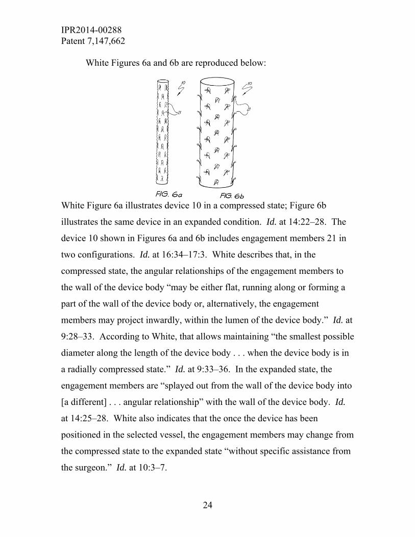
White Figures 6a and 6b are reproduced below:
White Figure 6a illustrates device 10 in a compressed state; Figure 6b
illustrates the same device in an expanded condition. Id. at 14:22–28. The
device 10 shown in Figures 6a and 6b includes engagement members 21 in
two configurations. Id. at 16:34–17:3. White describes that, in the
compressed state, the angular relationships of the engagement members to
the wall of the device body “may be either flat, running along or forming a
part of the wall of the device body or, alternatively, the engagement
members may project inwardly, within the lumen of the device body.” Id. at
9:28–33. According to White, that allows maintaining “the smallest possible
diameter along the length of the device body . . . when the device body is in
a radially compressed state.” Id. at 9:33–36. In the expanded state, the
engagement members are “splayed out from the wall of the device body into
[a different] . . . angular relationship” with the wall of the device body. Id.
at 14:25–28. White also indicates that the once the device has been
positioned in the selected vessel, the engagement members may change from
the compressed state to the expanded state “without specific assistance from
the surgeon.” Id. at 10:3–7.

IPR2014-00288 Patent 7,147,662
25
One mechanism by which the White device may change from a
compressed state to an expanded state is by “a spring-aided change,” which
occurs when “the material comprising the engagement members has a
‘memory’ of [the angular relationship of the engagement members in the
expanded position] . . . such that the engagement members may ‘spring’ into
that position upon release from the catheter.” Id. at 10:18–23. In that
embodiment, the device is manufactured from alloys “which have the
capacity to ‘memorise’ their manufactured shape, such that the device,
according to this invention, will have a continuous tendency to return to its
original shape following any events which cause it to be temporarily
deformed.” Id. at 7:6–11.
In another embodiment, the change from a radially compressed state
(Figure 6a) to a radially expanded state (Figure 6b) is mediated by thermal
expansion. Id. at 16:34–17:15. In that embodiment, engagement members
21 are cut from a Nitinol frame and heat treated such that the engagement
members “have the capacity, following a rise in temperature, to splay out
from a wall of the device.” Id. at 17:8–11.
ii. Analysis
In asserting that White teaches a permanent curve, Petitioners rely on
Figures 6a, 6b, and the following passage from the reference:

IPR2014-00288 Patent 7,147,662
26
the device body and the engagement members will be such that when the device body is in a radially compressed state, the respective first angular relationships of the engagement members may be either flat, running along or forming a part of the wall of the device body or, alternatively, the engagement members may project inwardly, within the lumen of the device body.
Pet. 50 (citing Ex. 1004, 9:29–33, Figs. 6a, 6b); see id. at 55. Petitioners’
expert, Dr. Loomis, explains that White discloses “four ways in which an
engagement member can change its angular relationship to the device once it
is introduced to the vessel,” including heat-aided change in response to body
temperature and spring aided change in which the member returns to a
memorized shape upon the release of a compressive force. Ex. 1026 ¶ 99.
The angular relationship of the engagement members to the body wall may
be flat “or the engagement members might even project inwardly so the
device maintains the smallest profile possible.” Id. ¶ 100 (citing Ex. 1004,
9:27–10:2.)
Petitioners argue that White’s spring expansion embodiment “allows
for temporary deformation of the device into a compressed state without
altering the curvature of any protrusion.” Reply 11. We discern no evidence
for this assertion other than Dr. Loomis’s statement that, in the White’s
spring-aided device, “the engagement members that project outwardly when
expanded can ‘project inwardly, within the lumen of the device’ when
compressed.” Ex. 1034 ¶ 22 (quoting Ex. 1004, 9:27–33). We do not find
Dr. Loomis’s assertion persuasive. See Am. Acad. of Sci. Tech Ctr., 367
F.3d at 1368 (“[T]he Board is entitled to weigh the declarations [offered in
the course of prosecution] and conclude that the lack of factual corroboration
warrants discounting the opinions expressed in the declarations.”).

IPR2014-00288 Patent 7,147,662
27
Dr. Loomis further asserts that expansion of the White device “is
analogous to the engagement member disclosed in the ’662 patent in Figures
2 and 3, where the engagement member projects inwards from the frame.”
Ex. 1034 ¶ 22; see Reply 11. We are not persuaded that Dr. Loomis’s
comparison to the embodiments shown in Figures 2 and 3 of the ’662 patent
is sufficient, as nothing in the Specification requires that those embodiments
comprise a permanent curve. To the contrary, the permissive language of
the Specification that hook 20 “may be permanently-deformed into the
curved configuration by heat setting the material” (Ex. 1001, 5:60–62
(emphasis added)), indicates that those embodiments may fall outside the
claims ultimately issued. See also id. at 6:7–9 (“With a permanently
deformed hook 20, the hook 20 may still be compressed into alignment with
the frame 22 without losing the preset curve.”).
Dr. Loomis further states that
one skilled in the art would have recognized that the engagement members of Figure 6b, when made of a resilient spring-aided change material such as nitinol, would maintain a permanent curve in both their compressed and expanded positions. Further, it is my opinion that one skilled in the art would have recognized that such spring aided materials, if curved in their uncompressed orientation, would maintain a curve when compressed.
Ex. 1026 ¶ 101; see also Reply 11.
We do not discern, nor does Dr. Loomis adequately explain, how the
angular relationship of White’s engagement members, whether in an
expanded, flat, or inwardly-projection configuration, comports with our
construction of permanent curve. At best, Dr. Loomis identifies changes in
the shape of White’s engagement members in response to temperature or
IPR2014-00288 Patent 7,147,662
28
compressive forces. On their face, such changes are incompatible with a
permanent curve that is a preset curve that maintains a fixed arc throughout
normal use regardless of what configuration the device is in. Dr. Loomis has
not convinced us of a contrary interpretation of the White reference.
Accordingly, we credit Ms. Gold’s testimony that “[n]othing in the
disclosure of White indicates that the engagement members 21 have a
permanent curve.” Ex. 2001 ¶ 59.
iii. Overview of Ostrovsky
Ostrovsky describes a “recoverable thrombosis filter that can be
implanted and securely positioned within a vein at a desired location, and
can be recovered through an endovenous route.” Ex. 1007, Abstract. “The
various components of the filter can be constructed of a class of elastic
materials including nitinol, stainless steel, platinum, tungsten, titanium, and
chromium alloys.” Id. at 10:65–11:1. “The selection of materials will also
determine the flexibility and resiliency of the various members.” Id. at
10:63–65.
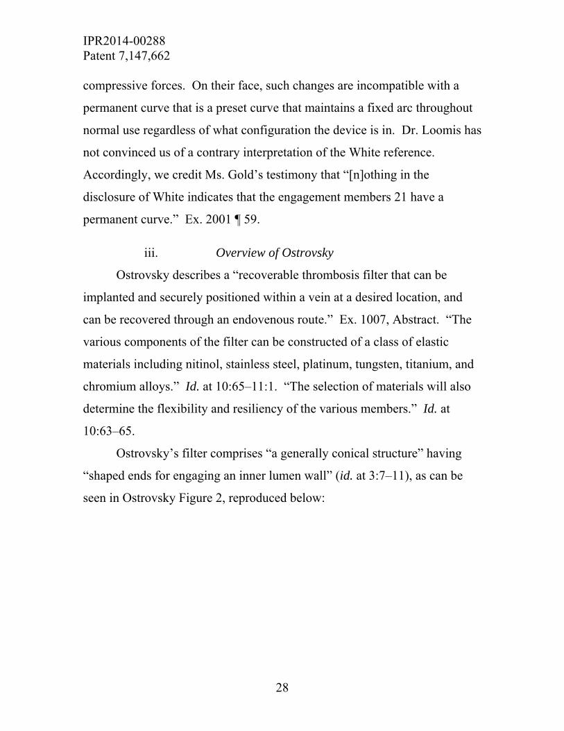
Ostrovsky’s filter comprises “a generally conical structure” having
“shaped ends for engaging an inner lumen wall” (id. at 3:7–11), as can be
seen in Ostrovsky Figure 2, reproduced below:

IPR2014-00288 Patent 7,147,662
29
Figure 2 illustrates Ostrovsky’s filter 44. Id. at 3:66–67. At one end of filter
44, flexible anchoring struts 62 “project outwardly to wall engaging surfaces
64. Projections 66 function to position and hold filter 44 in position when
engaged to an inner vein wall.” Id. at 5:40–43. At the opposite end, filter 44
has “shaped filtering elements 46, each having a mounting end 48 and a wall
engaging end 50.” Id. at 5:31–33. Wall engaging end 50 of element 46 has
projections 52 to engage a vein wall. Id. at 5:31–34, 6:2–3. Ostrovsky
discloses that element 46 may comprise a flat wire having, for example, a
thickness of 0.0006 inch and a width of 0.026 inch, and that differences in
relative thickness relative to width will affect the flexibility of the element.
Id. at 6:10–14.
Ostrovsky Figure 3 is reproduced below:
IPR2014-00288 Patent 7,147,662
30
Figure 3 illustrates a wall engaging end 50 of element 48. Id. at 4:1–2. Wall
engaging end 50, shown in Figure 3, has “a generally curved structure and is
flattened to a desired dimension such that the under surface 84 will slidably
engage an associated vein wall.” Id. at 5:65–6:1. “The thickness [of
engaging end 50] is selected for the desired flexibility.” Id. at 6:1–2.
Ostrovsky discloses that “[a] similar configuration is utilized for the
anchoring elements,” such as anchoring struts 62 shown in Figure 2
(previously presented). Id. at 6:3–4.
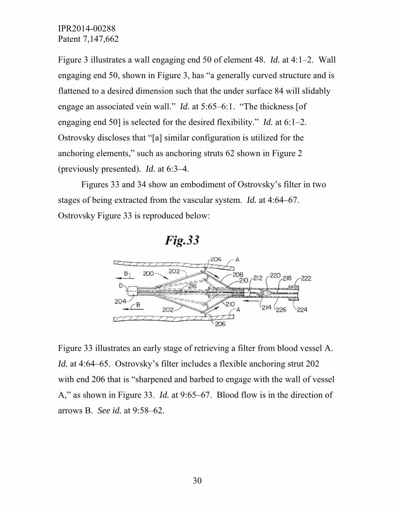
Figures 33 and 34 show an embodiment of Ostrovsky’s filter in two
stages of being extracted from the vascular system. Id. at 4:64–67.
Ostrovsky Figure 33 is reproduced below:
Figure 33 illustrates an early stage of retrieving a filter from blood vessel A.
Id. at 4:64–65. Ostrovsky’s filter includes a flexible anchoring strut 202
with end 206 that is “sharpened and barbed to engage with the wall of vessel
A,” as shown in Figure 33. Id. at 9:65–67. Blood flow is in the direction of
arrows B. See id. at 9:58–62.

IPR2014-00288 Patent 7,147,662
31
Ostrovsky Figure 34 is reproduced below:
Figure 34 illustrates a later stage of retrieving a filter from a vascular
system. Id. at 5:1–2. As shown in Figure 34, element 206, the hook-like
end of strut 202 has been disengaged from the wall of vessel A, brought to a
position adjacent axis D of filter 200, and into contact with inner tube 226.
Id. at 10:34–43.
iv. Analysis
Petitioners contend that Ostrovsky “teaches the use of permanently
curved, pointed hooks on a recoverable thrombosis filter for intraluminal
implantation” (Pet. 26 (citing Ex. 1007, Abstract, Figs. 3 and 24)); that
Ostrovsky Figure 3 “discloses the elongated member (52) bent away from
the frame element (50) wherein the elongated member (52) has a permanent
curve” (id.at 50); and that Ostrovsky Figures 33 and 34 disclose hook-like
elements 206 to anchor the device to the lumen wall firmly, wherein these
elements “maintain a curve in both their compressed and expanded
configurations” (id. at 27; see also Reply 11 (asserting that hooks 206
“maintain an identical curve in each state”)).
Dr. Loomis asserts that Ostrovsky “discloses a curve hook with a
curve and materials that would maintain a permanent curve.” Ex. 1026
¶ 136; see id. ¶ 109 (noting that “outward projection (52) has a permanent
IPR2014-00288 Patent 7,147,662
32
curve”). Although Ostrovsky discloses the use of “elastic materials
including nitinol, stainless steel, platinum, tungsten, titanium, and chromium
alloys” (Ex. 1007, 10:65–11:1 (emphasis added)), Dr. Loomis fails to
explain how the reference teaches the generation of a permanent curve, as is
taught, for example, at column 6, lines 1–4, of the ’662 patent (heating a
Nitinol hook and frame combination “at 550° C. for ten minutes”).
We also take note of Dr. Loomis’s failure to address the forces acting
on any part of an Ostrovsky device alleged to teach or disclose a permanent
curve. For example, as shown in Ostrovsky Figure 33, reproduced above,
hook-like elements 206 are anchored in the wall of blood vessel A as blood
flows through the filter in the direction of arrows B. Figures 33 and 34
further show that in normal use, the filter may be removed from the vessel in
the opposite direction of blood flow. We find no evidence that Dr. Loomis
addressed these or any other forces acting upon the hook-like elements 206
when the Ostrovsky device is deployed in normal use. Accordingly, we find
the evidence of record insufficient to demonstrate that Ostrovsky maintains a
permanent curve as defined herein.
In light of the above, we conclude that Petitioners have not proven by
a preponderance of the evidence that the combination of White and
Ostrovsky renders claims 1–4, 8–12, and 16 unpatentable under 35 U.S.C.
§ 103(a).
d. Obviousness of Claims 7 and 15 in view of White, Ostrovsky, and Lazarus
Petitioners contend that claims 7 and 15 are unpatentable as obvious
in view of White, Ostrovsky, and Lazarus. As discussed above, Petitioners
have not shown that any of these references teach or suggest a permanent
IPR2014-00288 Patent 7,147,662
33
curve as construed herein. We, therefore, conclude that Petitioners have not
proven by a preponderance of the evidence that the combination of White,
Ostrovsky, and Lazarus renders claims 7 and 15 unpatentable under
35 U.S.C. § 103(a).
III. MOTION TO EXCLUDE EVIDENCE
Petitioners move to exclude portions of the deposition transcript of
Dr. Gary L. Loomis as exceeding the scope of rebuttal evidence. Paper 22.
We dismiss Petitioners’ Motion as moot because we do not rely on
any of the objected-to testimony in our final decision.
IV. CONCLUSION
Petitioners have not proven, by a preponderance of evidence, that any
of claims 1–5, 7–13, 15, and 16 are unpatentable over the cited prior art.
V. ORDER
After due consideration of the record before us, it is
ORDERED that claims 1–5, 7–13, 15 and 16 of U.S. Patent No.
7,147,662 are not determined to be unpatentable;
FURTHER ORDERED that Medtronic’s Motion to Exclude Evidence
is dismissed as moot; and
FURTHER ORDED that because this is a final decision, parties to the
proceeding seeking judicial review of the decision must comply with the
notice and service requirements of 37 C.F.R. § 90.2.

IPR2014-00288 Patent 7,147,662
34
FOR PETITIONERS:
James Elacqua Edward Tulin SKADDEN, ARPS, SLATE, MEAGHER & FLOM LLP [email protected] [email protected] FOR PATENT OWNER:
Cary Kappel William Gehris David Petroff DAVIDSON, DAVIDSON & KAPPEL, LLC [email protected] [email protected] [email protected]