triboactive low-friction coatings based on sulfides and ...746440/fulltext01.pdf · this work is...
TRANSCRIPT

ACTAUNIVERSITATIS
UPSALIENSISUPPSALA
2014
Digital Comprehensive Summaries of Uppsala Dissertationsfrom the Faculty of Science and Technology 1183
Triboactive Low-Friction CoatingsBased on Sulfides and Carbides
JILL SUNDBERG
ISSN 1651-6214ISBN 978-91-554-9041-6urn:nbn:se:uu:diva-230989

Dissertation presented at Uppsala University to be publicly examined in Häggsalen,Ångströmlaboratoriet, Lägerhyddsvägen 1, Uppsala, Friday, 31 October 2014 at 09:15 forthe degree of Doctor of Philosophy. The examination will be conducted in English. Facultyexaminer: Professor Jochen M. Schneider (RWTH Aachen University).
AbstractSundberg, J. 2014. Triboactive Low-Friction Coatings Based on Sulfides and Carbides.Digital Comprehensive Summaries of Uppsala Dissertations from the Faculty of Science andTechnology 1183. 86 pp. Uppsala: Acta Universitatis Upsaliensis. ISBN 978-91-554-9041-6.
For sustainable development, it is highly important to limit the loss of energy and materials inmachines used for transportation, manufacturing, and other purposes. Large improvements canbe achieved by reducing friction and wear in machine elements, for example by the applicationof coatings. This work is focused on triboactive coatings, for which the outermost layer changesin tribological contacts to form so-called tribofilms. The coatings are deposited by magnetronsputtering (a physical vapor deposition method) and thoroughly chemically and structurallycharacterized, often theoretically modelled, and tribologically evaluated, to study the connectionbetween the composition, structure and tribological performance of the coatings.
Tungsten disulfide, WS2, is a layered material with the possibility of ultra-low friction. Thiswork presents a number of nanocomposite or amorphous coatings based on WS2, which combinethe low friction with improved mechanical properties. Addition of N can give amorphouscoatings consisting of a network of W, S and N with N2 molecules in nanometer-sized pockets,or lead to the formation of a metastable cubic tungsten nitride. Co-deposition with C can alsogive amorphous coatings, or nanocomposites with WSx grains in an amorphous C-based matrix.Further increase in coating hardness is achieved by adding both C and Ti, forming titaniumcarbide. All the WS2-based materials can provide very low friction (down to µ<0.02) by theformation of WS2 tribofilms, but the performance is dependent on the atmosphere as O2 andH2O can be detrimental to the tribofilm functionality.
Another possibility is to form low-friction tribofilms by tribochemical reactions between thetwo surfaces in contact. Addition of S to TiC/a-C nanocomposite coatings leads to the formationof a metastable S-doped carbide phase, TiCxSy, from which S can be released. This enables theformation of low-friction WS2 tribofilms when a Ti-C-S coating is run against a W counter-surface. Reduced friction, at a moderate level, also occurs for steel counter-surfaces, likely dueto formation of beneficial iron sulfide tribofilms.
The studied coatings, whether based on WS2 or TiC, are thus triboactive, with the ability toform low-friction tribofilms in a sliding contact.
Keywords: coatings, thin films, tribology, tungsten disulfide, transition metal dichalcogenide,nanocomposite, TiC/a-C, tribofilms, PVD, XPS, HAXPES, XRD, SEM, TEM, Ramanspectroscopy, nanoindentation
Jill Sundberg, Department of Chemistry - Ångström, Inorganic Chemistry, Box 538, UppsalaUniversity, SE-751 21 Uppsala, Sweden.
© Jill Sundberg 2014
ISSN 1651-6214ISBN 978-91-554-9041-6urn:nbn:se:uu:diva-230989 (http://urn.kb.se/resolve?urn=urn:nbn:se:uu:diva-230989)

List of papers
This thesis is based on the following papers, which are referred to in the text by their Roman numerals.
I Understanding the effects of sputter damage in W-S thin films by HAXPES J. Sundberg, R. Lindblad, M. Gorgoi, H. Rensmo, U. Jansson, A. Lindblad Applied Surface Science 305 (2014) 203-213
II Amorphous W-S-N thin films: The atomic structure behind ultra-low friction L. Isaeva, J. Sundberg, S. Mukherjee, C.J. Pelliccione, A. Lindblad, C.U. Segre, U. Jansson, D. D. Sarma, O. Eriksson, K. Kádas Accepted for publication in Acta Materialia
III Influence of composition, structure and testing atmosphere on the tribological performance of W-S-N coatings J. Sundberg, H. Nyberg, E. Särhammar, T. Nyberg, S. Jacobson, U. Jansson Submitted
IV Influence of Ti addition on the structure and properties of low-friction W-S-C coatings J. Sundberg, H. Nyberg, E. Särhammar, F. Gustavsson, T. Kubart, T. Nyberg, S. Jacobson, U. Jansson Surface and Coatings Technology 232 (2013) 340-348
V Extreme friction reductions during initial running-in of W-S-C-Ti low-friction coatings H. Nyberg, J. Sundberg, E. Särhammar, F. Gustavsson, T. Kubart, T. Nyberg, U. Jansson, S. Jacobson Wear 302 (2013) 987-997

VI Tribochemically active Ti-C-S nanocomposite coatings J. Sundberg, H. Nyberg, E. Särhammar, K. Kádas, L. Wang, O. Eriksson, T. Nyberg, S. Jacobson, U. Jansson Materials Research Letters 1 (2013) 148-155
VII Tribochemical formation of sulphide tribofilms from a Ti-C-S coating sliding against various counter surfaces H. Nyberg, J. Sundberg, E. Särhammar, T. Nyberg, U. Jansson, S. Jacobson Submitted
VIII Formation of 2D transition metal dichalcogenides on TiC1-xAx surfaces (A= S, Se, Te): A theoretical study K. Kádas, J. Sundberg, U. Jansson, O. Eriksson Journal of Materials Research 29 (2014) 207-21
Reprints were made with permission from the respective copyright holders.

Author’s contributions to the papers
In general I have been responsible for the chemical and structural characterization of as-deposited and tribologically tested coatings, and the evaluation of their mechanical properties. I have planned and taken part in, but not been main responsible for, the deposition of coatings. I have not performed tribological testing or surface topography measurements, but been heavily involved in the planning and evaluation of the tribological tests. I have not performed theoretical calculations, but have been involved in their conception and planning, and the interpretation of their results.
Paper I Major part of planning, experiments, discussion and writing.
Paper II Large part of planning, parts of characterization, large part of discussion and writing.
Paper III Large part of planning, all pre-test and some post-test characterization, large part of discussion and writing.
Paper IV Major part of planning, all pre-test and some post-test characterization, large part of discussion and writing.
Paper V Part of planning, part of characterization, part of discussion and writing.
Paper VI Major part of planning, all pre-test and some post-test characterization, large part of discussion, major part of writing
Paper VII Large part of planning, characterization, discussion and writing.
Paper VIII Part of planning and discussion, provided input for calculations, minor part of writing.

Related work
Mechanisms for compositional variations of coatings sputtered from a WS2 target E. Särhammar, E. Strandberg, J. Sundberg, H. Nyberg, T. Kubart, S. Jacobson, U. Jansson, T. Nyberg Surface and Coatings Technology 252 (2014) 186-190
Solution-based synthesis of AgI coatings for low-friction applications J. Sundberg, F. Mao, A. M. Andersson, U. Wiklund, U. Jansson Journal of Materials Science 48 (2013) 2236-2244

Contents
Introduction ..................................................................................................... 9
Coating materials .......................................................................................... 10 Transition metal dichalcogenide-based coatings ...................................... 10 Carbon and carbide coatings .................................................................... 16
Tribology and tribological coatings .............................................................. 19 Tribological concepts ............................................................................... 19 Tribological coatings ................................................................................ 21
Coating deposition ........................................................................................ 23 Magnetron sputtering ............................................................................... 23
Characterization and evaluation .................................................................... 26 Microscopy ............................................................................................... 26 Diffraction ................................................................................................ 29 Spectroscopy ............................................................................................ 31 Other characterization techniques ............................................................ 36 Tribological evaluation ............................................................................ 38
Theoretical methods ...................................................................................... 40
Results ........................................................................................................... 43 WS2-based materials ................................................................................. 43 Ti-C-S ....................................................................................................... 61 Low-friction by WS2 tribofilms ............................................................... 68
Conclusions ................................................................................................... 70 Outlook ..................................................................................................... 72
Sammanfattning på svenska .......................................................................... 74
Acknowledgements ....................................................................................... 76
References ..................................................................................................... 78

Abbreviations
a-C amorphous carbon a.u. arbitrary units at.% atomic percent AFM atomic force microscopy CPA coherent potential approximation DC direct current DFT density functional theory DOS density of states DLC diamond-like carbon Eb, Ek binding energy, kinetic energy EDS energy-dispersive X-ray spectroscopy EELS electron energy loss spectroscopy EFTEM energy-filtered TEM EMTO exact muffin-tin orbitals EP extreme pressure EXAFS extended X-ray absorption fine structure FIB focused ion beam GI-XRD grazing incidence XRD HAXPES hard X-ray photoelectron spectroscopy HRTEM high resolution TEM HT high temperature MD molecular dynamics nc nanocrystalline NEXAFS near edge X-ray absorption fine structure PVD physical vapor deposition RH relative humidity RT room temperature SEM scanning electron microscopy TEM transmission electron microscopy TMD transition metal dichalcogenide VASP Vienna ab initio simulation package XANES X-ray absorption near edge structure XAS X-ray absorption spectroscopy XPS X-ray photoelectron spectroscopy XRD X-ray diffraction XRR X-ray reflectivity

9
Introduction
A major challenge for modern technology is sustainable development, and how to cope with limited resources of materials and energy. Finding new ways of producing energy is often discussed, but another important aspect is to limit the use of energy. Tribology is the science concerning topics such as friction and wear, which are ever-present phenomena intimately connected with energy and wear losses. For example, it is estimated that more than ¼ of the fuel energy in passenger cars is used to overcome friction, and similar situations should be found in other vehicles and in all sorts of industrial production. Reduction of friction and wear thus offers large possibilities of saving energy and materials by reducing the energy needed for operation, as well as increasing component lifetimes.
Wear and friction are surface phenomena, and a component can therefore be tribologically optimized by suitable design of the surface. One way to achieve this is to apply a coating, an approach which has been used in this work. The thickness of the coating is often only a few micrometers, i.e. a few thousandths of a millimeter, or a few percent of the thickness of a human hair. Still, it can vastly decrease the friction and wear. The focus of this work has been triboactive coatings, which change and adapt when sliding against another surface, leading to the formation of a slightly different material on the outermost part of the coating. This so-called tribofilm is usually only a few tens of nanometers thick, but has a significant effect on coating performance.
In this work, a number of sulfide- and/or carbide-based low-friction coatings have been investigated. The aim has been to understand the connection between the composition and the structure of the coatings, how they change in a tribological contact (by the formation of tribofilms), and the tribological performance in terms of friction and wear. The coatings have thus been studied on the microscopical scale, to determine what atoms makes up the material and how they are arranged, as well as on the macroscopical scale when their performance has been evaluated.
The background of the scientific questions is discussed in the following chapter, as well as the issues addressed in the different papers constituting the basis of this thesis.

10
Coating materials
Transition metal dichalcogenide-based coatings Transition metal dichalcogenides (TMDs) are compounds with the general formula MeX2. In this work, the term is used to describe compounds where the metal Me is Mo or W and the chalcogen X is S or Se (or Te, in paper VIII). In tribological contexts, MoS2 is the most well-known compound of the group, but WS2 is also widely studied. These TMDs exhibit similar properties, which are closely related to their layered and highly anisotropic structure. They are built up from layers of metal and chalcogen atoms, where a sheet of metal atoms is sandwiched in between two sheets of chalcogen atoms, forming what will be referred to as a sandwich layer (see Figure 1). Each metal atom is coordinated by a trigonal prism of chalcogen atoms.1 The bonds between metal and chalcogen atoms are strong, and a molecular orbital approach shows that all low-energy orbitals of the metal and the chalcogen are involved in bonds within the sandwich layer.2 Between the layers there are only van der Waals interactions, meaning that the bonding in this direction is weak. Unless there are defects, the (001) basal plane surface is unreactive. Dangling bonds are found on the plane edges.
Figure 1. Structure of WS2, with 2H-WS2 in 2D and 3D view (left and middle), and turbostratically stacked WS2 in 3D view (right). W atoms are dark grey and S atoms are light grey. The c axis is vertical in the plane of the paper.

11
Given the weak interactions between the sandwich layers, it is not surprising that they can be stacked in different ways. The most common form has a stacking sequence of two sandwich layers, giving a hexagonal symmetry, and it is denoted 2H-MeX2. A stacking sequence of three sandwich layers results in the lesser-known rhombohedral form 3R-MeX2.
1, 3, 4 Furthermore, disordered stacking is possible. In so-called turbostratic stacking, which is also known for graphite, the sandwich layers are parallel but more or less randomly rotated around the c axis, as imaged in Figure 1.5, 6
The weak bonding between the sandwich layers makes the shear strength parallel to the planes very low, and TMDs can be used as solid lubricants. MoS2, known as molybdenite when occurring naturally as a mineral, has been used as such for centuries, although it has been mistaken for graphite because of their similarities on a macroscopical scale.7 Much of the work on MoS2, and later also on WS2, has been focused on vacuum or space applications, since the TMDs are known to perform best in these environments. This highlights an important difference between graphite and TMD lubrication, in that graphite is dependent on the presence of intercalating species (such as H2O) to obtain low friction, while the TMDs are intrinsic lubricants and perform best in the absence of such contaminations.8 Reactive species such as O2 can oxidize the TMDs to the corresponding oxides (WO3, MoO3) which do not possess the same low-friction properties. Furthermore, the presence of H2O has been suggested to increase the shear strength of TMDs by strengthening the bonds between the sandwich layers, thereby causing higher friction.9-12 While it is well-known that WS2-based coatings perform better in inert atmospheres than in ambient air, the respective effects of H2O and O2 are less studied. Furthermore, the possibility of low-friction by WS2 lubrication not only varies with the atmosphere, but also with the composition and structure of the coating material. These questions were addressed in paper III, where a number of W-S-N coatings were characterized and described, and their tribological performance was evaluated in four different atmospheres.
Besides the turbostratic stacking and the low-friction properties, another analogy between carbon and TMDs is found in the formation of nanotubes and fullerene or fullerene-like particles.13 Inorganic fullerene-like particles, often called IF-MoS2 and IF-WS2, have been studied for low-friction applications.14 Following the intense interest for graphene in recent years, TMDs have also gained attention as analogous two-dimensional materials.15 Some tribological studies have been carried out,16 but nanoscale friction is perhaps of more academic than practical interest, and other aspects such as electrical properties should play a larger role in this context. The sulfides and selenides of Mo and W are already established as thin film materials for solar cells and similar applications, where their electrical and optical properties and their anisotropy are considered advantageous.

12
Although the term TMD in this work is used to refer to sulfides and selenides of Mo and W, there are a large number of MeX2 compounds. Many of them are layered and consist of X-Me-X sandwich layers, where the coordination around the Me atoms can be trigonal prismatic (as for MoS2 and WS2) or octahedral.17 In some compounds, often tellurides such as WTe2, the layers are distorted and buckled, leading to a less lubricious behavior than for, for example, WS2 and WSe2.
18 However, many compounds with flat layers still do not provide low friction. Examples are TiS2, and the disulfides of group 5 elements V, Nb and Ta.19 A explanation based on molecular orbital theory has been suggested, in that the dz
2 orbitals of group 6 elements Mo and W are filled, meaning that all accessible orbitals of metal and chalcogen atoms are used for bonding within the sandwich unit.2 For group 4 or 5 elements, however, these orbitals are not filled, allowing for interactions with neighboring sandwiches.2 Furthermore, the Me-X coordination and the stacking of the X-Me-X sandwiches is different, which has been suggested to cause a difference in electric charges. For dichalcogenides of group 6 elements there is electrostatic repulsion between the X surfaces of neighboring sandwiches, while for group 4 or 5 dichalcogenides there is electrostatic attraction.2, 19 A change in the electron distribution and hence the electrostatic forces due to H2O molecules has also been suggested as the reason for the increased shear strength of group 6 disulfides in humid conditions.18
Sulfides with structures other than layered sandwich structures can also be used for friction reduction purposes, although they do not offer the same excellent low-friction properties as the previously described compounds. Examples are iron sulfides such as FeS2, FeS and Fe1-xS. Iron sulfide coatings reducing friction and wear can be deposited by, for example, sulfurization of an iron surface or plasma spraying.20 Formation of iron sulfides is also a common function of S-containing extreme pressure (EP) additives to prevent contact between bare steel surfaces, and a similar principle involving Ti-C-S coatings and steel counter-surfaces is studied in paper VII.
Pure TMD coatings W-S or Mo-S coatings can be sputtered non-reactively from a compound target, or reactively from a metallic target and H2S(g). The methods give similar results, which vary with different deposition parameters. The resulting coatings are often substoichiometric in sulfur, and could thus be referred to as MeSx with x < 2.21-24 According to the phase diagrams, the stability ranges for the disulfides are narrow,25, 26 but the deposition does not take place at thermodynamical equilibrium (see “Coating deposition” section on p. 23). The high quench rates can lead to non-stoichiometric compositions
13
and metastable structures, and the coatings may be nanocrystalline or amorphous.21, 27
The stoichiometric variation in coatings sputtered from WS2 targets has been a topic for related studies,24 but is also seen for coatings in the current work. The composition and structure of amorphous and crystalline W-S coatings have been described in paper I, which also addresses a related problem often found when characterizing such coatings. For surface-sensitive analysis methods such as X-ray photoelectron spectroscopy (XPS), the analysis is often preceded by surface cleaning by sputter etching. Sputter deposition and sputter etching are based on the same phenomenon, and in both cases W and S atoms behave differently from each other. In the case of sputter cleaning prior to analysis, the material is thus changed by the etching, and the undisturbed W-S coatings cannot be probed. It is known for TMD single crystals that S is preferentially sputtered during sputter etching,28-31 and so similar effects should be found for TMD-based coatings, although this is rarely considered. In paper I, a type of XPS with a large information depth was used to study W-S coatings to describe the undisturbed coating material and the effects of damage caused by sputter etching.
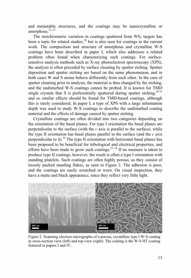
Crystalline coatings are often divided into two categories depending on the orientation of the basal planes. For type I orientation the basal planes are perpendicular to the surface (with the c axis is parallel to the surface), while the type II orientation has basal planes parallel to the surface (and the c axis perpendicular to it).32 The type II orientation with horizontal basal planes has been proposed to be beneficial for tribological and electrical properties, and efforts have been made to grow such coatings.33, 34 If no measure is taken to produce type II coatings, however, the result is often a type I orientation with standing platelets. Such coatings are often highly porous, as they consist of loosely packed standing flakes, as seen in Figure 2. The adhesion is poor, and the coatings are easily scratched or worn. On visual inspection, they have a matte and black appearance, since they reflect very little light.
Figure 2. Scanning electron micrographs of a porous, crystalline type I W-S coating in cross-section view (left) and top-view (right). The coating is the W-S HT coating featured in papers I and IV.

14
The X-ray diffractograms for type I coatings have a characteristic appearance, dominated by two peaks that are asymmetric with a tail towards higher angles in GI-XRD. These peaks are found at angles approximately corresponding to the (100) and (110) reflections. Turbostratic stacking, i.e. disorder around the c axis (visualized in Figure 1), gives composite peaks indexed as (10l) and (11l), or only (10) and (11), instead of discrete peaks for different l.6, 21, 27 Coatings of type I orientation may have a nucleation layer of type II orientation, which can be observed in the diffractogram as low-intensity (00l) reflections.21, 35
TMD-based coatings The mechanical properties of pure TMD coatings in many cases have room for improvement, and a common approach has been to mix TMDs with other materials. For example TMDs have been co-deposited with materials known to have beneficial mechanical properties, such as TiB2,
36 TiN,37, 38 CrN,39 or Sb2O3
40. The aim is then to create a hard coating with solid lubricant reservoirs of TMD. A slightly different, and widely used, route is to co-deposit TMD with a metal, possibly in rather small amounts – the term “doping” is often used. A large number of metals and alloys (see Figure 3) have been added to TMD coatings in this manner.41-49 In general, the addition of a metal leads to disruption of the crystallinity of the TMD phase, thereby increasing the hardness, adhesion and density of the coating. The resulting coatings are thus often amorphous or nanocrystalline, and even though a segregated metal phase may form for higher metal contents this is usually not an objective. The most well-known combination is that of MoS2 and Ti, which was presented by the group of D.G. Teer48 and has been commercialized by Teer Coatings Ltd as so-called MOST coatings.
The function of the added element is to improve the mechanical properties by disrupting the crystallinity of the TMD. The TMD phase is still responsible for the lubrication and low-friction properties, and in this aspect the added element should preferably not interfere. For some reason, metals seem to have been the most popular choice for the additive element. However, they are not necessarily ideal, as many metals have poor frictional properties. Furthermore, many metals are prone to oxide formation, and although some metal oxides are considered more or less lubricious, many are abrasive and detrimental in a sliding contact. A promising alternative is then to add a non-metallic element, and both C and N have been combined with TMDs. The oxides of these elements are gaseous, meaning that they can easily leave the contact, and not disturb the WS2 lubrication.
In 1999, Voevodin et al. presented nanocomposite WC/DLC/WS2 coatings, deposited by laser ablation from a combined WS2-graphite target.50,
51 The idea was to combine the low friction and wear resistance of amorphous diamond-like carbon (DLC) with the wear resistance of WC and

15
solid lubrication of WS2. The research was aimed at aerospace applications, meaning that the materials should function in terrestrial conditions before launching as well as in space. Given that DLC is known to provide low friction in humid environments, while WS2 is a good lubricant in dry conditions, a behavior with different friction mechanisms in different environments was suggested, and the coatings were dubbed “chameleon coatings”.52
Figure 3. Elements co-deposited with TMDs (marked in grey).
In a similar approach, Nossa and Cavaleiro presented W-S-C and W-S-N coatings in 2001.53 While Voevodin et al. started from DLC and W-doped DLC and added a WS2 phase for lubrication, Nossa and Cavaleiro instead gradually added C or N to WS2, in an approach similar to the one previously described for metal addition. W-S-C coatings were deposited by reactive sputtering from a WS2 target and CH4(g),53-57 by co-sputtering from WS2 and C targets,56 and from a C target partly covered by WS2 pellets,58, 59 and coatings deposited by different methods were found to be similar. With increasing C content, the microstructure changed from columnar WSx to a dense nanocomposite coating, consisting of an amorphous carbon matrix with WS2 nanocrystallites, and possibly also a W-C phase. The hardness increased with the addition of C, reaching a maximum at around 40 at.% and then decreasing somewhat on further carbon addition.
W-S-N coatings were found to be similar to W-S-C coatings, with the addition of N leading to a decrease in coating crystallinity, and increase in hardness and wear resistance.53-55, 57, 60 In later work, Gustavsson et al. demonstrated ultra-low friction properties for an amorphous W-S-N coating with a high N content (34 at.%).61 For W-S-N coatings, there should not be a matrix phase analogous to the amorphous carbon in W-S-C coatings, and the phase composition and bonding arrangements for higher N contents was unclear. Therefore, paper II provides a detailed structural description of amorphous W-S-N coatings, which were studied by theoretical as well as experimental methods. Amorphous as well as nanocrystalline W-S-N

16
coatings were then studied in paper III, in order to elucidate the connection between coating composition and structure on one hand, and tribological function and performance on the other. The related W-S-C coatings were studied in papers IV and V, also to provide a detailed description of the structure and composition of such materials, and how this affects the performance as low-friction coatings.
Continuing the work on W-S-C coatings, Polcar et al. studied the effect of Cr addition on the microstructure and behavior.62 The added Cr was found to be present mainly as a metallic phase, and although it slightly increased the hardness of the coatings, the addition of Cr was not considered to improve the tribological properties. To improve the mechanical properties, namely the hardness, of W-S-C coatings, a strongly carbide-forming metal should be a better option. In papers IV and V, Ti was added to W-S-C coatings and the material was described and evaluated with respect to the tribological properties. The quaternary material, and the effect of the deposition parameters on its composition and structure, was described and tribologically evaluated in paper IV, while paper V focused more closely on the friction mechanisms for select W-S-C and W-S-C-Ti coatings.
Carbon and carbide coatings Diamond-like carbon (DLC) has gained immense interest as a coating material for various applications in the last decades. It is a metastable form of amorphous carbon, where a large part of the carbon atoms are sp3-hybridized, i.e. tetrahedrally coordinated, like in diamond. Most DLC variants also contain sp2-hybridized carbon, and depending on the deposition method, hydrogen can be incorporated into the structure. A large proportion of sp3 carbon leads to properties similar to those of diamond, such as high hardness and chemical inertness, and is generally considered desirable.63
DLC is often used for protective coatings since they can have a high hardness and Young’s modulus, like diamond, while also being smooth and lacking grain boundaries.63 For tribological applications, DLC coatings can give low friction levels in sliding contacts, under lubricated as well as unlubricated conditions. The performance is, however, heavily dependent on the coating structure and composition, and on the testing atmosphere and other conditions.63
The properties of DLC coatings can also be tuned by doping with other elements. A large number of metals, mainly transition metals, have been alloyed with DLC, often by reactive sputtering from a metallic target and a hydrocarbon gas.64 The doping can in many cases improve the tribological and mechanical properties, which can be ascribed to the reduced compressive stresses, and improved adhesion. For metals prone to carbide formation, such as Ti and W, the resulting coating often contains
17
nanocrystalline carbide grains in an amorphous carbon matrix, comparable to DLC. The presence of carbide nanocrystallites can improve the wear resistance of the coating.64 In industrial applications, DLC can be combined with metal in multilayers of Me-DLC and DLC.
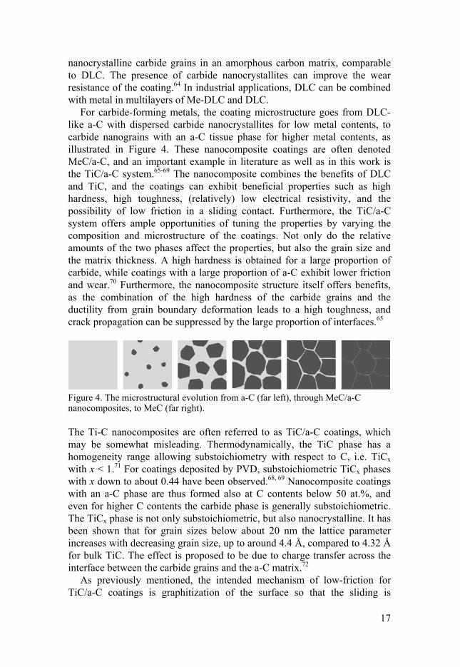
For carbide-forming metals, the coating microstructure goes from DLC-like a-C with dispersed carbide nanocrystallites for low metal contents, to carbide nanograins with an a-C tissue phase for higher metal contents, as illustrated in Figure 4. These nanocomposite coatings are often denoted MeC/a-C, and an important example in literature as well as in this work is the TiC/a-C system.65-69 The nanocomposite combines the benefits of DLC and TiC, and the coatings can exhibit beneficial properties such as high hardness, high toughness, (relatively) low electrical resistivity, and the possibility of low friction in a sliding contact. Furthermore, the TiC/a-C system offers ample opportunities of tuning the properties by varying the composition and microstructure of the coatings. Not only do the relative amounts of the two phases affect the properties, but also the grain size and the matrix thickness. A high hardness is obtained for a large proportion of carbide, while coatings with a large proportion of a-C exhibit lower friction and wear.70 Furthermore, the nanocomposite structure itself offers benefits, as the combination of the high hardness of the carbide grains and the ductility from grain boundary deformation leads to a high toughness, and crack propagation can be suppressed by the large proportion of interfaces.65
Figure 4. The microstructural evolution from a-C (far left), through MeC/a-C nanocomposites, to MeC (far right).
The Ti-C nanocomposites are often referred to as TiC/a-C coatings, which may be somewhat misleading. Thermodynamically, the TiC phase has a homogeneity range allowing substoichiometry with respect to C, i.e. TiCx with x < 1.71 For coatings deposited by PVD, substoichiometric TiCx phases with x down to about 0.44 have been observed.68, 69 Nanocomposite coatings with an a-C phase are thus formed also at C contents below 50 at.%, and even for higher C contents the carbide phase is generally substoichiometric. The TiCx phase is not only substoichiometric, but also nanocrystalline. It has been shown that for grain sizes below about 20 nm the lattice parameter increases with decreasing grain size, up to around 4.4 Å, compared to 4.32 Å for bulk TiC. The effect is proposed to be due to charge transfer across the interface between the carbide grains and the a-C matrix.72
As previously mentioned, the intended mechanism of low-friction for TiC/a-C coatings is graphitization of the surface so that the sliding is

18
accommodated within this easily sheared material.68, 73 A large amount of the a-C phase is thus usually connected to a better tribological performance, with lower friction and wear.70 Furthermore, it is also possible to enhance the graphite lubrication properties by changing the chemistry of the coating material. The TiC phase can be doped with a weakly carbide-forming metal such as Al, forming a metastable substitutional solid solution.74 Al forms only weak bonds to C, and its incorporation favors the formation of a-C during deposition, and the release of C in a tribological contact. Doping with Al can thus enhance the formation of beneficial C-based tribofilms.74
A similar approach could be imagined for forming tribofilms of other low-friction materials, for example TMDs. So-called extreme pressure (EP) additives are often added to oils to reduce friction and wear, and many of them contain S. In reactions activated by high local temperatures and pressures in a tribological contact, they react to form tribologically beneficial films containing sulfides of metals from the additives (such as Mo) or from the surface (such as Fe).75 Formation of WS2, causing friction reductions, has been observed for W-containing DLC coatings in oil with EP additives and in diesel fuel containing trace amounts of S.76, 77 However, the S concentration in fuels and lubricants should be limited for environmental reasons. The total amount of S in the system is large if it is present in the liquid, and a better approach would be to supply S from a coating, so that it is released in small amounts, and only where and when it is needed. This approach was explored by S-doping of TiC/a-C coatings, as described in papers VI and VII. The S should be expected to substitute for C, unlike Al which substitutes for Ti. In both cases, the doped carbide is metastable, and the deposition is made possible by the non-equilibrium conditions of the deposition method (see “Coating deposition” section on p. 23). On activation by, for example, the high local temperatures and pressures in a sliding contact, the material can change – for Al-doped coatings by release of C, and for S-doped coatings by release of S. The possibility of expanding this concept to the heavier chalcogens (Se and Te) was studied in paper VIII.

19
Tribology and tribological coatings
Tribology is the science of interacting surfaces in relative motion, named for ancient Greek tribos, meaning “to rub”. It concerns topics such as friction, wear and lubrication, and is often dealt with in connection with mechanical engineering. However, tribology is not only important for machine elements and tools, but in most aspects of our daily lives - walking, wearing contact lenses, or riding a bicycle all involve tribological phenomena, even though we are often not aware of it. In industrial applications, on the other hand, awareness of tribological aspects is crucial. Lowering of friction and wear can lower the consumption of energy and materials, increase component lifetimes, decrease operating costs, improve performance, decrease environmental footprints, and so on. Tribological optimization is thus highly important for economical as well as environmental reasons.
In 1966, the so-called Jost report, in which the term tribology was coined, estimated that in the UK, more than 500 million GBP could be saved each year by tribological improvements.78 Similar reports were then presented for example for the US (100 billion USD in 1974) and for West Germany (5 billion DM in 1976).79 The numbers are of course only estimations, but in all cases, amounts corresponding to some percent of the gross domestic product could be saved by tribological means. A more specific and recent example concerning passenger cars estimates that 28% of the fuel energy is consumed by friction losses in the engine, transmission and tires. On a global level, the use of friction-reducing technologies could lead to fuel savings of several hundred billion liters, and CO2 emission reductions of several hundred million tons.80 Surface modification to improve the tribological performance of components in, for example, the automotive industry thus has the possibility of significantly reducing our negative impact on the environment.
Tribological concepts Friction is the phenomenon of resistance towards relative movement of surfaces. Friction is quantified using the so-called friction coefficient µ. It is defined as the ratio between the tangential friction force and the normal force (visualized in Figure 5):

20
=
The friction between surfaces in relative motion is called dynamic or kinetic friction, while resistance to the onset of sliding is called static friction. In this work, the term friction refers to the dynamic friction of two surfaces sliding against each other. Sliding friction can be divided into an adhesive (µA) and a ploughing (µP) component: = + μ
The adhesive component is ascribed to shear of material in the areas of contact, and the ploughing component to protrusions of the harder surface “ploughing” through material of the softer surface.
When discussing friction and friction coefficients, it must be remembered that friction is a system parameter, and not a property of a specific surface or material. The measured friction is dependent on the materials and topographies of both surfaces, as well as on the atmosphere and lubricant, if any. Furthermore, in a test situation, parameters such as load, speed and geometry of movement will affect the tribological conditions and the measured friction coefficient.
Figure 5. Schematic picture showing the normal (FN) and friction (FF) forces on a sliding object.
Wear is the removal of material from its original position. For sliding contacts, the wear is often quantified in terms of the specific wear rate (K’), which is the worn volume divided by the sliding distance (S) and the applied load (FN): =
The wear rate has the unit of m2N-1, but is usually given as mm3N-1m-1 or µm3N-1m-1.

21
It might be expected that high friction correlates to high wear, and low friction to low wear, but this is not necessarily the case. An example is if one of the surfaces consists of an easily sheared and relatively soft material such as WS2, leading to low friction but high wear.
Lubrication is the use of a lubricant to reduce friction between surfaces. Oils are common liquid lubricants, and can be either base oils or formulated oils containing various additives. Solid lubricants are materials such as graphite and transition metal dichalcogenides (TMDs), where the latter are of great importance for the work presented in this thesis. However, in this work the TMD is not added as a lubricant between surfaces, but it is incorporated into the coating or formed in the contact. The presented tribological studies concern unlubricated contacts, meaning that two surfaces are run dry against each other. In practice, lubricated contacts are very common, but there are situations when oils or other lubricants are undesirable. Furthermore, there is usually some contact between the surfaces also in lubricated systems.
Tribofilms, or tribolayers, are formed on surfaces as an effect of structural or chemical changes of the materials in contact. On a microscopical scale, the forces in the contact spots are large, leading to high pressures and temperatures, which is likely to induce changes in the material. So-called transfer films are, as the name implies, formed when material from one surface is transferred to the other. The tribofilms are highly important to the tribological behavior of a system, and to understand and control their function is a key aspect in tribological optimization.
Tribological coatings When designing mechanical components, a large number of aspects are taken into consideration, many of which concern mechanical bulk properties and how to avoid for example fatigue, fracture or yielding. Unfortunately, materials that are suitable in these aspects are not necessarily beneficial from a tribological point of view. A common solution to this problem is to modify the surface, so that the materials in the bulk and on the surface are optimized for their respective role. One way of modifying the surface is to apply a coating. Even if the coating only has a thickness of a few µm (i.e. only a few percent of the diameter of a human hair), it can drastically change the properties of the surface. An example of great importance in Swedish industry is the deposition of hard, wear-resistant coatings onto cemented carbide cutting tools. In this work, the main interest is low-friction coatings, with a sufficient wear resistance. The terms coating and (thin) film can be used interchangeably, but coating is favored in this text, in order to avoid confusion with tribofilms.

22
On closer inspection, it is also possible to distinguish between the bulk and surface properties of the coating, as described in Figure 6. A hard surface can decrease the friction by decreasing the area of the contact spots and the ploughing of asperities. However, to minimize the friction, the shear strength in the interface should be low, which is often found for soft materials. A hard surface with good load-bearing capacity and a very thin layer of a soft, easily-sheared material is a promising solution. The low-friction material can be a tribofilm, which can even be in the nm range and still give low friction. This concept is used for example in carbon-based coatings, where lubricating graphite is formed as a tribofilm on top of a hard and wear-resistant coating. A similar concept with the formation of WS2 tribofilms is used in this work.
Figure 6. A coating on top of a substrate, with a formed tribofilm on the outermost surface.
As previously mentioned, the local situation in a tribological contact is often extreme, and the probability for changes of the materials is high. Coatings that spontaneously form and maintain tribofilms with desirable properties, can be defined as triboactive. This means that they change and form beneficial tribofilms by for example chemical reactions, material transfer or structural rearrangements, and preferably do so throughout the lifetime of the component so that the tribofilm is maintained. This approach has been used in the current work, mainly by designing nanocomposite or amorphous coatings from which low-friction WS2 tribofilms are formed in a tribological contact.

23
Coating deposition
There are many different methods to deposit coatings onto a surface. Vapor deposition methods are often grouped into two main categories: chemical vapor deposition (CVD) and physical vapor deposition (PVD). In CVD, the molecular precursors undergo chemical reactions to form the desired coating material, while in PVD the atoms of the material are moved from a source to a substrate. The displacement of atoms in PVD can be achieved by vaporizing the material by for example a laser beam, an electron beam, or a resistance heater, or by creating an electrical arc. Another possibility is to use a plasma to eject atoms from the source material in a process called sputtering. A variety of this technique, namely magnetron sputtering, has been used in this work.
Magnetron sputtering Sputtering is the process when atoms are ejected from a material as an effect of bombardment by energetic particles. The sputtering effect can be employed for deposition of coatings. Atoms are then sputtered from a source material, called a target, by ions from a sputtering gas, and are deposited onto a substrate. Sputtering is performed in a vacuum chamber, to allow for atoms to reach the substrate surface. The sputtering gas is commonly Ar, from which a plasma of Ar+ ions is formed by discharge and sustained by ionization of Ar atoms. The introduction of a magnetic field close to the target increases the plasma density, and this technique is known as magnetron sputtering (see Figure 7). Target atoms are then sputtered from a so-called racetrack, forming an eroded zone on the target.
Coatings can be deposited from elemental or compound targets. In the case of co-sputtering, i.e. sputtering from more than one target, the composition of the coating can be varied by controlling the power (or current) to each target. The nature of the deposited coating is dependent on this and a large number of other process parameters, such as the type of current, process pressure, target-to-substrate distance, substrate heating, substrate bias, and so on. When leaving the target, the sputtered atoms can experience collisions on their path towards the substrate, leading to loss of kinetic energy and/or a change of direction. On reaching the substrate, the atoms condense on the surface, and rapidly lose energy. The high quench

24
rates means that the energy available for the atoms to diffuse to energetically favorable positions on the surface is highly limited, and the conditions during sputter deposition can be considered to be far from thermodynamical equilibrium. More energy for surface migration can be made available by heating the substrate, which often leads to a larger degree of crystallization during the coating growth. Another option is to apply a negative electrical potential (bias) to the substrate to induce ion bombardment, which may however lead to re-sputtering and to stresses in the coating.
Figure 7. A magnetron sputtering system during co-sputtering from two targets.
The various process parameters thus affect the conditions for the atoms at the target, on their path to the substrate, and on the substrate surface. However, different atoms are differently affected, which means that the composition of a multi-element coating is also dependent on the process. Even for a compound target, the composition of the deposited coating often deviates from that of the target. At the target, one element may be more easily sputtered than the other, which also leads to a change in the target surface composition. During gas phase transport, the size and mass of the sputtered atom affects its behavior in colliding with other atoms, and thereby its likelihood to reach the substrate. Furthermore, not all atoms that reach the substrate surface are actually deposited, and the so-called sticking coefficient may vary between elements. After deposition, atoms may also be re-sputtered by incoming particles to different degrees. In general, the lighter element is likely to be underrepresented in the coating. Coatings sputtered from WS2 targets are thus often substoichiometric with respect to S.

25
The equipment used for deposition of the coatings in this work is a commercial von Ardenne system with a cylindrical chamber with a diameter of 50 cm, height of 28 cm, and target-to-substrate distance of 16 cm. The magnetrons are located at the top lid with a 30° angle towards the substrate table. The possible number of magnetrons was increased from two to three during the time of the project. The magnetrons were 4” in size, power controlled, and generally used with a pulsed DC current. The sputtering gas employed was Ar. Substrate heating was, in the early work, obtained by a heater mounted in the top lid, but in the later work by heating of the substrate table. The coatings were simultaneously deposited on silicon (one-sided polished wafers of (100) orientation) for general characterization, and on steel substrates for tribological testing.
Reactive magnetron sputtering In sputtering from one or more targets, it may not always be possible to obtain the desired coating composition. Non-metallic elements or compounds may not be conducting enough to allow ignition and maintenance of the plasma, and have insufficient sputter rates. An alternative is to introduce (at least) one component as a reactive gas, in a process called reactive magnetron sputtering. It is often used to produce carbide coatings from hydrocarbons (for example CH4 or C2H2), nitride coatings from N2, or oxide coatings from O2. The reactive gas is ionized by the plasma, and reacts with metal atoms sputtered from a metal target to form a compound coating.
Ideally, the reaction between the gas and the target material would take place at the substrate surface. However, since the reactive gas is present throughout the chamber, reactions occur also on the surface walls, and on the target itself. The formation of a compound on the target is called poisoning. At a low supply of reactive gas, the erosion of the target hinders poisoning, and the process is in what is called the metallic mode. On increasing the supply of reactive gas, the racetrack becomes poisoned, leading to a drop in deposition rate as the process goes into the compound mode. The transition between metallic and compound mode can occur at different reactive gas flows depending on whether the flow is increased or decreased, which is described as hysteresis. Reactive sputtering processes are thus somewhat complex.
In this work, reactive magnetron sputtering has been used in the deposition of W-S-N coatings from a WS2 target and N2(g), and Ti-C-S coatings from Ti and C targets and H2S(g). Reactive sputtering of W-S coatings from a WS2 target and H2S(g), and W-N-S coatings from W, H2S(g) and N2(g), has also been performed in related studies.

26
Characterization and evaluation
An important aim of the current work has been to understand the connection between the composition and structure of the coating material, and its tribological behavior. Analysis and characterization of the coatings both before and after testing has therefore been a vital part or the work.
Microscopy Light optical microscopy is useful to study details too small to see with the naked eye. However, the coatings studied in this work have a thickness of about 1-2 µm, and contain grains in the nm size range. The wavelength of visible light is far too large to study such details. Electron microscopy uses electrons instead of visible light, and therefore has higher resolution since the wavelengths of the electrons are several magnitudes smaller. Atomic force microscopy also has a very high resolution, but uses a probe to scan the surface, and so relies on a different phenomenon.
Scanning electron microscopy (SEM) In SEM, an electron beam is emitted from an electron gun and focused on the sample by magnetic lenses. The electrons interact with the atoms of the sample surface, producing a variety of signals which can provide information of the topography and/or composition of the surface. An image is produced by scanning the focused beam over the surface.
A common imaging mode is to detect secondary electrons, which are ejected from the surface when the incoming electrons are inelastically scattered by the atoms of the sample. The secondary electrons have low kinetic energies, and only those from the immediate surface (a few nm) are able to escape the surface to be detected. The amount of electrons ejected from the surface varies with its angle, leading to a “three-dimensional” image of the surface. Secondary electron detection thus gives topographical contrast.
It is also possible to detect the electrons from the beam after their interactions with the surface, i.e. back-scattered electrons. Heavy atoms scatter the electrons more strongly than lighter atoms, and will therefore
27
make the area appear brighter in the image. Backscattered electron detection thus gives atomic number contrast.
The instruments used in this work are a Zeiss LEO 1550 and a Zeiss Merlin, both with a field emission gun as the electron source, and a Zeiss LEO 440 with a LaB6 electron source. The imaging was mainly by secondary electrons, using the InLens detector in the 1550 and Merlin instruments.
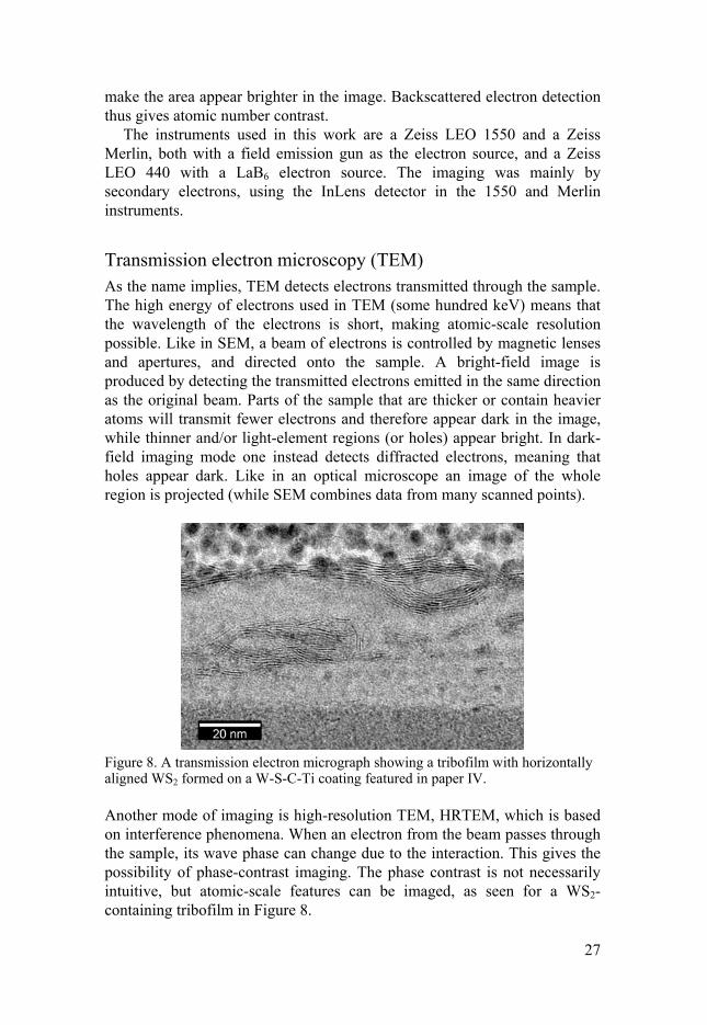
Transmission electron microscopy (TEM) As the name implies, TEM detects electrons transmitted through the sample. The high energy of electrons used in TEM (some hundred keV) means that the wavelength of the electrons is short, making atomic-scale resolution possible. Like in SEM, a beam of electrons is controlled by magnetic lenses and apertures, and directed onto the sample. A bright-field image is produced by detecting the transmitted electrons emitted in the same direction as the original beam. Parts of the sample that are thicker or contain heavier atoms will transmit fewer electrons and therefore appear dark in the image, while thinner and/or light-element regions (or holes) appear bright. In dark-field imaging mode one instead detects diffracted electrons, meaning that holes appear dark. Like in an optical microscope an image of the whole region is projected (while SEM combines data from many scanned points).
Figure 8. A transmission electron micrograph showing a tribofilm with horizontally aligned WS2 formed on a W-S-C-Ti coating featured in paper IV.
Another mode of imaging is high-resolution TEM, HRTEM, which is based on interference phenomena. When an electron from the beam passes through the sample, its wave phase can change due to the interaction. This gives the possibility of phase-contrast imaging. The phase contrast is not necessarily intuitive, but atomic-scale features can be imaged, as seen for a WS2-containing tribofilm in Figure 8.

28
Yet another imaging mode is scanning TEM, STEM. As the name implies, the electron beam is then scanned over the sample surface, and the signals from different points is combined into an image. STEM can be combined with other analysis techniques, such as EELS.
The TEM used in this work is a FEI Tecnai F30 with a FEG electron source. Diffraction and spectroscopic techniques, which may also be used in TEM, are described in the corresponding sections.
Focused ion beam (FIB) for sample preparation Since TEM samples must be very thin, extensive sample preparation is often needed. Using a focused ion beam (FIB) fitted in a SEM, a sample can be prepared from a specific part of the sample, for example a tribofilm. To fabricate a cross-section sample, a protective layer of for example Pt is first deposited onto the chosen part of the sample. The ion beam is used to mill trenches around the intended sample to make it thin and, finally, free-standing, so that it can be lifted out and attached to a sample holder. The thickness of the sample typically needs to be around 100 nm or less in order to be electron transparent, and a FIB-prepared sample is usually a few tens of µm wide. A sample prepared in this work is shown in Figure 9.
The equipment used for sample preparation in this work is a FEI Strata SEM equipped with a FIB.
Figure 9. A cross-section TEM sample during FIB preparation, imaged with the ion beam before lift-out (left) and with the electron beam during final polishing (right). The sample is taken from the wear mark on a W-coated ball run against a Ti-C-S coating in the work presented in paper VI.
Atomic force microscopy (AFM) AFM is a type of scanning probe microscopy which, as the name implies, images a surface by scanning it with a probe. A topographical image of the surface is then obtained, with atomic-scale resolution. The central part of an AFM is a cantilever with a very fine tip. When the tip is brought close to the sample surface, forces between them lead to deflection of the tip, which is detected while scanning across the surface and used to create an image.
The instrument used in this work is a PSIA XE150.

29
Diffraction The phenomenon of diffraction occurs for all sorts of waves when they meet obstacles, and means that the waves are spread out. If this occurs in several points, the diffracted waves can be enhanced or extinguished. By studying the diffracted waves, information about the obstacles (atoms), or more precisely about their relative positions (the structure), can be derived.
X-ray diffraction (XRD) XRD uses X-rays, most commonly Cu Kα radiation with a wavelength of 1.5406 Å, to study the structure of materials. The X-rays are diffracted by interactions with the electrons of the atoms in the material. For a crystalline material, the atoms are arranged with a long range order described by a lattice, and when the lattice plane spacing matches a whole number of wavelengths, positive interference occurs. The so-called Bragg’s law describes the relationship between plane spacing d, the wavelength λ, and the angle θ between the incoming X-rays and the planes.81
= 2
Thereby, the plane spacings can be calculated from the angles corresponding to high intensity, i.e. the positions of the peaks in the diffractogram. Different symmetries in the crystals will cause different reflections to be extinguished, and so the structure can be determined.
Additional information can be obtained from features in the diffractograms such as the peak broadening, as exemplified for Ti-C-S coatings in Figure 10. The fact that the crystals are not infinite in size leads to broadening, and increasingly so with decreasing crystallite size. The crystallite size can be estimated from the peak width, for example by the Scherrer equation: = 0.94cos
in which B is the full width at half maximum (FWHM) for a peak at an angle of θ originating from crystallites of size D, using radiation with a wavelength of λ.81 The equation assumes the crystallites to be equiaxial, i.e. the same size in all directions. However, grains in coatings are often elongated in some direction, which may be a source of error when using the Scherrer equation. Furthermore, most samples have a distribution of crystallite sizes, and the measurement will probe the average in the analysis volume.
The peak shapes and positions are also affected by strain in the sample. The width of the peaks can thus be an effect of both crystallite size and strain, and to separate the two, a Williamson-Hall plot can be used.82

30
However, if the coating is anisotropic with for example columnar crystals, or if the strain varies throughout the coating, the use of such plots is problematic.
The standard XRD measurement is a so-called locked-couple, or θ-2θ, measurement. The incidence angle and the exit angle are then changed simultaneously, meaning that only reflections from lattice planes parallel to the surface are measured. Unlike powders, coatings usually do not contain grains with random orientations, so all reflections may not be observed. While it may be disadvantageous not to observe reflections from some of the planes, this gives useful information on the texture, i.e. the orientation of the crystallites in the coating.
Figure 10. X-ray diffractograms for a series of Ti-C-(S) coatings. With increasing S content, the cubic TiCxSy phase experiences expansion in lattice parameter, manifested by a peak shift, and decrease in crystallite size, reflected by peak broadening.
For thin coatings, a measurement mode called grazing incidence XRD (GI-XRD) is often used increase the signals from the coating. In this mode, the incidence angle is kept small and constant (often 1-3°), and only the detector is scanned. The information depth changes with the incidence angle, as seen in Figure 11.
Many of the coatings in this work have a rather limited crystallinity, and some are even X-ray amorphous. There is then no long-range but only short-range ordering, and the resulting diffractogram does not feature any peaks but only a broad bump at low angles.
The XRD measurements in the current work have mainly been carried out on Siemens D5000 instruments, with either a focusing geometry for θ-2θ measurements, or a parallel-beam setup for GI measurements. In some cases, a Philips MRD instrument with a more flexible setup has been used. All instruments use Cu Kα radiation.

31
Figure 11. Information depth (above) and scanning process (below) for different XRD setups. In a θ-2θ scan, the incoming and outgoing angles are varied simultaneously, while the incoming angle is constant in a grazing incidence scan.
Electron diffraction in TEM Given the wave nature of electrons, they too can be diffracted, and electron diffraction is an important analysis mode in TEM. When using TEM for imaging, the electrons scattered in the same point of the sample are collected in the same point on the screen. The instrument can also be adjusted to collect all electrons scattered in the same direction in the same point, creating a diffraction pattern. This is an image of the reciprocal lattice of the sample, and each reflection represents a set of crystal planes, in the same manner as the peaks in an X-ray diffraction pattern. For a polycrystalline sample, the diffraction pattern can be seen as several patterns with different relative rotations, leading to the appearance of diffraction rings. Amorphous samples give only diffuse rings.
To study the diffraction from a specific part of the sample, apertures can be used in a technique called selected area electron diffraction (SAED). Furthermore, the inverse Fourier transform of a micrograph, or a selected part of it, can be used to obtain something like an artificial electron diffraction pattern.
Spectroscopy In spectroscopic methods, the interaction between radiation and a substance is studied. A spectrum, displaying the intensity or other response as a function of energy, is often used to represent the results.

32
X-ray photoelectron spectroscopy (XPS) When a material is irradiated by X-rays, electrons can be ejected, which are then called photoelectrons. The effect is known as the photoelectric effect. By knowing the energy of the X-ray photons (hν) and measuring the kinetic energy of the photoelectrons (Ek), and the work function (Φ) which is a constant for the specific instrument, the energy needed to remove the electrons (binding energy, Eb) can be calculated. The basic equation can be written as:
= ℎ − ( + ) The output of an XPS measurement is a spectrum with intensity as a function of energy, generally Eb, as illustrated in Figure 12. The peak positions in the spectrum correspond to energy levels in the sample atoms. Hence the elemental composition of the sample can be determined. However, different core levels in different atoms have different cross-sections, so for quantification one must correct for this using so-called sensitivity factors.
Figure 12. Upper left: The basic principle of XPS, with an incoming photon causing the ejection of a photoelectron. Lower: An XPS spectrum measured for a Ti-C-S coating. Upper right panel: A high-resolution C 1s spectrum for a Ti-C-S coating, with a line shape composed of contributions from C atoms in carbide grains (lower Eb) and C atoms in a carbon matrix (higher Eb).
The binding energy of an electron is affected by the chemical bonds of the atom, resulting in a so-called chemical shift. However, the contributions

33
from atoms in different chemical states are not always well separated, meaning that one peak shape is measured for several states. A way to separate the contributions is to perform a curve fit.83 The outcome of such a fitting operation is heavily dependent on the input and the restrictions applied.
With standard Al Kα radiation, the mean free path is a few nm, meaning that the analysis volume is only the outermost surface of the sample. In many cases, the surface is oxidized by contact with ambient atmosphere, and various molecules are adsorbed on the surface. To measure the actual material of interest, it is therefore necessary to remove the outermost layers, which is commonly done by sputter etching with Ar+ ions in the analysis chamber prior to measurements.
However, sputter etching may induce changes in the remaining material. For WS2 and MoS2, it is a known problem that the light and volatile S is preferentially sputtered, meaning that the composition and the chemical bonding of the remaining material is changed even when using low-energy ions.28, 29, 31 Paper I is devoted to studying this phenomenon for W-S coatings. For TiC/a-C coatings, it has been shown that sputter etching changes the chemical states.84
The instrument used for all in-house XPS measurements is a PHI Quantum 2000, with Al Kα radiation (1487.6 eV). It is equipped with an Ar+ ion gun for sputter etching, which can be performed using ion energies from 200 eV to 4 keV. Curve fitting has been performed using CasaXPS software.
Hard X-ray photoelectron spectroscopy (HAXPES) As previously described, the probing depth is dependent on Ek, and thus on the photon energy hν. By using photons of higher energy, the probing depth can thus be increased.85 Photons of higher energy than from Al or Mg anodes can be obtained from a synchrotron light source, which also has the benefit of a tunable photon energy.
The higher energies used in HAXPES also make it possible to measure at higher Eb, accessing deeper core levels. One example of importance in this work is found for W, for which the W 4f region is normally analyzed. However, the separation between the W 4f7/2, W 4f5/2 and W 5p3/2 lines is small, which makes the interpretation difficult. With synchrotron radiation, it is also possible to measure the W 3d5/2 line, which is extremely well separated from the W 3d3/2 line. In paper I, HAXPES was employed to study W-S coatings, to elucidate the chemical bonds of undisturbed material, and to study the effects of sputter damage.
Paper I is based on measurements performed at the HIKE experimental station at the KMC-1 beamline at the BESSY II synchrotron facility of the Helmholtz-Zentrum Berlin, Germany.85-87

34
X-ray absorption spectroscopy (XAS) XAS is used to study the local atomic arrangements in a sample. The energy range for the X-rays photons is chosen to match the excitation energy of core electrons in the sample, and the absorption coefficient is measured as a function of the energy. The absorption edges in the spectrum are characteristic for the element in question. Above an absorption edge, oscillations in the spectrum occur due to interference between outgoing photoelectrons, and photoelectrons backscattered from neighboring atoms. These oscillations give information about the local environment of the excited atom, regarding the bond distances (reflected by the frequency) and the type and number of the surrounding atoms (reflected by the amplitude).
The method for studying an extended energy range beyond the absorption edge is referred to as EXAFS, extended X-ray absorption fine-structure. In this work, EXAFS was used for amorphous W-S-N coatings (paper II), to study the coordination shells of sample atoms, and the results were compared to those of theoretical calculations. When studying the energy immediately around the edge to obtain information about chemical bonding, the terms NEXAFS (near edge X-ray absorption fine structure) and XANES (X-ray absorption near edge structure) are used.
The radiation used in XAS is soft X-rays, but because of the need for tunable photon energies and high intensities, the experiments are performed at synchrotron facilities. Measurements in this work were performed at the MRCAT beamline of the Advanced Photon Source at Argonne National Laboratory in Illinois, USA and at the SuriCat endstation of beamline PM3 at the BESSY II synchrotron light source of Helmholtz-Zentrum in Berlin, Germany.
Energy-dispersive X-ray spectroscopy (EDS) EDS (also abbreviated EDX) is a technique for elemental analysis, often used in combination with SEM or STEM. It relies on the emission of characteristic X-rays from a sample when its atoms are excited by, for example, an electron beam. The interactions with incoming electrons can lead to the ejection of electrons from the sample, creating electron holes. The hole can then be filled by an electron from a higher energy level in the atom, with the energy difference released in the form of an X-ray. The X-ray energy is characteristic for the particular transition, and thus for the element. By performing measurements at different points on the sample, maps of the elemental composition over a surface can be determined.
In this work, EDS measurements have been performed using the Zeiss instruments also used for SEM.

35
Electron energy-loss spectroscopy (EELS) As the name implies, EELS studies the energy loss from electrons as they interact with a sample. It is often used in a TEM, where the kinetic energies of electrons transmitted through the sample are measured. The energy loss then corresponds to the energy needed for ionization of a sample atom byt removal of a core level electron. The technique has similarities to XPS, and the peaks are subject to chemical shifts.
EELS can be used in combination with STEM to obtain elemental maps. Furthermore, one can filter the transmitted electrons so that only those with a specific energy are used for imaging, in a technique befittingly called EFTEM (energy filtered TEM).
Raman spectroscopy In Raman spectroscopy, materials are studied by their interactions with monochromatic light, usually in or close to the visible energy range. The interactions are for example vibrations or rotations, and the technique thus probes compounds rather than elements.
The Raman effect is a form of light scattering, in which a photon excites a molecule or compound to a virtual energy state. The material then relaxes to an excited state, and the energy difference between the virtual and the excited state is released as a photon. The energy difference compared to the incoming photons is called the Raman shift, which is usually expressed in wavenumbers, using the unit cm-1.
For molecules, the excited states are vibrational or rotational states. In a crystal, there are collective vibrations, which are often described as phonons. Only vibrations, or phonons, which change the polarizability will interact with the photons. It is important to note that not all substances are Raman active, and that the intensity of the Raman signals is different for different bonds, so Raman spectroscopy is not suitable for direct quantification. However, the spectra are useful for identification of Raman-active phases, and disorder and loss of crystallinity is associated with peak broadening.
In this work, Raman spectroscopy has been used to study as-deposited coatings as well as wear tracks and wear marks. The typical mode of measurement is so-called micro-Raman spectroscopy, where the lateral size of the measurement spot is a few to a few tens of micrometers. It is also possible to measure Raman spectra from a large number of points on a sample, producing maps of the occurrence of specific components.
The instruments used in this work are a Renishaw micro-Raman system with a 514 nm laser, and a Renishaw inVia microscope, in which a 532 nm laser was used. The inVia microscope was used for Raman mapping by so-called StreamLine imaging. Curve fits were then performed in MATLAB®.

36
Other characterization techniques X-ray reflectivity (XRR) X-ray reflectivity is performed in the same equipment as XRD, in a setup similar to a θ-2θ measurement, but it is not based on diffraction. For very narrow incoming angles of the beam, the x-rays are totally reflected. For a coating, the beam is reflected by two interfaces: air/coating and coating/substrate. This results in two reflected beams with a path difference, and the interference causes fringes in the recorded scan. The fringe separation is related to the coating thickness, while the onset of the intensity decrease is related to the coating density.81 The density and thickness are obtained by fitting a simulated curve to the measured one, using estimates of the composition and density as input.
In this work, XRR was used to estimate the density of amorphous W-S-N coatings from measurements on a Siemens D5000 with Cu Kα radiation.
Nanoindentation Nanoindentation is a technique for measuring the hardness of a small volume of material. Like in traditional indentation tests, a hard tip is pressed into a sample, and the relation between the applied load and the penetration is a measure of the hardness.
In macro- and microindentation, such as a Vickers, Brinell, Knoop or Rockwell hardness test, the size of the indent is measured by visual inspection after the test (often using a microscope). In nanoindentation, or instrumented indentation, the penetration depth is instead recorded during the indentation. By using a tip of well-defined geometry, the indent area can be calculated from the depth. Nanoindentation is typically performed with a Berkovich tip, a three-sided diamond pyramid with a half angle of 65.35°, giving it the same ratio between the (projected) area and the depth as a Vickers indenter.
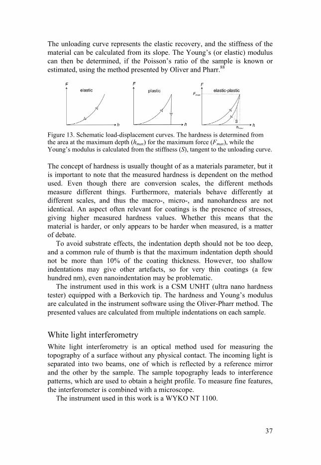
The result of a nanoindentation measurement is often displayed as a load-displacement curve, as shown in Figure 13. For a material with a purely elastic behavior, the load and unloading curves would be identical. If it was purely plastic, the unloading curve would not show any displacement. Most materials are, however, both plastically and elastically deformed. The loading curve then displays the plastic and elastic deformation, and the unloading curve the elastic recovery. The measured hardness is calculated from the maximum applied load (Fmax), and the projected area (Ap): =
37
The unloading curve represents the elastic recovery, and the stiffness of the material can be calculated from its slope. The Young’s (or elastic) modulus can then be determined, if the Poisson’s ratio of the sample is known or estimated, using the method presented by Oliver and Pharr.88
Figure 13. Schematic load-displacement curves. The hardness is determined from the area at the maximum depth (hmax) for the maximum force (Fmax), while the Young’s modulus is calculated from the stiffness (S), tangent to the unloading curve.
The concept of hardness is usually thought of as a materials parameter, but it is important to note that the measured hardness is dependent on the method used. Even though there are conversion scales, the different methods measure different things. Furthermore, materials behave differently at different scales, and thus the macro-, micro-, and nanohardness are not identical. An aspect often relevant for coatings is the presence of stresses, giving higher measured hardness values. Whether this means that the material is harder, or only appears to be harder when measured, is a matter of debate.
To avoid substrate effects, the indentation depth should not be too deep, and a common rule of thumb is that the maximum indentation depth should not be more than 10% of the coating thickness. However, too shallow indentations may give other artefacts, so for very thin coatings (a few hundred nm), even nanoindentation may be problematic.
The instrument used in this work is a CSM UNHT (ultra nano hardness tester) equipped with a Berkovich tip. The hardness and Young’s modulus are calculated in the instrument software using the Oliver-Pharr method. The presented values are calculated from multiple indentations on each sample.
White light interferometry White light interferometry is an optical method used for measuring the topography of a surface without any physical contact. The incoming light is separated into two beams, one of which is reflected by a reference mirror and the other by the sample. The sample topography leads to interference patterns, which are used to obtain a height profile. To measure fine features, the interferometer is combined with a microscope.
The instrument used in this work is a WYKO NT 1100.

38
Electrical resistivity measurements The electrical properties of a coating can be assessed by the four-point probe method, which measures the resistance of the material. It uses two pairs of probes, to distinguish between the voltage drop across the tested material and the voltage drop in the probes themselves. The method gives the sheet resistance of the coating, which can be used to calculate the resistivity of the material if the thickness is known.
In this work, a CMT-SR2000N instrument from Advanced Instrument Technology was used to characterize the electrical properties of W-S-N.
Tribological evaluation The tribological contact in for example a motor is complex with many interplaying parameters. The behavior of a material in its desired application should thus be best studied in a setting as real as possible. However, tests of components in real operation are expensive and complicated, and it would be impossible to study the effect of individual parameters. Model setups are suitable for early-stage development, and to study fundamental aspects, as they offer good control of parameters such as load, speed, contact geometry and environment. In this work, test rigs with a so-called ball-on-disc configuration have been used. The coating is then deposited on a flat substrate, and run against a counter-surface in the shape of a ball.
For tribological testing, the coatings have been deposited on tool steel substrates, mostly high-speed steel (PMHS 6-5-3C) but another steel (X153CrMoV12) was used for the W-S-N coatings. The substrates were mirror-polished (Ra ≈ 10 nm), and ultrasonically cleaned in acetone and ethanol. Prior to deposition they were ion etched in the deposition chamber and, when possible, an interlayer of Ti was deposited for increased adhesion. Ball bearing steel balls were typically used as the sliding partner, although other ball materials were used to study the tribochemistry of Ti-C-S coatings.
Figure 14. Ball-on-disc setups with rotating (left) and reciprocating (right) geometry.

39
Two different setups were used for testing, one with a rotating geometry, and one with a reciprocating geometry, as illustrated in Figure 14. In both cases, the flat, coated sample is attached to a moving sample table. The ball is attached to a stationary pin, and positioned on top of the coated sample. A normal load FN is applied on the ball. In rotating geometry the sample rotates to create a circular wear track, while in reciprocating geometry the sample moves back and forth, creating a straight wear track with two ends. During sliding, the ball experiences a friction force FF, which is measured on the ball holder by a load cell, and the friction coefficient is then calculated as the ratio between FF and FN.
Parameters such as load, speed, and radius/stroke can be varied. Furthermore, the atmosphere can be controlled by the covering the setup with a hood. Dry air, N2, and water vapor can then be flowed through the setup, and the relative humidity can be controlled.
While the friction coefficient is measured continuously during the test, wear is estimated from the wear track afterwards. Profiles of the wear tracks were measured using white light interferometry, giving a cross-sectional area of the track, from which the worn volume can be calculated, and used to calculate the specific wear rate. In this work, the area has usually been truncated at the level of the unworn coating, so that any pile-up on the side of the track does not give a negative contribution.

40
Theoretical methods
The information from analytical techniques, as described in the previous section, is generally the sum of states in the analysis volume, which contains a great number of atoms. Theoretical calculations are then a powerful tool to study materials on the atomic level.
To describe a material as a collection of atoms interacting according to the established laws of nature, without any other assumptions or input, is called a first principles or ab initio calculation. When describing a material on the atomic level, as nuclei with electrons, a large number of interacting particles must be included – this is the so-called many-body problem. It is not possible to make an exact description, i.e. solve the Schrödinger equation, for such a system, and various approximations and limitations are needed. One such is the Born-Oppenheimer approximation, which allows for separation of the nuclear and the electronic interactions.89 Because of the large difference in mass between nuclei and electrons, the electrons move much faster than the nuclei, and the electronic movements can be described without considering changes in the positions of the nuclei. However, the number of electrons is still too large for a numerical calculation. One way to handle this is described by density functional theory (DFT), formulated by Hohenberg and Kohn.90 Interacting electrons and nuclei are then replaced by non-interacting electrons in an effective potential. The effective potential, i.e. the combined effect of nuclei and electrons, is a functional of the total charge density, hence the name of the method.
A problem in DFT calculations is that the exact functionals for the exchange and correlation parts of energy are not known, so the exchange-correlation term must be approximated. The generalized gradient approximation, which includes the gradient (i.e. the first derivative) of the density, has been employed in this work, using the functional described by Perdew, Burke and Ernzerhof.91
One way to increase the efficiency of DFT calculations is to use the projector augmented wave method.92 Close to the nucleus, the wave functions oscillate rapidly, which would require a detailed description. This can be simplified by transforming them into smooth wavefunctions. The calculations in this work are performed using this method as implemented in the Vienna ab initio simulation package (VASP).93
Many solids are crystalline, and can thus be described by a repeating pattern. In a simple approximation, the effective potential can be viewed as

41
spherical potentials around the periodically placed nuclei, with a constant potential between the spheres. Illustratively, this is called the muffin-tin approximation. An improved version is found in the exact muffin-tin orbitals (EMTO) method, which has been used in this work. The spheres (or muffin-tin wells) are then large and overlapping, which is a better representation of the potential on the crystal, and single electron equations are solved for an optimized overlapping muffin-tin potential.94
An important aspect and challenge is, however, that real materials always contain defects and disorder, such as grain boundaries, stacking faults, vacancies and impurities. EMTO needs to be combined with other methods for dealing with disordered systems. For substitutionally disordered materials, one could imagine all atoms as identical, with each atom being a concentration-weighted average of all atoms in the system. A more refined approach is to use the average system (effective medium) as a matrix, in which a single impurity is placed. This is called the coherent potential approximation (CPA), and was initially introduced to describe, for example, random alloys.95 It can be combined with EMTO theory, in the EMTO-CPA method,94 which was one of the methods used in paper VI to model TiCxSy, a titanium carbide where part of the C atoms are replaced by S atoms.
A possible weakness of the EMTO-CPA method is that the local structure is not accounted for. Another approach is then to place the different atoms on lattice positions in a so-called supercell. The cells have periodic boundary conditions, so that one simulates a material of repeating supercells. Supercells were used to model the TiCxSy phase in paper VI by special quasirandom structures, which can be used to model substitutional solid solutions. In such structures, the lattice sites are selectively occupied by the two different atoms (in this case C and S) to mimic the local atomic structure of a random alloy.96 The average of such a structure thus corresponds to the random alloy, while locally the atoms have specific atoms as neighbors.
Substitutional disorder in a crystalline system can thus be accomodated within the approaches described above. For amorphous systems, however, the situation is different, since the atomic positions cannot be described by a periodical lattice. One method is to perform the equivalent of melting and rapidly cooling the material. The simulation of the movements of interacting atoms at finite temperature is called molecular dynamics (MD). To start the simulation, the atoms are placed at initial positions, and the forces on them are calculated. The atoms are then allowed to move according to the forces, and the time is moved forward. The alternating force calculations and movements are then looped. More steps for control of various parameters can be included in the loop, and different constraints can be applied. For example, when using a so-called canonical ensemble the temperature, volume and number of atoms is kept constant. The temperature is controlled with a thermostat, a method which can add or remove energy from the system. In paper II, an amorphous W-S-N system was simulated as randomly

42
distributed atoms which were melted and equilibrated at a high temperature, and cooled, using the Andersen thermostat.97 This thermostat changes the temperature of the system by having its atoms/molecules randomly colliding with an imaginary heat bath. The times between collisions of randomly selected atoms come from a distribution of the stochastic collision frequency.
A variety of information can be deducted from a simulated system. First of all, the atomic arrangements can be studied. For a crystalline system, the lattice parameter can be interesting, for example for TiCxSy in paper VI. In amorphous W-S-N, atomic arrangements such as coordination numbers and bond distances are highly interesting. The atomic configurations are characterized by the radial distribution functions (RDFs) for different atomic pairs, showing the nearest neighbor distances. EXAFS spectra were also simulated for the calculated structures, for comparison with the experimental results. Furthermore, atomic structures and charge distributions (shown by isosurfaces) can be visualized. The atomic charges can be used to determine the charge transfer, and thus the ionic character of a bond.
Figure 15. Electronic DOS calculated for TiC (left) and TiC0.5S0.5 (right). The vertical line indicates the Fermi level, EF. Adapted from paper VI.
The electronic properties of the simulated material can also be described by the density of states of the system. In isolated atoms or molecules, the energy levels are discrete, but in a solid containing a large number of atoms the energy levels form more or less continuous bands – a band structure. The number of states available at each energy level is described as the density of states, DOS, as shown in Figure 15. The so-called Fermi level is the crossover between the levels which are occupied (in ground state), and those that are not. The location of the Fermi level in the bands is important for the electrical properties of the material. For insulators, it lies within a band gap, and for metallic materials it lies within a band. The total DOS is the sum of the partial DOS, from different orbitals in different atoms. By studying the contributions to the total DOS, information about the chemical bonding can be deduced. For example, it is possible to see which orbitals hybridize to form bonds.

43
Results
The work in this thesis has been aimed at developing and studying potential materials for inorganic low-friction coatings. More specifically, the goal is to develop an understanding of the relation between the composition and structure of the coating materials, and their mechanical properties and tribological performance. The project is focused on triboactive materials, meaning that they actively change in a tribological contact. The study of processes occurring in a tribological contact, such as the formation of tribofilms, has therefore been an important question.
Different materials systems, based on WS2 and/or TiC, have been studied by producing series of coatings with varying compositions and microstructures, and tribologically testing them, possibly with different atmospheres or counter-surfaces. Theoretical simulations of some materials have been employed to gain a thorough understanding of the atomic arrangements.
Throughout this work, denotations like W-S-N or Ti-C-S are used for a materials system and for the coating material as a whole, while denotations like WSx and TiCxSy are used for chemical phases that make up all or part of the material.
WS2-based materials A large part of the current work has been focused on WS2-based materials, namely the materials systems W-S-N, W-S-C and W-S-C-Ti. Coatings without additive elements, i.e. W-S, have been studied along with the ternary and quaternary coatings in papers II-V, and were the main focus of paper I.
W-S The structure of W-S coatings varies with the deposition conditions, such as the temperature. Samples for which the substrate was heated to approximately 300ºC during deposition are denoted HT (high temperature). They were found to be porous, with a columnar morphology, and in some cases very distinct flakes (see Figure 2 on p. 13). To the bare eye, these coatings have a black and velvet-like appearance, and they are easily scratched by virtually anything, due to the poor adhesion of the standing

44
flakes. Coatings deposited at room temperature (RT) have a dense morphology, sometimes almost featureless. They are grey and shiny, and withstand handling without noticeable scratching. The dense RT coatings have a hardness of a few GPa, like many ternary and quaternary WS2-based coatings. HT coatings have a much lower measured hardness, due to the extremely easy relocation of the standing flakes.
X-ray diffractograms for the two coatings studied in paper I (and IV) are shown in Figure 16. The diffraction pattern of the HT coating is typical for sputtered WS2, with the two peaks indexed as (10l) and (11l) as the main features. Due to the weak interactions between the sandwich layers in WS2, there may be some rotational and/or translational disorder around the c axis, a phenomenon called turbostratic stacking.6, 21, 27 In GI-XRD, this leads to the appearance of asymmetric composite peaks, instead of discrete reflections for different values of l. For measurements in θ-2θ setup, only planes parallel to the surface are detected, and the absence of asymmetric tails indicate that only (hkl) planes with l = 0 meet this criterion, meaning that the basal planes are perpendicular to the surface.27 However, a small (002) reflection is also observed in θ-2θ measurements. This is likely to originate from a nucleation layer with basal planes parallel to the surface,35 which is not observed in GI-XRD where the information depth is smaller.
Figure 16. X-ray diffractograms for the two W-S coatings in paper I.
The RT coatings give broad features at same peak positions, and thus consist of even smaller clusters with limited long-range order. The difference in crystallinity between HT and RT coatings can be connected to the increased possibilities for the atoms to diffuse on arrival to the substrate, when the substrate is heated. The W-S coatings from the W-S-N and W-S-C-(Ti) series are all substoichiometric in S, with a S/W ratio of 1.0 to 1.3. X-ray photoelectron spectra showed a minor contribution of W-W bonds for the RT coating in paper I, but otherwise no signs of a W phase are observed, and the coatings can therefore be considered to consist of a WSx phase with x < 2. Coatings sputtered from WS2 targets are often substoichiometric with

45
respect to sulfur,21, 23 as was the case for all WS2-based coatings deposited within the project, with the exception of some coatings deposited by reactive sputtering from a WS2 target and H2S(g). Due to the difference in mass between W and S, the latter are to a larger degree scattered in the gas phase, and not reaching the substrate.24
When studying the composition and chemical bonding by XPS, the surface sensitivity of the technique means that a large part of the measured signal originates from oxidized or contaminated material on the outermost surface. The standard method for cleaning the surface is sputter etching with Ar+ ions. However, it is well-known that bulk crystals of WS2 and MoS2 are prone to sputter damage, with the ion bombardment leading to a depletion of S.28-31 In paper I, this phenomenon was investigated for W-S coatings, using HAXPES to study the undisturbed coating material as well as the effects of sputter damage by measurements with different Ek (to obtain different probing depths), before and after sputter etching.
The as-deposited W-S coatings, beneath the outermost oxidized surface, consist of a substoichiometric WSx phase, with no indications of other phases. The WSx phase should thus be WS2 with some S atoms lacking, and it is indeed known that sputtered WSx and MoSx coatings can retain this structure even when they are severely substoichiometric.21, 22 Thermodynamically, the homogeneity range of WS2 (and MoS2) is narrow, and the material should consist of a WS2 and a W phase,26 but the non-equilibrium conditions during sputter deposition limit the diffusion of the atoms, resulting in a S-deficient WSx phase. In HAXPES measurements the WSx contributions in the W and S spectral regions are much broader than those measured for a single crystal WS2 reference sample under the same conditions, suggesting that there is more variation in the bonding environment of the atoms, i.e. that the S vacancies are not ordered.
The larger probing depth of HAXPES allows studying the as-deposited material beneath the outermost surface. Still, WO3 contributions dominate the spectra of the as-deposited coatings. With sputter etching, the WO3 contribution decreases, and contributions from WSx and W became more prominent, as seen in Figure 17. The contribution from metallic W increased more with sputter etching time than that from WSx, and was more prominent in the 3 keV spectra. All these observations show that sputter etching leads to the formation of a metallic W phase, which is not present in the original material. The WSx contribution in the S spectral regions did not change much on sputter etching, except for a slight broadening. The S remaining after sputter-etching is thus found in a similar chemical bonding environment as in the as-deposited coatings. Sputter damage thus leads to the formation of a purely metallic W phase rather than the formation of a gradually more substoichiometric WSx phase. This is in line with previous studies of bulk WS2 and MoS2 crystals.28, 29, 98

46
In standard XPS (with lower Ek), spectra from as-deposited coatings show mainly WO3, while spectra measured after sputter cleaning show sputter-damaged material. The effect of the sputter damage should be the same for the WSx phase in other WS2-based coatings, and metallic W has indeed been observed in the spectra from sputter-etched W-S-N, W-S-C and W-S-C-Ti in this work. In for example W-S-C coatings, the interpretation is complicated by the fact that the binding energies for W-W and W-C bonds are similar. It is thus difficult to determine how much of the low-Eb contribution that originates from a (possible) WCx phase, and how much is the result of sputter damage. These findings are important for the XPS analysis of all kinds of WS2-based coatings, as the spectra are easily misinterpreted if this aspect is not considered.
Figure 17. Spectra measured by HAXPES for a W-S coating after 0, 20 and 60 min of sputter-etching, with Ek of 3 or 6 keV (adapted from paper I).
W-S-N In many cases, sputtered W-S coatings are porous and soft, and one may not obtain the benefits of having the material as a coating, if the coating cannot
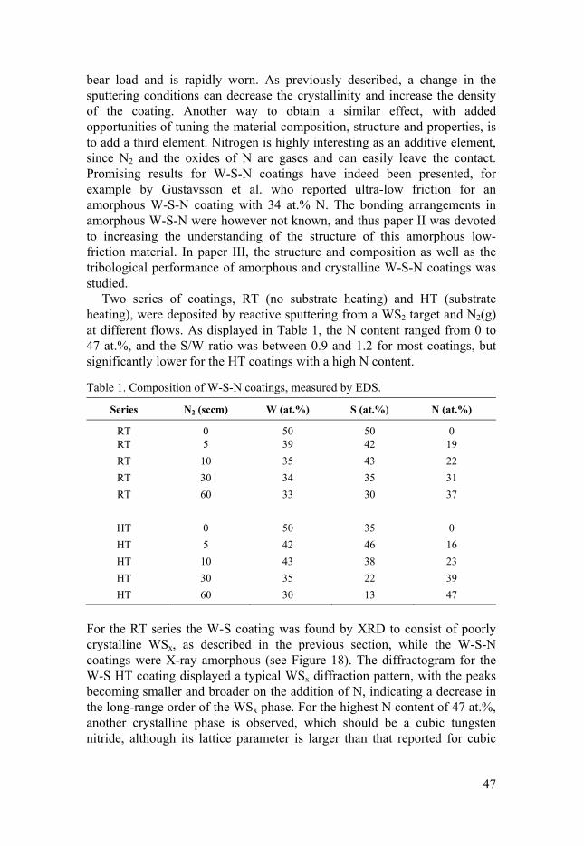
47
bear load and is rapidly worn. As previously described, a change in the sputtering conditions can decrease the crystallinity and increase the density of the coating. Another way to obtain a similar effect, with added opportunities of tuning the material composition, structure and properties, is to add a third element. Nitrogen is highly interesting as an additive element, since N2 and the oxides of N are gases and can easily leave the contact. Promising results for W-S-N coatings have indeed been presented, for example by Gustavsson et al. who reported ultra-low friction for an amorphous W-S-N coating with 34 at.% N. The bonding arrangements in amorphous W-S-N were however not known, and thus paper II was devoted to increasing the understanding of the structure of this amorphous low-friction material. In paper III, the structure and composition as well as the tribological performance of amorphous and crystalline W-S-N coatings was studied.
Two series of coatings, RT (no substrate heating) and HT (substrate heating), were deposited by reactive sputtering from a WS2 target and N2(g) at different flows. As displayed in Table 1, the N content ranged from 0 to 47 at.%, and the S/W ratio was between 0.9 and 1.2 for most coatings, but significantly lower for the HT coatings with a high N content.
Table 1. Composition of W-S-N coatings, measured by EDS.
Series N2 (sccm) W (at.%) S (at.%) N (at.%)
RT 0 50 50 0 RT 5 39 42 19
RT 10 35 43 22
RT 30 34 35 31
RT 60 33 30 37
HT 0 50 35 0
HT 5 42 46 16
HT 10 43 38 23
HT 30 35 22 39
HT 60 30 13 47
For the RT series the W-S coating was found by XRD to consist of poorly crystalline WSx, as described in the previous section, while the W-S-N coatings were X-ray amorphous (see Figure 18). The diffractogram for the W-S HT coating displayed a typical WSx diffraction pattern, with the peaks becoming smaller and broader on the addition of N, indicating a decrease in the long-range order of the WSx phase. For the highest N content of 47 at.%, another crystalline phase is observed, which should be a cubic tungsten nitride, although its lattice parameter is larger than that reported for cubic

48
W2N (see the dedicated section “The unknown tungsten nitride phase” on p. 51). Cross-section micrographs (Figure 19) show that both W-S coatings are porous, and the W-S HT has a characteristically flaky appearance. On addition of N, the RT coatings become dense and glass-like. For the HT coatings, a columnar morphology can be seen for all coatings, but for high N contents it is distinctly different from the sulfide, in agreement with the appearance of a crystalline nitride observed by XRD.
Figure 18. X-ray diffractograms for W-S-N coatings, with the N content (in at.%) indicated for each coating.
Figure 19. Scanning electron micrographs of fractured cross-sections of WSN coatings: a) RT 0, b) RT 10, c) RT 60, d) HT 0, e) HT 10, and f) HT 60.
This evolution of microstructure and structure is typical for sputter-deposited coatings when a third element is added to TMD. Even in a pure TMD coating, the diffusion of deposited atoms is limited, leading to a nanocrystalline material – more so if the temperature of the substrate is low. Co-deposition with some other element further limits the possibility of
49
forming ordered TMD domains. With increasing addition of N (or any other element), the WSx domains thus become smaller, eventually leading to an amorphous material. This change in microstructure is accompanied by an increased in density, compared to the more or less porous pure WSx, which also affects the mechanical properties. The W-S-N RT coatings, all being amorphous and dense, exhibited a hardness of about 4-5 GPa, while the W-S coating was slightly lower at 3 GPa. For the HT series, a clear increase in hardness was seen on increasing the N content, from difficult to measure for the porous, crystalline W-S coating, to 10 GPa for the coating with the highest N content containing a crystalline nitride.
Depending on the substrate temperature during deposition, the addition of N thus leads to amorphous W-S-N coatings of different content, or to the evolution from nanocrystalline sulfide (low N) to nanocrystalline nitride (high N). The chemical bonding conditions are, however, similar for the two series. For the W-S coatings, XPS spectra in the W 4f region feature a contribution from the WSx phase at a Eb of 32.5 eV. With increasing N content, the latter moves towards higher Eb, and becomes broader. Given that N is more electronegative than S, and that Eb around 33 eV have been reported for W-N compounds,99 this indicates an increasing proportion of W-N bonds. A shift from W-S bonds towards W-N bonds is consistent with the transition from sulfide to nitride observed by XRD for the HT series, and apparently the chemical bonding conditions are similar in the X-ray amorphous RT coatings. This is true also for S and N, which give similar spectra for both series. S 2p3/2 lines are found at a binding energy of 162.2 eV, matching that of WSx. With the addition of N, the intensity decreases and the peaks broaden. In the N 1s region, the main contribution is found around 397.0-397.5 eV, which can be ascribed to N-W bonds.100 However, there is also a smaller contribution at 400 eV, which is similar to values reported for N-N bonds.101 The presence of N2 species was confirmed by NEXAFS measurements of the RT 60 coating, showing a N 1s→π* resonance similar to that of gaseous N2.
Theoretical and experimental methods were combined to study the atomic coordination in amorphous W-S-N in detail. A material of approximately 1:1:1 composition (W0.33S0.33N0.34), similar to that of the RT 30 coating, was simulated by molecular dynamics, MD, and simulated EXAFS oscillations were compared to experimental data for the RT 30 coating. The W-S nearest neighbor (NN) distances from theory and experiment were found to be in excellent agreement, with 2.37-2.39 Å, but slightly shorter than the W-S bond distances of 2.41-2.48 Å reported in literature for 2H-WS2.
4, 102 Also for W-N atomic pairs, the theoretical and experimental NN distances are in good agreement (1.94-1.96 and 1.93 Å, respectively) but slightly shorter than in reference compounds such as WN (2.07-2.19 Å) and organometallic W-N2 complexes (1.97-1.99 Å).

50
For S-S and S-N atomic pairs, the average NN distances as determined from the RDFs were significantly longer than the bonds in reference compounds S8 and S3N4. However, the RDFs also contained additional peaks matching the bond lengths in these compounds, indicating the existence of some proper S-S and S-N bonds in the material. For N-N atomic pairs, the RDF curve displays a strong peak at approximately 1 Å, which is similar to the bond distance in a N2 molecule. Looking into the theoretical structures, they were found to contain 7-8 N2 molecules with atomic distances slightly larger than in gaseous N2, in good agreement with the observations of N-N bonds from XPS and NEXAFS, and analogous to O2 pairs observed in amorphous alumina and silica.103 The presence of N2 units has previously been reported for W-N coatings sputtered from W and N2(g).104 In the theoretical structure in paper II, the N2 molecules could be studied in more detail, and it was found that they cluster together in cages in the material. The bond distances between the N atoms in N2 and the S atoms lining the cage were fairly large, in the range of 2.8-4.2 Å, and there should thus not be strong chemical interactions between them. An S-lined cage containing 5 N2 molecules, from one of the theoretical structures, is shown in Figure 20.
Figure 20. A large cage, containing 5 N2 molecules surrounded by S atoms, in cross-section view (left) and side view (right). W, S and N atoms are shown in grey, yellow and cyan, respectively. (Adapted from paper II.)
Amorphous W-S-N can thus be described as an amorphous network, connected mainly by W-N and W-S bonds. No WSx layers are present in the material. However, the material contains some N2 units, which are often coordinated by (but seldom properly bonded to) S, and could be called quasi-free. It is interesting to note that experimental detection of N2 in coatings sputtered using N2(g) could be suspected to originate from molecules being trapped during deposition, but no N2 molecules are used as input for the
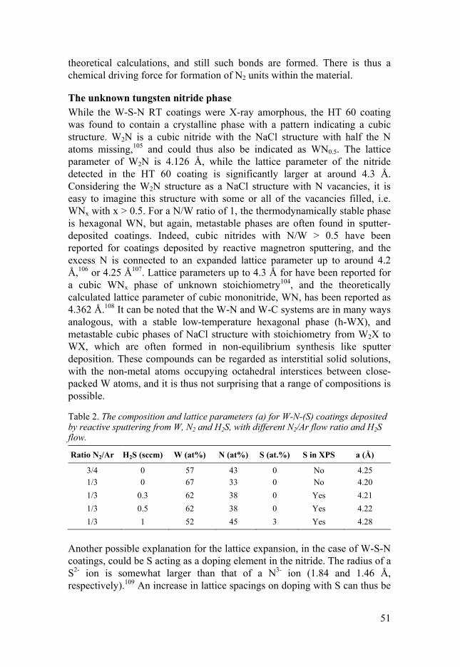
51
theoretical calculations, and still such bonds are formed. There is thus a chemical driving force for formation of N2 units within the material.
The unknown tungsten nitride phase While the W-S-N RT coatings were X-ray amorphous, the HT 60 coating was found to contain a crystalline phase with a pattern indicating a cubic structure. W2N is a cubic nitride with the NaCl structure with half the N atoms missing,105 and could thus also be indicated as WN0.5. The lattice parameter of W2N is 4.126 Å, while the lattice parameter of the nitride detected in the HT 60 coating is significantly larger at around 4.3 Å. Considering the W2N structure as a NaCl structure with N vacancies, it is easy to imagine this structure with some or all of the vacancies filled, i.e. WNx with x > 0.5. For a N/W ratio of 1, the thermodynamically stable phase is hexagonal WN, but again, metastable phases are often found in sputter-deposited coatings. Indeed, cubic nitrides with N/W > 0.5 have been reported for coatings deposited by reactive magnetron sputtering, and the excess N is connected to an expanded lattice parameter up to around 4.2 Å,106 or 4.25 Å107. Lattice parameters up to 4.3 Å for have been reported for a cubic WNx phase of unknown stoichiometry104, and the theoretically calculated lattice parameter of cubic mononitride, WN, has been reported as 4.362 Å.108 It can be noted that the W-N and W-C systems are in many ways analogous, with a stable low-temperature hexagonal phase (h-WX), and metastable cubic phases of NaCl structure with stoichiometry from W2X to WX, which are often formed in non-equilibrium synthesis like sputter deposition. These compounds can be regarded as interstitial solid solutions, with the non-metal atoms occupying octahedral interstices between close-packed W atoms, and it is thus not surprising that a range of compositions is possible.
Table 2. The composition and lattice parameters (a) for W-N-(S) coatings deposited by reactive sputtering from W, N2 and H2S, with different N2/Ar flow ratio and H2S flow.
Ratio N2/Ar H2S (sccm) W (at%) N (at%) S (at.%) S in XPS a (Å)
3/4 0 57 43 0 No 4.25 1/3 0 67 33 0 No 4.20
1/3 0.3 62 38 0 Yes 4.21
1/3 0.5 62 38 0 Yes 4.22
1/3 1 52 45 3 Yes 4.28
Another possible explanation for the lattice expansion, in the case of W-S-N coatings, could be S acting as a doping element in the nitride. The radius of a S2- ion is somewhat larger than that of a N3- ion (1.84 and 1.46 Å, respectively).109 An increase in lattice spacings on doping with S can thus be

52
imagined (to maintain a neutral total charge, W atoms could be present in several oxidation states, and/or there may be W vacancies).
To investigate the possibility of a S-doped nitride, a number of coatings were deposited reactively from a W target and N2(g), and for some coatings also H2S(g) (see Table 2). The composition was determined by EDS, but the S concentrations were very low (a few at.%), and were also checked by XPS. All three W-N-S coatings were found to contain S, although it was only detected by EDS for the one with the highest S content.
The X-ray diffraction patterns of all coatings showed a cubic phase, similar to the nitride in the W-S-N HT 60 coating but with different peak shifts, and no other phases. No correlation between the S content and the lattice parameter was observed. S doping should thus not be responsible for the expanded lattice parameters of the coatings in Table 2. On the other hand, there was a clear trend of increasing lattice parameter with increasing N/W ratio. As seen in Figure 21, the current data is in good agreement with previously reported data for sputtered W-N coatings and theoretical calculations.106-108 It can thus be concluded that a cubic WNx phase with NaCl structure and x = 0.5-1 can be formed in sputter-deposited W-N and W-S-N coatings. Based on the data presented in Table 2 and Figure 21, the cubic nitride phase in the W-S-N HT 60 coating should have a N/W ratio slightly below 1.
Figure 21. The relationship between lattice parameter and stoichiometry of cubic tungsten nitrides for the coatings in Table 2, for bulk W2N, for other sputter-deposited coatings (Shen and Mai106 and Wen at al.107), and for calculated structures (Suetin et al.108).

53
W-S-C and W-S-C-Ti W-S-C coatings were initially launched as “chameleon coatings”, suggested to combine the low-friction properties of WS2 and DLC (see section “TMD-based coatings” on p. 14). The graphite-like lubrication has later been questioned, but W-S-C coatings are nevertheless an interesting option for mechanically stable coatings with WS2 lubrication. The combination of elements means that formation of WC is possible, which could combine the low-friction properties with a high hardness. However, the formation of WC in previously studied W-S-C was limited, and so was the hardness of the coatings.50-54 One way to achieve a higher hardness is to add yet another metal, more prone to carbide formation. This was investigated in papers IV and V, which deal with the effect of Ti addition to W-S-C coatings. The coatings were deposited by non-reactive DC magnetron sputtering from WS2 and C targets. For the W-S-C-Ti coatings, a Ti foil was placed on the WS2 target, partly covering the race track. In both cases, two series of coatings were deposited, one without (RT) and one with (HT) heating.
Figure 22. X-ray diffractograms for the W-S-C and W-S-C-Ti coatings (with the C target power indicated for each diffractogram).
As expected, increasing C target power lead to increasing C content, up to around 40 % for W-S-C and 30 at.% for W-S-C-Ti (see paper IV for details). The Ti content was in the range of 35-50 at.%, decreasing (naturally) with increasing C content. X-ray diffractograms (Figure 22) for W-S-C HT coatings showed the expected evolution of structure, starting from a type I

54
WSx with turbostratic stacking of the basal planes for the W-S coating (as presented in paper I). With increasing C content, these peaks become broader with decreasing crystalline domain size, as observed for W-S-N in the previous section. The trend of decreasing crystallinity is seen also for the W-S-C RT series, but starting with a less crystalline W-S coating, and becoming X-ray amorphous on addition of C. The W-S-C-Ti coatings with low C contents are also X-ray amorphous, since they have a high Ti content.
For high Ti and C contents, however, a crystalline phase is detected both for the RT and HT coatings, in XRD as well as in HRTEM images and SAED (Figure 23). Given its occurrence in coatings rich in Ti and C, a titanium carbide is likely, and the observed reflections indicate a NaCl structure, like for TiC. However, the peaks are shifted compared to TiC reflections, indicating significantly larger lattice spacings. This indicates doping of the carbide, and as W ions should not be much larger than Ti ions, a substitution of C for S is more likely. The concept of S-doped titanium carbides was later proven and more closely studied in paper VI, and based on those results the carbide in W-S-C-Ti should have S atoms on around 1/4 of the occupied C sites.
Figure 23. HRTEM and selected area electron diffraction (insets) for an X-ray amorphous W-S-C coating (left) and a W-S-C-Ti coating containing crystalline carbide grains (right). Adapted from paper IV.
The microstructure and morphology of the coatings, studied by SEM cross-sections, were in good agreement with the observations from XRD. The X-ray amorphous coatings were dense and featureless, while the coating with crystalline W-S was flaky and porous (see Figure 2), and the coatings with crystalline carbide had a columnar, pillar-like morphology.
The chemical bonding and structural information from Raman spectroscopy of as-deposited coatings was found to match and complement the XRD observations. Peaks characteristic of WS2 were observed for the W-
55
S-C coatings with low C content, while the D and G bands of amorphous carbon (which is not detected in XRD) were observed for C-rich coatings. TiC is not expected to be Raman active, and neither was the S-doped TiC phase.
The chemical bonding was studied in more detail by XPS, after sputter etching to remove surface WO3. As previously described, there is a high risk of sputter damage for these materials, which was also observed. The W 4f spectral region (after sputter-etching) featured two main contributions, one ascribed to W-S bonds, and one at lower Eb which may be W-C bonds, or W-W bonds caused by sputter-damage of the WSx phase. S was also found to be present in the WSx phase, with an Eb slightly lower than the literature value for WS2,
100 but similar to previous reports on W-S-C coatings.55 C is present both as carbide (of W and possibly Ti), and as “free” carbon
originating from the carbon-based matrix. W-C bonds are thus present in the coatings, even though no crystalline WC grains are observed by XRD or electron diffraction. This has been reported also in other works on W-S-C coatings, where Voevodin et al. observed WC nanocrystallites in TEM but not in XRD,51 while others detected W-C bonds and possibly also crystallites.55, 56, 59 Reports on amorphous carbon coatings doped with DLC show that amorphous tungsten carbides are formed for W contents up to about 20 at.%.110, 111 The W-S-C coatings should thus not contain a pure carbon phase as the only amorphous part, but a combination of amorphous carbon and amorphous tungsten carbide.
In summary, addition of C to WSx coatings can lead to nanocrystalline WSx in a matrix of amorphous C and amorphous carbide. For high C contents and low substrate temperature, the low surface mobility and the interference of C atoms hinders the formation of WSx crystallites during deposition. HRTEM of such a coating (Figure 23) show some limited short-range ordering, but no grains. To determine whether this material is a completely amorphous network, like W-S-N, or a nanocomposite of only amorphous phases, would require further investigations.
The addition of Ti, like the addition of C, hinders the formation of WSx domains and many W-S-C-Ti coatings are X-ray amorphous. Coatings rich in both Ti and C, however, contain a nanocrystalline, S-doped titanium carbide (which is thoroughly investigated in paper VI), combined with amorphous phases of C, WSx and possibly tungsten carbide, as described for W-S-C coatings.
The addition of Ti was intended to change the mechanical properties, and such an effect is indeed observed. The W-S-C coatings are harder than pure W-S, with hardness values in the range 4-10 GPa. W-S-C-Ti coatings with a low C content are significantly harder than their W-S-C counterparts, which can be ascribed to a combination of a denser microstructure and the presence of TiC bonds. For higher C contents, coatings with and without Ti are more similar in hardness. The carbide should be expected to increase the hardness,

56
but these coatings are also columnar and somewhat porous, which could counteract an increase in the measured hardness. Furthermore, the study of TiCxSy in paper VI suggests that the hardness may be decreased by S doping. The addition of Ti + C can thus increase the hardness, but the microstructure and morphology is of large importance for the effect.
Tribological performance and tribofilm formation For all WS2-based coatings in this work, whether binary, ternary or quaternary, the intended mechanism of low-friction is the formation of WS2 tribofilms. The low-friction properties of WS2 are well-known and established, but the tribological performance is heavily dependent on the nature of the material and the surfaces, as well as on the environment and the contact geometry and load. The purpose of the current work has been to study the tribological performance of WS2-based coatings, and understand how it relates to the composition and structure of the coatings, and the conditions, mainly the atmosphere. The friction coefficient measured in ball-on-disc tests is generally dependent on the applied load, i.e. the contact pressure, so that µ is lower for higher normal forces. This work has however not focused on varying the contact pressure, and fairly low applied loads are used, as the purpose is to study the aspects mentioned above rather than recording minimum values of µ.
Tribology of W-S-N coatings The W-S-N system is well suited for studying WS2 lubrication under various conditions, as N should disturb the tribofilm formation mainly by not being WS2. However, the crystallographic structure as well as the microstructure and morphology of the coatings are also affected by N addition, which must be taken into consideration. In paper III, a series of W-S-N coatings were tested in different atmospheres, to study the requirements on coating material an testing atmosphere for obtaining low friction.
It is well-known that WS2- and MoS2-based coatings can have an excellent tribological performance in inert atmospheres, but do not function as good in ambient conditions. Humidity is often said to be detrimental, and connected to the oxidation of WS2 to WO3. However, it is important to separate different effects. H2O should not be a particularly good oxidation agent, since the oxygen atoms are already reduced, with an oxidation number of -II. O2, on the other hand, is also abundant in ambient air, and can easily be imagined to act as an oxidizing agent in, for example, the following reaction:
+ 72 → + 2

57
More complex reactions involving other species present in ambient air are of course also possible, but either way, H2O should not be expected to act alone as an oxidizing agent. Water molecules may however interact with WS2 in other ways. It has been suggested that H2O molecules increase the shear strength of TMDs, thus causing higher friction in humid environments,8-10 which is also in line with the decrease in friction at 100°C often observed for TMD sliding in humid air.9, 58, 112 One suggested mechanism is intercalation of H2O molecules, which form hydrogen bonds between the basal planes. Another is a change in charge distribution caused by water molecules reacting at edge or defect sites, leading to stronger interactions between the basal planes. To study the effect of atmospheric O2 and H2O separately, four different atmospheres were used in paper III: dry N2, dry air, humid N2, and humid air, where the relative humidity (RH) is <1% in dry and ~50% in humid conditions.
Figure 24. Friction coefficient (left) and specific wear rates (right) for W-S-N RT coatings tested in different atmospheres. Wear rates are not displayed for failed tests (aborted on reaching µ = 0.8) or tests where the coating was worn through.
It was found that the friction and wear are both heavily dependent on the atmosphere, and in some atmospheres also on the coating composition. The same trends were found for the RT and HT series, and the results for the former are seen in Figure 24. Generally, the average friction coefficient is lowest in dry N2, to then increase in the order dry air – humid N2 – humid air. In dry N2, the coefficient of friction is similar and low (µ ≈ 0.02) for all W-S-N coatings – even the coating richest in N, containing WNx and only 13 at.% of S. In the other atmospheres, however, higher friction is observed for high N contents, and there is a clear trend for the onset of this increase – the threshold value for N concentration decreases in the same order as described above. A high N content (i.e., a low W and S content) in the coating, and the presence of H2O and/or O2, are thus factors that make the formation and maintaining of lubricating WS2 tribofilms more difficult. Only one aggravating circumstance may not have a large effect (for example, the N

58
content does not affect the performance in dry N2), but the combination changes the friction mechanism and leads to high friction.
Low friction was connected to the presence of WS2 in the contact area, detected by Raman spectroscopy (Figure 25). There is no clear correlation between the amount of WS2 and the friction level, and it is known from previous work that only a few nm of WS2 tribofilm is enough to provide low friction.61, 62 WO3 was also detected in the contact area, but it is not known to which extent it is present during sliding, or formed after the test. The debris around the contact area was found to consist of WS2, WO3 and C in various proportions. The formation of WO3 in O2-free atmospheres, and C in all atmospheres, could be due to contaminations in the coatings, on the surfaces, in the atmosphere, or a combination thereof.
The wear rate (Figure 24) is very low for the W-S-N coatings in dry N2, only between 30 and 230 µm3/Nm. In general, low friction and low wear rate are correlated, but there are some exceptions. The W-S HT coating exhibits low friction but high wear, which is not surprising given its porosity and softness. Another exception is found for high N contents, which leads to similar and high friction humid N2 and humid air, but the wear was worse in humid air, and the coating failed in most tests. The presence of H2O and O2 is thus more detrimental than only H2O.
Figure 25. Raman spectroscopy maps of the wear mark on a ball run against the W-S-N HT coating with 39 at.% N in an atmosphere of N2.
From this study, it can be learned that the crystallinity and the hardness (within the 4-10 GPa range) does not have a large impact on the tribological performance. The composition, however, is important, at least in environments with wear and need for reformation of the tribofilm, in which case a high W and S content is an advantage, The atmosphere is crucial for the performance, as the presence of O2 and H2O, especially together, increases the friction slightly for all composition and severely for low W and S contents. The main role of H2O seems to be to increase the friction of WS2 sliding, which may lead to increased oxidation of WS2 to WO3, especially in the simultaneous presence of O2.
It is interesting to note that the friction coefficients measured for low-friction sliding in humid N2 are similar to those reported for the so-called “chameleon” W-S-C coatings, where the friction mechanism in humid conditions was said to be graphite sliding,50, 51 but could then be WS2 sliding in the presence of H2O. Furthermore, also in this study C was detected in and

59
around the contact area, especially for tests with high friction and wear, even though the coatings did not contain any C. Also for W-S-C coatings, some of the detected C may then originate from contaminations rather than the C matrix.
Another noteworthy observation is that the N-richest coating, which can be viewed as nitride-based with only 13 at.% of S, has excellent tribological properties in an inert atmosphere, while having a relatively high hardness.
Tribology of W-S-C and W-S-C-Ti coatings The W-S-C and W-S-C-Ti coatings of papers IV and V were tribologically tested in a pin-on-disc setup with rotating geometry, and in an atmosphere of dry or humid air. Some of coatings could unfortunately not be evaluated due to poor adhesion, as they failed by delamination even when the initial friction levels were promising.
In dry air, the evaluated W-S and W-S-C coatings exhibited low and stable friction levels with µ < 0.05, i.e. values typical for WS2-lubricated sliding in dry conditions (see Figure 26). WS2 and WO3 were detected by micro-Raman spectroscopy in the wear scars on the coatings and balls. Amorphous carbon was also detected, more so for the C-rich coatings where it was present already in the as-deposited state. For the W-S-C-Ti coatings, the initial friction levels were exceptionally high, even when the steady-state friction was fairly low. Many of the W-S-C-Ti coatings exhibited reasonably low steady-state friction, with µ ≤ 0.1, and WS2 could be detected in the contact by Raman spectroscopy and for one coating also by TEM, as depicted in Figure 8 (on p. 27). Some coatings with Ti and a high content of C did, however, not exhibit low friction, which is not surprising given that their W and S content is low.
Figure 26. Coefficient of friction for W-S-C and W-S-C-Ti coatings tested in dry air (left) and humid air (right).
In humid air, high friction was observed for most coatings. The two W-S coatings and some W-S-C coatings with low C contents (not all included in

60
the paper) were sliding with µ ≈ 0.1, which as described above is typical for WS2 sliding in the presence of H2O. For the other coatings, containing Ti and/or C in various amounts, the composition and conditions apparently did not allow for the formation of a stable WS2 tribofilm. High C contents did not give similarly low friction, which should have been the case for graphite lubrication in a humid environment. The coatings thus do not exhibit a “chameleon” behavior, as low friction is connected to WS2 tribofilm formation. This is also in agreement with the results of Polcar et al., who reported a global trend in the evolution of µ on cycling between dry N2 and humid air during sliding, showing that the mechanism of friction (WS2 sliding) was the same in both environments.113
The specific wear rates of the coatings and the counter-surface did, in general, coincide with the friction levels, so that low friction was associated with low wear, and high friction with high wear. The W-S HT coating is an exception, as it exhibited low friction and low wear of the counter-surface, but high wear of the coating itself. This behavior is typical for pure, crystalline W-S coatings and is easily explained by its porosity, poor adhesion, and low hardness. WS2 however still remains in the contact, so that the sliding takes place in a WS2 tribofilm even when the coating is severely worn.
The running-in behavior of W-S-C-Ti coatings was further studied in paper V, which focused on two W-S-C-Ti coatings and the corresponding W-S-C coatings, all of which had exhibited low friction (µ = 0.02-0.06) in dry air. However, during the first 20 revolutions µ reached 0.4 and 0.7 for the Ti-containing coatings, showing a large difference in the running-in behavior. Furthermore, the Ti-containing coatings showed more short-term variations even when the average steady-state value of µ was similar. The surfaces were examined by AFM, but the small topographical differences cannot account for the large difference in running-in behavior. The reason should therefore be found in the change in chemistry on addition of Ti.
The steady-state low friction was, by Raman and TEM, found to be connected to the presence of a WS2 tribofilm. For a W-S-C coating, WS2 was detected in the tribofilm on coating and ball already after 20 revolutions. For the corresponding Ti-containing coating, however, no WS2 was detected at this early stage. The tribofilm formation on this W-S-C-Ti coating was investigated further by studying cross-section samples prepared from the wear tracks in TEM. In the running-in state, after 20 revolutions, a tribofilm around 10-50 nm thick was observed. The tribofilm contained W, Ti, Fe, O and C, but no crystalline particles were observed. In the steady-state low-friction regime, after 5 000 revolutions, the tribofilm contained crystalline WS2 platelets, horizontally aligned on the surface. The rest of the tribofilm was found to be made up of a mixture of amorphous and crystalline metal oxide, mainly TiO2 but possibly also WO3. Embedded Fe particles were also found in the tribofilm, which indicates initial wear of the steel ball.

61
The low friction exhibited by W-S-C and W-S-C-Ti coatings is thus connected to the formation of WS2 tribofilms, and the presence of Ti can affect the friction behavior, especially in the running-in stage. The TEM studies show that metal oxide, mainly TiO2, is formed in the contact, which is not surprising since Ti is known to be highly reactive towards oxygen. Even though WS2 is found on the outermost surface in the steady-state friction regime, it is continuously removed and re-formed, leading to the exposure of the oxide phase of the tribofilm. This agrees well with the short-term variations and less stable friction of Ti-containing coatings. Furthermore, the outermost surface of the as-deposited coating is likely to be covered by native titanium oxide, which must be removed before W and S are accessed for formation of WS2, explaining the exceptionally high initial friction levels. Similar effects on the running-in process have been observed for Ti(C,N) coatings, which should have similar native oxides.114, 115 For W-S-C-Cr coatings, tribofilms were found to contain Cr2O3, and the variations of the steady-state friction level increased with the addition of Cr.62
The presence of a metal prone to oxide formation, like Ti and Cr, is thus connected to higher friction during running-in, and to less stable friction in the steady-state regime. Low friction and WS2 lubrication can still be achieved, but the effect on the tribofilm formation should be considered. The addition of Ti to W-S-C coatings can increase the hardness while maintaining the low-friction properties, for some structures and compositions of the coatings. However, the drawback of higher initial friction and lower stability of the WS2 tribofilm should be weighed against the possible benefits of the higher hardness. In the case of W-S-C-Cr coatings, the addition of Cr was not seen to increase the hardness, and no crystalline carbide was observed.62 Unlike Ti, Cr is not known to be a strong carbide-former, and non-reactive sputtering favors the formation of amorphous carbides, which have a lower hardness than nanocrystalline carbides.116, 117 The addition of Cr thus has the drawback of oxide formation, without the benefit of hardness increase.
Ti-C-S A titanium carbide phase with an expanded lattice was observed in some of the W-S-C-Ti coatings, which was suggested to be doped with S. To further investigate the possibility of S-doping of titanium carbide, this concept was tested on nanocomposite TiC/a-C coatings. Ti-C nanocomposite coatings are well-known and have been studied as triboactive coatings, where doping with other metals could increase the driving force for graphite-type lubrication.74 Doping with S could offer new mechanisms of low-friction, such as the formation of WS2 tribofilms by tribochemical reactions.
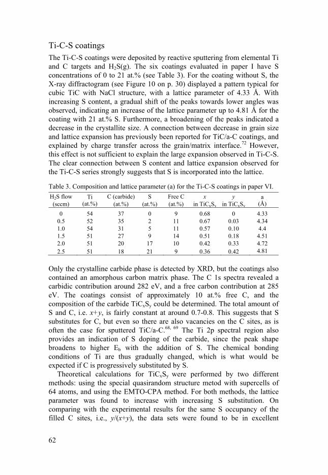
62
Ti-C-S coatings The Ti-C-S coatings were deposited by reactive sputtering from elemental Ti and C targets and H2S(g). The six coatings evaluated in paper I have S concentrations of 0 to 21 at.% (see Table 3). For the coating without S, the X-ray diffractogram (see Figure 10 on p. 30) displayed a pattern typical for cubic TiC with NaCl structure, with a lattice parameter of 4.33 Å. With increasing S content, a gradual shift of the peaks towards lower angles was observed, indicating an increase of the lattice parameter up to 4.81 Å for the coating with 21 at.% S. Furthermore, a broadening of the peaks indicated a decrease in the crystallite size. A connection between decrease in grain size and lattice expansion has previously been reported for TiC/a-C coatings, and explained by charge transfer across the grain/matrix interface.72 However, this effect is not sufficient to explain the large expansion observed in Ti-C-S. The clear connection between S content and lattice expansion observed for the Ti-C-S series strongly suggests that S is incorporated into the lattice.
Table 3. Composition and lattice parameter (a) for the Ti-C-S coatings in paper VI.
H2S flow (sccm)
Ti (at.%)
C (carbide) (at.%)
S (at.%)
Free C (at.%)
x in TiCxSy
y in TiCxSy
a (Å)
0 54 37 0 9 0.68 0 4.33 0.5 52 35 2 11 0.67 0.03 4.34 1.0 54 31 5 11 0.57 0.10 4.4 1.5 51 27 9 14 0.51 0.18 4.51 2.0 51 20 17 10 0.42 0.33 4.72 2.5 51 18 21 9 0.36 0.42 4.81
Only the crystalline carbide phase is detected by XRD, but the coatings also contained an amorphous carbon matrix phase. The C 1s spectra revealed a carbidic contribution around 282 eV, and a free carbon contribution at 285 eV. The coatings consist of approximately 10 at.% free C, and the composition of the carbide TiCxSy could be determined. The total amount of S and C, i.e. x+y, is fairly constant at around 0.7-0.8. This suggests that S substitutes for C, but even so there are also vacancies on the C sites, as is often the case for sputtered TiC/a-C.68, 69 The Ti 2p spectral region also provides an indication of S doping of the carbide, since the peak shape broadens to higher Eb with the addition of S. The chemical bonding conditions of Ti are thus gradually changed, which is what would be expected if C is progressively substituted by S.
Theoretical calculations for TiCxSy were performed by two different methods: using the special quasirandom structure metod with supercells of 64 atoms, and using the EMTO-CPA method. For both methods, the lattice parameter was found to increase with increasing S substitution. On comparing with the experimental results for the same S occupancy of the filled C sites, i.e., y/(x+y), the data sets were found to be in excellent

63
agreement, as seen in Figure 27. As the TiCxSy phase in the samples also had vacancies on the C sites, additional calculations were performed for supercells with 1/8 and 1/16 of the C sites vacant, leading to a decrease in a of 0.2 and 0.1%, respectively. The effect of S substitution is thus much larger than the effect of any vacancies, and was confirmed to be the main reason for the lattice expansion.
Figure 27. Lattice parameter as a function of the S content in TiCxSy for as-deposited and annealed coatings, and calculated structures. Adapted from paper VI.
A clue as to why substitution with S expands the unit cell was found by electronic DOS calculations for model materials TiC and TiC0.5S0.5 (Figure 15 on p. 42). For TiC there is a pseudo-gap at the Fermi level (EF), with bonding states below and antibonding states above. The DOS below EF are mainly Ti d and C p orbitals, which overlap, indicating strong Ti-C bonds. On substituting half of the C atoms for S, some of the anti-bonding states become filled, and EF is above the pseudo-gap. The overlap between Ti d and S p orbitals is small, and the Ti-S bonds are weaker than the Ti-C bonds.
The mechanical properties of the coatings were evaluated by nanoindentation. The hardness of the Ti-C coating was around 10 GPa, while the hardness of Ti-C-S coatings was lower at 5 to 7 GPa, and there was a similar change in Young’s modulus. It should be noted that the addition of S not only changes the composition of the TiCxSy phase, but also the microstructure of the nanocomposite material, and the effects of the two cannot be distinguished. However, the theoretical bulk moduli for TiCxSy structures calculated by the EMTO-CPA method were found to decrease

64
with increasing S content, suggesting that the compositional change of the carbide is responsible for at least part of the change in mechanical properties.
The current work thus demonstrates that the TiCxSy phase can be formed, but as it is not previously known, and the depositions conditions are likely to be far from thermodynamical equilibrium, it can be assumed to be metastable. It should thus be possible to remove S, and a simple test to investigate this was performed for some of the coatings presented in paper VI. The samples were placed in a 500°C furnace for 60 minutes, and when analyzed afterwards a decrease in S content and a corresponding decrease in lattice parameter was observed, as seen in Figure 27. An annealing experiment with mass spectrometry (MS) was performed for another Ti-C-S sample, similar to the coating with 21 at.% S presented above, and a blank sample of uncoated Si. While heating each sample to 700°C during 7 hours, H2S and possibly atomic S was released from the coating at around 300°C. The signal which could be atomic S may however also originate from O2, which has the same mass. Furthermore, a signal which could be either CO2 or CS had an earlier increase (around 350°C) for the sample than for the blank, and may indicate that one or both of these species are released from the coating. Lastly, a CH4 signal was observed, starting at around 100°C, for the coating. These results thus show that S leaves Ti-C-S as H2S, and possibly also S and CS, and that C may also be released from the coating. The H may originate from contaminations, and/or from the coating itself given that it is deposited from H2S.
Figure 28. The coefficient of friction for Ti-C-S running against steel, and for the S-richest coating also against W. The inset shows the wear mark on the W-coated ball in SEM, and a cross-section of the tribofilm with WS2 in TEM (micrographs from the sample preparation are seen in Figure 9 on p. 28). Adapted from paper VI.

65
Tribological properties The Ti-C-S coatings were tested against steel balls in dry air (see Figure 28), using a pin-on-disc setup with rotating geometry. TiC/a-C coatings often do not provide the very low friction seen for WS2-based coatings, and µ = 0.1-0.2 is often considered good.70 In this case, µ was found to decrease and become more stable with increasing S content, but was still about 0.2 for the two coatings with the highest S concentration. Furthermore, these two were the only ones to survive the entire test of 10 000 cycles. The improvement may be due to changes in the microstructure of the coatings, as the nanocrystallite size decreases with the addition of S, which could increase the cohesion and toughness of the coatings. The intended friction mechanism for TiC/a-C is usually the formation of graphite-like tribofilms, and a larger proportion of free C may be beneficial. In this case, however, the two coatings richest in S do not contain more free C than the others. Another possibility is that S from the coating chemically reacts to form for example FeS or FeS2, similarly to S-containing extreme pressure (EP) additives reacting with steel surfaces. Fe-S tribofilms do not provide low friction, but their presence is an improvement compared to contact between bare metal surfaces.
As studied by annealing experiments, release of S from Ti-C-S is possible, and if this could be employed to form a WS2 tribofilm there should be a significant change in the friction level. Thus, the coating richest in S was run against a W-coated steel ball. Initially, the friction was almost identical to the test against steel at µ = 0.2, but after about 500 revolutions µ had reached a lower level of µ = 0.05. As seen for the many WS2-based coatings of the previous chapters, this is a level typical for WS2 sliding in dry atmospheres, and the presence of WS2 was confirmed by Raman spectroscopy and TEM (see Figure 28). The driving force for this reaction was studied by calculating the formation energies for the compounds of the following reaction. +2 → + 2
Cases where x + y = 1 were considered, and the reaction was found to be energetically favorable for y ≤ 0.4. For higher values of y, the formed TiCx carbide becomes unstable as it will have a large proportion of vacancies. The reaction above assumes removal or all sulfur, but additional calculations (described in paper VIII) showed that partial removal of sulfur was energetically favorable also for higher values of y.
Paper VI thus proved the concept of formation of beneficial tribofilms from Ti-C-S coatings, which was further studied in paper VII. A S-rich Ti-C-S coating was then tested against balls of five different materials: 100Cr6 steel, W, WC, 316-L steel and Al2O3. The Al2O3 ball represented an

66
inert counter-surface, while the others contained tungsten (W and WC), molybdenum (316-L) and/or iron (100Cr6 and 316-L), each with the possibility of formation of sulfide tribofilms.
The tests were performed in a ball-on-disc setup with reciprocating geometry, using two different normal loads (5 and 15 N). When using steel (100Cr6 or 316-L) or W balls, the coatings survived the whole tests, while coating failure and rapid increase in friction occurred in most tests with WC or Al2O3 balls. The average coefficient of friction (until failure in applicable cases) for 100Cr6, 316-L, WC and Al2O3 balls was around 0.2. When using W balls, µ was lower, reaching levels down to µ = 0.06.
The presence of WS2 in the tribofilms from tests with W balls was confirmed by XPS, Raman and EDS analysis. WS2 or MoS2 was however not detected for tests with WC or 316-L balls. Neither the tribological performance nor the chemical analysis of the contact surfaces thus indicate that WS2 or MoS2 is formed. The formation of WS2/MoS2 should be less favorable than for pure W, since the metal is present in lower concentrations (for Mo only a few per cent in 316-L), and as a stable compound in the case of WC, decreasing the driving force for WS2 formation.
Even in the cases where WS2/MoS2 was not formed, the ball material had a clear influence on the performance, which was significantly worse for WC and Al2O3 than for 100Cr6 and 316-L steels. A suggested explanation is the formation of an iron sulfide, such as FeS or FeS2, in the contact for 100Cr6 and 316-L balls. Fe-S compounds can be used as coatings to reduce friction and wear,20 or form from steel surfaces and S-containing EP additives in lubricated steel-steel contacts.
It was thus shown that a pure metal sliding partner may be necessary for the formation of low-friction WS2/MoS2 tribofilms, but that the release of S from Ti-C-S is tribologically beneficial also for Fe-based counter-surfaces.
WS2 formation from Ti-C-(S/Se/Te) The formation of WS2 from Ti-C-S coatings was studied in papers VI and VII. A possible extension of this concept was examined in paper VIII, where the formation of TMD from a TiC phase doped with different chalcogens (S, Se and Te) was studied using first principle DFT calculations. Supercell calculations as previously described for TiCxSy were then performed also for TiCxSey and TiCxTey. In all cases, the lattice parameter monotonically increased with increasing chalcogen content. The lattice expansion was largest for Te and smallest for S, in agreement with the increase of atomic radius in the order S < Se < Te. The theoretical bulk moduli were calculated, and a decrease was seen with increasing chalcogen content, again with stronger effect in the order S < Se < Te. The bulk modulus is connected to the average bond strength, indicating that substituting C with a chalcogen leads to weaker bonds, and more so the heavier the chalcogen. The

67
electronic structures for TiCxAy (A = S, Se or Te) were compared to that of TiC by electronic DOS curves. The filling of antibonding states already observed for S was found also for Se and Te substitution, and the orbital overlap indicated that the Ti-A bonds are weaker than Ti-C bonds. For the chalcogen-containing systems there is a peak at EF which can be a sign of instability, but at least TiCxSy is obviously possible to synthesize.
The structural relationship between titanium carbide and WA2 was found to be beneficial, in that the hexagonal (111) surface of the carbide could match the hexagonal symmetry of chalcogen atoms. The match requires an expanded lattice of the carbide, which is also the case when it is doped with S/Se/Te, and the carbide should thus be a good template for WA2 formation.
The formation of WA2, and TiCx, by reaction with W was studied for all three chalcogens. For TiCxSy, it was found to be energetically favorable for y ≤ 0.4, while for Se and Te it was favorable in all of the studied range up to y = 0.4375. The energy for the reaction becomes increasingly negative in the order S < Se < Te. It should be noted, however, that all chalcogen atoms do not necessarily leave the carbide, and partial removal of S from TiCxSy was found to be more energetically favorable, and is a more likely reaction. Calculations were also performed for a situation where C atoms from the surrounding matrix in a nanocomposite occupy the sites vacated by chalcogen atoms. This was found to be a more energetically favorable reaction. However, experimental studies of annealed samples do not show any indications of increased C content in the carbide, but only a decrease in S content.
To summarize, the calculations for different chalcogens indicate that all changes observed for S substitution becomes larger for Se, and larger still for Te. The formation of WSe2 and, especially, WTe2, thus seem to be even more energetically favorable, meaning that they could be more beneficial in triboactive coatings. However, the increasingly negative energy of the reaction is mainly due to the decreased stability of the TiCxAy phase – the WA2 phase is actually also less stable for Se and Te. It is thus possible that TiCxSey and TiCxTey are not possible, or at least more difficult, to synthesize, compared to TiCxSy which was formed in every deposition from Ti, C and H2S. Furthermore, it should be noted that WTe2 is not as good a solid lubricant as the other compounds, possibly because of its slightly different structure with puckered layers.18 Still, provided that they can be synthesized and stored, nanocomposites with TiCxSey or TiCxTey may be interesting options for triboactive coatings.
Furthermore, formation of TMD layers could be of interest not only in tribofilms. The similar two-dimensional material graphene is considered interesting for a wide range of applications, and so could the TMDs. For example, they could be used as catalysts for hydrogen evolution, as electrode materials in lithium ion batteries, or in flexible electronic products.118

68
Low-friction by WS2 tribofilms For pure and alloyed WS2-based coatings alike, the intended mechanism of low friction is the formation of WS2 tribofilms on the outermost surface. To be easily sheared, these tribofilms should have the basal planes horizontally aligned, so that the sliding occurs in the easily sheared direction. It is, however, by no means necessary to have crystalline and horizontally aligned WS2 in the as-deposited coating. For crystalline coatings of type I, i.e. with standing platelets, the basal planes realign in the direction of sliding, while for amorphous or poorly crystalline TMD coatings there is a rearrangement into crystalline and aligned TMD in the contact.119-121 Ternary or quaternary WS2-based coatings may or may not contain nanocrystalline WSx grains, but in either case, WS2 tribofilms can form by atomic rearrangement as W and S are enriched in the outermost surface to form aligned layers, as observed for W-S-N coatings in paper III, and for W-S-C-(Ti) coatings in papers IV-V.
Furthermore, TMD tribofilms can form to provide low friction also when the respective elements are provided from different sources. Previously known examples are WS2 tribofilms from a W-doped carbon coating and S-containing lubricant additives, or MoS2 tribofilms from solid Mo and H2S(g).76, 122 A new approach explored in papers VI-VIII is the formation of WS2 by a tribochemical reaction with S supplied from a Ti-C-S coating, and W from a W counter-surface.
It should be noted that only a few layers of WS2 are actually needed to provide low-friction, as observed in TEM cross-sections of tribofilms from W-S-C-Ti (Figure 8) and Ti-C-S (Figure 28) coatings, and in other works.61,
62 A large number of wear tracks and marks from W-S-N coating tests were studied by Raman spectroscopy in paper III, and while it was clear that the presence of a WS2 tribofilm is connected to low friction, a stronger WS2 signal is not necessarily related to a better performance. Still, high W and S content in the coating was beneficial, especially in atmospheres with O2 and/ or H2O. The explanation is found in that the proportion of WS2 in the contact area is important, while the thickness is less important. To obtain low friction by WS2 lubrication, the sliding should be accommodated entirely in the WS2 tribofilm. For two smooth surfaces in contact, with ample supply of W and S and in an inert atmosphere, this is easily achieved, and the friction is low; µ ≤ 0.02 has been reached for WS2 sliding in this work. Non-optimal conditions may hinder this optimized sliding. The presence of O2 may lead to oxidation of WS2 to WO3, in which case the sliding partly occurs in WO3 instead. The presence of H2O seems to increase the shear strength of WS2, leading to friction levels of typically µ ≈ 0.1, as discussed in paper III. The presence of O2 and/or H2O increases the wear of the tribofilm, and thus also the demands on the supply of W and S from the coating for re-formation of WS2, as illustrated in Figure 29. This is manifested by the higher friction for coatings with high N content (low W and S content) in non-inert

69
atmospheres. In the case of W-S-C and W-S-C-Ti coatings, they can give similar and low average µ in tests, but on closer inspection the friction is less stable for W-S-C-Ti, and much higher during the running-in process. The reason for this is the presence of Ti as carbide, and in an oxidative environment as TiO2, which makes up part of the tribofilm, as observed in paper V. An analogous case has also been reported for W-S-C-Cr coatings.62 At any given time, parts of the contact should thus be in TiO2 rather than WS2, leading to higher friction, most severely so before running-in. A similar phenomenon, occurring at a longer time scale, is seen for a Ti-C-S coating running against W, with slowly decreasing µ (Figure 28) as the WS2 tribofilm is built up, eventually settling at µ < 0.03.
Figure 29. Schematic description of the formation and wear of WS2 tribofilms.
As mentioned, WS2 may also be formed from W and S originating from different sources, as described for Ti-C-S and W in papers VI-VIII. However, no formation of WS2 or MoS2 could be observed when W or Mo was present as a compound and in lower concentration, in WC and 316-L steel, respectively. The formation of sulfide from such compounds was thus not energetically favorable enough.
There are thus numerous limitations and restrictions to the possibility of WS2 tribofilm formation and the low friction it offers, but it must be remembered that more often than not, it works. The ease of formation and alignment of WS2 tribofilms, and the resulting low and stable friction, is striking, especially in WS2-based coatings. However, while WS2 tribofilms are often easily formed, their functionality in oxidative and humid environments remain a question to solve, especially as water seems to modify the intrinsic low shear strength.

70
Conclusions
The work presented in this thesis is focused on triboactive coatings, which can provide low friction under unlubricated conditions by the formation of beneficial tribofilms. The aim has been to gain an understanding of the connection between the composition and structure of the coatings, and their tribological behavior and tribofilm formation.
A number of materials systems based on tungsten disulfide, WS2, have been studied. WS2 is an excellent solid lubricant especially in inert atmospheres, and co-deposition of WS2 and additional elements gives nanocomposite or amorphous coatings which can form low-friction WS2 tribofilms. W-S-N coatings were deposited by reactive sputtering using N2(g), while W-S-C and W-S-C-Ti coatings were deposited by non-reactive sputtering. Pure W-S coatings were studied by HAXPES, as a model system for investigating possible damage caused by sputter etching performed in connection with XPS analysis. It was found that sputter etching leads to preferential removal of S, and the formation of a metallic W phase.
The W-S-N coatings were amorphous if deposited without substrate heating, but contained nanocrystalline sulfide (for low N contents) or nitride (for high N contents) if the substrate was heated during deposition. The amorphous coatings were, by theoretical and experimental methods, found to consist of an amorphous network of W, S and N, with N2 “molecules” located in nanometer-sized pockets. The nanocrystalline nitride observed in coatings deposited with substrate heating was a cubic tungsten nitride, similar to W2N but with a N/W ratio closer to 1. Its presence leads to an increase in hardness for the coating. Despite the differences in structure and mechanical properties, all W-S-N coatings exhibited an excellent tribological performance when tested in N2 atmosphere, with µ ≈ 0.02. The presence of O2, H2O, or O2 + H2O leads to progressively increased friction for each coating, and to demands on lower N content (higher W and S content) to remain in the low-friction regime. It was concluded that low friction can only be achieved if there is a steady-state WS2 tribofilm, meaning that any loss of WS2 by mechanical or chemical means must be compensated by a sufficient supply of W and S from the coating.
Co-deposition of WS2 and C leads to amorphous coatings, or nanocomposites with WSx grains in an amorphous C matrix, with some amorphous tungsten carbide. The hardness of the coatings could be increased further by the addition of Ti, for formation of Ti-C bonds. Some W-S-C-Ti

71
coatings were amorphous, but for high Ti and C contents a nanocrystalline S-doped titanium carbide phase was formed: TiCxSy. When sliding in dry air, WS2 tribofilms were formed from W-S-C and W-S-C-Ti coatings, leading to low friction levels down to µ = 0.02. The low friction was, however, less stable for Ti-containing coatings, and extremely high friction levels were observed during their running-in. This was related to the presence of TiO2 on the as-deposited coating and in the tribofilm.
A second theme in this work is coatings with the possibility of S release for tribochemical reactions and tribofilm formation. These coatings were based on titanium carbide, which was doped with S to form a metastable solid solution. Nanocomposite coatings with TiCxSy grains in an amorphous carbon matrix were deposited by reactive sputtering from elemental Ti and C targets, and H2S(g). S substitutes for C in the carbide, and lattice expansions of more than 10% were observed for high S contents. The connection between S occupancy on C sites and lattice expansion was also theoretically modelled, in excellent agreement with the experimental data. Annealing experiments showed that, as expected, S could be released from the metastable compound.
The possibility of S release was employed for the formation of beneficial tribofilms by tribochemical reactions. The friction level for a S-rich Ti-C-S coating sliding against a W counter-surface was low (µ = 0.05), and the presence of WS2 in the tribofilm was confirmed by Raman spectroscopy, TEM and XPS. No WS2 was formed in sliding against a WC counter-surface, and neither was MoS2 for a counter-surface of Mo-containing 316-L steel. However, the friction and the risk of failure was lower for steel (100Cr6 and 316-L) than for non-reactive WC and Al2O3 sliding partners. This is suggested to be due to the formation of friction-reducing iron sulfide tribofilms in sliding against steel.
To further expand this concept, the formation of TMDs from different TiCxAy (A = S, Se, Te) phases was studied by theoretical simulations. All changes observed (experimentally and theoretically) for substitution with S were increasingly strong for the heavier chalcogens Se and Te. Provided that these even more metastable materials can be synthesized, the driving force for TMD formation should be large, and they would be interesting as triboactive coatings. Furthermore, TiCxAy could be interesting as a reactant and template material for formation of two-dimensional TMDs for various applications.

72
Outlook In this work, WS2-based coatings with a large number of compositions and structures have been studied. An important conclusion is that the added element should disturb the crystallization of the sulfide during deposition, while not disturbing the WS2 tribofilm during sliding. All added elements to some extent make the WS2 formation more difficult since their presence implies a lower W and S concentration, but some are also forming high-friction and possibly abrasive metal oxides. While addition of metals and/or non-metals offesr interesting opportunities of tuning the coating properties, the amorphous W-S coatings in many cases function very well. These coatings have the benefit of increased density and hardness, while avoiding the disadvantages with added elements disturbing the tribofilm formation. Pure but amorphous W-S coatings may not be the most interesting case to study, but for applications they should definitely not be overlooked.
Among the ternary and quaternary materials systems, W-S-N coatings are a promising option. It has been suggested that the diselenides of Mo and W are more stable at high temperatures and less sensitive to humidity than the disulfides, and Mo-Se-C coatings have been reported to provide low friction and wear in inert as well as ambient conditions.123 Combining a diselenide with N by reactive sputtering with N2 should thus be an interesting approach, and the Mo-Se-N or W-Se-N systems may be good options for providing low friction also in ambient conditions.
An interesting additive element that, to my knowledge, has not been used (except as a compound, TiB2) is boron. Metal borides are, like carbides and nitrides, well-known for use in tribological coatings, although more for wear resistance than low friction. A number of tungsten borides exist, among them the superhard WB4.
124 The addition of B should hinder the formation of crystalline, soft and porous WS2, as for all other additive elements, and could also increase the hardness by formation of some tungsten boride. The formation of a B-based matrix phase is also possible, as observed for sputtered Cr-B and Nb-B coatings.125 More interestingly, it is known that for B-containing surfaces, B may react with oxygen in the air to form boron oxide (B2O3), which then reacts with moisture to form a thin boric acid (H2BO3) film. This effect has been observed for several different materials, for example borided steel surfaces, boron carbide coatings, and metal boride coatings, although annealing may be necessary for the initial B2O3 formation.126-128 The boric acid tribofilm can give ultra-low friction with µ ≈ 0.05, which is in the same range as for WS2 and other TMDs sliding in inert atmospheres. The combination of a TMD and B may thus lead to true chameleon coatings, which are doubly triboactive with different mechanisms for ultra-low friction in inert and ambient conditions, respectively. A possible risk is that the S concentration in the coatings may be low, if high borides of W are formed. Characterization may be challenging, given the

73
large number of tungsten borides and other phases that may form during the non-equlibrium conditions when sputtering. It is not unlikely that one or several phases could be doped, for example S-doped borides, a S- or W-doped boron tissue phase or a B-doped sulfide. A Me-X-B systems may thus be as complex as interesting.
Returning to the materials systems investigated in this work, they have all been tested for unlubricated sliding, in the sense that no liquid lubricant has been added. In many applications (engine parts, etc), the component is likely to be in a lubricated system. A low-friction coating may still be of large interest, as the surfaces are often in contact, either constantly or in situations such as starting or stopping, or if some failure leads to oil starvation. In such cases, a low-friction coating may limit the damage. Furthermore, there are increasingly strict environmental regulations. To supply elements (for example S) for protective tribofilms from a coating instead of oil additives can be better, since the coating consists of very little material, and offers the possibility of only releasing what is necessary at the point where it is needed. However, it is necessary to investigate how these types of coatings behave in lubricated sliding, as many new questions then arise: will a similar tribofilm be formed, will it behave in the same way, will the sliding/shearing take place in the tribofilm, will the tribofilm deteriorate, and so on.
Regarding the Ti-C-S coatings, they are not as impressive as the WS2-based ones with respect to low friction. Still, the possibility of S doping and S release is very interesting, as a proof of concept and also for other applications than ultra-low friction. TiC/a-C coatings often do not provide ultra-low friction, so S doping may still be a way of improvement. Further studies of the stability and the mechanism for S release would be interesting, and also the possible effect on other properties, for example the electrical contact resistance since TiC/a-C and related materials are investigated for use in sliding electrical contacts.
Furthermore, it may be possible to incorporate S into other similar compounds, for example other cubic carbides, or TiN. Titanium oxynitrides are well-known, and for TiN-MoS2 coatings a lattice expansion of the TiN phase has been reported, and suggested to relate to S substitution, although this was not further investigated.38, 129, 130 To perform a systematic study of the possible S doping of TiN would thus be interesting. Such depositions would likely be performed using two reactive gases, N2 and H2S, which is complicated but not impossible as shown for the deposition of W-N-S coatings in this work. A resulting S incorporation may be beneficial for tribofilm formation, but it could also change for example optical or electrical properties.

74
Sammanfattning på svenska
En viktig utmaning för dagens samhälle är att gå mot en mer hållbar utveckling, och att hushålla med resurser i form av energi och material. Ett sätt att göra detta är att minska åtgången av dessa resurser, och ett område där det finns mycket att spara är nötning och friktion – fenomen som studeras i vetenskapsområdet tribologi. Detta gäller exempelvis energi som krävs för att övervinna friktion, eller att öka livstiden för komponenter så att de inte behöver bytas ut lika ofta. De tribologiska egenskaperna beror till stor del på ytans beskaffenhet, och de kan därmed förbättras genom att förändra ytan, exempelvis genom att belägga den.
Den forskning som presenteras här handlar om keramiska ytbeläggningar som kan ge låg friktion i glidande kontakter. De är så kallat triboaktiva, vilket betyder att de förändras i den glidande kontakten med en annan yta. Det yttersta, förändrade, skiktet kallas tribofilm. Själva beläggningen är några mikrometer (tusendelars millimeter) tjock, medan tribofilmen ofta är något tiotal nanometer (miljontedelars millimeter) tjock. Trots att de är så tunna har både beläggningen och tribofilmen mycket stor inverkan på friktion och nötning. Studierna av de keramiska beläggningarna har syftat till att förstå kopplingen mellan beläggningarnas uppbyggnad, och hur de beter sig i en glidande kontakt.
Beläggningarna är deponerade med en teknik som på svenska heter katod-förstoffning, men som i allmänhet kallas sputtring (från det engelska begreppet ”sputtering”). I denna teknik slås atomer av de material som ska deponeras loss från källmaterial i en vakuumkammare, för att sedan landa på den önskade ytan. Ett eller flera grundämnen kan också tillföras i gasform, i en process som kallas reaktiv sputtring.
En grupp av beläggningsmaterial som studerats är baserade på volfram-disulfid, WS2. WS2 har en lagerstruktur som gör att den är mycket lätt-skjuvad i en riktning, och fungerar därför som ett fast smörjmedel. Materialen som studerats är kombinationer av WS2 och kväve (N), kol (C), eller kol och titan (C+Ti). I allmänhet gör kombinationen med minst ett annat grundämne att beläggningen blir tätare och i många fall amorf, det vill säga har en oordnad struktur. Tillsats av C kan göra att beläggningen delvis består av en amorf kolfas, och att även tillsätta Ti kan ge titankarbid. Tillsats av kväve ger volframnitrid, eller åtminstone W-N bindningar. Dessutom upptäcktes det att amorf W-S-N innehåller N2-”molekyler” inkapslade i

75
nanometerstora fickor i materialet, vilket bekräftades både experimentellt och teoretiskt.
Trots att själva beläggningarna inte innehåller någon kristallin WS2, så kan sådan bildas på ytan i en glidande kontakt. Denna tribofilm av WS2 blir spontant orienterad så att glidningen sker i den lättskjuvade riktningen, vilket ger mycket låg friktion. De olika WS2-baserade materialen fungerar olika bra, exempelvis kan närvaron av Ti leda till bildning av titanoxid, som ger hög friktion. Höga halter av andra grundämnen gör också att det blir lägre halter av W och S, vilket försvårar nybildningen av WS2 till tribofilmen. Det är också välkänt att denna typ av beläggningar fungerar bra i en icke-reaktiv miljö, men mindre bra i vanlig luft som innehåller bland annat syrgas (O2) och vatten (H2O). En systematisk studie av W-S-N-beläggningar i olika atmosfärer visade att O2 ökar friktionen något, H2O ökar den något mer, och båda samtidigt (som i vanlig luft) ökar den ännu mer. Detta var särskilt tydligt för beläggningar med låga W- och S-halter (alltså höga N-halter), eftersom nötningen av WS2-tribofilmen ställer höga krav på förmågan till nybildning av WS2 på ytan.
En annan typ av material som studerats är Ti-C-S, nanokompositer med korn av titankarbid (TiC) i en matris av kol, som dopades med svavel (S). Detta ledde till att S delvis ersatte C i karbiden, som då kunde beskrivas som TiCxSy. Att byta ut C mot S leder till att strukturen expanderar, eftersom S-atomer är större än C-atomer. Sambandet mellan denna expansion och S-innehållet i TiCxSy studerades både experimentellt och genom teoretiska simuleringar av materialet, med mycket god överensstämmelse, vilket bekräftade att S delvis ersätter C i karbiden.
Möjligheten att frigöra S från Ti-C-S-beläggningarna testades genom att värmebehandla dem, och den tillförda energin gjorde att en del S avgick, med en krympning av strukturen som följd. Detta skulle kunna utnyttjas exempelvis för bildning av tribofilmer, vilket också testades. När en Ti-C-S-beläggning fick glida mot en W-yta blev friktionen mycket låg, tack vare en WS2-tribofilm som bildats av S från beläggningen och W från W-ytan. Samma koncept testades mot ett antal andra ytor, men bildning av WS2 eller det liknande MoS2 observerades inte mot ytor som innehöll W i form av volframkarbid (WC), eller Mo i låg halt i ett stål. Däremot var friktionen lägre för stålytor än för icke-reaktiv aluminiumoxid (Al2O3), vilket föreslås bero på bildning av järnsulfid-tribofilmer som sänker friktionen något.
Att S kan lösas in och bilda TiCxSy visades både teoretiskt och experimentellt, och samma princip studerades även teoretiskt med selen (Se) och tellur (Te). Dessa grundämnen liknar S kemiskt, men atomerna är större och tyngre. Inlösning av Se och Te bör enligt dessa beräkningar ge samma effekter som för S, men starkare. Om dessa material kan syntetiseras kan bildningen av motsvarande lågfriktionsmaterial, disulfider och diselenider, ske förhållandevis lätt, och Ti-C-Se- och Ti-C-Te-beläggningar kan därför vara intressanta.

76
Acknowledgements
First of all, I would like to thank my main supervisor Ulf Jansson, for giving me this opportunity, and for your guidance over the years. Thank you for your enthusiasm and ideas, your good advice and encouragement, and for your supervision offering both safety and independence.
I would also like to thank my co-supervisors Staffan Jacobson and Tomas Nyberg, for support and for insights into the worlds of tribology and thin film deposition, respectively.
Thanks to Erik Särhammar, the PVD expert without whom the coatings studied here would not have existed, for your enthusiasm and hard work.
My coworkers from the materials theory group, Krisztina Kádas, Leyla Isaeva and Olle Eriksson, are acknowledged for a fruitful collaboration, and for interesting and educational discussions.
Rebecka Lindblad, Andreas Lindblad, and Mihaela Gorgoi, thank you for the showing me how stuff works at BESSY, and for making beam times such good times!
I would also like to thank Fang Mao and ABB’s Anna M. Andersson and Åke Öberg for an interesting project about Ag-based materials, Liping Wang for collaboration in the Ti-C-S project, and Soham Mukherjee and D.D. Sarma for collaboration in studying the structure of amorphous W-S-N.
Thanks to fellow thin-film PhD students Nils Nedfors, Matilda Folkenant, and Mattis Fondell, for being great colleagues and friends during all of my PhD years. Thanks to Erik Lewin for giving me and the other youngsters a good start, by teaching us a lot about work and after-work alike.
Thanks to everyone at what used to be mkem, for the lunch room discussions (“mycket bredd, lite höjd”), summer and winter parties, nationsöl, torsdagsfika, skiing trips, lunchtime runs, and so on, you have made this a great place to work! Special thanks to former and current room-mates Wendy Fredriksson and Sara Munktell, I have enjoyed sharing an office with you. Also thanks to David Rehnlund, Fredrik Lindgren and Adam Sobkowiak for good times during chemistry shows and other fun and games, and to Rickard Eriksson for being a great companion in teaching and toasting.
I would also like to thank the present and former members of the tribomaterials group, and others often seen in and around the red couches on floor 2. A special thanks to Fredrik Gustavsson for TEM tutorials and TMD discussions, to Martina Grandin for nanoindentation discussions, support,

77
and sightseeing, and to Peter Forsberg for ESCA discussions (and reinvention of some wheels). Also thanks to Petra Olander, Maria Pettersson and Jannica Heinrichs, with whom I may not have actually worked, but enjoyed the company of both at and out of Ångström.
Also thanks to my fellow members of the excecutive group for the graduate school in advanced materials for the 21st century (GradSAM21), especially coordinator Gabriella Andersson, it has been fun working with you.
I would like to acknowledge the administrative and technical staff at the department, for making all the practicalities work out, with special thanks to Pertti Knuuttila for making things run extremely smoothly at the teaching labs. Thanks also to the MSL staff, especially Jan-Åke Gustafsson for taking good care of the ESCA and its users, including this frequent one.
The Swedish Foundation for Strategic Research (SSF) is acknowledged for funding the project “Technical advancement through controlled tribofilms”, within which my work has been carried out. I would also like to thank the foundations that have made it possible for me to go to conferences all over the world: Axel Hultgren, GradSAM21, Letterstedts, Liljewalchs, Wallenbergs, Uddeholms and ÅForsk.
Furthermore, I would like to thank my chemical engineering friends for the nice monthly get-togethers, and my book club for many interesting and inspiring Sunday evenings. Special thanks to my dear friend Elin Svensson, for being such a great friend.
Then, I would like to thank my family – parents, sister, grandmother, and “Persöborna” – for always being there for me. To my parents, thank you for believing so much in me and being proud of what I do, but most of all for your love and support regardless of my achievements.
Finally and most of all, I want to thank Harald. You are a wonderful colleague and an even more wonderful partner, and finding each other is by far the best and most important discovery we have made during these years. I love you, and I am so happy to share my life with you.

78
References
1 A. Madhukar, Structural classification of layered dichalcogenides of group IV B, V B and VI B transition metals, Solid State Communications 16 (1975) 383-388. 2 P.D. Fleischauer, Fundamental aspects of the electronic structure, materials properties and lubrication performance of sputtered MoS2 films, Thin Solid Films 154 (1987) 309-322. 3 F. Jellinek, G. Brauer, H. Muller, Molybdenum and niobium sulphides, Nature 185 (1960) 376-377. 4 W.J. Schutte, J.L. De Boer, F. Jellinek, Crystal structures of tungsten disulfide and diselenide, Journal of Solid State Chemistry 70 (1987) 207-209. 5 D. Yang, R.F. Frindt, Powder X-ray diffraction of turbostratically stacked layer systems, Journal of Materials Research 11 (1996) 1733-1738. 6 J. Moser, F. Levy, Random stacking in MoS2-X sputtered thin films, Thin Solid Films 240 (1994) 56-59. 7 W.O. Winer, Molybdenum disulfide as a lubricant: A review of the fundamental knowledge, Wear 10 (1967) 422-452. 8 J.K. Lancaster, A review of the influence of environmental humidity and water on friction, lubrication and wear, Tribology International 23 (1990) 371-389. 9 H.S. Khare, D.L. Burris, The effects of environmental water and oxygen on the temperature-dependent friction of sputtered molybdenum disulfide, Tribology Letters 52 (2013) 485-493. 10 C. Donnet, J.M. Martin, T. Le Mogne, M. Belin, Super-low friction of MoS2 coatings in various environments, Tribology International 29 (1996) 123-128. 11 M. Suzuki, Tribological performance of a sputtered MoS2 film in air, N2, O2 and H2O environments at pressures from 10-5 Pa to 105 Pa, Journal of the Society of Tribologists and Lubrication Engineers 57 (2001) 23-29. 12 J.L. Grosseau-Poussard, P. Moine, M. Brendle, Shear strength measurements of parallel MoSx thin films, Thin Solid Films 307 (1997) 163-168. 13 R. Tenne, L. Margulis, M. Genut, G. Hodes, Polyhedral and cylindrical structures of tungsten disulphide, Nature 360 (1992) 444-446. 14 L. Rapoport, Y. Bilik, Y. Feldman, M. Homyonfer, S.R. Cohen, R. Tenne, Hollow nanoparticles of WS2 as potential solid-state lubricants, Nature 387 (1997) 791-793.

79
15 H.S.S. Ramakrishna Matte, A. Gomathi, A.K. Manna, D.J. Late, R. Datta, S.K. Pati, C.N.R. Rao, MoS2 and WS2 analogues of graphene, Angewandte Chemie 122 (2010) 4153-4156. 16 C. Lee, Q.Y. Li, W. Kalb, X.Z. Liu, H. Berger, R.W. Carpick, J. Hone, Frictional characteristics of atomically thin sheets, Science 328 (2010) 76-80. 17 R.M.A. Lieth, J.C.J.M. Terhell, Transition metal dichalcogenides, in: R.M.A. Lieth (Ed.) Preparation and crystal growth of materials with layered structures, D. Reidel Publishing Company, Dordrecht, Holland (1977). 18 W.A. Brainard, The thermal stability and friction of the disulfides, diselenides, and ditellurides of molybdenum and tungsten in vacuum (10-9 to 10-6 torr), NASA, Washington, D.C. (1969). 19 A. Erdemir, Boron-based solid nanolubricants and lubrication additives, in: J.M. Martin, N. Ohmae (Eds.) Nanolubricants, John Wiley & Sons, Hoboken, NJ, USA (2008). 20 H.-D. Wang, D.-M. Zhuang, K.-L. Wang, J.-J. Liu, Comparison of the tribological properties of an ion sulfurized coating and a plasma sprayed FeS coating, Materials Science and Engineering: A 357 (2003) 321-327. 21 M. Regula, C. Ballif, J.H. Moser, F. Levy, Structural, chemical, and electrical characterisation of reactively sputtered WSx thin films, Thin Solid Films 280 (1996) 67-75. 22 H. Dimigen, H. Hübsch, P. Willich, K. Reichelt, Stoichiometry and friction properties of sputtered MoSx layers, Thin Solid Films 129 (1985) 79-91. 23 K. Ellmer, Preparation routes based on magnetron sputtering for tungsten disulfide (WS2) films for thin-film solar cells, Physica Status Solidi B 245 (2008) 1745-1760. 24 E. Särhammar, E. Strandberg, J. Sundberg, H. Nyberg, T. Kubart, S. Jacobson, U. Jansson, T. Nyberg, Mechanisms for compositional variations of coatings sputtered from a WS2 target, Surface and Coatings Technology 252 (2014) 186-190. 25 L. Brewer, R.H. Lamoreaux, The Mo-S system (molybdenum-sulfur), Bulletin of Alloy Phase Diagrams 1 (1980) 93-95. 26 B. Predel, S-W (sulfur-tungsten), in: O. Madelung (Ed.) Pu-Re – Zn-Zr, Springer Berlin Heidelberg, (1998) 1-3. 27 J.R. Lince, P.D. Fleischauer, Crystallinity of R.F.-sputtered MoS2 films, Journal of Materials Research 2 (1987) 827-838. 28 J.R. Lince, D.J. Carre, P.D. Fleischauer, Effects of argon ion-bombardment on the basal-plane surface of MoS2, Langmuir 2 (1986) 805-808. 29 L.E. Rumaner, T. Tazawa, F.S. Ohuchi, Compositional change of (0001) WS2 surfaces induced by ion-beam bombardment with energies between 100 and 1500 eV, Journal of Vacuum Science & Technology A 12 (1994) 2451-2456. 30 M.A. Baker, R. Gilmore, C. Lenardi, W. Gissler, XPS investigation of preferential sputtering of S from MoS2 and determination of MoSx stoichiometry from Mo and S peak positions, Applied Surface Science 150 (1999) 255-262.

80
31 J.C. Bernede, About the preferential sputtering of chalcogen from transition metal dichalcogenide compounds and the determination of compound stoichiometry from XPS peak positions, Applied Surface Science 171 (2001) 15-20. 32 V. Buck, Structure and density of sputtered MoS2 films, Vacuum 36 (1986) 89-94. 33 K. Ellmer, C. Stock, K. Diesner, I. Sieber, Deposition of c(perpendicular to)-oriented tungsten disulfide (WS2) films by reactive DC magnetron sputtering from a W-target in Ar/H2S, Journal of Crystal Growth 182 (1997) 389-393. 34 C. Muratore, A.A. Voevodin, Control of molybdenum disulfide basal plane orientation during coating growth in pulsed magnetron sputtering discharges, Thin Solid Films 517 (2009) 5605-5610. 35 V. Weiss, S. Seeger, K. Ellmer, R. Mientus, Reactive magnetron sputtering of tungsten disulfide (WS2-x) films: Influence of deposition parameters on texture, microstructure, and stoichiometry, Journal of Applied Physics 101 (2007) 103502-103501-103509. 36 R. Gilmore, M.A. Baker, P.N. Gibson, W. Gissler, Preparation and characterisation of low-friction TiB2-based coatings by incorporation of C or MoS2, Surface and Coatings Technology 105 (1998) 45-50. 37 R. Goller, P. Torri, M.A. Baker, R. Gilmore, W. Gissler, The deposition of low-friction TiN–MoSx hard coatings by a combined arc evaporation and magnetron sputter process, Surface and Coatings Technology 120–121 (1999) 453-457. 38 R. Gilmore, M.A. Baker, P.N. Gibson, W. Gissler, M. Stoiber, P. Losbichler, C. Mitterer, Low-friction TiN–MoS2 coatings produced by dc magnetron co-deposition, Surface and Coatings Technology 108–109 (1998) 345-351. 39 S. Carrera, O. Salas, J.J. Moore, A. Woolverton, E. Sutter, Performance of CrN/MoS2(Ti) coatings for high wear low friction applications, Surface and Coatings Technology 167 (2003) 25-32. 40 J.S. Zabinski, M.S. Donley, N.T. McDevitt, Mechanistic study of the synergism between Sb2O3 and MoS2 lubricant systems using Raman spectroscopy, Wear 165 (1993) 103-108. 41 E. Arslan, Ö. Baran, I. Efeoglu, Y. Totik, Evaluation of adhesion and fatigue of MoS2–Nb solid-lubricant films deposited by pulsed-dc magnetron sputtering, Surface and Coatings Technology 202 (2008) 2344-2348. 42 B. Deepthi, H.C. Barshilia, K.S. Rajam, M.S. Konchady, D.M. Pai, J. Sankar, A.V. Kvit, Structure, morphology and chemical composition of sputter deposited nanostructured Cr-WS2 solid lubricant coatings, Surface and Coatings Technology 205 (2010) 565-574. 43 B.C. Stupp, Synergistic effects of metals co-sputtered with MoS2, Thin Solid Films 84 (1981) 257-266. 44 L.E. Pope, T.R. Jervis, M. Nastasi, Effects of laser processing and doping on the lubrication and chemical properties of thin MoS2 films, Surface and Coatings Technology 42 (1990) 217-225.

81
45 J.S. Zabinski, M.S. Donley, S.D. Walck, T.R. Schneider, N.T. McDevitt, The effects of dopants on the chemistry and tribology of sputter-deposited MoS2 films, Tribology Transactions 38 (1995) 894-904. 46 S. Mikhailov, A. Savan, E. Pflüger, L. Knoblauch, R. Hauert, M. Simmonds, H. Van Swygenhoven, Morphology and tribological properties of metal (oxide)–MoS2 nanostructured multilayer coatings, Surface and Coatings Technology 105 (1998) 175-183. 47 T.A. Lobova, E.A. Marchenko, Modified solid lubricating coatings based on tungsten diselenide, Journal of Friction and Wear 28 (2007) 193-199. 48 D.G. Teer, J. Hampshire, V. Fox, V. Bellido-Gonzalez, The tribological properties of MoS2/metal composite coatings deposited by closed field magnetron sputtering, Surface and Coatings Technology 94–95 (1997) 572-577. 49 N.M. Renevier, V.C. Fox, D.G. Teer, J. Hampshire, Coating characteristics and tribological properties of sputter-deposited MoS2/metal composite coatings deposited by closed field unbalanced magnetron sputter ion plating, Surface and Coatings Technology 127 (2000) 24-37. 50 A.A. Voevodin, J.P. O'Neill, J.S. Zabinski, Nanocomposite tribological coatings for aerospace applications, Surface and Coatings Technology 119 (1999) 36-45. 51 A.A. Voevodin, J.P. O'Neill, J.S. Zabinski, WC/DLC/WS2 nanocomposite coatings for aerospace tribology, Tribology Letters 6 (1999) 75-78. 52 A.A. Voevodin, J.S. Zabinski, Supertough wear-resistant coatings with 'chameleon' surface adaptation, Thin Solid Films 370 (2000) 223-231. 53 A. Nossa, A. Cavaleiro, The influence of the addition of C and N on the wear behaviour of W-S-C/N coatings, Surface and Coatings Technology 142 (2001) 984-991. 54 A. Nossa, A. Cavaleiro, Mechanical behaviour of W-S-N and W-S-C sputtered coatings deposited with a Ti interlayer, Surface and Coatings Technology 163 (2003) 552-560. 55 A. Nossa, A. Cavaleiro, Chemical and physical characterization of C(N)-doped W-S sputtered films, Journal of Materials Research 19 (2004) 2356-2365. 56 M. Evaristo, A. Nossa, A. Cavaleiro, W-S-C sputtered films: Influence of the carbon alloying method on the mechanical properties, Surface and Coatings Technology 200 (2005) 1076-1079. 57 A. Nossa, A. Cavaleiro, Tribological behaviour of N(C)-alloyed W-S films, Tribology Letters 28 (2007) 59-70. 58 T. Polcar, M. Evaristo, A. Cavaleiro, The tribological behavior of W-S-C films in pin-on-disk testing at elevated temperature, Vacuum 81 (2007) 1439-1442. 59 T. Polcar, M. Evaristo, A. Cavaleiro, Self-lubricating W-S-C nanocomposite coatings, Plasma Processes and Polymers 6 (2009) 417-424. 60 A. Nossa, A. Cavaleiro, N.J.M. Carvalho, B.J. Kooi, J.T.M. De Hosson, On the microstructure of tungsten disulfide films alloyed with carbon and nitrogen, Thin Solid Films 484 (2005) 389-395.
82
61 F. Gustavsson, S. Jacobson, A. Cavaleiro, T. Polcar, Ultra-low friction W–S–N solid lubricant coating, Surface and Coatings Technology 232 (2013) 541-548. 62 T. Polcar, F. Gustavsson, T. Thersleff, S. Jacobson, A. Cavaleiro, Complex frictional analysis of self-lubricant W-S-C/Cr coating, Faraday Discussions 156 (2012) 383-401. 63 J. Robertson, Diamond-like amorphous carbon, Materials Science & Engineering R 37 (2002) 129-281. 64 J.C. Sánchez-López, A. Fernández, Doping and alloying effects on DLC coatings, in: C. Donnet, A. Erdemir (Eds.) Tribology of diamond-like carbon films, Springer US, (2008) 311-338. 65 A.A. Voevodin, S.V. Prasad, J.S. Zabinski, Nanocrystalline carbide amorphous carbon composites, Journal of Applied Physics 82 (1997) 855-858. 66 M. Stüber, H. Leiste, S. Ulrich, H. Holleck, D. Schild, Microstructure and properties of low friction TiC-C nanocomposite coatings deposited by magnetron sputtering, Surface and Coatings Technology 150 (2002) 218-226. 67 Y.T. Pei, D. Galvan, J.T.M. De Hosson, Nanostructure and properties of TiC/a-C:H composite coatings, Acta Materialia 53 (2005) 4505-4521. 68 J.C. Sánchez-López, D. Martínez-Martínez, C. López-Cartes, A. Fernández, Tribological behaviour of titanium carbide/amorphous carbon nanocomposite coatings: From macro to the micro-scale, Surface and Coatings Technology 202 (2008) 4011-4018. 69 E. Lewin, O. Wilhelmsson, U. Jansson, Nanocomposite nc-TiC/a-C thin films for electrical contact applications, Journal of Applied Physics 100 (2006). 70 D. Martínez-Martínez, C. López-Cartes, A. Fernandez, J.C. Sanchez-Lopez, Influence of the microstructure on the mechanical and tribological behavior of TiC/a-C nanocomposite coatings, Thin Solid Films 517 (2009) 1662-1671. 71 J.L. Murray, Phase diagrams of binary titanium alloys, ASM International, (1989). 72 E. Lewin, M. Råsander, M. Klintenberg, A. Bergman, O. Eriksson, U. Jansson, Design of the lattice parameter of embedded nanoparticles, Chemical Physics Letters 496 (2010) 95-99. 73 Y.T. Pei, D. Galvan, J.T.M. De Hosson, A. Cavaleiro, Nanostructured TiC/a-C coatings for low friction and wear resistant applications, Surface and Coatings Technology 198 (2005) 44-50. 74 O. Wilhelmsson, M. Rasander, M. Carlsson, E. Lewin, B. Sanyal, U. Wiklund, O. Eriksson, U. Jansson, Design of nanocomposite low-friction coatings, Advanced Functional Materials 17 (2007) 1611-1616. 75 M.I. De Barros, J. Bouchet, I. Raoult, T. Le Mogne, J.M. Martin, M. Kasrai, Y. Yamada, Friction reduction by metal sulfides in boundary lubrication studied by XPS and XANES analyses, Wear 254 (2003) 863-870.

83
76 B. Podgornik, D. Hren, J. Vizintin, S. Jacobson, N. Stavlid, S. Hogmark, Combination of DLC coatings and EP additives for improved tribological behaviour of boundary lubricated surfaces, Wear 261 (2006) 32-40. 77 F. Gustavsson, P. Forsberg, V. Renman, S. Jacobson, Formation of tribologically beneficial layer on counter surface with smart chemical design of DLC coating in fuel contact, Tribology - Materials, Surfaces & Interfaces 6 (2012) 102-108. 78 H.P. Jost, Lubrication (tribology) education and research, Department of Education and Science, Her Majesty's Stationery Office, London (1966). 79 H.P. Jost, J. Schofield, Tribology's big bonus 1, Industrial Lubrication and Tribology 33 (1981) 216-226. 80 K. Holmberg, P. Andersson, A. Erdemir, Global energy consumption due to friction in passenger cars, Tribology International 47 (2012) 221-234. 81 M. Birkholz, Thin film analysis by X-ray scattering, Wiley-VCH, Weinheim (2006). 82 G.K. Williamson, W.H. Hall, X-ray line broadening from filed aluminium and wolfram, Acta Metallurgica 1 (1953) 22-31. 83 J. Walton, P. Wincott, N. Fairley, A. Carrick, Peak fitting with CasaXPS, Acolyte Science, Knutsford, UK (2010). 84 E. Lewin, P.O.Å. Persson, M. Lattemann, M. Stüber, M. Gorgoi, A. Sandell, C. Ziebert, F. Schäfers, W. Braun, J. Halbritter, S. Ulrich, W. Eberhardt, L. Hultman, H. Siegbahn, S. Svensson, U. Jansson, On the origin of a third spectral component of C1s XPS-spectra for nc-TiC/a-C nanocomposite thin films, Surface and Coatings Technology 202 (2008) 3563-3570. 85 E. Holmstrom, W. Olovsson, I.A. Abrikosov, A.M.N. Niklasson, B. Johansson, M. Gorgoi, O. Karis, S. Svensson, F. Schafers, W. Braun, G. Ohrwall, G. Andersson, M. Marcellini, W. Eberhardt, Sample preserving deep interface characterization technique, Physical Review Letters 97 (2006). 86 F. Schaefers, M. Mertin, M. Gorgoi, KMC-1: A high resolution and high flux soft x-ray beamline at BESSY, Review of Scientific Instruments 78 (2007). 87 M. Gorgoi, S. Svensson, F. Schäfers, G. Öhrwall, M. Mertin, P. Bressler, O. Karis, H. Siegbahn, A. Sandell, H. Rensmo, W. Doherty, C. Jung, W. Braun, W. Eberhardt, The high kinetic energy photoelectron spectroscopy facility at BESSY progress and first results, Nuclear Instruments and Methods in Physics Research Section A 601 (2009) 48-53. 88 W.C. Oliver, G.M. Pharr, An improved technique for determining hardness and elastic-modulus using load and displacement sensing indentation experiments, Journal of Materials Research 7 (1992) 1564-1583. 89 M. Born, R. Oppenheimer, Zur Quantentheorie der Molekeln, Annalen der Physik 389 (1927) 457-484. 90 P. Hohenberg, W. Kohn, Inhomogeneous Electron Gas, Physical Review B 136 (1964) B864-&. 91 J.P. Perdew, K. Burke, M. Ernzerhof, Generalized gradient approximation made simple, Physical Review Letters 77 (1996) 3865-3868.

84
92 P.E. Blöchl, Projector augmented-wave method, Physical Review B 50 (1994) 17953-17979. 93 G. Kresse, J. Furthmuller, Efficient iterative schemes for ab initio total-energy calculations using a plane-wave basis set, Physical Review B 54 (1996) 11169-11186. 94 L. Vitos, The EMTO-CPA method, in: Computational Quantum Mechanics for Materials Engineers, Springer London, (2007) 83-94. 95 F. Yonezawa, K. Morigaki, Coherent Potential Approximation. Basic concepts and applications, Progress of Theoretical Physics Supplement 53 (1973) 1-76. 96 A. Zunger, S.H. Wei, L.G. Ferreira, J.E. Bernard, Special quasirandom structures, Physical Review Letters 65 (1990) 353-356. 97 H.C. Andersen, Molecular dynamics simulations at constant pressure and/or temperature, The Journal of Chemical Physics 72 (1980) 2384-2393. 98 H.C. Feng, J.M. Chen, Effects of low-energy argon-ion bombardment on MoS2, Journal of Physics C 7 (1974) L75-L78. 99 R.J. Colton, J.W. Rabalais, Electronic structure of tungsten and some of its borides, carbides, nitrides, and oxides by X-ray electron spectroscopy, Inorganic Chemistry 15 (1976) 236-238. 100 J. Chastain, R.C. King, Handbook of X-ray Photoelectron Spectroscopy, Physical Electronics, Inc., Eden Prairie, MN (1995). 101 N. Mårtensson, A. Nilsson, Core-level line shapes of adsorbates: effects of electronic and vibrational excitations, Journal of Electron Spectroscopy and Related Phenomena 52 (1990) 1-46. 102 V.L. Kalikhman, Characteristics of the crystal structure, electrophysical properties, and model of the valence band spectrum of laminar compounds of molybdenum disulfide type, Neorganicheskie Materialy 19 (1983) 1060-1065. 103 C. Århammar, A. Pietzsch, N. Bock, E. Holmstrom, C.M. Araujo, J. Grasjo, S.X. Zhao, S. Green, T. Peery, F. Hennies, S. Amerioun, A. Fohlisch, J. Schlappa, T. Schmitt, V.N. Strocov, G.A. Niklasson, D.C. Wallace, J.E. Rubensson, B. Johansson, R. Ahuja, Unveiling the complex electronic structure of amorphous metal oxides, Proceedings of the National Academy of Sciences of the United States of America 108 (2011) 6355-6360. 104 M.L. Addonizio, A. Castaldo, A. Antonaia, E. Gambale, L. Iemmo, Influence of process parameters on properties of reactively sputtered tungsten nitride thin films, Journal of Vacuum Science & Technology A 30 (2012). 105 V.I. Khitrova, Z.G. Pinsker, Electron-diffraction investigation of tungsten nitrides, Soviet Physics Crystallography 3 (1958) 551-558. 106 Y.G. Shen, Y.W. Mai, Microstructure and structure characteristics of cubic WNx compounds, Materials Science and Engineering A 288 (2000) 47-53. 107 M. Wen, Q.N. Meng, W.X. Yu, W.T. Zheng, S.X. Mao, M.J. Hua, Growth, stress and hardness of reactively sputtered tungsten nitride thin films, Surface and Coatings Technology 205 (2010) 1953-1961.

85
108 D.V. Suetin, I.R. Shein, A.L. Ivanovskii, Electronic structure of cubic tungsten subnitride W2N in comparison to hexagonal and cubic tungsten mononitrides WN, Journal of Structural Chemistry 51 (2010) 199-203. 109 G. Aylward, T. Findlay, SI Chemical Data, 5th ed., John Wiley & Sons Australia, Milton, Australia (2001). 110 O.R. Monteiro, M.-P. Delplancke-Ogletree, I.G. Brown, Tungsten-containing amorphous carbon films deposited by pulsed vacuum arc, Thin Solid Films 342 (1999) 100-107. 111 C.W.E. Silva, J.R.T. Branco, A. Cavaleiro, Characterization of magnetron co-sputtered W-doped C-based films, Thin Solid Films 515 (2006) 1063-1068. 112 T. Kubart, T. Polcar, L. Kopecky, R. Novak, D. Novakova, Temperature dependence of tribological properties of MoS2 and MoSe2 coatings, Surface and Coatings Technology 193 (2005) 230-233. 113 T. Polcar, M. Evaristo, A. Cavaleiro, Comparative study of the tribological behavior of self-lubricating W-S-C and Mo-Se-C sputtered coatings, Wear 266 (2009) 388-392. 114 M. Rebelo de Figueiredo, J. Neidhardt, R. Kaindl, A. Reiter, R. Tessadri, C. Mitterer, Formation mechanisms of low-friction tribo-layers on arc-evaporated TiC1-xNx hard coatings, Wear 265 (2008) 525-532. 115 T. Polcar, R. Novák, P. Siroký, The tribological characteristics of TiCN coating at elevated temperatures, Wear 260 (2006) 40-49. 116 G. Gassner, J. Patscheider, P.H. Mayrhofer, E. Hegedus, L. Toth, I. Kovacs, B. Pecz, V. Srot, C. Scheu, C. Mitterer, Structure of sputtered nanocomposite CrCx/a-C:H thin films, Journal of Vacuum Science & Technology B 24 (2006) 1837-1843. 117 M. Andersson, J. Högström, S. Urbonaite, A. Furlan, L. Nyholm, U. Jansson, Deposition and characterization of magnetron sputtered amorphous Cr–C films, Vacuum 86 (2012) 1408-1416. 118 M. Chhowalla, H.S. Shin, G. Eda, L.J. Li, K.P. Loh, H. Zhang, The chemistry of two-dimensional layered transition metal dichalcogenide nanosheets, Nature Chemistry 5 (2013) 263-275. 119 J.M. Martin, H. Pascal, C. Donnet, T. Le Mogne, J.L. Loubet, T. Epicier, Superlubricity of MoS2: crystal orientation mechanisms, Surface and Coatings Technology 68-69 (1994) 427-432. 120 M.R. Hilton, R. Bauer, P.D. Fleischauer, Tribological performance and deformation of sputter-deposited MoS2 solid lubricant films during sliding wear and indentation contact, Thin Solid Films 188 (1990) 219-236. 121 J.L. Grosseau-Poussard, H. Garem, P. Moine, High resolution transmission electron microscopy study of quasi-amorphous MoSx coatings, Surface and Coatings Technology 78 (1996) 19-25. 122 I.L. Singer, T. Le Mogne, Superlubricity by H2S gas lubrication of Mo, in, (2007) 237-251. 123 F. Gustavsson, S. Jacobson, A. Cavaleiro, T. Polcar, Frictional behavior of self-adaptive nanostructural Mo–Se–C coatings in different sliding conditions, Wear 303 (2013) 286-296.
86
124 R. Mohammadi, A.T. Lech, M. Xie, B.E. Weaver, M.T. Yeung, S.H. Tolbert, R.B. Kaner, Tungsten tetraboride, an inexpensive superhard material, Proceedings of the National Academy of Sciences of the United States of America 108 (2011) 10958-10962. 125 N. Nedfors, Synthesis and characterization of multifunctional carbide- and boride-based thin films, Acta Universitatis Upsaliensis, Uppsala (2014). 126 C. Bindal, A. Erdemir, Ultralow friction behavior of borided steel surfaces after flash annealing, Applied Physics Letters 68 (1996) 923-925. 127 A. Erdemir, C. Bindal, G.R. Fenske, Formation of ultralow friction surface films on boron carbide, Applied Physics Letters 68 (1996) 1637-1639. 128 A. Erdemir, M. Halter, G.R. Fenske, Preparation of ultralow-friction surface films on vanadium diboride, Wear 205 (1997) 236-239. 129 S. Gangopadhyay, R. Acharya, A.K. Chattopadhyay, S. Paul, Effect of substrate bias voltage on structural and mechanical properties of pulsed DC magnetron sputtered TiN–MoSx composite coatings, Vacuum 84 (2010) 843-850. 130 J. Haider, M. Rahman, B. Corcoran, M.S.J. Hashmi, Deposition and characterization of hard-solid lubricant coating by closed-field magnetron sputtering, Surface and Coatings Technology 200 (2005) 1080-1083.


Acta Universitatis UpsaliensisDigital Comprehensive Summaries of Uppsala Dissertationsfrom the Faculty of Science and Technology 1183
Editor: The Dean of the Faculty of Science and Technology
A doctoral dissertation from the Faculty of Science andTechnology, Uppsala University, is usually a summary of anumber of papers. A few copies of the complete dissertationare kept at major Swedish research libraries, while thesummary alone is distributed internationally throughthe series Digital Comprehensive Summaries of UppsalaDissertations from the Faculty of Science and Technology.(Prior to January, 2005, the series was published under thetitle “Comprehensive Summaries of Uppsala Dissertationsfrom the Faculty of Science and Technology”.)
Distribution: publications.uu.seurn:nbn:se:uu:diva-230989
ACTAUNIVERSITATIS
UPSALIENSISUPPSALA
2014