tribology of plane strain compression tests on aluminium …mpfs/papers/scrmtof2003.pdf · ·...
TRANSCRIPT

Wear 254 (2003) 65–79
Tribology of plane strain compression tests on aluminium strip usingToF-SIMS analysis of transfer films
M.P.F. Sutcliffea,∗, R. Combarieub, M. Repouxb, P. Montmitonnetba Department of Engineering, University of Cambridge, Trumpington Street, Cambridge CB2 1PZ, UK
b Centre de Mise en Forme des Matériaux (CEMEF), CNRS UMR 7635, École Nationale Supérieure des Mines de Paris,BP 207, 06904 Sophia Antipolis, France
Received 11 February 2002; received in revised form 28 May 2002; accepted 13 September 2002
Abstract
An experimental investigation of the tribology during plane strain compression of aluminium strip using steel tools is described. Aformulated lubricant containing ester, and hexadecane containing 0, 0.05 and 0.5% stearic acid, are used as lubricants. The friction factoris measured for a wide variety of process conditions and correlated with surface analysis techniques including ToF-SIMS (time-of-flightsecondary ion mass spectroscopy). The roughness of the tool is clearly seen imprinted on the strip, indicating that any hydrodynamic orhydrostatic film separating the tool and strip is very small. With clean tools and longitudinal strip roughness, the friction stress equalsthe shear yield stress of the metal. For transverse strip roughness, hydrodynamic or hydrostatic effects lead to a reduced friction factor.With these cleaned tools there is no effect of additive concentration. After a small number of indents a transfer film builds up on the tool,leading to a fall in friction factor. The strip takes on a smeared appearance with black lines running in the direction of relative slip betweenstrip and tool. This transfer layer is of a ‘low friction slurry’ type, which is easily wiped-off using tissue paper. The effectiveness of thistransfer layer in reducing friction increases with increasing indentation speed and additive concentration. ToF-SIMS analysis shows thatthis transfer layer contains aluminium and aluminium stearate—the latter being formed specifically by reaction of stearic acid with freshmetal surface formed during deformation.© 2002 Elsevier Science B.V. All rights reserved.
Keywords:Aluminium; Plane strain compression test; Boundary lubrication; ToF-SIMS
1. Introduction
The aim of this paper is to shed light on friction duringcold strip rolling of aluminium, via an experimental studyof the tribology during plane strain compression tests onaluminium. Friction is an important component of rollingmill models used for mill control and set-up of the pro-cess conditions. Improvements in understanding of frictioncan be expected to generate significant economic benefitsby improving productivity. Furthermore, better insight intoconditions at the interface should help to develop strategiesfor improving surface quality.
The high speeds used in industrial cold rolling of alu-minium can generate significant hydrodynamic oil films inthe bite. To achieve a suitably bright strip finish, conditionsare controlled in practice so that the mean oil film separatingthe surfaces is a fraction of the height of the surface rough-
∗ Corresponding author. Tel.:+44-1223-332996;fax: +44-1223-332662.E-mail address:[email protected] (M.P.F. Sutcliffe).
ness on the tool and strip, with conditions in the so-called‘mixed’ lubrication regime. The interface between the rolland strip can be divided into valley areas separated by oiland contact areas where the roll and strip are in intimatecontact[1–4]. Whether this intimate contact is dry, or me-diated by a boundary or micro-elasto-hydrodynamic lubri-cation film (‘micro-EHL’) is an open question and probablydepends on rolling and local conditions. Friction is thenmodelled by summing up a ‘boundary friction’ componenton these contact areas and a hydrodynamic component inthe valleys. In practice the boundary friction component onthe asperity contacts tends to dominate. The most simplemodel of boundary friction assumes that the friction co-efficient is constant. More recent models have shown thatexperimental measurements of cold aluminium rolling ordrawing can be explained by assuming that the friction co-efficient decreases with increasing entraining speed[4,5].This may be because there remains some hydrodynamicaction even when oil films are only a few molecules thick,akin to quasi-hydrodynamic behaviour of thin films gen-erated in ball on disc tests[6–8]. Alternatively, this speed
0043-1648/02/$ – see front matter © 2002 Elsevier Science B.V. All rights reserved.PII: S0043-1648(02)00295-8

66 M.P.F. Sutcliffe et al. / Wear 254 (2003) 65–79
Nomenclature
a semi-width of tool in slip directionhc estimate of lubricant film thickness at the
centre of the indentk shear yield stress of strip(Y = 2k)
m friction factor (i.e. shear stressτ = mk)p̄ mean indentation pressuret (t0) semi-thickness of strip (initial value)V indentation approach speed between the toolsW width of strip transverse to slip directionY plane strain yield stress of strip
Greek lettersα lubricant pressure–viscosity coefficientε true strain in strip (ε = ln(t0/t))η0 viscosity of lubricant at ambient pressure
effect may be due to hydrodynamic action, ensuring persis-tence of the smallest wavelengths of roughness even underthese thin film conditions[9,10].
In this paper, we use the term ‘boundary lubrication’to describe conditions where friction is governed by thephysico-chemical reactions between the lubricant and themetal surfaces at the interface, as opposed to hydrodynamiclubrication where friction is governed by the rheologyof the lubricant and the geometry of the film separatingthese surfaces. It seems physically intuitive that, wherethe film thickness is of the order of molecular dimensions,physico-chemical effects at the interface will be important.However, it is not easy to separate out experimentally thetwo effects of physico-chemical reactions and hydrody-namic behaviour. For elastic contacts, this problem can beavoided by using atomically smooth surfaces (e.g. surfaceforce apparatus or atomic force microscopy, see[11]), butduring metal forming new surface is continually beingcreated, so that this approach is not feasible.
1.1. Literature review
Although, boundary friction is important in cold alu-minium rolling, there is rather scant information on how tomodel it. However, recent interest in modelling of frictionin rolling, combined with advances in surface analysis tech-niques, provide an opportunity for considerable advance inthis area. Hence, it is timely to review the disparate areasof literature having a bearing on this problem. The greatbulk of published research on boundary lubrication, bothexperimental and theoretical, considers the more commoncase where there is little if any deformation of the surfacesin contact and cannot be applied directly to modellingof boundary lubrication in metal working. Early work onboundary lubrication concentrated on the role of adsorbedmolecules[12]. However, it is clear that reactive moleculeswill adsorb chemically on the surface, particularly where,
as in metal rolling, there is considerable fresh metal sur-face formed in the bite. Wakabayashi et al.[13] illustratedthis for gas-phase lubrication of orthogonal machining,where they showed that frictional behaviour can only beunderstood in terms of a chemisorption of the lubricant atthe tool–workpiece interface. Mori et al.[14] presented astudy of chemisorption by organic compounds on a cleanaluminium surface prepared by cutting. They found that therate of absorption was proportional to the cutting speed,with absorption taking place both during and after cutting.It was suggested that the absorption rate was related to theformation rate of new aluminium surface. Equally, it mightbe expected that the oxide film behaviour will be important[15,16]. It is emphasised in[17] that aluminium and ironshow different behaviour in terms of adhesion to steel tools,associated with the brittleness of aluminium oxide as com-pared to iron oxide. Certainly, the oxide properties shouldbe taken for the high pressures in the contact, which mightmake them more ductile[18].
Previous work at the Ecole des Mines de Paris has high-lighted the role of transfer films in metal forming. These havebeen observed both in rolling and plane strain compressiontesting of a variety of metals. The most extensive series oftests have been undertaken by Kubié[19,20]using the planestrain compression test (PSCT), which is shown schemati-cally in Fig. 1. In the PSCT, flat strip is compressed betweenflat parallel platens. Where the strip is thin compared withthe width 2a of the tool, deformation is approximately ho-mogeneous in the bite. As long as the widthWof the strip islarge compared with the width 2a of the indentation, spreadis small and plane strain conditions apply. These conditionsare similar to those pertaining in cold metal rolling, justi-fying the use of such a test to model rolling. However, thePSCT tends to have different tribological conditions fromindustrial cold rolling, so that it is important to check theregime of lubrication to justify the applicability of any re-sults to rolling. In Kubié’s studies a series of indentationswas made on steel strip (using a fresh part of the strip foreach indentation). Conditions changed during the series ofindentations as the initially clean tool accumulated a transfer
Fig. 1. Schematic of the plane strain compression test.
M.P.F. Sutcliffe et al. / Wear 254 (2003) 65–79 67
layer. Recent work by Dauchot[21] and Dauchot et al.[22,23] compared rolling and PSCT of both aluminium andsteel, and related results to ToF-SIMS analysis. Duchemin[24] undertook a further series of PSCT on steel strip. Mont-mitonnet et al.[17] summarised much of this work on bothPSCT and rolling, showing that the formation of a transferlayer on the tool is key to understanding the evolution offriction during both types of tests. For PSCT on stainlesssteel, a ‘low friction slurry’ was formed which could bewiped-off the tool using an absorbing paper. Auger electronspectroscopy (AES) studies showed this film to be composedof strip metal (plus additives and lubricant, as deduced fromits slurry-like behaviour). The slurry tended to reduce theroughness of the tool by filling in the valleys. For Zircaloy al-loys a much more solid transfer layer was formed on the tool,giving rise to a significant increase in friction factor withindentation number. The effects of various factors includingtool and strip roughness, temperature and indentation speedwere investigated. All these factors played an important rolein different circumstances, though their importance for alu-minium strip does not seem to have been investigated. Rollsused to deform aluminium alloy showed an accumulation ofa relatively thick transfer film, with thicker films formed atthe edges of the strip where lubrication is poor, suggestingthat the formation of the transfer film is a function both ofthe lubrication conditions and the chemistry at the interface.
The key finding from the ToF-SIMS analysis of Dauchot[21] and Dauchot et al.[22,23]was that this method can beused to detect a variety of reacted additive species on steeland aluminium surfaces after scratching, rolling or PSCT.When the surface of aluminium was scratched while heldin lubricant, a molecular adsorption of fatty acids was ob-served. When a mixture of stearic acid and glycerol trioleatewas adsorbed onto low carbon steel during scratch tests, thestearic acid was seen to react most strongly at the lowertemperatures while at 150◦C it seemed that the acid des-orbed and trioleine became effective. PSCT on steel showedthat various additives were effective in reducing friction, asexpected. The effect of additive mixture and concentrationduring rolling was examined. For aluminium, friction coef-ficients were observed to increase slightly with rolling speed(and hence temperature), being slightly lower for lauryl al-cohol as compared with stearic acid. ToF-SIMS analysis onrolled surfaces showed an increase in aluminium hydrox-ide ions during low speed rolling in the presence of stearicacid. This confirmed the findings of Dunlop and Benmalek[25], who found a high intensity of aluminium hydroxideson rolled aluminium using ToF-SIMS. This was interpretedby Dauchot[21] as indicating the presence of reaction ofthe additive with the surface (dissociative adsorption).
Other work on boundary lubrication in metal forminghighlights the role of additives. Chambat et al.[26] showedthat organo-metallic compounds were produced during in-dustrial foil rolling of aluminium. Increasing the concentra-tion of an additive package from 0.1 to 4% was found tobring about a significant reduction in friction factor during
PSCT on steel[19]. Oleic acid at a concentration greater than1% was effective for aluminium and stearyl amine was effec-tive at much lower concentrations[19,27]. Stearic acid at 1%in mineral oil was effective at preventing metal transfer intwist–compression tests using aluminium, while the shorterchain lauric acid was ineffective, as was the unsaturated oleicacid [28]. In these tests a dark non-metallic appearance tothe tool developed with the stearic acid, through which de-tails of the anvil could be observed with a scanning electronmicroscope (SEM). It was suggested that this film was dueto reaction products. Increasing the chain length of saturatedacids at a 1% concentration in hexadecane increased the ef-fectiveness of boundary lubrication for ball-on-cylinder tests(both components being steel), with a loss of effectivenessfor the stearic acid at about 130◦C [29]. A transition temper-ature was observed in these tests at low speed, while nonewas observed at higher speeds for the 16 and 18 carbonatom additives. From this evidence it was suggested that ad-sorbed monolayers controlled friction at low speeds, whileat higher speeds partial hydrodynamic lubrication occurred,with the influence of the additives arising from the presenceof ordered monolayers. Matching of the additive and baseoil chain lengths was not found to influence the friction co-efficient. In the twist–compression and ball-on-cylinder teststhere was no bulk plastic deformation. However, the highlocal pressures at the asperity tops will lead to deformationthere, particular for the twist–compression tests with alu-minium. It is not clear how results without bulk deformationcan be used for metal forming processes. This will dependon the mechanisms controlling boundary friction, and hencethe importance of the bare metal surface created during metalforming. By shedding light on the relevant mechanisms, thepresent study aims to help answer this question.
The above paragraphs have identified the main fac-tors likely to control boundary friction in aluminium striprolling. However, our understanding is still insufficient todevelop useful quantitative physical models of boundarylubrication. Instead the boundary friction coefficient is gen-erally used as a ‘disposable parameter’ in rolling models.This significantly reduces the predictive power of thesemodels. The aim of this paper is to explore the mechanismsof boundary friction using the PSCT on aluminium, with theexpectation that the finding will also relate to cold rolling.By combining measurements of friction under differentprocess conditions with extensive surface analysis, includ-ing ToF-SIMS, more information can be obtained about thelikely mechanisms of friction than would be possible usingeither approach in isolation.
2. Experimental details
2.1. Strip
The strip material used was 1200 alloy aluminiumof initial thickness 2t0 = 0.4 mm, in the as-received

68 M.P.F. Sutcliffe et al. / Wear 254 (2003) 65–79
Fig. 2. Profilometry image of the as-received strip before indentation(Ra = 0.75�m, black dots are missing data points, pixels are 2.2�msquare).
work-hardened condition. The initial surface finish of thestrip was typical of a rolled product, as illustrated in theprofilometer image ofFig. 2, with strongly directionalroughness and anRa of 0.75�m (based on the image size710�m×530�m, after removing the mean plane). For mosttests, in which the strip roughness orientation was parallelto the direction of slip, the aluminium was cut into stripsof width W = 30 mm and length about 250 mm, allowingaround 15–20 indentations per strip. Square strips of di-mensions 30 mm× 30 mm were used for tests with the striproughness direction perpendicular to the direction of slip.
2.2. Tools
The tools were of AFNOR 100C6 grade tool steel (1% C,1.5% Cr), with a face width 2a = 5 mm and length 50 mm.For the purpose of ToF-SIMS analysis the restricted sizeof the analysis chamber required shorter tools (25 mm inlength instead of 50 mm), for which narrower strips of widthabout 17 mm were used. The tools were hand-ground using320 grit paper to produce roughnessRa values of between0.08 and 0.12�m (measured using a Perthometer contactprofilometer with a cut-off of 0.25 mm). In almost all teststhe roughness orientation of the tool was transverse to thenominal direction of slip between the tool and strip. Theschematic of the PSCT,Fig. 1, illustrates these roughnessand slip directions.
2.3. Lubricants
Two lubricants were used, a formulated rolling oil andhexadecane with stearic acid additive. The formulated oilwas Somentor N65, which has a mineral oil base andcontains >10% ester as additive. Its viscosityη0 at roomtemperature is estimated from manufacturer’s data as about0.014 Pa s. For surface analysis measurements, neat hexade-cane and hexadecane containing stearic acid in concentra-
tions of 0.05 and 0.5% by weight were used. Commerciallypure chemicals were used. The upper limit on additive con-centration was determined by the saturation limit at roomtemperature. The viscosity of the hexadecane is estimatedas around 2.1 × 10⁻³ Pa s [30]. For both oils a pressureviscosity coefficientα of 2 × 10⁻⁸ m2/N was assumed.
2.4. Test methods
After grinding, tools were inserted in the test rig, ensuringthat the tool faces were parallel. Strips were cleaned in anacetone ultrasound bath for 15 min prior to testing. In generalthe strip was then generously painted with the lubricant priorto testing using tissue paper. All tests were performed atroom temperature. A fresh piece of strip was used for eachindent. In one set of tests excess lubricant was wiped-offwith dry tissue paper, to leave a thin layer of oil. The oil filmthickness in the normal and wiped-off tests was probably ofthe order of a few hundreds of microns and a few microns,respectively. In the wiped-off case there may have been somehydrodynamic starvation, but ample additive to react withthe surface. The nominal closing speed between the twotools was normally 37 mm/min. In one series of tests thiswas reduced to 3 mm/min and in another increased to themaximum value of 110 mm/min.
Normally a mean indentation pressure of 610 MPa wasapplied during the tests. For a high friction factorm = 1, thiscorresponds to a reduction in strip thickness of around 10%.For a typical value ofm = 0.6 the reduction is around 40%while at the smallest friction factor of around 0.1 a reductionup to 85% was achieved. After indenting the specimen, thethickness at the centre of the indent was carefully measuredusing a digital micrometer.
To distinguish chemical reactions on the surface of thestrip which require both contact and strip deformation, fromsimple adsorption occurring by mere contact of the stripand oil, ToF-SIMS analyses were also performed on sam-ples dipped in lubricant. Newly ground tools and as-receivedstrips were dipped in a solution of 0.5% stearic acid in hex-adecane for 300 s, then washed in hexane to remove excesshexadecane.
2.5. Derivation of strip plane strain yield stress andextraction of friction factor
In this paper, the frictional shear stressτ is modelledusing a friction factorm, with τ = mk, wherek is the shearyield stress of the strip (which depends on the strain in thematerial). Assuming that the frictional stress is constant overthe surface of the strip and that plane strain conditions apply,the mean indentation pressurep̄ is given by
p̄ = Y(1 + ma
4t
)(1)
wheret is the semi-thickness of the strip at the end of thetest,Y the corresponding plane strain yield stress of the strip

M.P.F. Sutcliffe et al. / Wear 254 (2003) 65–79 69
(with Y = 2k) anda is the semi-width of the tool. During theindentation tests the applied mean pressurep̄ and final stripthickness 2t can be used inEq. (1)to extract a mean frictionfactorm, as long as the value of the plain strain yield stressY at the final strip thickness is known. This was found froma series of calibration PSCT experiments with a low frictioninterface of thick oil and PTFE tape. By assuming a very lowfriction factor ofm = 0.01, the measured variation of meanpressurep̄ with final thickness 2t was used, viaEq. (1), toobtain the variation ofYwith true strainε = ln(t0/t), whichwas fitted using the following expression:
Y = 140+ 15ε (Y in MPa) (2)
Although, the friction factor for these calibration tests isnot known a priori, the true value must lie within the range0–0.02, as a larger value than 0.02 gives physically inap-propriate strain softening. Since measured values of fric-tion factor during subsequent testing are significantly greaterthan 0.02, errors associated with this calibration will be in-significant. By using the PSCT for both the calibration ofYand measurements of friction, the strain pattern (includingspread of the strip in its width direction) and any anisotropyin the material are matched. Given the sensitivity of inferredfriction to flow stress, this was felt to be more reliable thanthe more direct method of using a tension test to findY.The inferred values of yield stress are below those expectedfrom industrial data for plain strain conditions on this alloy,probably because of spread of the strip.
2.6. Surface analysis
Several forms of surface analysis were performed on thesamples. Environmental SEM (Philips XL30 with LaB6 fil-ament), optical imaging, and 3D profilometry using a Zygointerferometric profilometer were used to assess the topog-raphy of the samples. Energy dispersive X-ray microanal-ysis (EDX: Oxford INCA) was used to check differencesin elementary composition on the strip. Finally ToF-SIMSwas used to identify organo-metallic products formed on thesurfaces between the strip and additives of the lubricant.
The ToF-SIMS analysis was performed on a CharlesEvans TRIFT 1 machine[31], using a 15 keV pulsed Ga+ion bombardment. Positive and negative ion spectra weretaken at a series of locations across the width of the samplewith a 235�m × 235�m square analysis window. Massresolution (m/�m) of 4000 at mass 28 was obtained onsuch surfaces. The acquisition time of each spectrum was5 min, ensuring static conditions for analysis of the organicproducts on the strip, so that the analysis depth was aboutthe first monolayers of the sample surface. Hence, particularcare was taken in cleanliness for the ToF-SIMS tests. Thetools and strips were cleaned for 15 min in a chemicallypure acetone ultrasound bath prior to PSC testing. The lu-bricant used was always a freshly prepared solution of 0.5%stearic acid in hexadecane. After indentation, samples werecut from the centre of the indented strip and were wrapped
in aluminium foil immediately after testing. They werewashed in hexane to remove excess hexadecane, prior tobe analysed shortly afterwards. By using a relatively largeanalysis window it is believed that any effect of surfaceroughness on the measurements is insignificant.
3. Results
As the aim of this work is to identify the factors govern-ing boundary lubrication, a wide range of conditions wereexplored. Tests with the formulated lubricant were usedto explore topographical and hydrodynamic effects. Testswith hexadecane and stearic acid were used to investigatethe effect of additives. ToF-SIMS analysis was also per-formed on these chemically pure lubricants, where the sim-plicity of the lubricant chemistry aids interpretation of themeasurements. Optical and SEM images and surface pro-filometry were made for all the types of test. However,results are broadly similar, and these results are only re-ported in depth for the hexadecane lubricant, where theycan be correlated with the ToF-SIMS analysis. The resultsof both sets of tests are drawn together in the discussion ofSection 4.
3.1. Formulated lubricant measurements
Fig. 3shows the evolution of friction factor and reductionwith indentation number during a series of consecutive testswith the formulated N65 lubricant on strip whose roughnesswas aligned along the direction of slip. Note that each indentwas made on a fresh piece of strip. A constant indentationpressure of 610 MPa and speed of 37 mm/min was used,except where marked. The dashed line onFig. 3 gives aschematic illustration of the mean indentation pressure. Keypoints of interest are identified by letters on the graph andare discussed below:
• The friction factorm is very close to the limiting value of1 for a newly-ground tool (A, I).
• There is a rapid fall in friction factor with indentationnumber after cleaning or regrinding the tools. Because theload was, in general, kept constant, this corresponds to anincrease in strip reduction with indentation number (e.g.A, E, I).
• The friction factor returns to the value for ground toolsafter the tools are cleaned with tissue paper (E, F).
• When the strip surface is wiped free of excess lubricant,the friction stress rises rapidly, but falls again when normalexcess lubricant conditions are reinstated (C, D).
• Friction rises rapidly when a reduced indentation speed isused, reaching a new steady state value and returning tothe original lower friction stress on a subsequent increasein indentation speed (J, K).
• The steady state friction factor does not seem to be sen-sitive to a fall in strip reduction associated with a suddendrop in load (B, H).

70 M.P.F. Sutcliffe et al. / Wear 254 (2003) 65–79
Fig. 3. Evolution of strip reduction and friction factor on strip with longitudinal roughness lubricated using N65 oil. Normal speed of 37 mm/min usedunless indicated otherwise. The variation in mean indentation pressure is shown schematically by the dashed line.
• Friction factor falls more rapidly during a series of testswith a reduced indentation load. However, on re-applyingthe normal pressure, the friction factor at first increasesbefore falling back again (F, G).
• There are slight changes in initial and steady state valuesof the friction factor when the tool roughness lies parallelto the direction of slip (L).
Although detailed optical and SEM measurements weremade on these surfaces, these are not described in detailhere, as they are broadly similar to the corresponding re-sults for the hexadecane lubricant given in the next section.Suffice to say that the relatively rough strip surface takes ona much smoother appearance after indentation, with a clearimpression of the tool grit marks running perpendicular tothe direction of slip. This indicates that any hydrodynamicfilm generated between the surfaces is very thin comparedwith the tool roughness. An exception is at the middle ofthe indent where the original strip roughness was retained.
A dark film was seen to accumulate on the tool, startingat the edges where lubrication conditions are more severeand extending towards the centre of the tool with increasingindentation number. This film was observed visually to beremoved on wiping the tool with tissue paper. The fact thatthe friction factor returns to the value for fresh tools oncleaning with tissue paper shows clearly that the reduction infriction factor with indentation number is due to this transfer
film. At the beginning of the test, with clean tools, contactconditions are particularly severe, leading to the limitingvalue of m = 1. As the transfer layer forms, conditionsin the contact become less severe. The increase in frictionassociated with a decrease in speed or lubricant supply on thestrip show that hydrodynamic effects are significant, underthe conditions tested.
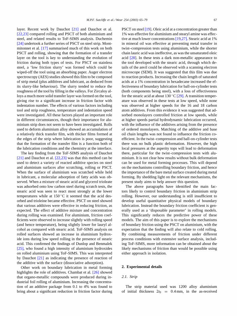
Indentation speed will play a role both in trapping oil inthe contact and in drawing it out of any pits formed on thesurface as the indentation proceeds. In both cases an increasein speed can be expected to lead to a reduction in frictionfactor, as observed. To try to separate out these effects, aseries of tests were undertaken using transverse strip rough-ness, to accentuate any hydrodynamic effects. Three speedswere used, low speed, normal speed and increasing speed.In the latter case the speed was kept low up to an indentationpressure of 300 MPa, at which point the speed was increasedtowards the normal value.Fig. 4 shows the results of thesetests. The initial friction value is lower than for the tests withlongitudinal strip roughness described above, on account ofthe favourable hydrodynamic action with transverse striproughness. The friction factor tends to fall with increasingindentation number as a transfer film builds up. The curvefor increasing speed is close to that for the normal speed,suggesting that the friction factor at the end of the test isdominated by the speed at the end of the test. This is con-sistent with the supposition that oil drawn out of pits due
M.P.F. Sutcliffe et al. / Wear 254 (2003) 65–79 71
Fig. 4. Effect of speed and pressure on the evolution of friction factor.Normal pressure (610 MPa) and normal speed (37 mm/min) used unlessindicated otherwise. Reduced pressure: 430 MPa; low speed: 3 mm/min.
to micro-plasto-hydrodynamic lubrication (MPHL)[32,33]causes the relatively low friction factor in these tests. Theeffect of pressure is also shown inFig. 4, comparing resultsat indentation pressures of 430 and 610 MPa, correspondingto reductions at the first indentation of 71 and 79%. Thereis no significant effect of pressure under these conditions.
3.2. Tests with hexadecane and stearic acid
Tests using the formulated oil, described in the previoussection, have established the importance of a transfer filmgenerated on the tool, and the role of hydrodynamic effectseven when any film separating the tool and strip seems tobe very small. The aim of the tests described in this sectionis to understand the physico-chemical processes going on inthe contact, both by surface analysis and by changing theadditive concentration in the lubricant.
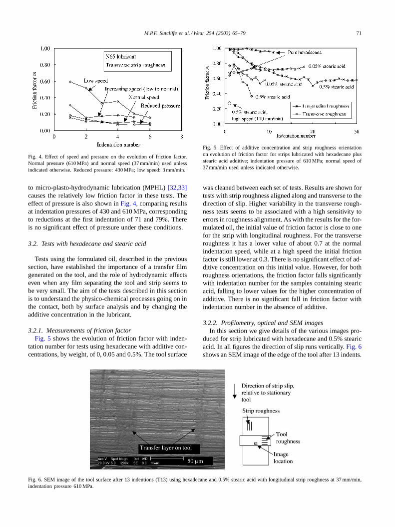
3.2.1. Measurements of friction factorFig. 5 shows the evolution of friction factor with inden-
tation number for tests using hexadecane with additive con-centrations, by weight, of 0, 0.05 and 0.5%. The tool surface
Fig. 6. SEM image of the tool surface after 13 indentions (T13) using hexadecane and 0.5% stearic acid with longitudinal strip roughness at 37 mm/min,indentation pressure 610 MPa.
Fig. 5. Effect of additive concentration and strip roughness orientationon evolution of friction factor for strips lubricated with hexadecane plusstearic acid additive; indentation pressure of 610 MPa; normal speed of37 mm/min used unless indicated otherwise.
was cleaned between each set of tests. Results are shown fortests with strip roughness aligned along and transverse to thedirection of slip. Higher variability in the transverse rough-ness tests seems to be associated with a high sensitivity toerrors in roughness alignment. As with the results for the for-mulated oil, the initial value of friction factor is close to onefor the strip with longitudinal roughness. For the transverseroughness it has a lower value of about 0.7 at the normalindentation speed, while at a high speed the initial frictionfactor is still lower at 0.3. There is no significant effect of ad-ditive concentration on this initial value. However, for bothroughness orientations, the friction factor falls significantlywith indentation number for the samples containing stearicacid, falling to lower values for the higher concentration ofadditive. There is no significant fall in friction factor withindentation number in the absence of additive.
3.2.2. Profilometry, optical and SEM imagesIn this section we give details of the various images pro-
duced for strip lubricated with hexadecane and 0.5% stearicacid. In all figures the direction of slip runs vertically.Fig. 6shows an SEM image of the edge of the tool after 13 indents.

72 M.P.F. Sutcliffe et al. / Wear 254 (2003) 65–79
Fig. 7. SEM images near the edge of the indent on the strip surface, (a) after two indents (SL2), reduction≈ 10%, (b) after nine indents (SL9),reduction≈ 25%. Indentation conditions: longitudinal strip roughness; speedV = 37 mm/min,p̄ = 610 MPa, hexadecane and 0.5% stearic acid.
Grinding marks on the tool surface are seen running hori-zontally, while traces of aluminium and carbon (identifiedusing EDX spectroscopy) are seen smeared in the directionof slip, obscuring the roughness features of the tool. Aftertwo indentations only a few particles of aluminium and car-bon were seen.Fig. 7a and bshows SEM images (usingsecondary electrons) of the strip at the edge of the indentafter two and nine indents. The tool surface is clearly seenimprinted on the strip. Black lines, running vertically in thedirection of slip, are observed here and in corresponding op-tical images[34]. It appears that the black areas correlatewith regions where the tool roughness is not imprinted onthe strip. Presumably both the black lines and the change instrip topography are due to a transfer layer forming on thetool. Profilometry measurements confirm the visual appear-ance of smearing seen in the SEM images[34].
With transverse strip roughness, the strip surface was gen-erally very smooth, with the tool roughness visible on thestrip surface, as illustrated in the SEM image ofFig. 8 forthe first indention at high speed. This again suggests thatonly a very thin film was generated between the tool andstrip. However, this smooth surface was punctuated by pits.These may act as reservoirs of lubricant which can be drawnout into the contact during deformation, either due to hydro-static pressure or MPHL[32,33].
3.2.3. ToF-SIMS analysisAll the ToF-SIMS analysis samples used hexadecane with
0.5% stearic acid as lubricant, with an indentation pressureof 610 MPa. The tools were reground and cleaned beforeeach set of tests. Typically results were on strip with lon-gitudinal roughness and the normal indentation speed of37 mm/min. Tools were measured after 0, 2 and 13 indents,while strip samples were taken after two and nine indents.One measurement was made after a single indent on a stripwith transverse roughness, indented at a maximum speedof 110 mm/min. These sample details are summarised inTable 1. Values of friction factor for the tool samples were
Table 1Details of ToF-SIMS samples
Specimen(T: tool, S: strip)
Number ofindents
Speed(mm/min)
Approximatevalue of m
Alstearates
T0 0 37 – 0T2 2 37 0.83 +T13 13 37 0.74 ++SL2 2 37 0.95 +++SL9 9 37 0.7 ++++ST1 1 110 0.3 ++The strip roughness is longitudinal in all cases except ST1, which hastransverse roughness.

M.P.F. Sutcliffe et al. / Wear 254 (2003) 65–79 73
Fig. 8. SEM image after one indent on the strip surface with transverse roughness (ST1) after indenting at 110 mm/min, indentation pressure 610 MPa,using hexadecane and 0.5% stearic acid.
probably less reliable than for corresponding strip samplesbecause of errors arising from the narrower samples used inthese cases.
This section begins with an outline of the species ob-served in the various measurements. The variation in the in-tensity of species across the width of each indent, and theirevolution with time, is then discussed. Further ToF-SIMSmeasurements are included in[34].
Fig. 9. ToF-SIMS analysis in negative mode on the tool surface showing the presence of iron and aluminium stearates: (a) cleaned tool (My: myristate,Pa: palmitate and St: Stearate), (b) at the quarter point across the width of the tool (T13) after 13 indentations on strip with longitudinal roughnessusinghexedecane with 0.5% stearic acid, (c) tool dipped in hexadecane with 0.5% stearic acid.
3.2.3.1. Tool spectra. Fig. 9ashows the tool spectrum innegative mode for the ground tool (after cleaning with ace-tone). Chlorinated and sulphured anions are observed alongwith aliphatic chains CxHy
−. Some contaminant anions,identified as laurate (C12), myristate (C14), palmitate (C16)and stearate (C18) anions, are also detected in the rangem > 198 with very low intensities. The spectrum in posi-tive mode revealed56Fe+ and52Cr+ from the steel, along
74 M.P.F. Sutcliffe et al. / Wear 254 (2003) 65–79
with the impurities Na+, K+ and Ca+ and aliphatic chainsCxHy
+.Fig. 9b and cshow the negative mass spectra for the
quarter-point across the width of the tool after 13 indenta-tions, and for the tool dipped in hexadecane plus 0.5% stearicacid. Spectra for the tool dipped in stearic acid (Fig. 9c) re-veal iron stearate anions Fe(OH)x(St)y−, with (x + y) = 3,at masses 373.2 (C18H35O2) Fe(OH)2−; 639.4 (C18H35O2)2Fe(OH)− and 905.7 (C18H35O2)3Fe−. They provide evi-dence of reaction between the iron (metallic and/or oxide)and the stearic acid due to ‘dipping’ contact to giving soaps(iron stearates). The negative mass spectrum for the tool af-ter strip indentation,Fig. 9b, shows the presence of bothiron and aluminium stearates. Positive mass spectra for thetool surface, after indenting the strip, revealed the presenceof aluminium, confirming the EDX measurements showingmetallic particles in the transfer layer seen inFig. 6.
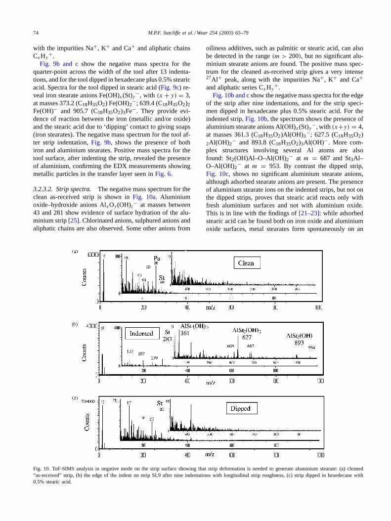
3.2.3.2. Strip spectra. The negative mass spectrum for theclean as-received strip is shown inFig. 10a. Aluminiumoxide–hydroxide anions AlxOy(OH)z− at masses between43 and 281 show evidence of surface hydration of the alu-minium strip[25]. Chlorinated anions, sulphured anions andaliphatic chains are also observed. Some other anions from
Fig. 10. ToF-SIMS analysis in negative mode on the strip surface showing that strip deformation is needed to generate aluminium stearate: (a) cleaned“as-received” strip, (b) the edge of the indent on strip SL9 after nine indentations with longitudinal strip roughness, (c) strip dipped in hexedecane with0.5% stearic acid.
oiliness additives, such as palmitic or stearic acid, can alsobe detected in the range(m > 200), but no significant alu-minium stearate anions are found. The positive mass spec-trum for the cleaned as-received strip gives a very intense27Al+ peak, along with the impurities Na+, K+ and Ca+and aliphatic series CxHy
+.Fig. 10b and cshow the negative mass spectra for the edge
of the strip after nine indentations, and for the strip speci-men dipped in hexadecane plus 0.5% stearic acid. For theindented strip,Fig. 10b, the spectrum shows the presence ofaluminium stearate anions Al(OH)x(St)y−, with (x+y) = 4,at masses 361.3 (C18H35O2)Al(OH)3
−; 627.5 (C18H35O2)2Al(OH)2
− and 893.8 (C18H35O2)3Al(OH)−. More com-plex structures involving several Al atoms are alsofound: St2(OH)Al–O–Al(OH)2− at m = 687 and St3Al–O–Al(OH)2− at m = 953. By contrast the dipped strip,Fig. 10c, shows no significant aluminium stearate anions,although adsorbed stearate anions are present. The presenceof aluminium stearate ions on the indented strips, but not onthe dipped strips, proves that stearic acid reacts only withfresh aluminium surfaces and not with aluminium oxide.This is in line with the findings of[21–23]: while adsorbedstearic acid can be found both on iron oxide and aluminiumoxide surfaces, metal stearates form spontaneously on an

M.P.F. Sutcliffe et al. / Wear 254 (2003) 65–79 75
oxidised iron surface, but not on oxidised aluminium. De-struction of the aluminium oxide layer by deformation isnecessary before aluminium stearates can be formed.
3.2.3.3. Ion abundance profiles across the tool.To find thevariation in intensity of characteristic peaks across the widthof the indentation, they are measured using Cadence® soft-ware and normalised using the total intensity of selected ionpeaks, ensuring that the evolution of the different familiesof characteristic ions do not depend on the type of normal-isation.
Fig. 11a and bgive the variations of selected speciesacross the width of the tool after 0, 2 and 13 indentations.The intensities of Al+ and aluminium stearate anions aregreatest near the edges of the tool, where the transfer filmwas observed. The variation with indentation number showshow the formation of a transfer film containing aluminium
Fig. 11. Variation of various ions across the width of the tool after 0 (T0), 2 (T2) and 13 (T13) indentations of a strip with longitudinal roughness: (a)Al+ and Fe+ ions, (b) aluminium and iron stearate anions. No aluminium or iron stearates were detected on the virgin tool T0.
and aluminium stearates is very rapid, being evident at theedges of the tool after only two indentations. The trans-fer film has expanded towards the centre after 13 indents.There is an opposite trend in the distribution of iron ions,whose intensity decreases with increasing indentation num-ber, starting at the edge and progressing towards the middle.These iron species are presumably obscured as the transferlayer builds up. At the centre of the indent the relativelythick oil film formed there appears to protect the strip sur-face, preventing the formation of aluminium stearate and atransfer film. In addition there may be a dead metal zonethere which, with the reduced sliding distance towards thecentre, may prevent formation of the transfer layer.
3.2.3.4. Ion abundance profile across the strip.Fig. 12shows the variation of intensity of characteristic ions acrossthe width of the strip surface after nine indentations. The

76 M.P.F. Sutcliffe et al. / Wear 254 (2003) 65–79
Fig. 12. Variations of characteristic ion families (aluminium and iron cations, aluminium and aluminium oxide–hydroxides anions, stearate anionsandaluminium stearate anions) across the width of strip SL9 after nine indentations. Iron comes from tool wear debris, as inferred from the Cr/Fe ratiowhich was close to that of the tool.
x-axis has been roughly zeroed using the symmetry of thetraces, so that the final indent spans±2.5 mm. The signif-icant intensity of stearate St− and aluminium stearate ionsfound towards the edges of the indent indicates greater re-action with the native aluminium there, as on the tool pro-file. By contrast oxide–hydroxides are more concentratedin the centre. In fact, their concentration is higher on theas-received strip, and they remain at this high initial con-centration wherever the tool–strip interaction level is low.This finding is mirrored by similar behaviour of contami-nant species. The evolution of Al ions in positive and neg-ative modes are not identical, perhaps due to their differentorigins. Intense positive Al ions are issued from metal oroxide layers of the strip, showing a weak peak in the centreof the indent as for the aluminium oxide–hydroxides anions.Negative Al ions profile follow stearate anions profiles, theymight be issued by the fragmentation of aluminium stearateanions during the ionisation process. The56Fe+ ions ob-served on the strip originated from tool wear (perhaps dur-ing the grinding process), as revealed from the52Cr+/56Fe+intensity ratio, which was close to the nominal compositionof the tool steel.
Fig. 13 compares the aluminium stearate ion abundanceprofiles on three strip surfaces; longitudinal roughness af-ter two and nine indentations and transverse roughness af-ter one indentation. Considering the strip samples SL2 andSL9 with longitudinal roughness, the intensity of aluminiumstearate anions on the strip increases slightly with indenta-tion number. Perhaps this is associated with an increased rateof back-transfer of material from the tool back onto the strip,as the transfer layer containing aluminium stearate buildsup. Alternatively, the reduction in strip thickness is signifi-cantly greater for the test after nine indentations due to lowerfriction, which will lead to differences in the chemistry ofthe interface between the SL2 and SL9 samples. The sample
ST1 with transverse roughness has a marginally lower inten-sity of aluminium stearate than the longitudinal roughnessspecimens. The much lower friction factor for the transversegeometry suggests a more protective oil film generated byhydrodynamic or hydrostatic lubrication. This might be ex-pected to lead to a much reduced formation of aluminiumstearates, in contrast to the observed behaviour. Perhaps thislubrication effect is counterbalanced by the much greaternew surface area created for the transverse roughness, as-sociated with the greater reduction in strip thickness, whichwould tend to increase the rate of soap formation.
Table 1summarises the intensities of the observed alu-minium stearate for the various samples, showing how thepresence of this species, marking the formation of the trans-fer layer, is associated with a decrease in friction.
Fig. 13. Comparison of normalised intensities of aluminium stearate anionsacross the width of indented strips SL2 (longitudinal roughness, twoindents), SL9 (longitudinal roughness, nine indents) and ST1 (transverseroughness, one indent).

M.P.F. Sutcliffe et al. / Wear 254 (2003) 65–79 77
4. Discussion
In this discussion section we attempt to draw together thefriction and surface analysis measurements for the two lubri-cant systems, linking these with previous research findingsas appropriate.
4.1. Mechanisms of lubrication for the first fewindentations
For the tests with longitudinal strip roughness, there is avery close conformance of the strip to the tool and the meanfrictional shear stress equals the material shear yield stressfor the first few indentations (Figs. 3 and 5). This stronglysuggests that the lubrication conditions do not generate atrue hydrodynamic oil film over a significant fraction of thesurface, and that the true area of contact is close to the nomi-nal area of contact. Under these circumstances boundary lu-brication would be expected to be the dominant mechanism.The very high values of friction factor for cleaned or groundtools, with the mean frictional stress equal to the strip shearyield stress, suggests that friction is associated with shearof the metal. This may be enhanced by the transverse toolroughness, inhibiting slip at the surface and forcing subsur-face shear. An approximate estimate of the lubricant filmthicknesshc in the central region, using Wilson’s formulafor smooth surfaces[35]:
hc = (3η0αVa2)1/3
1 − exp(−αY)(3)
gives a film thickness of around 0.4 and 1.6�m, for theformulated oil and hexadecane tests, respectively, for anapproach speedV = 37 mm/min and yield stressY =150 MPa. This film thickness, which is of the order of thestrip roughness, indicates why the strip roughness is retainedin the central region, although observations of the strip sur-face show that it is not representative of the film away fromthe central region. Under these very severe contact condi-tions changes in the chemistry of the contact do not havea significant effect. For example similar values of frictionare found in the absence of any additive (Fig. 5). Although,ToF-SIMS analysis show that there are reacted soap prod-ucts on the strip surface from the outset, it seems that dif-ferences in surface chemistry are not important for the firstfew indents.
Hydrodynamic or hydrostatic lubrication mechanismsappear to be important for the more favourable transversestrip roughness orientation. Results show a significant re-duction in friction factor for this roughness lay, and astrong dependence on speed. There is a greater reductionin friction factor with the more viscous formulated oil thanwith the hexadecane (Figs. 4 and 5). However, even herethere seems to be no influence of surface chemistry forthe first few indents, with no effect of additive concen-tration.
4.2. Transfer layer formation
After the first few indentations, a transfer film builds up onthe tool, producing a slow reversible evolution in the frictionbehaviour. The transfer film is of the ‘low friction slurry’type also observed for stainless steel[17,19]. It contains amixture of aluminium, aluminium soaps and lubricant andacts as a protective layer reducing the severity of the contactbetween the surfaces. Its development is strongly dependanton lubrication conditions. This behaviour is quite similar tothat found in strip rolling[17], although the limited amountof slip per indentation extends the time-scale considerably,allowing the kinetics to be determined and analyses to beperformed. Observations from SEM (Figs. 6 and 7) andprofilometry [34] show how the tool surface topographybecomes filled with this material. The transverse rough-ness from the tool is no longer transferred to the strip sosharply, with smearing of the strip topography presumablyassociated with the transfer layer. Here the lubricant chem-istry begins to take on a greater significance. The inclusionof additives is seen to increase the rate of transfer filmbuild-up or the significance of its effect significantly, witha corresponding reduction in the measured friction factorfor strip roughness both transverse and longitudinal to thedirection of slip (Fig. 5). These findings confirm the resultsof Nautiyal and Schey[28] using the twist–compressiontest with aluminium workpieces, who observed a similartransfer layer formation and protective effect of stearic acidadditive. Given the widespread presence of transfer films inindustrial rolling conditions, this presumably explains theindustrial importance attached to lubricant chemistry[26].
ToF-SIMS and SEM analysis show how the reacted prod-ucts found on the strip surface accumulate on the tool, start-ing at the edge where lubrication conditions are worst. Thisagrees with the observation of Montmitonnet et al. that thetransfer film builds up most strongly on the roll at the edgeof the strip, where again lubrication conditions are worst[17]. A comparison of the dipped and indented strip showhow the generation of new surface is critical to the forma-tion of soaps, supporting the findings in[14,21–23]. How-ever, hydrodynamic effects still seem to be very importantfor these conditions in determining both the friction factorat a given instance and the evolution of the transfer film.For example, the effect of reducing the speed or lubricantsupply on the strip significantly increases the friction factorunder ‘steady state’ conditions (c.f.Fig. 3, C, D, J). Againthis conforms with the observation of Montmitonnet et al.for rolling, who show that the build-up of a transfer filmis a dynamic process, with film being changed or removedunder poor lubrication conditions.
4.3. Tool and strip roughness
The effect of changing the strip roughness orientationfrom longitudinal to transverse was very significant. Thisis attributed to the different hydrodynamic conditions, with

78 M.P.F. Sutcliffe et al. / Wear 254 (2003) 65–79
the transverse roughness more effectively trapping oil in thebite, which is then subsequently drawn out. The limited ex-ploration (Fig. 3, L) of tool roughness orientation showedthat the effect of changing from transverse to longitudinaltool roughness was relatively slight, no doubt because themagnitude of the strip roughness was considerably greaterthan the tool roughness for conditions explored. An alter-native source of complexity is that in the majority of testsundertaken in this work, the roughness of the tool and stripare at right angles. This forces continual deformation of thestrip surface as asperities on the tool ‘plough’ through thestrip, which may contribute to the high friction factor foundbefore the transfer layer builds up. It may also be that thisrepeated action generates wear particles from the strip andso enhances any accumulation of a transfer layer (c.f.[36]).By contrast, in rolling the roughness lays of both strip androll are generally parallel to the direction of slip, giving lesssevere sliding conditions.
4.4. Comparison with rolling
The conditions used in these tests were chosen to tryto generate boundary lubrication conditions. In practice itseems that the tests were in a mixed hydrodynamic andboundary regime, with the formation of a transfer film play-ing a key role. In rolling, the presence of some hydrodynamicaction suggests that similar conditions will apply. Moreover,a transfer film is observed in aluminium rolling, support-ing the usefulness of these tests in understanding lubricationmechanisms in rolling. Although, industrial rolls frequentlybecome coated in a transfer layer which seems to be stronglyattached, this was not the case in these tests, where the trans-fer film was easily removed using absorbent paper. Perhapsthe higher temperatures found in industrial rolling lead todesorption of additives. Alternatively, the longer sliding dis-tances and consequent continued shearing of the layers maylead to a greater attachment of the transfer layer in theseconditions[17]. The use of different base oils and additivesin rolling, as compared with these experiments, is expectedto change significantly the quantitative results. Differencesin the tribology associated with the very different slidingconditions between the tool and strip in rolling and PSCTmay also be significant, along with temperature effects.
5. Conclusions
Plane strain compression tests (PSCT) have been per-formed on aluminium strip using steel tools. Both a formu-lated lubricant containing ester as additive and a lubricantcomprised of hexadecane plus stearic acid additive in con-centrations of 0, 0.05 and 0.5% were used. The frictionfactor m (with τ = mk) was estimated for a variety ofprocess conditions and correlated with surface analysistechniques, including SEM, profilometry and ToF-SIMS.The strip surface conformed very closely to the tool except
at the middle of the indent, suggesting that only a very thinoil film, if any, could separate the tool and strip surfaces, sothat conditions are apparently in the regime that would nor-mally be considered as boundary lubrication. The followingconclusions can be drawn:
1. For the first few indents with the strip roughness parallelto the direction of slip, the friction factor was close toone, implying shearing of the strip metal surface. Resultswere the same for the two lubricants used, and were in-dependent of additive concentration. For transverse striproughness, hydrodynamic or hydrostatic lubrication ef-fects led to a reduced friction factor. Again there was noeffect of additive concentration within the range of con-ditions tested.
2. After a few indents a transfer layer built up on the tool,leading to a significant fall in friction factor. The striptook on a smeared appearance with black lines runningin the direction of slip on the strip surface. This transferlayer was of the ‘low friction slurry’ type, and could beeasily removed with an absorbent paper. The reductionin friction associated with this transfer layer increasedwith increasing additive concentration and increasinghydrodynamic or hydrostatic lubrication effects (as ev-idenced by effects of speed, roughness orientation andoil starvation).
3. ToF-SIMS analysis revealed the presence of stearateand aluminium stearate ions on both the tool and strip,spreading from the edge of the indent towards the mid-dle with increasing indentation number. The presenceof aluminium stearate gave evidence of adsorption andreaction of the stearic acid with the bare aluminiumsurface. Aluminium stearate was not found due to merecontact of the aluminium with stearic acid, in the absenceof bulk deformation.
Acknowledgements
Thanks are due to Suzanne Jacomet and Huirong Le fortheir assistance.
References
[1] S. Sheu, W.R.D. Wilson, Mixed lubrication of strip rolling, STLETribology Trans. 37 (1994) 483–493.
[2] M.P.F. Sutcliffe, K.L. Johnson, Lubrication in cold strip rolling inthe ‘mixed’ regime, Proc. Instn. Mech. Eng. 204 (1990) 249–261.
[3] H.S. Lin, N. Marsault, W.R.D. Wilson, A mixed lubrication modelfor cold strip rolling—Part I: Theoretical, Tribol. Trans. 41 (1998)317–326.
[4] N. Marsault, P. Montmitonnet, P. Deneuville, P. Gratacos, A modelof mixed lubrication for cold rolling of strip, in: A.A. Balkema (Ed.),Proceedings of NUMIFORM’98, Twente University, Rotterdam, TheNetherlands, 1998, pp. 715–772.
[5] H.R. Le, M.P.F. Sutcliffe, A semi-empirical friction model for coldmetal rolling, Tribol. Trans. 44 (2) (2001) 284–290.

M.P.F. Sutcliffe et al. / Wear 254 (2003) 65–79 79
[6] G.J. Johnston, R. Wayte, H.A. Spikes, The measurement and studyof very thin lubricant films in concentrated contacts, Tribol. Trans.34 (1991) 187–194.
[7] H. Spikes, The borderline of elastohydrodynamic and boundarylubrication, Proc. Instn. Mech. Eng. 214C (2000) 23–37.
[8] J. Molimard, M. Querry, P. Vergne, Rhéologie des lubrifiants enconditions réelles: mesure et confrontation à un contact bille-disque,Rev. Mét. CIT/SGM (2001) 141–148.
[9] H.R. Le, M.P.F. Sutcliffe, A two-wavelength model of surfaceflattening in cold metal rolling with mixed lubrication regime, STLETribol. Trans. 43 (4) (2000) 595–602.
[10] M.P.F. Sutcliffe, H.R. Le, Measurements of surface roughness in coldmetal rolling in the mixed lubrication regime, STLE Tribol. Trans.43 (2000) 39–44.
[11] B. Bhusan, J.N. Israelachvili, U. Landman, Nanotribology: friction,wear and lubrication at the atomic scale, Nature 374 (1995) 607–616.
[12] C.N. Rowe, Some aspects of the heat of adsorption in the functionof boundary lubrication, ASLE Trans. 9 (1966) 101–111.
[13] T. Wakabayashi, J.A. Williams, I.M. Hutchings, The kinetics ofgas-phase lubrication in the orthogonal machining of an aluminiumalloy, Proc. Instn. Mech. Eng. 209 (1995) 131–136.
[14] S. Mori, M. Suginoya, Y. Tamai, Chemisorption of organiccompounds on a clean aluminium surface prepared by cutting underhigh vacuum, ASLE Trans. 25 (2) (1982) 261–266.
[15] D.R. Milner, G.W. Rowe, Fundamentals of solid-phase welding,Metall. Rev. 7 (1962) 433–480.
[16] Y.H. Li, M. Krzyzanowski, J.H. Beynon, C.M. Sellars, Physicalsimulation of interfacial conditions in hot forming of steels, in:Proceedings of the 3rd International Conference on Physical andNumerical Simulation of Materials and Hot Working (ICPNS’99),Beijing, China, 1999.
[17] P. Montmitonnet, F. Delamare, B. Rizoulières, Transfer layer andfriction in cold metal strip rolling processes, Wear 245 (1–2) (2000)125–135.
[18] V.L. Kolmogorov, A.G. Zalazinski, On metal joining and theprediction of solid-phase joints, J. Mater. Process. Technol. 75 (1998)157–164.
[19] J. Kubié, Le test de bipoinçonnement: étude théorique—applicationà l’étude du transfert de matière dans un contact frottant, Ph.D.Thesis, École des Mines de Paris, 1980.
[20] F. Delamare, M. de Vathaire, J. Kubié, An evaluation of the plainstrain compression test. Experimental study of the friction test. II.Role of transfer layers in boundary lubrication, J. Lubric. Tech. 104(1982) 545–551.
[21] G. Dauchot, Tribochimie du laminage à froid des aciers bas carboneet des alliages d’aluminium. Étude par ToF-SIMS de la chimisorption
des additifs de lubrification, Ph.D. Thesis, École des Mines de Paris,1999.
[22] G. Dauchot, Y. De Puydt, R. Combarieu, M. Repoux, F. Delamare,in: G. Gillen, R. Lareau, J. Bennett, F. Stevie (Eds.), Proceedings ofthe SIMS XI Conference on ToF-SIMS Evidence of TribochemicalReactions in the Cold Rolling of Steel, Wiley, New York, 1997,pp. 513–516.
[23] G. Dauchot, R. Combarieu, P. Montmitonnet, M. Repoux, G.Dessalces, F. Delamare, Tribochemical reactions in cold rolling: aToF-SIMS study of the chemisorption of the lubricant additives onthe sheet, Revue de Métallurgie-CIT/Science et Génie des Matériaux,2001, pp. 159–169.
[24] M. Duchemin, Physico-chimie des couches superficielles enlaminage: contact outil-métal-lubrifiant. Étude par bipoinçonnementà chaud, Stage report, École des Mines de Paris, 1998.
[25] H.M. Dunlop, M. Benmalek, Role and characterization of surfaces inthe aluminium industry, J. Phys. IV: France 7 (C6) (1997) 163–174.
[26] F. Chambat, M. Lashermes, H. Hendricks, Organometallic com-pounds produced during aluminium cold rolling, Lubric. Eng. 43(1987) 522–527.
[27] W.G. Johnston, R.E. Atkinson, Lubric. Eng. 32 (1976) 242.[28] P.C. Nautiyal, J.A. Schey, Transfer of aluminium to steel in sliding
contact: effects of lubicant, ASME J. Tribol. 112 (1990) 282–287.
[29] S. Jahanmir, Chain length effects in boundary lubrication, Wear 102(1985) 331–349.
[30] J.A. Schey, Metal Working, Metal Deformation Processes; Frictionand Lubrication, Marcel-Dekker, New York, 1970, p. 348.
[31] B.W. Schueler, Microscope imaging by time-of-flight secondary ionmass-spectrometry, Microsc. Microanal. Microstruct. 3 (1992) 119–139.
[32] S.W. Lo, A theoretical model of micro-pool lubrication in metalforming, in: Proceedings of the First International Conference onTribology in Manufacturing Processes, Gifu, Japan, 1997, pp. 83–90.
[33] M.P.F. Sutcliffe, H.R. Le, R. Ahmed, Modelling of micro-pitevolution in rolling or strip drawing, ASME J. Tribol. 123 (2001)791–798.
[34] M.P.F. Sutcliffe, R. Combarieu, M. Repoux, P. Montmitonnet,Plane strain compression tests on aluminium strip with ToF-SIMSanalysis, Cambridge University Engineering Department, ReportCUED MAT/TR62, 2002.
[35] W.R.D. Wilson, An isoviscous model for the hydrodynamiclubrication of plane strain forging processes with flat dies, J. Lub.Technol. Trans. ASME 95 (4) (1974) 539–546.
[36] A. Kapoor, K.L. Johnson, Plastic ratchetting as a mechanism ofmetallic wear, Proc. R. Soc. London, Ser. A 445 (1994) 367–381.