trimble bd970 gnss receiver module user guide introduction 8 bd970 gnss receiver module user guide...
TRANSCRIPT
USER GUIDE
Trimble® BD970 GNSSReceiver Module


Version 4.40Revision AMay 2011 F
USER GUIDE
Trimble® BD970 GNSS Receiver Module

2 BD970 GNSS Receiver Module User Guide
Corporate OfficeTrimble Navigation Limited935 Stewart DriveSunnyvale, CA 94085USAwww.trimble.comE-mail: [email protected]
Legal Notices© 2006–2011, Trimble Navigation Limited. All rights reserved. Trimble, and the Globe & Triangle logo are trademarks of Trimble Navigation Limited, registered in the United States and in other countries. CMR+, Zephyr, and Zephyr Geodetic are trademarks of Trimble Navigation Limited.Microsoft, Internet Explorer, Windows, and Windows NT are either registered trademarks or trademarks of Microsoft Corporation in the United States and/or other countries.All other trademarks are the property of their respective owners.
Release NoticeThis is the May 2011 release (Revision A) of the BD970 GNSS Receiver Module User Guide. It applies to version 4.40 of the receiver firmware.
Restriction of Use of Certain Hazardous Substances in Electrical and Electronic Equipment (RoHS)This Trimble product complies in all material respects with DIRECTIVE 2002/95/EC OF THE EUROPEAN PARLIAMENT AND OF THE COUNCIL of 27 January 2003 on the restriction of the use of certain hazardous substances in electrical and electronic equipment (RoHS Directive) and Amendment 2005/618/EC filed under C(2005) 3143, with exemptions for lead in solder pursuant to Paragraph 7 of the Annex to the RoHS Directive applied.
Waste Electrical and Electronic Equipment (WEEE)For product recycling instructions and more information, please go to www.trimble.com/ev.shtml. Recycling in Europe: To recycle Trimble WEEE (Waste Electrical and Electronic Equipment, products that run on electrical power.), Call +31 497 53 24 30, and ask for the "WEEE Associate". Or, mail a request for recycling instructions to:Trimble Europe BVc/o Menlo Worldwide LogisticsMeerheide 455521 DZ Eersel, NL

Contents1 Introduction . . . . . . . . . . . . . . . . . . . . . . . . . . . . . . . . . . . . 7
About the BD970 receiver . . . . . . . . . . . . . . . . . . . . . . . . . . . . . . . . . . . . . . . . . . . . . 8Related information . . . . . . . . . . . . . . . . . . . . . . . . . . . . . . . . . . . . . . . . . . . . . . . . 8Technical support . . . . . . . . . . . . . . . . . . . . . . . . . . . . . . . . . . . . . . . . . . . . . . . . . . 8
2 Features and Functions . . . . . . . . . . . . . . . . . . . . . . . . . . . . . . 9BD970 receiver features . . . . . . . . . . . . . . . . . . . . . . . . . . . . . . . . . . . . . . . . . . . . . 10Use and care . . . . . . . . . . . . . . . . . . . . . . . . . . . . . . . . . . . . . . . . . . . . . . . . . . . . 11Radio and radar signals . . . . . . . . . . . . . . . . . . . . . . . . . . . . . . . . . . . . . . . . . . . . . 11COCOM limits . . . . . . . . . . . . . . . . . . . . . . . . . . . . . . . . . . . . . . . . . . . . . . . . . . . 11
3 Installation . . . . . . . . . . . . . . . . . . . . . . . . . . . . . . . . . . . . 13Receiver setup . . . . . . . . . . . . . . . . . . . . . . . . . . . . . . . . . . . . . . . . . . . . . . . . . . . 14Installing the BD970 receiver . . . . . . . . . . . . . . . . . . . . . . . . . . . . . . . . . . . . . . . . . . 14
Unpacking and inspecting the shipment . . . . . . . . . . . . . . . . . . . . . . . . . . . . . . 14Supported antennas . . . . . . . . . . . . . . . . . . . . . . . . . . . . . . . . . . . . . . . . . . . 15Installation guidelines . . . . . . . . . . . . . . . . . . . . . . . . . . . . . . . . . . . . . . . . . . 15Mounting the antennas . . . . . . . . . . . . . . . . . . . . . . . . . . . . . . . . . . . . . . . . . 15BD970 interface board . . . . . . . . . . . . . . . . . . . . . . . . . . . . . . . . . . . . . . . . . 16Routing and connecting the antenna cable . . . . . . . . . . . . . . . . . . . . . . . . . . . . 17
LED functionality and operation . . . . . . . . . . . . . . . . . . . . . . . . . . . . . . . . . . . . . . . 18
4 Positioning Modes . . . . . . . . . . . . . . . . . . . . . . . . . . . . . . . . 19What is RTK?. . . . . . . . . . . . . . . . . . . . . . . . . . . . . . . . . . . . . . . . . . . . . . . . . . . . 20Carrier phase initialization . . . . . . . . . . . . . . . . . . . . . . . . . . . . . . . . . . . . . . . . . . . 20Update rate and latency . . . . . . . . . . . . . . . . . . . . . . . . . . . . . . . . . . . . . . . . . . . . . 20Data link. . . . . . . . . . . . . . . . . . . . . . . . . . . . . . . . . . . . . . . . . . . . . . . . . . . . . . . 21Moving Baseline RTK positioning . . . . . . . . . . . . . . . . . . . . . . . . . . . . . . . . . . . . . . . 21Critical factors affecting RTK accuracy . . . . . . . . . . . . . . . . . . . . . . . . . . . . . . . . . . . 22
Base station receiver type. . . . . . . . . . . . . . . . . . . . . . . . . . . . . . . . . . . . . . . . 22Base station coordinate accuracy. . . . . . . . . . . . . . . . . . . . . . . . . . . . . . . . . . . 22Number of visible satellites. . . . . . . . . . . . . . . . . . . . . . . . . . . . . . . . . . . . . . . 22Elevation mask . . . . . . . . . . . . . . . . . . . . . . . . . . . . . . . . . . . . . . . . . . . . . . 23Environmental factors. . . . . . . . . . . . . . . . . . . . . . . . . . . . . . . . . . . . . . . . . . 23Operating range. . . . . . . . . . . . . . . . . . . . . . . . . . . . . . . . . . . . . . . . . . . . . . 24
DGPS. . . . . . . . . . . . . . . . . . . . . . . . . . . . . . . . . . . . . . . . . . . . . . . . . . . . . . . . . 24SBAS . . . . . . . . . . . . . . . . . . . . . . . . . . . . . . . . . . . . . . . . . . . . . . . . . . . . . . . . . 24
5 Configuring the BD970 Receiver Using Trimble Software Utilities . . . . . 25Configuration Toolbox software . . . . . . . . . . . . . . . . . . . . . . . . . . . . . . . . . . . . . . . . 26
Creating and editing application files . . . . . . . . . . . . . . . . . . . . . . . . . . . . . . . . 26Trimble MS Controller or Winpan software . . . . . . . . . . . . . . . . . . . . . . . . . . . . . . . . 28
Simulated LCD display . . . . . . . . . . . . . . . . . . . . . . . . . . . . . . . . . . . . . . . . . 28Softkeys . . . . . . . . . . . . . . . . . . . . . . . . . . . . . . . . . . . . . . . . . . . . . . . . . . . 29Simulated keypad. . . . . . . . . . . . . . . . . . . . . . . . . . . . . . . . . . . . . . . . . . . . . 29
BD970 GNSS Receiver Module User Guide 3

Function keys . . . . . . . . . . . . . . . . . . . . . . . . . . . . . . . . . . . . . . . . . . . . . . . 30Working with screens and fields . . . . . . . . . . . . . . . . . . . . . . . . . . . . . . . . . . . 30Entering data in fields . . . . . . . . . . . . . . . . . . . . . . . . . . . . . . . . . . . . . . . . . . 31
6 Configuring the BD970 Receiver Using a Web Browser . . . . . . . . . . . 33Configuring Ethernet settings . . . . . . . . . . . . . . . . . . . . . . . . . . . . . . . . . . . . . . . . . 34Configuring the receiver using a web browser . . . . . . . . . . . . . . . . . . . . . . . . . . . . . . . 37
Supported browsers . . . . . . . . . . . . . . . . . . . . . . . . . . . . . . . . . . . . . . . . . . . 37Changing the settings . . . . . . . . . . . . . . . . . . . . . . . . . . . . . . . . . . . . . . . . . . 38
Establishing a PPP connection. . . . . . . . . . . . . . . . . . . . . . . . . . . . . . . . . . . . . . . . . 47
7 Configuring the BD970 Receiver Using Binary Interface Commands . . . . 57RS-232 Serial Interface Specification . . . . . . . . . . . . . . . . . . . . . . . . . . . . . . . . . . . . . 58
Communications format . . . . . . . . . . . . . . . . . . . . . . . . . . . . . . . . . . . . . . . . 58Testing the communications link . . . . . . . . . . . . . . . . . . . . . . . . . . . . . . . . . . . 59Communication errors . . . . . . . . . . . . . . . . . . . . . . . . . . . . . . . . . . . . . . . . . 59Data Collector Format packets . . . . . . . . . . . . . . . . . . . . . . . . . . . . . . . . . . . . 59Data Collector Format packet structure . . . . . . . . . . . . . . . . . . . . . . . . . . . . . . 60Data Collector Format packet functions . . . . . . . . . . . . . . . . . . . . . . . . . . . . . . 60The receiver STATUS byte . . . . . . . . . . . . . . . . . . . . . . . . . . . . . . . . . . . . . . . 61Reading binary values . . . . . . . . . . . . . . . . . . . . . . . . . . . . . . . . . . . . . . . . . . 61INTEGER data types . . . . . . . . . . . . . . . . . . . . . . . . . . . . . . . . . . . . . . . . . . . 62
Data Collector Format Command Packets . . . . . . . . . . . . . . . . . . . . . . . . . . . . . . . . . 6406h, GETSERIAL (Receiver and antenna information request) . . . . . . . . . . . . . . . . 6554h, GETSVDATA (Satellite information request) . . . . . . . . . . . . . . . . . . . . . . . . 6656h, GETRAW (Position or real-time survey data request) . . . . . . . . . . . . . . . . . . . 6764h, APPFILE (Application file record command) . . . . . . . . . . . . . . . . . . . . . . . . 6865h, GETAPPFILE (Application file request) . . . . . . . . . . . . . . . . . . . . . . . . . . . . 8266h, GETAFDIR (Application file directory listing request). . . . . . . . . . . . . . . . . . . 8368h, DELAPPFILE (Delete application file data command) . . . . . . . . . . . . . . . . . . 846Dh, ACTAPPFILE (Activate application file) . . . . . . . . . . . . . . . . . . . . . . . . . . . 8581h, KEYSIM (Key simulator) . . . . . . . . . . . . . . . . . . . . . . . . . . . . . . . . . . . . . 8682h, SCRDUMP (Screen dump request) . . . . . . . . . . . . . . . . . . . . . . . . . . . . . . . 88
Data Collector Format Report Packets. . . . . . . . . . . . . . . . . . . . . . . . . . . . . . . . . . . . 89Report Packet summary . . . . . . . . . . . . . . . . . . . . . . . . . . . . . . . . . . . . . . . . 8907h, RSERIAL (Receiver and antenna information report) . . . . . . . . . . . . . . . . . . . 9040h, GENOUT (General output record reports) . . . . . . . . . . . . . . . . . . . . . . . . . . 92GSOF record types . . . . . . . . . . . . . . . . . . . . . . . . . . . . . . . . . . . . . . . . . . . . 9355h, RETSVDATA (Satellite information reports). . . . . . . . . . . . . . . . . . . . . . . . .12157h, RAWDATA (Position or real-time survey data report). . . . . . . . . . . . . . . . . . .12664h, APPFILE (Application file record report) . . . . . . . . . . . . . . . . . . . . . . . . . . .13567h, RETAFDIR (Directory listing report). . . . . . . . . . . . . . . . . . . . . . . . . . . . . .1366Eh, BREAKRET (Break sequence return) . . . . . . . . . . . . . . . . . . . . . . . . . . . . .13882h, SCRDUMP (Screen dump) . . . . . . . . . . . . . . . . . . . . . . . . . . . . . . . . . . . .141
8 Default Settings . . . . . . . . . . . . . . . . . . . . . . . . . . . . . . . . 143Default receiver settings . . . . . . . . . . . . . . . . . . . . . . . . . . . . . . . . . . . . . . . . . . . . .144
4 BD970 GNSS Receiver Module User Guide

9 Specifications. . . . . . . . . . . . . . . . . . . . . . . . . . . . . . . . . . 145Physical specifications . . . . . . . . . . . . . . . . . . . . . . . . . . . . . . . . . . . . . . . . . . . . . .146Performance specifications . . . . . . . . . . . . . . . . . . . . . . . . . . . . . . . . . . . . . . . . . . .146Electrical specifications . . . . . . . . . . . . . . . . . . . . . . . . . . . . . . . . . . . . . . . . . . . . .147Communication specifications . . . . . . . . . . . . . . . . . . . . . . . . . . . . . . . . . . . . . . . .147
A NMEA-0183 Output . . . . . . . . . . . . . . . . . . . . . . . . . . . . . . . 149NMEA-0183 message overview . . . . . . . . . . . . . . . . . . . . . . . . . . . . . . . . . . . . . . . .150Common message elements . . . . . . . . . . . . . . . . . . . . . . . . . . . . . . . . . . . . . . . . . .151
Message values . . . . . . . . . . . . . . . . . . . . . . . . . . . . . . . . . . . . . . . . . . . . . .151NMEA messages . . . . . . . . . . . . . . . . . . . . . . . . . . . . . . . . . . . . . . . . . . . . . . . . .151
B Upgrading the Receiver Firmware . . . . . . . . . . . . . . . . . . . . . . 173The WinFlash utility . . . . . . . . . . . . . . . . . . . . . . . . . . . . . . . . . . . . . . . . . . . . . . .174
Installing the WinFlash utility . . . . . . . . . . . . . . . . . . . . . . . . . . . . . . . . . . . . .174Upgrading the receiver firmware . . . . . . . . . . . . . . . . . . . . . . . . . . . . . . . . . . . . . . .175
C Troubleshooting . . . . . . . . . . . . . . . . . . . . . . . . . . . . . . . . 177Receiver issues . . . . . . . . . . . . . . . . . . . . . . . . . . . . . . . . . . . . . . . . . . . . . . . . . . .178
D Drawings . . . . . . . . . . . . . . . . . . . . . . . . . . . . . . . . . . . . 179Plan view . . . . . . . . . . . . . . . . . . . . . . . . . . . . . . . . . . . . . . . . . . . . . . . . . . . . . .180Edge view . . . . . . . . . . . . . . . . . . . . . . . . . . . . . . . . . . . . . . . . . . . . . . . . . . . . . .181
E Electrical Systems Integration . . . . . . . . . . . . . . . . . . . . . . . . 183Connector pinouts . . . . . . . . . . . . . . . . . . . . . . . . . . . . . . . . . . . . . . . . . . . . . . . .184
24-pin header . . . . . . . . . . . . . . . . . . . . . . . . . . . . . . . . . . . . . . . . . . . . . . .1846-pin header . . . . . . . . . . . . . . . . . . . . . . . . . . . . . . . . . . . . . . . . . . . . . . . .185
1PPS and ASCII time tag . . . . . . . . . . . . . . . . . . . . . . . . . . . . . . . . . . . . . . . . . . . .186ASCII time tag . . . . . . . . . . . . . . . . . . . . . . . . . . . . . . . . . . . . . . . . . . . . . . . . . . .187Power input. . . . . . . . . . . . . . . . . . . . . . . . . . . . . . . . . . . . . . . . . . . . . . . . . . . . .188Antenna power output. . . . . . . . . . . . . . . . . . . . . . . . . . . . . . . . . . . . . . . . . . . . . .189LED control lines . . . . . . . . . . . . . . . . . . . . . . . . . . . . . . . . . . . . . . . . . . . . . . . . .189Power switch and reset . . . . . . . . . . . . . . . . . . . . . . . . . . . . . . . . . . . . . . . . . . . . .189Event . . . . . . . . . . . . . . . . . . . . . . . . . . . . . . . . . . . . . . . . . . . . . . . . . . . . . . . . .190Serial port . . . . . . . . . . . . . . . . . . . . . . . . . . . . . . . . . . . . . . . . . . . . . . . . . . . . . .190CAN . . . . . . . . . . . . . . . . . . . . . . . . . . . . . . . . . . . . . . . . . . . . . . . . . . . . . . . . .191USB . . . . . . . . . . . . . . . . . . . . . . . . . . . . . . . . . . . . . . . . . . . . . . . . . . . . . . . . . .191Ethernet . . . . . . . . . . . . . . . . . . . . . . . . . . . . . . . . . . . . . . . . . . . . . . . . . . . . . . .191
Isolation transformer selection . . . . . . . . . . . . . . . . . . . . . . . . . . . . . . . . . . . .192Ethernet reference design . . . . . . . . . . . . . . . . . . . . . . . . . . . . . . . . . . . . . . .192Ethernet routing . . . . . . . . . . . . . . . . . . . . . . . . . . . . . . . . . . . . . . . . . . . . .194
Glossary . . . . . . . . . . . . . . . . . . . . . . . . . . . . . . . . . . . . . 197
BD970 GNSS Receiver Module User Guide 5

6 BD970 GNSS Receiver Module User Guide

C H A P T E R
1
Introduction 1About the BD970 receiver
Related information
Technical support
The BD970 GNSS Receiver Module User Guide manual describes how to set up and use the Trimble® BD970 GNSS receiver module. The BD970 receiver uses advanced navigation architecture to achieve real-time centimeter accuracies with minimal latencies.
Even if you have used other Global Positioning System (GPS) products before, Trimble recommends that you spend some time reading this manual to learn about the special features of this product. If you are not familiar with GPS, visit the Trimble website (www.trimble.com) for an interactive look at Trimble and GPS.
BD970 GNSS Receiver Module User Guide 7

1 Introduction
About the BD970 receiverThe BD970 receiver is used for a wide range of precise positioning and navigation applications. These uses include unmanned vehicles and port and terminal equipment automation, and any other application requiring reliable, centimeter-level, guidance at a high update rate and low latency.
The BD970 receiver offers centimeter-level accuracy based on RTK solutions and submeter accuracy code-phase solutions.
Automatic initialization and switching between positioning modes allow for the best position solutions possible. Low latency (< 20 msec) and high update rates give the response time and accuracy required for precise dynamic applications.
Designed for reliable operation in all environments, the BD970 receiver provides a positioning interface to an office computer, external processing device, or control system. The receiver can be controlled through a serial, Ethernet, USB, or CAN port using binary interface commands or web interface.
You can configure the BD970 receiver as an autonomous base station (sometimes called a reference station) or as a rover receiver (sometimes called a mobile receiver). Streamed outputs from the receiver provide detailed information, including the time, position, quality assurance ( figure of merit) numbers, and the number of tracked satellites. The receiver also outputs a one pulse per second (1 PPS) strobe signal which lets remote devices precisely synchronize time.
Related informationThe web browser interface includes help screens to assist you to quickly find the information you need.
Technical supportIf you have a problem and cannot find the information you need in the product documentation, contact your local dealer.
Alternatively, firmware and software updates are available at: http://www.pacificcrest.com/support.php?page=updates.
Documentation updates are available at: http://www.pacificcrest.com/resources.php?page=doc_library.
8 BD970 GNSS Receiver Module User Guide

C H A P T E R
2
Features and Functions 2In this chapter:
BD970 receiver features
Use and care
Radio and radar signals
COCOM limits
BD970 GNSS Receiver Module User Guide 9

2 Features and Functions
BD970 receiver featuresThe BD970 receiver provides the following features:
• 220 Channels:
– GPS: Simultaneous L1 C/A, L2E, L2C, L5
– GLONASS: Simultaneous L1 C/A, L1 P, L2 C/A (GLONASS M Only), L2 P
– SBAS: Simultaneous L1 C/A, L5
– GIOVE-A: Simultaneous L1 BOC, E5A, E5B, E5AltBOC Notes: 1
– GIOVE-B: Simultaneous L1 CBOC, E5A, E5B, E5AltBOC Notes: 1
– GALILEO: Disabled Notes: 2
• Advanced Trimble Maxwell 6 Custom Survey GNSS Technology
• Very low noise GNSS carrier phase measurements with <1 mm precision in a 1 Hz bandwidth
• Proven Trimble low elevation tracking technology
• 1 USB port
• 1 CAN port
• 1 LAN Ethernet port
• Network Protocols supported
– HTTP (web GUI)
– NTP Server
– NMEA, GSOF, CMR etc over TCP/IP or UDP
– NTripCaster, NTripServer, NTripClient
– mDNS/UPnP Service discovery
– Dynamic DNS
– Email alerts
– Network link to Google Earth
– Support for external modems via PPP
• 3 x RS232 ports
• 1 Hz, 2 Hz, 5 Hz, 10 Hz, 20 & 50 Hz positioning outputs (depending on the installed option)
• Up to 50 Hz raw measurement and position outputs
• Reference outputs: CMR, CMR+™, RTCM 2.1, 2.2, 2.3, 3.0, 3.1
• Navigation outputs: ASCII: NMEA-0183 GSV, AVR, RMC, HDT, VGK, VHD, ROT, GGK, GGA, GSA, ZDA, VTG, GST, PJT, PJK and Binary: Trimble GSOF
• Control Software
10 BD970 GNSS Receiver Module User Guide

Features and Functions 2
• 1 Pulse Per Second Output
• Event Marker Input Support
• LED drive support
Notes:
1. Galileo GIOVE-A and GIOVE-B test satellite support uses information that is unrestricted in the public domain and is intended for signal evaluation and test purposes.
2. The hardware is compliant with Galileo OS SIS ICD, Draft 1, February 2008. Commercial sale of Galileo technology requires Trimble to acquire a Commercial license from the European Union. At the time of publishing, there is no process for obtaining a license. Therefore, to comply with the ICD Copyright/IPR terms, all Galileo firmware and hardware functionality is disabled. Depending on the terms of the license, an upgrade to full Galileo(L1 CBOC, E5A, E5B, E5AltBOC) may be offered. This will require an additional fee.
Use and care
C CAUTION – Operating or storing the receiver outside the specified temperature range can damage it. For more information, see Chapter 9, Specifications.
Always mount the BD970 receiver in a suitable casing.
Radio and radar signalsHigh-power signals from a nearby radio or radar transmitter can overwhelm the BD970 receiver circuits. This does not harm the instrument, but it can prevent the receiver electronics from functioning correctly. Avoid using the receiver within 400 m of powerful radar, television, or other transmitters. Low-power transmitters such as those used in portable phones and walkie-talkies normally do not interfere with the operation of the receivers.
COCOM limitsThe U.S. Department of Commerce requires that all exportable GPS products contain performance limitations so that they cannot be used in a manner that could threaten the security of the United States. The following limitations are implemented on this product:
• Immediate access to satellite measurements and navigation results is disabled when the receiver velocity is computed to be greater than 1,000 knots, or its altitude is computed to be above 18,000 meters. The receiver GPS subsystem resets until the COCOM situation clears. As a result, all logging and stream configurations stop until the GPS subsystem is cleared.
BD970 GNSS Receiver Module User Guide 11

2 Features and Functions
12 BD970 GNSS Receiver Module User Guide

C H A P T E R
3
Installation 3In this chapter:
Receiver setup
Installing the BD970 receiver
LED functionality and operation
The Trimble BD970 receiver delivers the highest performance capabilities of a GNSS receiver in a compact form factor. This chapter describes how to install and operate the BD970 receiver.
BD970 GNSS Receiver Module User Guide 13

3 Installation
Receiver setup
Installing the BD970 receiverTrimble recommends that you read this section before installing the BD970 receiver.
Unpacking and inspecting the shipment
Visually inspect the shipping cartons for any signs of damage or mishandling before unpacking the receiver. Immediately report any damage to the shipping carrier.
Shipment carton contents
The shipment will include one or more cartons. This depends on the number of optional accessories ordered. Open the shipping cartons and make sure that all of the components indicated on the bill of lading are present.
Reporting shipping problems
Report any problems discovered after you unpack the shipping cartons to both Trimble Customer Support and the shipping carrier.
BD970 GNSS receiver
MMCX connector
GNSS antenna
14 BD970 GNSS Receiver Module User Guide

Installation 3
Supported antennas
The BD970 receiver tracks multiple GNSS frequencies: The Trimble Zephyr™ II antenna supports these frequencies.
Other antennas may be used. However, ensure that the antenna you choose supports the frequencies you need to track and operates at 5 V with a greater than 39 dB signal at the board antenna port.
Installation guidelines
The BD970 receiver is designed to be standoff mounted. You must use the appropriate hardware and all six mounting holes. Otherwise, you violate the receiver hardware warranty. See Plan view, page 180.
Considering environmental conditions
Install the BD970 receiver in a location situated in a dry environment. Avoid exposure to extreme environmental conditions. This includes:
• Water or excessive moisture
• Excessive heat greater than 75 °C (167 °F)
• Excessive cold less than –40 °C (–38 °F)
• Corrosive fluids and gases
Avoiding these conditions improves the BD970 receiver’s performance and long-term product reliability.
Mounting the antennas
Choosing the correct location for the antenna is critical to the installation. Poor or incorrect placement of the antenna can influence accuracy and reliability and may result in damage during normal operation. Follow these guidelines to select the antenna location:
• If the application is mobile, place the antenna on a flat surface along the centerline of the vehicle.
• Choose an area with clear view to the sky above metallic objects.
• Avoid areas with high vibration, excessive heat, electrical interference, and strong magnetic fields.
• Avoid mounting the antenna close to stays, electrical cables, metal masts, and other antennas.
• Avoid mounting the antenna near transmitting antennas, radar arrays, or satellite communication equipment.
BD970 GNSS Receiver Module User Guide 15

3 Installation
Sources of electrical interference
Avoid the following sources of electrical and magnetic noise:
• gasoline engines (spark plugs)
• television and computer monitors
• alternators and generators
• electric motors
• propeller shafts
• equipment with DC-to-AC converters
• fluorescent lights
• switching power supplies
BD970 interface board
An evaluation kit is available for testing the BD970 receiver. This includes an I/O board that gives access to the following:
• Power input connector
• Power ON/OFF switch
• Three serial ports via DB9 connectors
• Ethernet via RJ45 connector
Note – There are separate Ethernet jacks for the BD960 and BD970 boards.
• USB port via USB Type B receptacle
• CAN port via DB9 connector
• Two event input pins
• 1PPS output on BNC connector
• CAN / Serial port 3 switch
Note – One also needs to configure the receiver via the web browser or binary commands to switch between serial port 3 and CAN. The receiver defaults to serial unless an option bit is set to make CAN the default.
• Three LEDs to indicate Satellite tracking, receipt of corrections and power.
16 BD970 GNSS Receiver Module User Guide

Installation 3
The following figure shows a typical I/O board setup:
The computer connection provides a means to set up and configure the receiver.
Routing and connecting the antenna cable
1. Mount the antenna and then route the antenna cable from the GPS antenna to the BD970 receiver (see the figure on page 14). Avoid the following hazards when routing the antenna cable:
– Sharp ends or kinks in the cable
– Hot surfaces (such as exhaust manifolds or stacks)
– Rotating or reciprocating equipment
– Sharp or abrasive surfaces
– Door and window jams
– Corrosive fluids or gases
2. Connect the cable to the BD970 receiver. Use tie-wraps to secure the cable at several points along the route. For example, to provide strain relief for the antenna cable connection use a tie-wrap to secure the cable near the base of the antenna.
BD970 receiver
I/O board
Zephyr antenna
BD970 GNSS Receiver Module User Guide 17

3 Installation
Note – When securing the cable, start at the antenna and work towards the BD970 receiver.
3. Coil any slack in the cable. Secure the coil with a tie-wrap and tuck it in a safe place.
LED functionality and operationThe BD970 evaluation interface board comes with three LEDs to indicate satellite tracking, RTK receptions, and power. The initial power-up sequence for a receiver lights all the three LEDs for about three seconds followed by a brief duration where all three LEDs are off. Thereafter, use the following table to confirm tracking of satellite signals or for basic troubleshooting:
Power LED RTK LED SV Tracking LED Status
On (continuous) Off Off The receiver is turned on, but not tracking satellites.
On (continuous) Off Blinking at 1 Hz1 (5 seconds) followed by high frequency blinking burst2
1High frequency rapid flash (blinking) indicates less than five satellites tracked.
2Only available in receivers running firmware version 4.40 or later.
The receiver is tracking satellites on both position (primary) and vector (secondary) antennas, but not receiving RTK corrections.
On (continuous) Off Blinking at 1 Hz1 The receiver is tracking satellites on the position (primary) antenna only. The vector antenna is not tracking.
On (continuous) Off High frequency blinking burst every 5 seconds2
The receiver is tracking satellites on the vector (secondary) antenna only. The position antenna is not tracking.
On (continuous) Blinking at 1 Hz
Blinking at 1 Hz1 The receiver is tracking satellites on the position (primary) antenna only (the vector antenna is not tracking) and receiving incoming RTK corrections.
On (continuous) Blinking at 1 Hz
Blinking at 1 Hz1 (5 seconds) followed by high frequency blinking burst2
The receiver is tracking satellites on both the position (primary) and vector (secondary) antennas and receiving incoming RTK corrections.
On (continuous) Blinking at 1 Hz
High frequency blinking burst every 5 seconds2
The receiver is tracking satellites on the vector (secondary) antenna only (the position antenna not tracking), and receiving RTK corrections.
On (continuous) Blinking at 1 Hz
Off The receiver is receiving incoming RTK corrections, but not tracking satellites on either antenna.
On (continuous) Blinking at 1 Hz
On (continuous) The receiver is in Boot Monitor Mode. Contact technical support.
18 BD970 GNSS Receiver Module User Guide

C H A P T E R
4
Positioning Modes 4In this chapter:
What is RTK?
Carrier phase initialization
Update rate and latency
Data link
Moving Baseline RTK positioning
Critical factors affecting RTK accuracy
DGPS
SBAS
The BD970 receiver is designed for high-precision navigation and location. The receiver uses Real-Time Kinematic (RTK) techniques to achieve centimeter-level positioning accuracy. This chapter provides background information on terminology and describes the capabilities and limitations of the BD970 receiver.
BD970 GNSS Receiver Module User Guide 19
4 Positioning Modes
What is RTK?Real-Time Kinematic (RTK) positioning is positioning that is based on at least two GPS receivers—a base receiver and one or more rover receivers. The base receiver takes measurements from satellites in view and then broadcasts them, together with its location, to the rover receiver(s). The rover receiver also collects measurements to the satellites in view and processes them with the base station data. The rover then estimates its location relative to the base. Typically, base and rover receivers take measurements at regular 1-second epochs (events in time) and produce position solutions at the same rate.
The key to achieving centimeter-level positioning accuracy with RTK is the use of the GPS carrier phase signals. Carrier phase measurements are like precise tape measures from the base and rover antennas to the satellites. In the BD970 receiver, carrier phase measurements are made with millimeter-precision. Although carrier phase measurements are highly precise, they contain an unknown bias, termed the integer cycle ambiguity, or carrier phase ambiguity. The BD970 rover has to resolve, or initialize, the carrier phase ambiguities at power-up and every time that the satellite signals are interrupted.
Carrier phase initializationThe BD970 receiver can automatically initialize the carrier phase ambiguities as long as at least five common satellites are being tracked at base and rover sites. Automatic initialization is sometimes termed On-The-Fly (OTF) or On-The-Move, to reflect that no restriction is placed on the motion of the rover receiver throughout the initialization process.
The BD970 receiver uses L1 and L2 carrier-phase measurements plus precise code range measurements to the satellites to automatically initialize the ambiguities. The initialization process generally takes less than 10 seconds.
As long as at least four common satellites are continuously tracked after a successful initialization, the ambiguity initialization process does not have to be repeated.
B Tip – Initialization time depends on baseline length, multipath, and prevailing atmospheric errors. To minimize the initialization time, keep reflective objects away from the antennas, and make sure that baseline lengths and differences in elevation between the base and rover sites are as small as possible.
Update rate and latencyThe number of position fixes delivered by an RTK system per second also defines how closely the trajectory of the rover can be represented and the ease with which position navigation can be accomplished. The number of RTK position fixes generated per second defines the update rate. Update rate is quoted in Hertz (Hz). For the BD970 receiver, the maximum update rate is 50 Hz.
20 BD970 GNSS Receiver Module User Guide

Positioning Modes 4
Solution latency refers to the lag in time between when the position was valid and when it was displayed. For precise navigation, it is important to have prompt position estimates, not values from 2 seconds ago. Solution latency is particularly important when guiding a moving vehicle. For example, a vehicle traveling at 25 km/h moves approximately 7 m/s. Thus, to navigate to within 1 m, the solution latency must be less than 1/7 (= 0.14) seconds. For the BD970 receiver, the latency is less than 0.02 seconds.
Data linkThe base-to-rover data link serves an essential role in an RTK system. The data link must transfer the base receiver carrier phase, code measurements, plus the location and description of the base station, to the rover.
The BD970 receiver supports two data transmission standards for RTK positioning: the Compact Measurement Record (CMR) format and the RTCM/RTK messages. The CMR format was designed by Trimble and is supported across all Trimble RTK products.
C CAUTION – Mixing RTK systems from different manufacturers usually results in degraded performance.
Factors to consider when choosing a data link include:
• Throughput capacity
• Range
• Duty cycle
• Error checking/correction
• Power consumption
The data link must support at least 4800 baud, and preferably 9600 baud throughput. Your Trimble representative (see Technical support, page 8) can assist with questions regarding data link options.
Moving Baseline RTK positioningIn most RTK applications, the reference receiver remains stationary at a known location, and the rover receiver can move. However, Moving Baseline RTK is an RTK positioning technique in which both reference and rover receivers can move.
Moving Baseline RTK is useful for GPS applications that require vessel orientation. The reference receiver broadcasts CMR data at 10 Hz, while the rover receiver performs a synchronized baseline solution at 10 Hz. The resulting baseline solution has centimeter-level accuracy. To increase the accuracy of the absolute location of the two antennas, the Moving Reference receiver can use differential corrections from a static source, such as a shore-based RTK or DGPS reference station.
BD970 GNSS Receiver Module User Guide 21

4 Positioning Modes
Critical factors affecting RTK accuracyThe following sections present system limitations and potential problems that could be encountered during RTK operation.
Base station receiver type
C CAUTION – Trimble recommends that you always use a Trimble base station with a BD970 rover. Using a non-Trimble base receiver can result in suboptimal initialization reliability and RTK performance.
The BD970 receiver uses a state-of-the-art tracking scheme to collect satellite measurements. Optimal RTK performance is achieved when using BD970 receivers at base and rover sites. The BD970 receiver is compatible with all other Trimble RTK-capable systems.
Base station coordinate accuracy
The base station coordinates should be known to within 10 m in the WGS-84 datum for optimal system operation. Incorrect or inaccurate base station coordinates degrade the rover position solution. It is estimated that every 10 m of error in the base station coordinates introduces one part per million error in the baseline vector. This means that if the base station coordinates have a height error of 50 m, and the baseline vector is 10 km, then the error in the rover location is approximately 5 cm. One second of latitude represents approximately 31 m on the earth surface; therefore, a latitude error of 0.3 seconds equals a 10 m error on the earth’s surface. If the baseline vector is 10 km, then the error in the rover location is approximately 1 cm.
Number of visible satellites
A GNSS position fix is similar to a distance resection. Satellite geometry directly impacts on the quality of the position solution estimated by the BD970. The Global Positioning System is designed so that at least five satellites are above the local horizon at all times. For many times throughout the day, as many as eight or more satellites might be above the horizon. Because the satellites are orbiting, satellite geometry changes during the day, but repeats from day-to-day.
A minimum of four satellites are required to estimate user location and time. If more than four satellites are tracked, then an overdetermined solution is performed and the solution reliability can be measured. The more satellites, the greater the solution quality and integrity.
The Position Dilution Of Precision (PDOP) provides a measure of the prevailing satellite geometry. Low PDOP values, in the range of 4.0 or less, indicate good satellite geometry, whereas a PDOP greater than 7.0 indicates that satellite geometry is weak.
22 BD970 GNSS Receiver Module User Guide

Positioning Modes 4
Even though only four satellites are needed to form a three-dimensional position fix, RTK initialization demands that at least five common satellites must be tracked at base and rover sites. Furthermore, L1 and L2 carrier phase data must be tracked on the five common satellites for successful RTK initialization. Once initialization has been gained, a minimum of four continuously tracked satellites must be maintained to produce an RTK solution.
Elevation mask
The elevation mask stops the BD970 receiver from using satellites that are low on the horizon. Atmospheric errors and signal multipath are largest for low elevation satellites. Rather than attempting to use all satellites in view, the BD970 receiver uses a default elevation mask of 10 degrees. By using a lower elevation mask, system performance may be degraded.
Environmental factors
Environmental factors that impact GPS measurement quality include:
• Ionospheric activity
• Tropospheric activity
• Signal obstructions
• Multipath
• Radio interference
High ionospheric activity can cause rapid changes in the GPS signal delay, even between receivers a few kilometers apart. Equatorial and polar regions of the earth can be affected by ionospheric activity. Periods of high solar activity can therefore have a significant effect on RTK initialization times and RTK availability.
The region of the atmosphere up to about 50 km is called the troposphere. The troposphere causes a delay in the GPS signals that varies with height above sea level, prevailing weather conditions, and satellite elevation angle. The BD970 receiver includes a tropospheric model that attempts to reduce the impact of the tropospheric error. If possible, try to locate the base station at approximately the same elevation as the rover.
Signal obstructions limit the number of visible satellites and can also induce signal multipath. Flat metallic objects located near the antenna can cause signal reflection before reception at the GPS antenna. For phase measurements and RTK positioning, multipath errors are about 1 to 5 cm. Multipath errors tend to average out when the roving antenna is moving while a static base station may experience very slowly changing biases. If possible, locate the base station in a clear environment with an open view of the sky. If possible use an antenna with a ground plane to help minimize multipath.
BD970 GNSS Receiver Module User Guide 23

4 Positioning Modes
The BD970 receiver provides good radio interference rejection. However, a radio or radar emission directed at the GPS antenna can cause serious degradation in signal quality or complete loss of signal tracking. Do not locate the base station in an area where radio transmission interference can become a problem.
Operating range
Operating range refers to the maximum separation between base and rover sites. Often the characteristics of the data link determine the RTK operating range. There is no maximum limit on the baseline length for RTK with the BD970 receiver but accuracy degrades and initialization time increases with range from the base.
DGPSThe BD970 receiver supports output and input of differential GPS (DGPS) corrections in the RTCM SC-104 format. This allows position accuracies of less than 1 meter to be achieved using the L1 frequencies of GPS and GLONASS.
SBASThe BD970 receiver supports SBAS (satellite based augmentation systems) that conform to RTCA/DO-229C, such as WAAS. The BD970 receiver can use the WAAS (Wide Area Augmentation System) set up by the Federal Aviation Administration (FAA). WAAS was established for flight and approach navigation for civil aviation. WAAS improves the accuracy, integrity, and availability of the basic GPS signals over its coverage area, which includes the continental United States and outlying parts of Canada and Mexico.
SBAS can be used in surveying applications to improve single point positioning when starting a reference station, or when the RTK radio link is down. SBAS corrections should be used to obtain greater accuracy than autonomous positioning, not as an alternative to RTK positioning.
The SBAS system provides correction data for visible satellites. Corrections are computed from ground station observations and then uploaded to two geostationary satellites. This data is then broadcast on the L1 frequency, and is tracked using a channel on the BD970 receiver, exactly like a GPS satellite.
For more information on WAAS, refer to the FAA home page at http://gps.faa.gov.
24 BD970 GNSS Receiver Module User Guide

C H A P T E R
5
Configuring the BD970 Receiver Using Trimble Software Utilities 5In this chapter:
Configuration Toolbox software
Trimble MS Controller or Winpan software
The Trimble software utilities described in this chapter are available for download from the Support section of the Pacific Crest website, www.PacificCrest.com.
Trimble recommends that you use the receiver Web interface to configure the receiver and monitor its status. Not all receiver functions are supported in the Configuration Toolbox and MS Controller/Winpan software.
BD970 GNSS Receiver Module User Guide 25

5 Configuring the BD970 Receiver Using Trimble Software Utilities
Configuration Toolbox softwareThe Configuration Toolbox software is a Windows® application that provides a graphical user interface to help you configure selected Trimble GPS receivers.
The Configuration Toolbox software lets you:
• create and edit application files
• transfer application files to and from the receiver
• manage application files stored in the receiver
Creating and editing application files
You can create an application file and transfer it to the receiver in several different ways. The general workflow includes the following steps:
1. Create and save the application file in the Configuration Toolbox software.
2. Connect the receiver to the computer and apply power.
3. Open the desired application file in the Configuration Toolbox software.
4. Transfer this application file to the receiver.
5. Check that the receiver is using the transferred application file.
To create and save an application file to the receiver:
1. To start the Configuration Toolbox software, click and then select Programs / Trimble / Configuration Toolbox / Configuration Toolbox.
2. Select File / New / Any Receiver
3. Specify the receiver settings ( for specific information, refer to the Configuration Toolbox documentation).
26 BD970 GNSS Receiver Module User Guide

Configuring the BD970 Receiver Using Trimble Software Utilities 5
4. Select File / Save As to save the application file:
To transfer the application file to the receiver:
1. Connect a data cable to any port on the receiver.
2. Connect the other end of the data cable to a serial (COM) port on the computer.
3. Select File / Open to open the desired application file.
4. With the file open and the Configuration File dialog open, select Communications / Transmit File.
A message appears stating that the application file has been successfully transferred. If an error occurs, select Communications / Transmit File again. This overrides any incompatibility in baud rates and enables successful communication.
5. To check whether the transfer was successful, close the Configuration File dialog and then select Communications / Get File.
A list of all application files in the receiver appears. If you selected Apply Immediately in the application file, the Current application file will contain the settings in the new file.
6. To apply a different file, select the file you require from the list and then repeat this procedure.
BD970 GNSS Receiver Module User Guide 27

5 Configuring the BD970 Receiver Using Trimble Software Utilities
Trimble MS Controller or Winpan softwareThe Trimble MS Controller orWinpan software serves as a virtual keypad and display screen for the receiver.
To use the MS Controller or Winpan software, you need to connect one of the receiver’s I/O ports to one of the serial ports on an IBM-compatible office computer. The software runs under the Windows operating system and manages the communications link between the computer and the BD970 receiver.
The simulated keypad and display for the MS Controller software are shown below:
Simulated LCD display
The simulated LCD display shows data about the current position or survey operation, the satellites tracked by the receiver, the internal status of the receiver, and a variety of other information.
The data shown on the simulated LCD display is called a screen and the various types of data are displayed in fields. Three types of fields are displayed on the simulated screens: Display-only fields, data-entry fields, and carousels. For more information about fields, see Working with screens and fields, page 30.
The simulated LCD display can display four lines of data at once. When more than four lines of data is available for display, double left arrows (Õ) appear in the upper left corner of the display. To display another four lines of data, click the [Next] key.
Some screens appear solely for the purpose of viewing status information. For instance, the SatInfo screens show satellite tracking and status information.
Data-entry screens appear when you need to configure the receiver operation.
SimulatedLCD display
Functionkeys
Simulatedkeypad
Softkeys
28 BD970 GNSS Receiver Module User Guide

Configuring the BD970 Receiver Using Trimble Software Utilities 5
Many status and data-entry fields include menu options for displaying additional screens and these screens can contain menus for displaying more screens. Menu options appear on the right side of the screen, enclosed within angle brackets.
Softkeys
The four softkeys perform different functions, depending on the menu options displayed on the right side of the simulated display. Menu options (also called softkey options) appear on the screen enclosed within left and right angle brackets (< > ). One softkey is provided for each of the four lines on the simulated LCD display: The first (top) softkey performs the action described by the menu option on the first line of the display, the second softkey performs the action associated with the menu option on the second screen line, and so on. When a menu option is not displayed on a screen for a specific screen line, the associated softkey performs no action.
In the sample screen below, one menu option (the <HERE> softkey) is displayed:
The menu action associated with a softkey can be executed immediately, or the action can display another screen that might include additional menu options. In the sample screen above, press <HERE> to enter the current position as the coordinates for a base station.
Throughout this manual, softkey options are shown enclosed within angle brackets and in bold type.
Simulated keypad
Use the simulated keypad to enter alphanumeric and numeric data, and to select predefined values for data-entry fields:
BASE STATION (CONTROL) <HERE> [CMR]:[OFF ] ANT. HT.:00.000 m LAT: 00Ó00Ò0.00000" N NAME: 0000 LON:000Ó00Ò00.00000" E HGT:+0000.000 m
Key/Symbol Description
[0] – [9] The numeric keys let you enter numeric data.
[a] – [z] The alphabetic keys become active when a field can accept alphabetic data.
[<] – [>] The side arrow keys let you move the cursor to data-entry fields before entering data or choosing options from carousel fields.
[^] – [v] The up and down arrow keys let you select options from carousel fields. Alternatively, you can select alphabetic and numeric data where appropriate.
[Next] Pages through multiple screen lines, softkey options, or predefined field options.
BD970 GNSS Receiver Module User Guide 29

5 Configuring the BD970 Receiver Using Trimble Software Utilities
Function keys
The six function keys display screens with options for showing status information and additional screens for controlling receiver functions and options:
Working with screens and fields
A summary of the keypad and display operations for the receiver with the MS Controller/Winpan software appears below.
[Enter] Accepts change entered into data fields. Click [Enter] from the last data field to accept all changes entered in all fields.
[Clear] Returns to the previous screen without saving the changes made in any data fields.
Key Shows ...
[Status] The Status screen with options for displaying factory configuration information and receiver systems information.
[SatInfo] The SatInfo screen with options for displaying satellite tracking and status information.
[AppFile] The AppFile screen with options for displaying the application files directory, storing the current parameter settings as an application file, and options for warm booting the receiver.
[Control] The Control screen with options for configuring the receiver setup parameters.
[LogData] Not applicable.
Key/Symbol Description
[Next] Pages through multiple screen lines, softkey options, or carousel data entry fields.
[Enter] Accepts / changes data fields. Click [Enter] on the last data field to accept all changes.
[Clear] Returns the screen to the previous menu level without changing the data fields.
[ ] Indicates a carousel data field used to select from a limited options list.
Õ Indicates that additional screen lines are accessible. Click [Next].
< > Indicates a softkey (menu option).
< and > Moves the cursor between fields on the simulated screen.
^ and v Selects from carousel data fields, or alphanumeric and numeric data.
Key/Symbol Description
30 BD970 GNSS Receiver Module User Guide

Configuring the BD970 Receiver Using Trimble Software Utilities 5
Types of field
Three types of field appear on the simulated LCD display:
• Display-only fields
• Data-entry fields
• Carousels
Most fields include two parts—a field description and a reserved area for entering or selecting data.
Display-only fields
Display-only fields can appear on any screen. Some screens are composed entirely of display-only fields. For example, the SatInfo screens show satellite status and tracking information. A cursor is not displayed when a screen is composed entirely of display-only fields. If screens contain combinations of data-entry, carousels, and display-only fields, you cannot move the cursor into display-only fields.
Data-entry fields
Data-entry fields accept numeric or alphanumeric input from the keypad. For example, the fields for entering latitude, longitude, and height information accept numeric input from the keypad. Data-entry fields are usually displayed when you configure receiver operating parameters or when you enable receiver functions and options.
Carousels
Whenever square brackets [ ] appear around an item on the display, you can click the [Next] key to change the value to one of a set of options. The square brackets indicate a carousel data entry field.
Click [Next] to page through more screen lines. Because the simulated BD970 display has only four lines, there are times when additional information needs to be accessed. For example, if you select the [Control] menu, four softkeys become active and the double left arrow symbol Õ appears in the top left corner of the screen. The double left arrow is the visual cue that selecting [Next] allows you to page through more screen information.
Entering data in fields
Carousels let you select from a limited set of options. For example, to choose a port number, you use carousels and [Next]. Some data fields involve alphanumeric entry through the keyboard.
Click [Enter] to accept the data field and move the cursor to the next input item. To accept all of the selections on the display, click [Enter] at the last data field. All of the data selections are ignored if you click [Clear] while in a data entry screen. Click [Clear] to move back up the menu structure after selections are entered and saved.
Use the < and > keys, on the left and right of the display respectively, to move between data entry fields without changing their values.
BD970 GNSS Receiver Module User Guide 31

5 Configuring the BD970 Receiver Using Trimble Software Utilities
32 BD970 GNSS Receiver Module User Guide

C H A P T E R
6
Configuring the BD970 Receiver Using a Web Browser 6In this chapter:
Configuring Ethernet settings
Configuring the receiver using a web browser
Establishing a PPP connection
BD970 GNSS Receiver Module User Guide 33
6 Configuring the BD970 Receiver Using a Web Browser
Configuring Ethernet settingsThe receiver has an Ethernet port so that the receiver can connect to an Ethernet network. You can use the Ethernet network to access, configure, and monitor the receiver. No serial cable connection to the receiver is necessary.
The receiver requires the following Ethernet settings:
• IP setup: Static or DHCP
• IP address
• Netmask
• Broadcast
• Gateway
• DNS address
• HTTP port
The default setting for the HTTP port is 80. The HTTP port is not assigned by the network. HTTP port 80 is the standard port for web servers. This allows you to connect to the receiver by entering only the IP address of the receiver in a web browser. If the receiver is set up to use a port other than 80, you will need to enter the IP address followed by the port number in a web browser.
Example of connecting to the receiver using port 80: http://169.254.1.0
Example of connecting to the receiver using port 4000: http://169.254.1.0:4000
The default setting of the receiver is to use DHCP, which enables the receiver to automatically obtain the IP address, Netmask, Broadcast, Gateway, and DNS address from the network.
When a receiver is connected to a network using DHCP, the network assigns an IP address to the receiver. To verify the IP address of the receiver, use the WinFlash utility as follows:
1. Connect the receiver to a computer running the WinFlash utility using the serial cable provided with the receiver.
2. Turn on the receiver.
3. On the computer, start the WinFlash utility.
34 BD970 GNSS Receiver Module User Guide

Configuring the BD970 Receiver Using a Web Browser 6
4. From the Device Configuration screen, select BD950/960 receiver. From the PC serial port list, select the appropriate PC serial port. Click Next:
5. From the Operation Selection screen, select Configure ethernet settings and then click Next:
BD970 GNSS Receiver Module User Guide 35
6 Configuring the BD970 Receiver Using a Web Browser
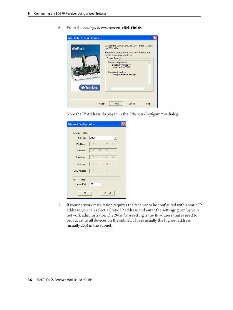
6. From the Settings Review screen, click Finish:
Note the IP Address displayed in the Ethernet Configuration dialog:
7. If your network installation requires the receiver to be configured with a static IP address, you can select a Static IP address and enter the settings given by your network administrator. The Broadcast setting is the IP address that is used to broadcast to all devices on the subnet. This is usually the highest address (usually 255) in the subnet.
36 BD970 GNSS Receiver Module User Guide

Configuring the BD970 Receiver Using a Web Browser 6
Configuring the receiver using a web browserThis section describes how to set up the receiver using a web browser.
Supported browsers
• Mozilla Firefox version 3.5 or later
• Microsoft Internet Explorer® internet browser version 7.00 or later for Windows operating systems
• Safari 4.0
• Opera 9
• Google Chrome
To connect to the receiver using a web browser:
1. Enter the IP address of the receiver into the address bar of the web browser as shown:
2. If security is enabled on the receiver, the web browser prompts you to enter a username and password:
The default login values for the receiver are:
– User Name: admin
– Password: password
If you cannot connect to the receiver, the password for the admin account may have been changed, or a different account may currently be in use. Contact your receiver administrator for the appropriate login information.
BD970 GNSS Receiver Module User Guide 37

6 Configuring the BD970 Receiver Using a Web Browser
Once you are logged in, the welcome web page appears, see Figure 6.1.
Figure 6.1 SPS GPS receiver Home webpage
Changing the settings
Use the webpage to configure the receiver settings. The web interface shows the configuration menus on the left of the browser window, and the settings on the right. Each configuration menu contains related submenus to configure the receiver and to monitor receiver performance.
Note – The configuration menus available vary based on the version of the receiver.
A summary of each configuration menu is provided here. For more detailed information about each of the receiver settings, select the Help menu. The Help is available whenever your computer is connected to the Internet. It is also available at any time from the Trimble website (www.trimble.com/OEM_ReceiverHelp/V3.60/en/).
To display the web interface in another language, click the corresponding country flag. The web interface is available in the following languages:
• English (en) • Italian (it)
• Chinese (zh) • Japanese (ja)
• Finnish ( fi) • Russian (ru)
• French ( fr) • Spanish (es)
• German (de) • Swedish (sv)
Receiver model name
Receiver serial number
Menus
Availablelanguages
38 BD970 GNSS Receiver Module User Guide

Configuring the BD970 Receiver Using a Web Browser 6
Receiver Status menu
The Receiver Status menu provides a quick link to review the receiver’s available options, current firmware version, IP address, temperature, runtime, satellites tracked, current outputs, available memory, position information, and more.
This figure shows an example of the screen that appears when you select Receiver Status / Identity :
BD970 GNSS Receiver Module User Guide 39

6 Configuring the BD970 Receiver Using a Web Browser
Satellites menu
Use the Satellites menu to view satellite tracking details and enable/disable GPS, GLONASS, and SBAS (WAAS/EGNOS/MSAS) satellites.
This figure shows an example of the screen that appears when you select Satellite / Tracking (Sky Plot):
40 BD970 GNSS Receiver Module User Guide

Configuring the BD970 Receiver Using a Web Browser 6
Receiver Configuration menu
Use the Receiver Configuration menu to configure such settings as elevation mask and PDOP mask, the antenna type and height, the reference station position, and the reference station name and code.
This figure shows an example of the screen that appears when you select Receiver Configuration / Summary :
BD970 GNSS Receiver Module User Guide 41

6 Configuring the BD970 Receiver Using a Web Browser
I/O Configuration menu
Use the I/O Configuration menu to set up all outputs of the receiver. The receiver can output CMR, RTCM, NMEA, GSOF, RT17, or BINEX messages. These messages can be output on TCP/IP, UDP, or serial ports.
This figure shows an example of the screen that appears when you select I/O Configuration / Port Summary :
42 BD970 GNSS Receiver Module User Guide

Configuring the BD970 Receiver Using a Web Browser 6
Internet Configuration menu
Use the Internet Configuration menu to configure Ethernet settings, email alerts, PPP connection, HTTP port, FTP port, and VFD port settings of the receiver. For information on the Ethernet settings, see Configuring Ethernet settings, page 34.
This figure shows an example of the screen that appears when you select Network Configuration / Ethernet:
BD970 GNSS Receiver Module User Guide 43

6 Configuring the BD970 Receiver Using a Web Browser
Security menu
Use the Security menu to configure the login accounts for all users who will be permitted to configure the receiver using a web browser. Each account consists of a username, password, and permissions. Administrators can use this feature to limit access to other users.
Security can be disabled for a receiver. However, Trimble discourages this as it makes the receiver susceptible to unauthorized configuration changes.
This figure shows an example of the screen that appears when you select Security / Configuration:
44 BD970 GNSS Receiver Module User Guide

Configuring the BD970 Receiver Using a Web Browser 6
Firmware menu
Use the Firmware menu to verify the current firmware and load new firmware to the receiver. You can upgrade firmware across a network or from a remote location without having to connect to the receiver with a serial cable.
This figure shows an example of the screen that appears when you select Firmware:
BD970 GNSS Receiver Module User Guide 45

6 Configuring the BD970 Receiver Using a Web Browser
Help Menu
The Help menu provides information on each of the receiver settings available in a web browser. Selecting the Help menu opens new windows. Select the section of the Help that you want to view. The Help files are stored on the Trimble Internet site (www.trimble.com/OEM_ReceiverHelp/V3.60/en/) and are updated between firmware releases.
Note – For languages other than English, replace en with the appropriate two-letter country code, see page 38
To access the Help, your computer must be connected to the Internet.
If you do not have access to the Internet, there is also a copy of the receiver Help files on the Trimble SPS GPS Receiver CD. (This copy shows the Help files as they were when the CD was published.)
This figure shows an example of the screen that appears when you select Help:
46 BD970 GNSS Receiver Module User Guide
Configuring the BD970 Receiver Using a Web Browser 6
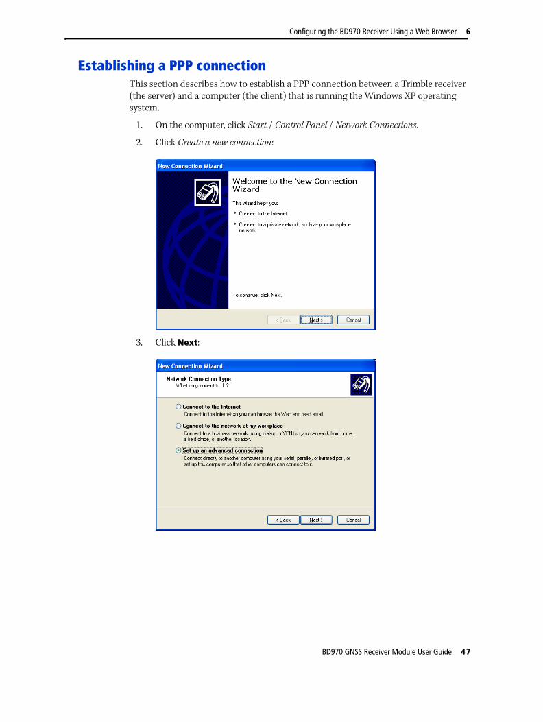
Establishing a PPP connectionThis section describes how to establish a PPP connection between a Trimble receiver (the server) and a computer (the client) that is running the Windows XP operating system.
1. On the computer, click Start / Control Panel / Network Connections.
2. Click Create a new connection:
3. Click Next:
BD970 GNSS Receiver Module User Guide 47

6 Configuring the BD970 Receiver Using a Web Browser
4. Select Set up an advanced connection. Click Next:
5. Select Connect directly to another computer. Click Next:
48 BD970 GNSS Receiver Module User Guide

Configuring the BD970 Receiver Using a Web Browser 6
6. Select Guest. Click Next:
7. Enter a meaningful name such as PPP to Trimble Receiver. Click Next:
BD970 GNSS Receiver Module User Guide 49

6 Configuring the BD970 Receiver Using a Web Browser
8. Select Communications cable between two computers (COM1). Click Next:
9. Select My use only. Click Next:
10. Select Add a shortcut to this connection to my desktop. Click Finish:
50 BD970 GNSS Receiver Module User Guide

Configuring the BD970 Receiver Using a Web Browser 6
11. Click Properties:
12. Click Configure:
13. Make sure that the Maximum speed (bps) is 38400, and that there is no flow control enabled. Click OK. (Or click Cancel if you did not make changes.)
Note – By default, Trimble receiver serial ports have baud rate: 38400, data bits: 8, parity: none, stop bits: 1, and flow control: none. If this default was changed on the receiver, this setting should match it.
BD970 GNSS Receiver Module User Guide 51

6 Configuring the BD970 Receiver Using a Web Browser
14. In the PPP Trimble Receiver Properties dialog, select the Networking tab:
15. Select Internet Protocol (TCP/IP) and then click Properties:
52 BD970 GNSS Receiver Module User Guide

Configuring the BD970 Receiver Using a Web Browser 6
16. Click Advanced:
17. Clear the Use default gateway on remote network check box. Click OK one or more times until the Connect PPP to Trimble Receiver dialog appears:
18. If the serial port has a serial cable connected to the receiver, click Connect. You do not need to enter a User name or Password.
BD970 GNSS Receiver Module User Guide 53

6 Configuring the BD970 Receiver Using a Web Browser
On the bottom right of the computer screen, you will see the PPP to Trimble Receiver network connection icon:
19. Right-click the icon and then select Status:
20. Select the Details tab:
The Server IP address (192.168.100.110) is the address to access the receiver.
54 BD970 GNSS Receiver Module User Guide

Configuring the BD970 Receiver Using a Web Browser 6
21. Open a Web browser and then enter the Server IP address in the address field:
22. If security is enabled on the board, enter the default User name: admin and Password: password. Click OK:
The receiver and computer are connected.
Trimble recommends that you run the receiver and the computer at 115 k baud to speed up screen views.
BD970 GNSS Receiver Module User Guide 55

6 Configuring the BD970 Receiver Using a Web Browser
56 BD970 GNSS Receiver Module User Guide
C H A P T E R
7
Configuring the BD970 Receiver Using Binary Interface Commands 7In this chapter:
RS-232 Serial Interface Specification
Data Collector Format Command Packets
Data Collector Format Report Packets
This chapter documents the Data Collector Format packets that are used to configure the receiver settings and outputs.
BD970 GNSS Receiver Module User Guide 57

7 Configuring the BD970 Receiver Using Binary Interface Commands
RS-232 Serial Interface SpecificationThe RS-232 Serial Interface Specification enables a remote computing device to communicate with a BD970 receiver over an RS-232 connection, using Data Collector Format packets. The RS-232 Serial Interface Specification provides command packets for configuring the BD970 receiver for operation, and report packets for retrieving position and status information from the receiver.
Data Collector Format packets are similar to the data collector format packets which evolved with the Trimble Series 4000 receivers. The set of Data Collector Format command and report packets implemented on the receiver are simplified with a more flexible method for scheduling the output of data. For a detailed explanation of the streamed data output format, see 40h, GENOUT (General output record reports), page 92.
The receiver is configured for operation using application files. Application files include fields for setting all receiver parameters and functions. The default application file for the receiver includes the factory default values. Multiple application files can be transferred to the receiver for selection with command packets. Application files for specific applications can be developed on one receiver and downloaded to a computer for transfer to other BD970 receivers.
For a general description of application files, see To send application files to the receiver, use the Trimble Configuration Toolbox software or create the application files with a custom software program., page 68. For information about the structure of application files, see 64h, APPFILE (Application file record command), page 68.
Communications format
Supported data rates are: 2400, 4800, 9600, 19200, 38400, and 57600 baud and 115 kbaud. Any of these data rates can be used, however only 4800 baud or higher should be used. For example, a 20 Hz GGK string output requires the baud rate to be set to at least 19200. Only an 8-bit word format is supported, with Odd, Even, or No parity, and 1 stop bit. The default communications format for the receiver is 38400 baud, 8 data bits, no parity, and 1 stop bit.
Changes to the serial format parameter settings for all serial ports are stored in EEPROM (Electrically-Erasable Read-Only Memory) and remain in effect across power cycles until you change the parameter settings.
58 BD970 GNSS Receiver Module User Guide

Configuring the BD970 Receiver Using Binary Interface Commands 7
Testing the communications link
To determine whether the receiver can accept RS-232 commands, the protocol request ENQ (05h) is used. The response is either ACK (06h) or NAK (15h).
ENQ/ACK/NAK correspond to “Are you ready?”, “I am ready”, and “I am not ready”. This quick 1-byte test can be sent by the remote device before any other command to make sure that the RS-232 line is clear and operational.
Communication errors
The receiver normally responds to a RS-232 Serial Interface Specification command packet within 500 milliseconds. If the receiver does not respond to the request or command, the external device can send numerous \0 characters (250) to cancel any partially received message before resending the previous message.
Data Collector Format packets
Command packets are sent from the remote device to the BD970 receiver when requesting data, sending commands, or when managing application files. The BD970 receiver acknowledges every command packet sent by the remote device. It does this by sending an associated report packet or by acknowledging the transaction with an ACK (06h) or NAK (15h) from the receiver.
Note – The return of a NAK sometimes means that the receiver cannot fulfill the request. That is, the requested command is not supported.
Packets are processed by the receiver on a first-in, first-out (FIFO) basis. External devices can send multiple packets without waiting for a response from each packet. The external device is responsible for matching expected responses with the actual response sent by the receiver.
Each message begins with a 4-byte header, followed by the bytes of data in the packet, and the packet ends with a 2-byte trailer. Byte 3 is set to 0 (00h) when the packet contains no data. Most data is transmitted between the receiver and remote device in binary format.
BD970 GNSS Receiver Module User Guide 59

7 Configuring the BD970 Receiver Using Binary Interface Commands
Data Collector Format packet structure
Every command and report packet, regardless of its source and except for protocol sequences, has the same format as shown in Table 7.1.
Data Collector Format packet functions
C WARNING – Virtually no range checking is performed by the receiver on the values supplied by the remote device. The remote device must adhere to the exact ranges specified within this document. Failure to do so can result in a receiver crash and/or loss of data.
The functions of Data Collector Format command and report packets can be divided into the following categories:
• Information requests (command packets) and replies (report packets)
• Control functions (command packets) and RS-232 acknowledgments (ACK or NAK)
• Application file management
Requests for information, such as the Command Packet 4Ah (GETOPT), can be sent at any time. The expected reply (Report Packet 4Bh, RETOPT) is always sent. Some control functions may result in an RS-232 acknowledgment of NAK (15h) if one of the following conditions exists:
• The request is not supported (invalid) by the receiver ( for example, a required option may not be installed on the receiver).
• The receiver cannot process the request.
Table 7.1 Data Collector Format packet structure
Byte # Message Description
Begin packet header
0 STX (02h) Start transmission
1 STATUS Receiver status code (see Table 7.2)
2 PACKET TYPE Hexadecimal code assigned to the packet
3 LENGTH Single byte # of data bytes, limits data to 255 bytes
Begin packet data
4 to length DATA BYTES Data bytes
Begin packet trailer
Length + 4 CHECKSUM (status + type + length + data bytes) modulo 256
Length + 5 ETX (03h) End transmission
60 BD970 GNSS Receiver Module User Guide

Configuring the BD970 Receiver Using Binary Interface Commands 7
The receiver STATUS byte
The status byte contains important indicators that usually require immediate attention by the remote device. The receiver never makes a request of the remote device. Each bit of the status byte identifies a particular problem. More than one problem may be indicated by the status byte. Table 7.2 lists the status byte codes.
Reading binary values
The receiver stores numbers in Motorola format. The byte order of these numbers is the opposite of what personal computers expect (Intel format). To supply or interpret binary numbers (8-byte DOUBLES, 4-byte LONGS, and 2-byte INTEGERS), the byte order of these values must be reversed. A detailed description of the Motorola format used to store numbers in the receiver is provided in the following sections.
Table 7.2 Status byte codes
Bit Bit value Meaning
Bit 0 1 Reserved
Bit 1 1 Low battery
Bit 2–7 0–63 Reserved
BD970 GNSS Receiver Module User Guide 61

7 Configuring the BD970 Receiver Using Binary Interface Commands
INTEGER data types
The INTEGER data types (CHAR, SHORT, and LONG) can be signed or unsigned. They are unsigned by default. All integer data types use two’s complement representation. Table 7.3 lists the integer data types.
FLOATING-POINT data types
Floating-point data types are stored in the IEEE SINGLE and DOUBLE precision formats. Both formats have a sign bit field, an exponent field, and a fraction field. The fields represent floating-point numbers in the following manner:
Floating-Point Number = <sign> 1.<fraction field> x 2 (<exponent field> - bias)
• Sign bit field
The sign bit field is the most significant bit of the floating-point number. The sign bit is 0 for positive numbers and 1 for negative numbers.
• Fraction field
The fraction field contains the fractional part of a normalized number. Normalized numbers are greater than or equal to 1 and less than 2. Since all normalized numbers are of the form 1.XXXXXXXX, the 1 becomes implicit and is not stored in memory. The bits in the fraction field are the bits to the right of the binary point, and they represent negative powers of 2.
For example:
0.011 (binary) = 2-2 + 2-3 = 0.25 + 0.125 = 0.375
• Exponent field
The exponent field contains a biased exponent; that is, a constant bias is subtracted from the number in the exponent field to yield the actual exponent. (The bias makes negative exponents possible.)
If both the exponent field and the fraction field are zero, the floating-point number is zero.
• NaN
A NaN (Not a Number) is a special value that is used when the result of an operation is undefined. For example, adding positive infinity to negative infinity results in a NaN.
Table 7.3 Integer data types
Type # of bits Range of values (Signed) (Unsigned)
CHAR 8 –128 to 127 0 to 255
SHORT 16 –32768 to 32767 0 to 65535
LONG 32 –2147483648 to 2147483647 0 to 4294967295
62 BD970 GNSS Receiver Module User Guide

Configuring the BD970 Receiver Using Binary Interface Commands 7
FLOAT data type
The FLOAT data type is stored in the IEEE single-precision format which is 32 bits long. The most significant bit is the sign bit, the next 8 most significant bits are the exponent field, and the remaining 23 bits are the fraction field. The bias of the exponent is 127. The range of single-precision format values is from 1.18 × 10–38 to 3.4 × 1038. The floating-point number is precise to 6 decimal digits.
0 000 0000 0 000 0000 0000 0000 0000 0000 = 0.00 011 1111 1 000 0000 0000 0000 0000 0000 = 1.01 011 1111 1 011 0000 0000 0000 0000 0000 = -1.3751 111 1111 1 111 1111 1111 1111 1111 1111 = NaN
DOUBLE
The DOUBLE data type is stored in the IEEE double-precision format which is 64 bits long. The most significant bit is the sign bit, the next 11 most significant bits are the exponent field, and the remaining 52 bits are the fractional field. The bias of the exponent is 1023. The range of single precision format values is from 2.23 x 10–308 to 1.8 x 10308. The floating-point number is precise to 15 decimal digits.
0 000 0000 0000 0000 0000 ... 0000 0000 0000 = 0.00 011 1111 1111 0000 0000 ... 0000 0000 0000 = 1.01 011 1111 1110 0110 0000 ... 0000 0000 0000 = -0.68751 111 1111 1111 1111 1111 ... 1111 1111 1111 = NaN
S Exp. + Bias Fraction
31 30 23 22 0
S Exp. + Bias Fraction
63 62 52 51 0
BD970 GNSS Receiver Module User Guide 63

7 Configuring the BD970 Receiver Using Binary Interface Commands
Data Collector Format Command PacketsData Collector Format command packets are sent from the remote device to the receiver to execute receiver commands or to request data reports. The receiver acknowledges all command packets. It does this by sending a corresponding report packet or by acknowledging the completion of an action.
The following sections provide details for each command and report packet. Table 7.4 provides a summary of the command packets.
Table 7.4 Command Packet summary
ID, Command Packet Action Page
06h, GETSERIAL (Receiver and antenna information request)
06h, GETSERIAL (Receiver and antenna information request)
68
54h, GETSVDATA (Satellite information request)
54h, GETSVDATA (Satellite information request) 66
56h, GETRAW (Position or real-time survey data request)
56h, GETRAW (Position or real-time survey data request)
67
64h, APPFILE (Application file record command)
64h, APPFILE (Application file record command) 68
65h, GETAPPFILE (Application file request) 65h, GETAPPFILE (Application file request) 82
66h, GETAFDIR (Application file directory listing request)
66h, GETAFDIR (Application file directory listing request)
83
68h, DELAPPFILE (Delete application file data command)
68h, DELAPPFILE (Delete application file data command)
84
6Dh, ACTAPPFILE (Activate application file) 6Dh, ACTAPPFILE (Activate application file) 85
81h, KEYSIM (Key simulator) 81h, KEYSIM (Key simulator) 86
82h, SCRDUMP (Screen dump request) 82h, SCRDUMP (Screen dump request) 88
64 BD970 GNSS Receiver Module User Guide

Configuring the BD970 Receiver Using Binary Interface Commands 7
06h, GETSERIAL (Receiver and antenna information request)
Command Packet 06h requests receiver and antenna information. The receiver responds by sending the data in the Report Packet 07h:
Table 7.5 describes the packet structure.
Packet flow
Receiver Remote
← Command Packet 06h
Report Packet 07h →
Table 7.5 Command packet 06h structure
Byte # Item Type Value Meaning
0 STX CHAR 02h Start transmission
1 STATUS CHAR See Table 7.2, page 61 Receiver status code
2 PACKET TYPE CHAR 06h Command Packet 06h
3 LENGTH CHAR 00h Data byte count
4 CHECKSUM CHAR See Table 7.1, page 60 Checksum value
5 ETX CHAR 03h End transmission
BD970 GNSS Receiver Module User Guide 65

7 Configuring the BD970 Receiver Using Binary Interface Commands
54h, GETSVDATA (Satellite information request)
Command Packet 54h requests satellite information. The request may be for an array of flags showing the availability of satellite information such as an ephemeris or almanac. In addition, satellites may be enabled or disabled with this command packet. Table 7.6 shows the packet structure. For additional information, see Data Collector Format packet structure, page 60.
Note – The normal reply to Command Packet 54h is usually Report Packet 55h. However, a NAK is returned if the SV PRN is out of range (except for SV FLAGS), if the DATA SWITCH parameter is out of range, or if the requested data is not available for the designated SV.
Packet Flow
Receiver Remote
← Command Packet 54h
Report Packet 55h or NAK →
Table 7.6 Command packet 54h structure
Byte # Item Type Value Meaning
0 STX CHAR 02h Start transmission
1 STATUS CHAR 00h Receiver status code
2 PACKET TYPE CHAR 54h Command Packet 54h
3 LENGTH CHAR 03h Data byte count
4 DATA SWITCH CHAR See Table 7.7, page 66 Selects type of satellite information downloaded from receiver or determines whether a satellite is enabled or disabled
5 SV PRN # CHAR 01h–20h Pseudorandom number (1–32) of satellite (ignored if SV Flags or ION/UTC is requested)
6 RESERVED CHAR 00h Reserved (set to zero)
7 CHECKSUM CHAR See Table 7.2, page 61 Checksum value
8 ETX CHAR 03h End transmission
Table 7.7 DATA SWITCH byte values
Byte value Meaning
Dec Hex
0 00h SV Flags indicating Tracking, Ephemeris and Almanac, Enable/Disable state
1 01h Ephemeris
2 02h Almanac
3 03h ION/UTC data
4 04h Disable Satellite
5 05h Enable Satellite
The Enable and Disable Satellite data switch values always result in the transmission of a RETSVDATA message as if the SV Flags are being requested.
66 BD970 GNSS Receiver Module User Guide

Configuring the BD970 Receiver Using Binary Interface Commands 7
56h, GETRAW (Position or real-time survey data request)
Command Packet 56h requests raw satellite data in *.DAT Record 17 format or Concise format. The request may specify if Real-Time attribute information is required. The receiver responds by sending the data in Report Packet 57h. Alternatively, the packet can be used to request receiver position information in *.DAT record 11 format. Table 7.8 describes the packet structure. For additional information, see 57h, RAWDATA (Position or real-time survey data report), page 126.
Note – The reply to this command packet is usually a Report Packet 57h. A NAK is returned if the Real-Time Survey Data Option (RT17) is not installed on the receiver.
Packet Flow
Receiver Remote
← Command Packet 56h
Report Packet 57h or NAK →
Table 7.8 Command packet 56h structure
Byte # Item Type Value Meaning
0 STX CHAR 02h Start transmission
1 STATUS CHAR See Table 7.2, page 61 Receiver status code
2 PACKET TYPE CHAR 56h Command Packet 56h
3 LENGTH CHAR 03h Data byte count
4 TYPE RAW DATA CHAR See Table 7.9, page 67 Identifies the requested type of raw data
5 FLAGS CHAR See Table 7.10, page 67 Flag bits for requesting raw data
6 RESERVED CHAR 00h Reserved; set to zero
7–8 CHECKSUM SHORT See Table 7.1, page 60 Checksum value
9 (03h) ETX CHAR 03h End transmission
Table 7.9 TYPE RAW DATA values
Byte value Meaning
Dec Hex
0 00h Real-Time Survey Data Record (Record Type 17)
1 01h Position Record (Record Type 11)
Table 7.10 FLAGS bit values
Bit Meaning
0 Raw Data Format
0: Expanded *.DAT Record Type 17 format
1: Concise *.DAT Record Type 17 format
1 Enhanced Record with real-time flags and IODE information
0: Disabled – record data not enhanced
1: Enabled – record data is enhanced
2–7 Reserved (set to zero)
BD970 GNSS Receiver Module User Guide 67

7 Configuring the BD970 Receiver Using Binary Interface Commands
64h, APPFILE (Application file record command)
To send application files to the receiver, use the Trimble Configuration Toolbox software or create the application files with a custom software program.
Application files contain a collection of individual records that fully prescribe the operation of the receiver. Application files are transferred using the standard Data Collector Format packet format.
Each application file can be tailored to meet the requirements of separate and unique applications. Up to 10 application files can be stored within the receiver for activation at a later date.
The two important application files in the receiver are explained in Table 7.11.
Individual records within an existing application file can be updated using the software tools included with the receiver. For example, the OUTPUT MESSAGES record in an application file can be updated without affecting the parameter settings in other application file records.
Application files can be started immediately and/or the files can be stored for later use.
Once applications files are transferred into memory, command packets can be used to manage the files. Command packets are available for transferring, selecting, and deleting application files.
If any part of the application record data is invalid, then the receiver ignores the entire record. The receiver reads a record using the embedded length. Any extraneous data is ignored. This allows for backward compatibility when the record length is increased to add new functions.
If you are concerned about application files producing the same results on future receivers, make sure that the application records do not contain extraneous data.
Command Packet 64h is sent to create, replace, or report on an application file. The command packet requests the application file by System File Index.
For detailed information about BD970 Application Files and for guidelines about using application files to control remote devices, see Report Packet 64h, APPFILE (Application file record report), page 135.
Table 7.11 Important application files and their functions
Name Function
DEFAULT Permanently stored application file containing the receiver’s factory default settings. This application file is used when the receiver is reset to the factory default settings.
CURRENT Holds the current settings of the receiver.
Packet Flow
Receiver Remote
← Command Packet 64h
ACK →
68 BD970 GNSS Receiver Module User Guide

Configuring the BD970 Receiver Using Binary Interface Commands 7
Packet paging
Since an application file contains a maximum of 2048 bytes (all records are optional) of data and exceeds the byte limit for RS-232 Serial Interface Specification packets, Command Packet 64h is divided into several subpackets called pages. The PAGE INDEX byte (byte 5) identifies the packet page number and the MAXIMUM PAGE INDEX byte (byte 6) indicates the maximum number of pages in the report.
The first and subsequent pages are filled with a maximum of 248 bytes consisting of 3 bytes of page information and 245 bytes of application file data. The application file data is split wherever the 245 byte boundary falls. Therefore the remote device sending the Command Packet pages must construct the application file using the 248 byte pages before sending the file to the receiver.
To prevent data mismatches, each report packet is assigned a Transmission Block Identifier (byte 4) which gives the report pages a unique identity in the data stream. The software on the remote device can identify the pages associated with the report and reassemble the application file using bytes 4–6.
Table 7.12 shows the structure of the report packet containing the application file.
Table 7.12 Command packet 64h structure
Byte # Item Type Value Meaning
0 STX CHAR 02h Start transmission.
1 STATUS CHAR 00h Receiver status code.
2 PACKET TYPE CHAR 64h Command Packet 64h.
3 LENGTH CHAR 00h Data byte count.
4 TX BLOCK IDENTIFIER CHAR 00h–FFh A Transmission Block Identifier, ranging between 0–255, that must remain the same for all pages of an application file transfer.
5 PAGE INDEX CHAR 00h–FFh Index number (0–255) assigned to the current page.
6 MAXIMUM PAGE INDEX
CHAR 00h–FFh Index number (0–255) assigned to the last page of the packet.
FILE CONTROL INFORMATION BLOCK
The FILE INFORMATION CONTROL BLOCK must be sent in the first page of the report containing the application file. The second page and consecutive pages must not include a FILE CONTROL INFORMATION BLOCK.
7 APPLICATION FILE SPECIFICATION VERSION
CHAR 03h Always 3 for this version of the specification.
8 DEVICE TYPE CHAR See Table 7.13, page 73 Unique identifier for every receiver/device type that supports the application file interface.
9 START APPLICATION FILE FLAG
CHAR See Table 7.14, page 73 Determines whether the application file is activated immediately after records are sent to receiver.
10 FACTORY SETTINGS FLAG
CHAR See Table 7.15, page 73 Determines whether the receiver is reset to factory default settings before activating the records in the application file.
BD970 GNSS Receiver Module User Guide 69

7 Configuring the BD970 Receiver Using Binary Interface Commands
Insert Appfile Records here. (See Below)
Length +4
CHECKSUM CHAR See Table 7.1, page 60 Checksum value.
Length +5
ETX CHAR 03h End transmission.
APPLICATION FILE RECORDS
The records listed below (for example, FILE STORAGE RECORD, GENERAL CONTROLS RECORD) are subtypes of the FILE CONTROL INFORMATION BLOCK.
FILE STORAGE RECORD
The FILE STORAGE RECORD indicates the application file creation date and time and provides identification information required to store the file in memory. When included in the application file, this record must be the first record within the file.
0 RECORD TYPE CHAR 00h File Storage Record.
1 RECORD LENGTH CHAR 0Dh Number of bytes in record, excluding bytes 0 and 1.
2–9 APPLICATION FILE NAME
CHARs ASCII textA...Z, a...z,_ (underscore)
Eight-character name for the application file.
10 YEAR OF CREATION CHAR 00h–FFh Year when application file is created, ranging from 00–255 (1900 = 00).
11 MONTH OF CREATION
CHAR 01h–0Ch Month when application file is created (01–12).
12 DAY OF CREATION CHAR 00h–1Fh Day of the month when application file is created (00–31).
13 HOUR OF CREATION CHAR 00h–17h Hour of the day when application file is created (00-23).
14 MINUTES OF CREATION
CHAR 00h–3Bh Minutes of the hour when application file is created (00–59).
GENERAL CONTROLS RECORD
The GENERAL CONTROLS RECORD sets general GPS operating parameters for the receiver, including the elevation mask, measurement rate, PDOP (Position Dilution of Precision) mask, and the positioning mode.
0 RECORD TYPE CHAR 01h General controls record.
1 RECORD LENGTH CHAR 08h Number of bytes in record, excluding bytes 0 and 1.
2 ELEVATION MASK CHAR 00h–5Ah Elevation mask in degrees (0–90).
3 MEASUREMENT RATE CHAR See Table 7.16, page 74 Frequency rate at which the receiver generates measurements.
4 PDOP MASK CHAR 00h–FFh Position Dilution of Precision mask (0–255).
5 RESERVED CHAR 00h Reserved (set to zero).
6 RESERVED CHAR 00h Reserved (set to zero).
7 RTK POSITIONING MODE
CHAR See Table 7.20, page 75 Sets the RTK positioning mode.
8 POSITIONING SOLUTION SELECTION
CHAR See Table 7.17, page 74 Controls use of DGPS and RTK solutions.
Table 7.12 Command packet 64h structure (continued)
Byte # Item Type Value Meaning
70 BD970 GNSS Receiver Module User Guide

Configuring the BD970 Receiver Using Binary Interface Commands 7
9 RESERVED CHAR 00h Reserved (set to zero).
SERIAL PORT BAUD/FORMAT RECORD
The SERIAL PORT BAUD RATE/FORMAT RECORD is used to set the communication parameters for the serial ports. Individual serial ports are identified within the record by the SERIAL PORT INDEX number.
0 RECORD TYPE CHAR 02h Serial Port Baud Rate/Format Record.
1 RECORD LENGTH CHAR 04h Number of bytes in the record, excluding bytes 0 and 1.
2 SERIAL PORT INDEX. CHAR 00h–03h The number of the serial port to configure.
3 BAUD RATE CHAR See Table 7.18, page 74 Data transmission rate.
4 PARITY CHAR See Table 7.19, page 74 Sets the parity of data transmitted through the port. The eight data bits and one stop bit are always used, regardless of the parity selection.
5 FLOW CONTROL CHAR See Table 7.21, page 75 Flow control.
REFERENCE (BASE) NODE RECORD
The REFERENCE NODE RECORD is an optional record for providing LLA (Latitude, Longitude, Altitude) coordinates for base station nodes.
0 RECORD TYPE CHAR 03h Reference Node Record.
1 RECORD LENGTH CHAR 25h Data bytes in the record, excluding bytes 0 and 1.
2 FLAG CHAR 00h Reserved (set to zero).
3 NODE INDEX CHAR 00h Reserved (set to zero).
4–11 NAME CHAR ASCII text Eight-character reference node description.
12–19 REFERENCE LATITUDE DOUBLE radians Latitude of reference node, ±π/2.
20–27 REFERENCE LONGITUDE
DOUBLE radians Longitude of reference node, ± π.
28–35 REFERENCE ALTITUDE DOUBLE meters Altitude of reference node, –9999.999 ≤ h ≤ +9999.999.
36–37 STATION ID SHORT 0000h–03FFh Reference Node Station ID for RTCM output.
38 RTK STATION CHAR 00h–1Fh Reference Station ID for RTK output.
SV ENABLE/DISABLE RECORD
The SV ENABLE/DISABLE RECORD is used to enable or disable a selection of the 32 GPS satellites. By default, the receiver is configured to use all satellites which are in good health. This record is useful for enabling satellites which are not in good health. Once enabled, the health condition of the satellite(s) is ignored, and the GPS signal transmissions from the satellite(s) are considered when computing position solutions.
0 RECORD TYPE CHAR 06h SV Enable/Disable Record.
1 RECORD LENGTH CHAR 20h Number of bytes in record, excluding bytes 0 and 1.
2–33 SV ENABLE/DISABLE STATES
CHARs See Table 7.22, page 75 Array of Enable/Disable flags for the 32 SVs. The first byte sets the required Enable/Disable status of SV1, the second sets the status of SV2, etc.
Table 7.12 Command packet 64h structure (continued)
Byte # Item Type Value Meaning
BD970 GNSS Receiver Module User Guide 71

7 Configuring the BD970 Receiver Using Binary Interface Commands
OUTPUT MESSAGE RECORD
The OUTPUT MESSAGE RECORD selects the outputs for a specified serial port, the frequency of message transmissions, the integer second offset from the scheduled output rate, and output specific flags. Bytes 0 through 5 are included in all records, regardless of the output message type. The remaining bytes in the record (byte 6...) are dependent on the output message type.
0 RECORD TYPE CHAR 07h Output Message Record.
1 RECORD LENGTH CHAR 04h, 05h or 06h Number of bytes in the record, excluding bytes 0 and 1. The number of bytes is dependent on the number of output specific flags.
2 OUTPUT MESSAGE TYPE
CHAR See Table 7.23, page 75 Type of message or packet.
3 PORT INDEX CHAR 00h–03h Serial port index number.
4 FREQUENCY CHAR See Table 7.24, page 77 Frequency of message transmissions.
5 OFFSET CHAR 00h–FFh Integer second offset (0–255 seconds) from scheduled output rate. (Only valid when frequency is < 1 Hz or >1 second.)
Note – The remaining bytes depend on the output message type (Byte 2). One or two flag bytes can be sent, but two are always stored in the receiver.
OUTPUT MESSAGE RECORD TYPE 10 (GSOF)
6 GSOF SUBMESSAGE TYPE
CHARs See Table 7.32, page 81 GSOF message number.
7 OFFSET CHAR 0–255 Integer second offset from scheduled frequency.
OUTPUT MESSAGE RECORD TYPE 2 (RTK-CMR)
6 CMR MESSAGE TYPE FLAGS
CHAR See Table 7.25, page 77 CMR message types.
OUTPUT MESSAGE RECORD TYPE 3 (RTCM)
6 RTCM FLAGS CHAR See Table 7.27, page 78 Bit settings for RTCM output flags.
OUTPUT MESSAGE RECORD TYPE 4 (RT17)
6 REAL-TIME 17 MESSAGE FLAGS
CHAR See Table 7.26, page 78 RT17 (Real Time 17) flags.
ANTENNA RECORD
The ANTENNA RECORD identifies the Antenna Type and the true vertical height of antenna above the ground mark.
0 RECORD TYPE CHAR 08h Reference Node record.
1 RECORD LENGTH CHAR 0Ch Number of bytes in record, excluding bytes 0 and 1.
2–9 ANTENNA HEIGHT DOUBLE meters Vertical height of antenna, in meters.
10–11 ANTENNA TYPE SHORT See Table 7.28, page 79 Defines the type of antenna connected to the receiver.
12 RESERVED CHAR 00h Reserved (set to zero).
13 RESERVED CHAR 00h Reserved (set to zero).
Table 7.12 Command packet 64h structure (continued)
Byte # Item Type Value Meaning
72 BD970 GNSS Receiver Module User Guide

Configuring the BD970 Receiver Using Binary Interface Commands 7
DEVICE CONTROL RECORD
The DEVICE CONTROL RECORD contains configuration parameters for controlling some external devices and the operation of some receiver options. The number of bytes contained in the record and the length of the record are determined by the DEVICE TYPE entry. The table subheadings identify different devices
0 RECORD TYPE CHAR 09h Device Control record.
1 RECORD LENGTH CHAR 02h or 0Dh Number of bytes in record, excluding bytes 0 and 1.
2 DEVICE TYPE CHAR See Table 7.29, page 80 Type of device.
For 1 PPS Output Only
3 1 PPS CONTROL CHAR See Table 7.30, page 80 Enables or disables 1 PPS output; byte 2 is set to 2.
STATIC/KINEMATIC RECORD
The bytes value in the STATIC/KINEMATIC RECORD determine whether the receiver is operating in Static or Kinematic mode.
0 RECORD TYPE CHAR 0Ah Static/Kinematic record.
1 RECORD LENGTH CHAR 01h Number of bytes in record, excluding bytes 0 and 1.
2 STATIC/KINEMATIC MODE
CHAR See Table 7.31, page 80 Configures receiver for static or kinematic operation.
Table 7.13 DEVICE TYPE byte values
Byte value Meaning
Dec Hex
0 00h All Devices
2–5 02h–05h Reserved
66 42h BD970 receiver
Table 7.14 START APPLICATION FILE FLAG byte values
Byte value Meaning
Dec Hex
0 00h Do not apply the application file parameter settings to the active set of parameters when the transfer is complete.
1 01h Apply application file records immediately.
Table 7.15 FACTORY SETTINGS byte values
Byte value Meaning
Dec Hex
0 00h Alter receiver parameters only as specified in the application file. Leave unspecified settings alone.
1 01h Set all controls to factory settings prior to applying the application file.
Table 7.12 Command packet 64h structure (continued)
Byte # Item Type Value Meaning
BD970 GNSS Receiver Module User Guide 73

7 Configuring the BD970 Receiver Using Binary Interface Commands
Table 7.16 MEASUREMENT RATE byte values
Byte value Meaning
Dec Hex
0 00h 1 Hz
1 01h 5 Hz
2 02h 10 Hz
Table 7.17 POSTITIONING SOLUTION SELECTION values
Byte value Meaning
Dec Hex
0 00 Use best available solution.
1 01 Produce DGPS and Autonomous solutions.
2 02 Produce DGPS, RTK Float, and Autonomous solutions. On-the-fly RTK initialization is disabled, therefore no RTK Fix solutions are generated.
3 03 Produce RTK Fix, DGPS, and Autonomous solutions (no RTK Float solutions).
Table 7.18 BAUD RATE byte values
Byte value Meaning
Dec Hex
0 00h 9600 baud (default)
1 01h 2400 baud
2 02h 4800 baud
3 03h 9600 baud
4 04h 19.2K baud
5 05h 38.4K baud
6 06h 57.6K baud
7 07h 115.2K baud
8 08h 300 baud
9 09h 600 baud
10 0Ah 1200 baud
11 0Bh 230,000 baud
12 0Ch 460,000 baud
Table 7.19 PARITY byte values
Byte value Meaning
Dec Hex
0 00h No Parity (10-bit format)
1 01h Odd Parity (11-bit format)
2 02h Even Parity (11-bit format)
74 BD970 GNSS Receiver Module User Guide

Configuring the BD970 Receiver Using Binary Interface Commands 7
Table 7.20 RTK POSITIONING MODE byte values
Byte value Meaning
Dec Hex
0 00h Synchronous positioning
1 01h Low Latency positioning
Table 7.21 FLOW CONTROL byte values
Byte value Meaning
Dec Hex
0 00h None
1 01h CTS
Table 7.22 SV ENABLE/DISABLE STATES flag values
Byte value Meaning
Dec Hex
0 00h Heed health (default)
1 01h Disable the satellite
2 02h Enable the satellite regardless of whether the satellite is in good or bad health
Table 7.23 OUTPUT MESSAGE TYPE byte values
Byte value Meaning
0xFF Turn off all outputs on all ports. Frequency must also be 'Off' for this to work.
0 Turn off all outputs on the given port only. Frequency must be 'Off' for this to work
1 Not used.
2 CMR Output
3 RTCM Output
4 RT17 Output
5 Not used.
6 NMEA_GGA
7 NMEA_GGK
8 NMEA_ZDA
9 Reserved
10 GSOF
11 1PPS
12 NMEA_VTG
13 NMEA_GST
14 NMEA_PJK
15 NMEA_PJT
16 NMEA_VGK
BD970 GNSS Receiver Module User Guide 75

7 Configuring the BD970 Receiver Using Binary Interface Commands
17 NMEA_VHD
18 NMEA_GSV
19 NMEA_TSN
20 NMEA_TSS
21 NMEA_PRC
22 NMEA_REF
23 NMEA_GGK_SYNC
24 J1939_VehPos
25 J1939_Time
26 J1939_VehSpd
27 J1939_ImpPos
28 J1939_ImpSpd
29 NMEA_AVR
30 Reserved
31 NMEA_HDT
32 NMEA_ROT
33 NMEA_ADV
34 NMEA_PIO
35 NMEA_BETA
36 Reserved
37 NMEA_VRSGGA
38 NMEA_GSA
39 Binex
40 NMEA_RMC
41 NMEA_BPQ
42 Reserved
43 Reserved
44 NMEA_GLL
45 NMEA_GRS
46 Reserved
47 NMEA_LDG
Table 7.23 OUTPUT MESSAGE TYPE byte values (continued)
Byte value Meaning
76 BD970 GNSS Receiver Module User Guide

Configuring the BD970 Receiver Using Binary Interface Commands 7
Table 7.24 FREQUENCY byte values
Byte value Meaning
Dec Hex
0 00h Off
1 01h 10 Hz
2 02h 5 Hz
3 03h 1 Hz
4 04h 2 seconds
5 05h 5 seconds
6 06h 10 seconds
7 07h 30 seconds
8 08h 60 seconds
9 09h 5 minutes
10 0Ah 10 minutes
11 0Bh 2 Hz
12 0Ch 15 seconds
13 0Dh 20 Hz
15 0Fh 50 Hz
255 FFh Once only, immediately
Certain message output types may not support >1 Hz output.
Table 7.25 CMR MESSAGE TYPE byte values
Byte value Meaning
Dec Hex
0 00h Standard (CMR, CMR+™).
1 01h High speed CMR (5 or 10 Hz).
2 02h Compatible with Trimble 4000 receivers.
BD970 GNSS Receiver Module User Guide 77

7 Configuring the BD970 Receiver Using Binary Interface Commands
If Flags are invalid, the record is not applied. (However, the Appfile may be accepted.)
Table 7.26 REAL-TIME 17 MESSAGE bit values
Bit Meaning
7 (msb) Reserved (set to zero)
6 Reserved (set to zero)
5 Reserved (set to zero)
4 Position Only
0: Disabled
1: Enabled
3 Streamed Position
0: Disabled
1: Enabled
2 Streamed Ephemeris
0: Disabled
1: Enabled
1 RT (Real-Time) Enhancements
0: Disabled
1: Enabled
0 (lsb) Compact Format
0: Disabled
1: Enabled
Table 7.27 RTCM Flag bit values
Bit Meaning
0 Invalid value
1 Output RTK RTCM packets (Type 18 & 19)
2 Output DGPS RTCM packets (Type 1)
3 Output RTK and DGPS RTCM packets (Types 1, 18, and 19)
4 Output Type 9 Groups of 3
Bit 3 (Use RTCM version 2.2)
0: Off
1: On
(Multiple message bit turned on in Types 18 and 19)
Bit 4 (Use RTCM version 2.3)
0: Off
1: On
(Output Types 23 & 24)
5–7 Invalid values
78 BD970 GNSS Receiver Module User Guide

Configuring the BD970 Receiver Using Binary Interface Commands 7
Table 7.28 ANTENNA TYPE byte values
Byte value Meaning
Dec Hex
0 00h Unknown External
1 01h 4000ST Internal
2 02h 4000ST Kinematic Ext
3 03h Compact Dome
4 04h 4000ST L1 Geodetic
5 05h 4000SST L1 L2 Geodetic
6 06h 4000SLD L1 L2 Square
7 07h 4000SX Helical
8 08h 4000SX Micro Square
9 09h 4000SL Micro Round
10 0Ah 4000SE Attachable
11 0Bh 4000SSE Kinematic L1 L2
12 0Ch Compact L1 L2 with Groundplane
13 0Dh Compact L1 L2
14 0Eh Compact Dome with Init
15 0Fh L1 L2 Kinematic with Init
16 10h Compact L1 L2 with Init
17 11h Compact L1 with Init
18 12h Compact L1 with Groundplane
19 13h Compact L1
20 14h Permanent L1 L2
21 15h 4600LS Internal
22 16h 4000SLD L1 L2 Round
23 17h Dorne Margolin Model T
24 18h Ashtech L1 L2 Geodetic L
25 19h Ashtech Dorne Margolin
26 1Ah Leica SR299 External
27 1Bh Trimble Choke Ring
28 1Ch Dorne Margolin Model R
29 1Dh Ashtech Geodetic L1 L2 P
30 1Eh Integrated GPS Beacon
31 1Fh Mobile GPS Antenna
32 20h GeoExplorer Internal
33 21h Topcon Turbo SII
34 22h Compact L1 L2 with Groundplane with Dome
35 23h Permanent L1 L2 with Dome
36 24h Leica SR299/SR399 External Antenna
37 25h Dorne Margolin Model B
BD970 GNSS Receiver Module User Guide 79

7 Configuring the BD970 Receiver Using Binary Interface Commands
38 26h 4800 Internal
39 27h Micro Centered
40 28h Micro Centered with Groundplane
47 29h Rugged Micro Centered with 13-inch Groundplane
85 55 Zephyr (KZ)
86 56 Zephyr Geodetic™ (GZ)
Table 7.29 DEVICE TYPE byte values
Byte value Meaning
Dec Hex
0 00h Reserved
1 01h Reserved
2 02h 1 PPS (Pulse per second) output
3 03h Reserved
4 04h Reserved
5 05h Reserved
6 06h Reserved
7 07h Reserved
Table 7.30 1 PPS CONTROL byte values
Byte value Meaning
Dec Hex
0 00h 1 PPS output is off
1 01h 1 PPS output is on
Table 7.31 STATIC/KINEMATIC MODE byte values
Byte value Meaning
Dec Hex
0 00h Kinematic
1 01h Static
2–255 02h–FFh Reserved
Table 7.28 ANTENNA TYPE byte values (continued)
Byte value Meaning
Dec Hex
80 BD970 GNSS Receiver Module User Guide

Configuring the BD970 Receiver Using Binary Interface Commands 7
Table 7.32 Output message record type
Record Number Description
1 POSITION TIME
2 LAT, LONG, HEIGHT
3 ECEF POSITION
4 LOCAL DATUM POSITION
5 LOCAL ZONE POSITION
6 ECEF DELTA
7 TANGENT PLANE DELTA
8 VELOCITY DATA
9 PDOP INFO
10 CLOCK INFO
11 POSITION VCV INFO
12 POSITION SIGMA INFO
13 SV BRIEF INFO
14 SV DETAILED INFO
15 RECEIVER SERIAL NUMBER
16 CURRENT TIME
26 POSITION TIME UTC
27 ATTITUDE INFO*+
41 BASE POSITION AND QUALITY INDICATOR
33 ALL SV BRIEF INFO
34 ALL SV DETAILED INFO
35 RECEIVED BASE INFO
BD970 GNSS Receiver Module User Guide 81

7 Configuring the BD970 Receiver Using Binary Interface Commands
65h, GETAPPFILE (Application file request)
A specific application file can be downloaded from the receiver by sending the Command Packet 65h. If the request is valid, a copy of the application file is downloaded to the remote device in Report Packet 64h.
The receiver can store multiple application files (including a default application file, containing the factory default parameter settings) in the Application File directory. Each application file is assigned a number to give the file a unique identity within the directory. The application file containing the factory default values is assigned a System File Index code of zero (0).
Table 7.33 shows the packet structure. For more information, see 64h, APPFILE (Application file record report), page 135.
Packet Flow
Receiver Remote
← Command Packet 65h
Report Packet 64h or NAK →
Table 7.33 Command Packet 65h structure
Byte # Item Type Value Meaning
0 STX CHAR 02h Start transmission
1 STATUS CHAR See Table 7.2, page 61 Receiver status indicator
2 PACKET TYPE CHAR 65h Command Packet 65h
3 LENGTH CHAR See Table 7.1, page 60 Data byte count
4–5 SYSTEM FILE INDEX
SHORT 0–n Unique number (ID code) assigned to each of the application files stored in the Application File directory
6 CHECKSUM CHAR See Table 7.1, page 60 Checksum value
7 ETX CHAR 03h End transmission
82 BD970 GNSS Receiver Module User Guide

Configuring the BD970 Receiver Using Binary Interface Commands 7
66h, GETAFDIR (Application file directory listing request)
Command Packet 66h is used to request a directory listing of the application files stored in receiver memory. The receiver responds by sending the directory listing in Report Packet 67h.
Table 7.34 describes the packet structure. For more information, see 67h, RETAFDIR (Directory listing report), page 136.
Packet Flow
Receiver Remote
← Command Packet 66h
Report Packet 67h →
Table 7.34 Command Packet 66h structure
Byte # Item Type Value Meaning
0 STX CHAR 02h Start transmission
1 STATUS CHAR See Table 7.2, page 61 Receiver status code
2 PACKET TYPE CHAR 66h Command Packet 66h
3 LENGTH CHAR 0h Data byte count
4 CHECKSUM CHAR See Table 7.1, page 60 Checksum value
5 ETX CHAR 03h End transmission
BD970 GNSS Receiver Module User Guide 83

7 Configuring the BD970 Receiver Using Binary Interface Commands
68h, DELAPPFILE (Delete application file data command)
Command Packet 68h deletes the data for a specified application file. The application file is selected by specifying the System File Index assigned to the file.
Packet Flow
Receiver Remote
← Command Packet 68h
ACK or NAK →
Table 7.35 Command Packet 68h structure
Byte # Item Type Value Meaning
0 STX CHAR 02h Start transmission.
1 STATUS CHAR See Table 7.2, page 61 Receiver status indicator.
2 PACKET TYPE CHAR 68h Command Packet 68h.
3 LENGTH CHAR 01h Data byte count.
4–5 SYSTEM FILE INDEX
SHORT 0–n Unique number assigned to each of the application files stored in the Application File directory.
6 CHECKSUM CHAR See Table 7.1, page 60 Checksum.
7 ETX CHAR 03h End transmission.
84 BD970 GNSS Receiver Module User Guide
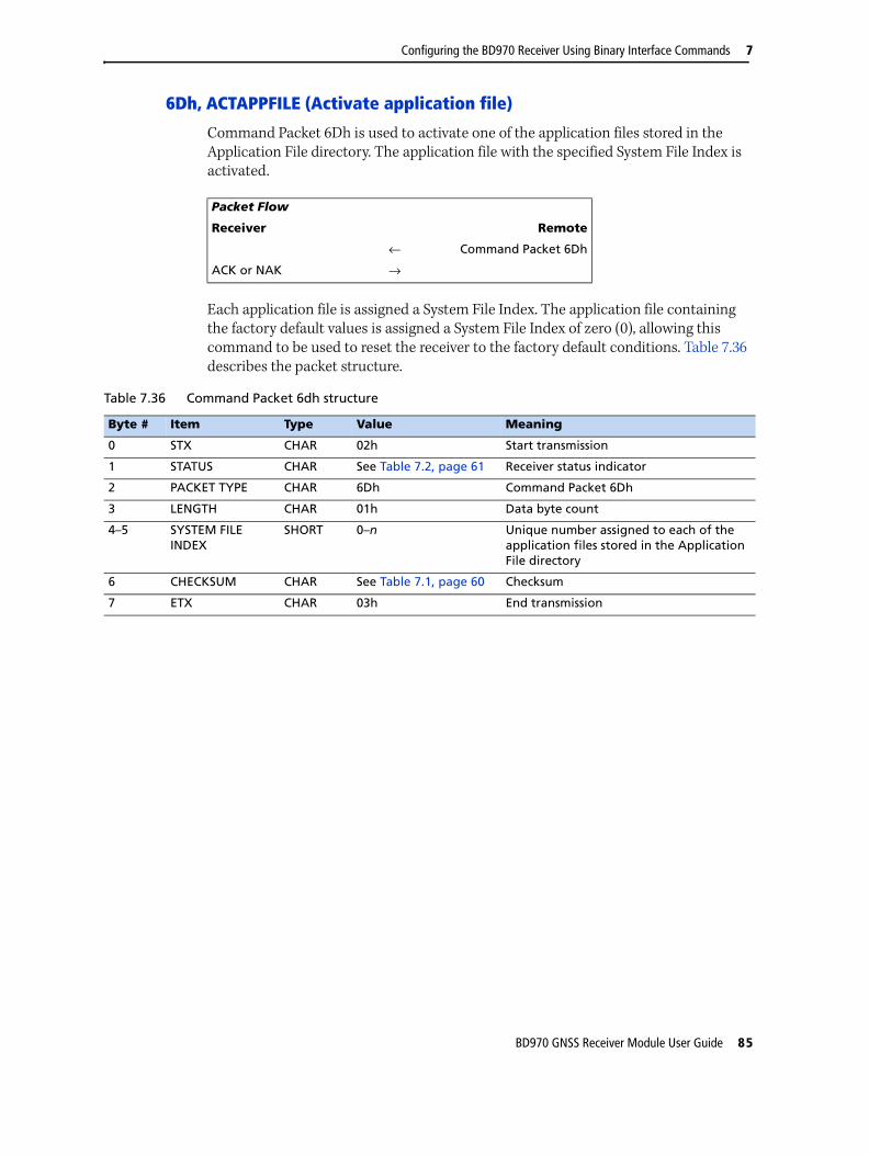
Configuring the BD970 Receiver Using Binary Interface Commands 7
6Dh, ACTAPPFILE (Activate application file)
Command Packet 6Dh is used to activate one of the application files stored in the Application File directory. The application file with the specified System File Index is activated.
Each application file is assigned a System File Index. The application file containing the factory default values is assigned a System File Index of zero (0), allowing this command to be used to reset the receiver to the factory default conditions. Table 7.36 describes the packet structure.
Packet Flow
Receiver Remote
← Command Packet 6Dh
ACK or NAK →
Table 7.36 Command Packet 6dh structure
Byte # Item Type Value Meaning
0 STX CHAR 02h Start transmission
1 STATUS CHAR See Table 7.2, page 61 Receiver status indicator
2 PACKET TYPE CHAR 6Dh Command Packet 6Dh
3 LENGTH CHAR 01h Data byte count
4–5 SYSTEM FILE INDEX
SHORT 0–n Unique number assigned to each of the application files stored in the Application File directory
6 CHECKSUM CHAR See Table 7.1, page 60 Checksum
7 ETX CHAR 03h End transmission
BD970 GNSS Receiver Module User Guide 85

7 Configuring the BD970 Receiver Using Binary Interface Commands
81h, KEYSIM (Key simulator)
Command Packet 81h simulates any front panel key press.
Packet Flow
Receiver Remote
← Command Packet 81h
ACK →
Table 7.37 Command Packet 81h structure
Byte # Item Type Value Meaning
0 STX CHAR 02h Start transmission
1 STATUS CHAR See Table 7.2, page 61 Receiver status code
2 PACKET TYPE CHAR 81h Command Packet 81h
3 LENGTH CHAR 01h Data byte count
4 KEY ID CHAR See Table 7.38, page 86 Key scan code ID
5 CHECKSUM CHAR See Table 7.1, page 60 Checksum values
6 ETX CHAR 03h End transmission
Table 7.38 Key ID codes
Scan Code Receiver Key ASCII Character
7Fh [CLEAR] [Del] <del>
0Dh [ENTER] [Enter] <carriage return>
41h Softkey Choice 1 <A>
42h Softkey Choice 2 <B>
43h Softkey Choice 3 <C>
44h Softkey Choice 4 <D>
1Dh [<] —
1Ch [>] —
30h [0] <0>
31h [1] <1>
32h [2] <2>
33h [3] <3>
34h [4] <4>
35h [5] <5>
36h [6] <6>
37h [7] <7>
38h [8] <8>
39h [9] <9>
4Ch [STATUS] <L>
4Ah [SESSION] <J>
4Bh [SAT{{INFO] <K>
4Fh [LOG{{DATA] <O>
86 BD970 GNSS Receiver Module User Guide

Configuring the BD970 Receiver Using Binary Interface Commands 7
4Dh [CONTROL] <M>
50h [ALPHA] <P>
4Eh [MODIFY] <N>
1Bh [POWER] —
Table 7.38 Key ID codes (continued)
Scan Code Receiver Key ASCII Character
BD970 GNSS Receiver Module User Guide 87

7 Configuring the BD970 Receiver Using Binary Interface Commands
82h, SCRDUMP (Screen dump request)
Command Packet 82h has two forms—a command packet and report packet. Both packets are assigned the same hexadecimal code (82h).
Command Packet 82h requests an ASCII representation of a BD970 simulated display screen. In response, Report Packet 82h sends the data used that is used to display the screen to the remote device in ASCII format.
Table 7.39 shows the command packet structure. For more information, see 82h, SCRDUMP (Screen dump), page 141.
Packet Flow
Receiver Remote
← Command Packet 82h
Report Packet 82h →
Table 7.39 Command packet 82h structure
Byte # Item Type Value Meaning
0 STX CHAR 02h Start transmission
1 STATUS CHAR See Table 7.2, page 61 Receiver status code
2 PACKET TYPE CHAR 82h Command Packet 82h
3 LENGTH CHAR 0h Data bytes count
4 CHECKSUM CHAR See Table 7.1, page 60 Checksum value
5 ETX CHAR 03h End transmission
88 BD970 GNSS Receiver Module User Guide
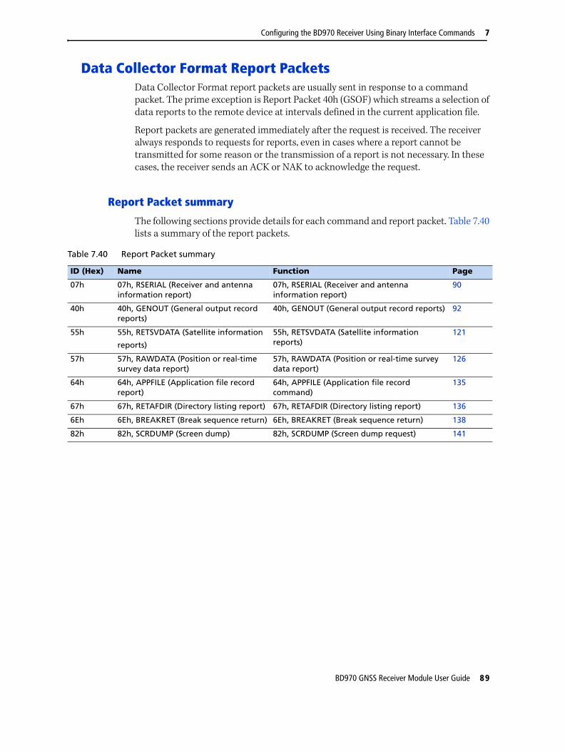
Configuring the BD970 Receiver Using Binary Interface Commands 7
Data Collector Format Report PacketsData Collector Format report packets are usually sent in response to a command packet. The prime exception is Report Packet 40h (GSOF) which streams a selection of data reports to the remote device at intervals defined in the current application file.
Report packets are generated immediately after the request is received. The receiver always responds to requests for reports, even in cases where a report cannot be transmitted for some reason or the transmission of a report is not necessary. In these cases, the receiver sends an ACK or NAK to acknowledge the request.
Report Packet summary
The following sections provide details for each command and report packet. Table 7.40 lists a summary of the report packets.
Table 7.40 Report Packet summary
ID (Hex) Name Function Page
07h 07h, RSERIAL (Receiver and antenna information report)
07h, RSERIAL (Receiver and antenna information report)
90
40h 40h, GENOUT (General output record reports)
40h, GENOUT (General output record reports) 92
55h 55h, RETSVDATA (Satellite information
reports)
55h, RETSVDATA (Satellite information reports)
121
57h 57h, RAWDATA (Position or real-time survey data report)
57h, RAWDATA (Position or real-time survey data report)
126
64h 64h, APPFILE (Application file record report)
64h, APPFILE (Application file record command)
135
67h 67h, RETAFDIR (Directory listing report) 67h, RETAFDIR (Directory listing report) 136
6Eh 6Eh, BREAKRET (Break sequence return) 6Eh, BREAKRET (Break sequence return) 138
82h 82h, SCRDUMP (Screen dump) 82h, SCRDUMP (Screen dump request) 141
BD970 GNSS Receiver Module User Guide 89

7 Configuring the BD970 Receiver Using Binary Interface Commands
07h, RSERIAL (Receiver and antenna information report)
Report Packet 07h is sent in response to the Command Packet 06h. The report returns the receiver and antenna serial number, antenna type, software processor versions, and the number of receiver channels.
Table 7.41 describes the packet structure. For more information, see 06h, GETSERIAL (Receiver and antenna information request), page 65.
Packet Flow
Receiver Remote
← Command Packet 06h
Report Packet 07h →
Table 7.41 Report Packet 07h structure
Byte # Item Type Value Meaning
0 STX CHAR 02h Start transmission.
1 STATUS CHAR See Table 7.2, page 61 Receiver status code.
2 PACKET TYPE CHAR ??h Report Packet 07h.
3 LENGTH CHAR 2Dh Data byte count.
4–11 RECEIVER SERIAL # CHAR ASCII text Receiver serial number.
12–19 RECEIVER TYPE CHARs "BD970" Receiver model designation (padded with three spaces).
20–24 NAV PROCESS VERSION
CHARs ASCII text Version number of NAV Processor software.
25–29 SIG PROCESS VERSION
CHARs ASCII text(00000)
Not applicable.
30–34 BOOT ROM VERSION
CHARs ASCII text(00000)
Not applicable.
35–42 ANTENNA SERIAL # CHARs ASCII text(8 spaces)
Not used.
43–44 ANTENNA TYPE CHAR ASCII text(2 spaces)
Not used.
45–46 # CHANNELS CHAR 12h There are 18 receiver channels.
47–48 # CHANNELS L1 CHAR 09h Nine (9) L1 receiver channels.
49 - 58 LONG SERIAL NUMBER
CHARValue ASCII text (10 spaces) This is the serial number that should be used for newer receivers like the BD970.
59 - 89 LOCAL LONG ANT SERIAL
CHAR ASCII text (31 spaces) Not Applicable
90 - 120 BASE LONG ANT SERIAL
CHAR ASCII text (31 spaces) Not Applicable
121 - 151 BASE NGS ANT DESCRIPTOR
CHAR ASCII text (31 spaces) Not Applicable
152-153 # USABLE CHANNELS
CHAR Maximum usable channels with the current option set.
154-155 # PHYSICAL CHANNELS
CHAR Number of hardware channels.
90 BD970 GNSS Receiver Module User Guide

Configuring the BD970 Receiver Using Binary Interface Commands 7
156 # SIMULTANEOUS CHANNELS
CHAR How many satellites can be tracked at once.
157-161 Reserved N/A N/A N/A
162 CHECKSUM CHAR See Table 7.1, page 60 Checksum value.
163 ETX CHAR 03h End transmission.
Table 7.41 Report Packet 07h structure (continued)
Byte # Item Type Value Meaning
BD970 GNSS Receiver Module User Guide 91

7 Configuring the BD970 Receiver Using Binary Interface Commands
40h, GENOUT (General output record reports)
When scheduled, Report Packet 40h is continuously output at the FREQUENCY specified by the current application file. The GENOUT report contains multiple sub-records as scheduled by the application file (subtype = 10, GSOF).
For information about controlling the record types included in Report Packet 40h, see command packet 64h Appfile.
Where:
• TRANSMISSION NUMBER is a unique number assigned to a chapter of pages indicating that the pages are from the same group.
• PAGE INDEX is the page number of this page in a sequence (chapter) of pages and is zero based.
• MAX PAGE INDEX is the index of the last page in the chapter.
• RECORD LENGTH is the length of data in the record (excluding type and size).
Page Numbering – The Page Index and Max Page Index fields are 0-based, so for example the first transmission of a 2-page set will be 0/1 (PAGE/MAX PAGE) and the 2nd (last) page will be 1/1. The total number of pages is MAX PAGE INDEX + 1.
Packet Flow
Receiver Connected computer
(02h) STX →
(??h) STATUS →
(40h) TYPE →
(??h) LENGTH →
1 (byte) TRANSMISSION NUMBER →
1 (byte) PAGE INDEX →
1 (byte) MAX PAGE INDEX →
Various record types
1 (byte) OUTPUT RECORD TYPE →
1 (byte) RECORD LENGTH →
Various fields dependant on RECORD TYPE.
→
There can be multiple records in one GENOUT packet. There could be multiple GENOUT packets per epoch. Records may be split over two consecutive packets.
(??h) CHECKSUM →
(03h) ETX →
92 BD970 GNSS Receiver Module User Guide

Configuring the BD970 Receiver Using Binary Interface Commands 7
GSOF record types
Table 7.42 GSOF record types
Record number Description Page
1 POSITION TIME 94
2 LAT, LONG, HEIGHT 96
3 ECEF POSITION 97
4 LOCAL DATUM POSITION 98
5 LOCAL ZONE POSITION 99
6 ECEF DELTA 100
7 TANGENT PLANE DELTA 101
8 VELOCITY DATA 102
9 PDOP INFO 103
10 CLOCK INFO 104
11 POSITION VCV INFO 105
12 POSITION SIGMA INFO 106
13 SV BRIEF INFO 107
14 SV DETAILED INFO 108
15 RECEIVER SERIAL NUMBER 110
16 CURRENT TIME 111
26 POSITION TIME UTC 112
27 ATTITUDE INFO*+ 114
33 ALL SV BRIEF INFO 116
34 ALL SV DETAILED INFO 117
35 RECEIVED BASE INFO 119
41 BASE POSITION AND QUALITY INDICATOR 120
BD970 GNSS Receiver Module User Guide 93

7 Configuring the BD970 Receiver Using Binary Interface Commands
GSOF 1: GSOF 1 (01h) POSITION TIME
Where:
• OUTPUT RECORD TYPE = 1.
• RECORD LENGTH is the length of this sub-record.
• GPS TIME is in milliseconds of the GPS week.
• GPS WEEK NUMBER is the week count since January 1980.
• NUMBER OF SVS USED is the number of satellites used to determine the position.
• POSITION FLAGS 1 reports position attributes and is defined as follows:
– bit 0 SET: New Position
– bit 1 SET: Clock fix calculated this position
– bit 2 SET: Horizontal coordinates calculated this position
– bit 3 SET: Height calculated this position
– bit 4 reserved: Always SET (was "Weighted position")
– bit 5 SET: Least squares position
– bit 6 reserved: Always CLEAR (was "Iono-free position")
– bit 7 SET: Position uses Filtered L1 pseudoranges
• POSITION FLAGS 2 reports position attributes and is defined as follows:
– bit 0 SET: Position is a differential solution. RESET: Position is autonomous or WAAS solution.
– bit 1 SET: Differential position is phase including RTK ( float, fixed or location), HP or XP Omnistar (VBS is not derived from phase). RESET: Differential position is code.
Packet Flow
Receiver Connected computer
1 (byte) OUTPUT RECORD TYPE = 1 →
1 (byte) RECORD LENGTH →
4 (long) GPS TIME (ms) →
2 (int) GPS WEEK NUMBER →
1 (byte) NUMBER OF SVS USED →
1 (byte) POSITION FLAGS 1 →
1 (byte) POSITION FLAGS 2 →
1 (byte) INITIALIZATION NUMBER →
94 BD970 GNSS Receiver Module User Guide

Configuring the BD970 Receiver Using Binary Interface Commands 7
– bit 2 SET: Differential position is fixed integer phase position (RTK-fixed). Uncorrected position is WAAS (if bit 0 is 0). RESET: Differential position is RTK-float, RTK-location or code phase (DGPS), Uncorrected position is Autonomous (if bit 0 is 0).
– bit 3 SET: OmniSTAR differential solution (including HP, XP, and VBS.) RESET: Not OmniSTAR solution.
– bit 4 SET: Position determined with STATIC as a constraint.
– bit 5 SET: Position is Network RTK solution.
– bit 6 SET: RTK-Location.
– bit 7 SET: Beacon DGPS.
• INITIALIZATION NUMBER is a rollover counter to indicate when re-initializations have taken place.
BD970 GNSS Receiver Module User Guide 95

7 Configuring the BD970 Receiver Using Binary Interface Commands
GSOF 2: GSOF 2 (02h) LAT, LONG, HEIGHT
Where:
• OUTPUT RECORD TYPE = 2.
• RECORD LENGTH is the length of this sub-record.
• LATITUDE is the WGS-84 latitude in radians.
• LONGITUDE is the WGS-84 longitude in radians.
• HEIGHT is the WGS-84 height in meters.
Packet Flow
Receiver Connected computer
1 (byte) OUTPUT RECORD TYPE = 2 →
1 (byte) RECORD LENGTH →
8 (double) LATITUDE →
8 (double) LONGITUDE →
8 (double) HEIGHT →
96 BD970 GNSS Receiver Module User Guide

Configuring the BD970 Receiver Using Binary Interface Commands 7
GSOF 3: GSOF 3 (03h) ECEF POSITION
Where:
• OUTPUT RECORD TYPE = 3.
• RECORD LENGTH is the length of this sub-record.
• X is the earth-centered earth-fixed X axis WGS-84 coordinate of the position in meters.
• Y is the earth-centered earth-fixed Y axis WGS-84 coordinate of the position in meters.
• Z is the earth-centered earth-fixed Z axis WGS-84 coordinate of the position in meters.
Packet Flow
Receiver Connected computer
1 (byte) OUTPUT RECORD TYPE = 3 →
1 (byte) RECORD LENGTH →
8 (double) X →
8 (double) Y →
8 (double) Z →
BD970 GNSS Receiver Module User Guide 97

7 Configuring the BD970 Receiver Using Binary Interface Commands
GSOF 4: GSOF 4 (04h) LOCAL DATUM POSITION.
Back to: 40h GENOUT
Where:
• OUTPUT RECORD TYPE = 4.
• RECORD LENGTH is the length of this sub-record.
• LOCAL DATUM IDENTIFIER is an ASCII string that identifies the coordinate datum.
• LOCAL DATUM LATITUDE is the latitude in the local datum (radians).
• LOCAL DATUM LONGITUDE is the longitude in the local datum (radians).
• LOCAL DATUM HEIGHT is the height in the local datum (meters).
Packet Flow
Receiver Connected computer
1 (byte) OUTPUT RECORD TYPE = 4 →
1 (byte) RECORD LENGTH →
8 (char) LOCAL DATUM ID →
8 (double) LOCAL DATUM ECEF LATITUDE
→
8 (double) LOCAL DATUM LONGITUDE
→
8 (double) LOCAL DATUM HEIGHT →
1 (byte) OUTPUT RECORD TYPE = 4 →
98 BD970 GNSS Receiver Module User Guide
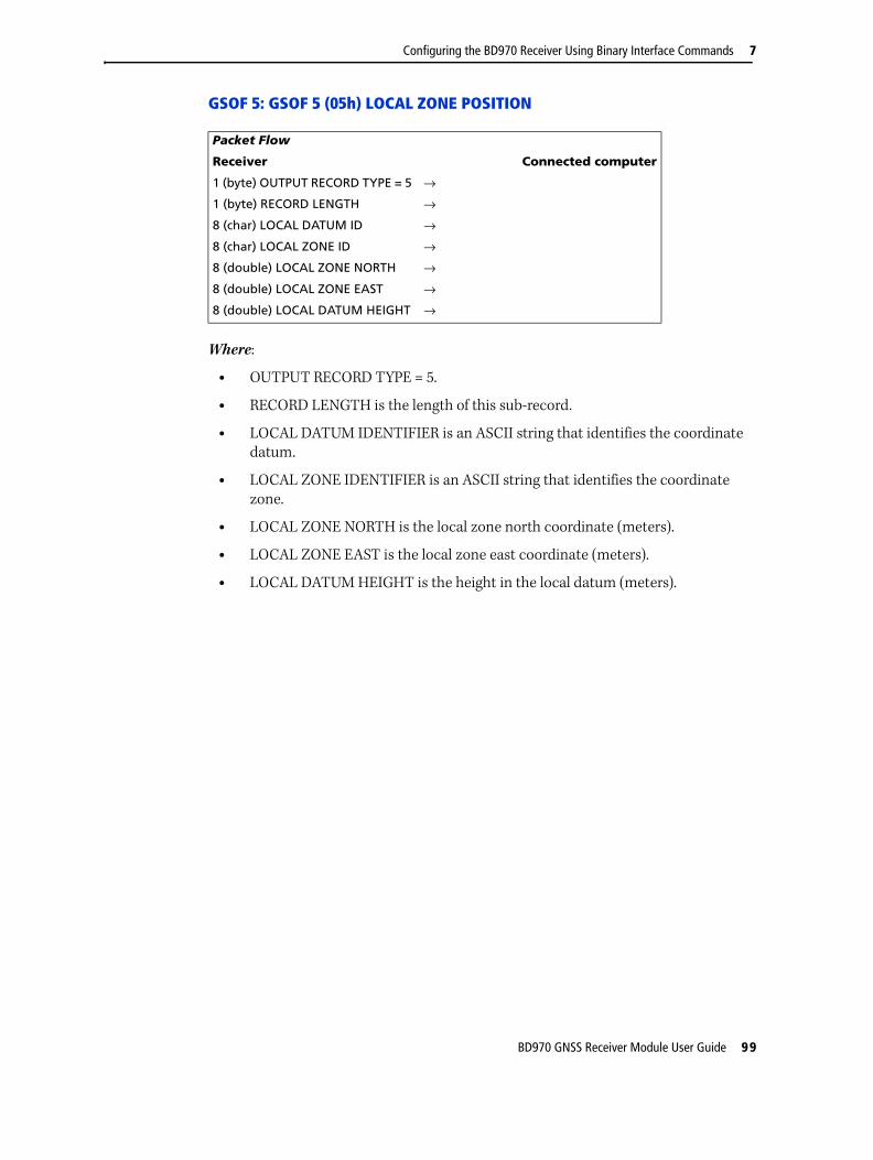
Configuring the BD970 Receiver Using Binary Interface Commands 7
GSOF 5: GSOF 5 (05h) LOCAL ZONE POSITION
Where:
• OUTPUT RECORD TYPE = 5.
• RECORD LENGTH is the length of this sub-record.
• LOCAL DATUM IDENTIFIER is an ASCII string that identifies the coordinate datum.
• LOCAL ZONE IDENTIFIER is an ASCII string that identifies the coordinate zone.
• LOCAL ZONE NORTH is the local zone north coordinate (meters).
• LOCAL ZONE EAST is the local zone east coordinate (meters).
• LOCAL DATUM HEIGHT is the height in the local datum (meters).
Packet Flow
Receiver Connected computer
1 (byte) OUTPUT RECORD TYPE = 5 →
1 (byte) RECORD LENGTH →
8 (char) LOCAL DATUM ID →
8 (char) LOCAL ZONE ID →
8 (double) LOCAL ZONE NORTH →
8 (double) LOCAL ZONE EAST →
8 (double) LOCAL DATUM HEIGHT →
BD970 GNSS Receiver Module User Guide 99

7 Configuring the BD970 Receiver Using Binary Interface Commands
GSOF 6: GSOF 6 (06h) ECEF DELTA
Where:
• OUTPUT RECORD TYPE = 6.
• RECORD LENGTH is the length of this sub-record.
• DELTA X is the ECEF X axis delta between the rover and base positions (rover - base) in meters.
• DELTA Y is the ECEF Y axis delta between the rover and base positions (rover - base) in meters.
• DELTA Z is the ECEF Z axis delta between the rover and base positions (rover - base) in meters.
Packet Flow
Receiver Connected computer
1 (byte) OUTPUT RECORD TYPE = 6 →
1 (byte) RECORD LENGTH →
8 (double) DELTA X →
8 (double) DELTA Y →
8 (double) DELTA Z →
100 BD970 GNSS Receiver Module User Guide
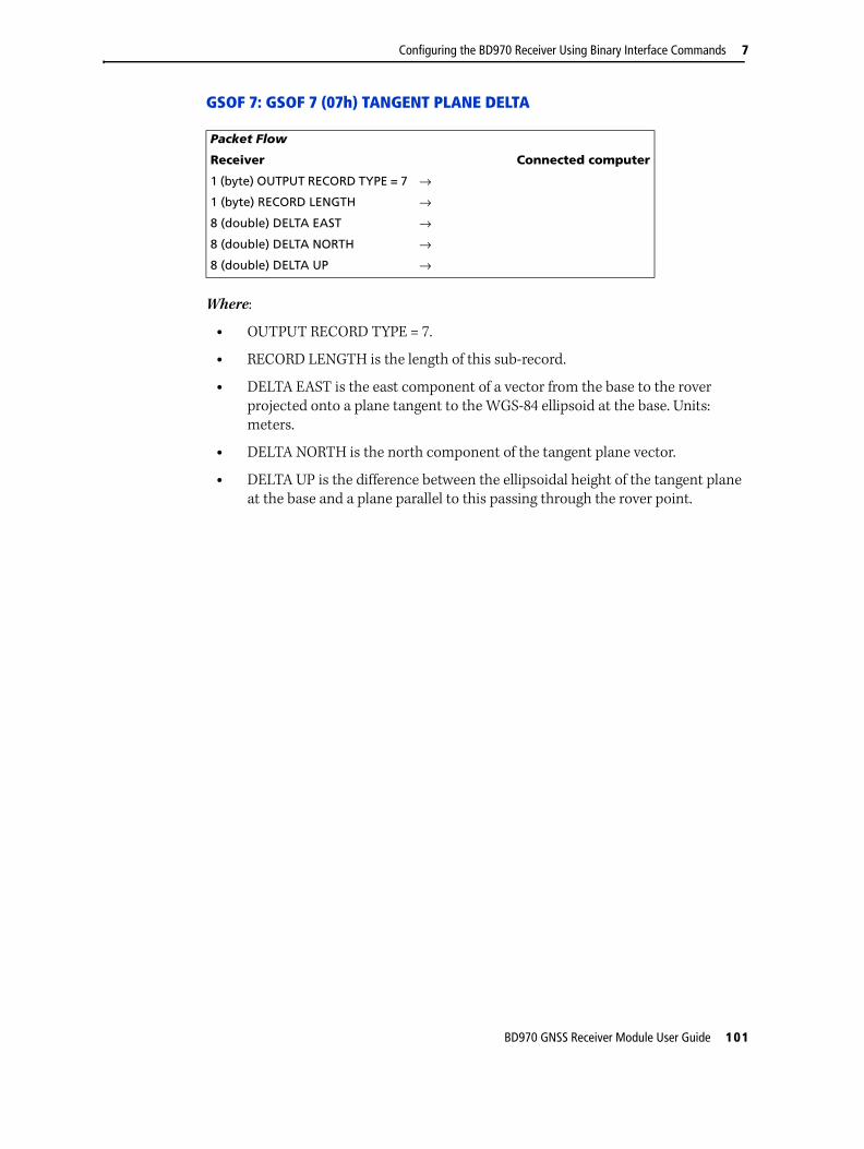
Configuring the BD970 Receiver Using Binary Interface Commands 7
GSOF 7: GSOF 7 (07h) TANGENT PLANE DELTA
Where:
• OUTPUT RECORD TYPE = 7.
• RECORD LENGTH is the length of this sub-record.
• DELTA EAST is the east component of a vector from the base to the rover projected onto a plane tangent to the WGS-84 ellipsoid at the base. Units: meters.
• DELTA NORTH is the north component of the tangent plane vector.
• DELTA UP is the difference between the ellipsoidal height of the tangent plane at the base and a plane parallel to this passing through the rover point.
Packet Flow
Receiver Connected computer
1 (byte) OUTPUT RECORD TYPE = 7 →
1 (byte) RECORD LENGTH →
8 (double) DELTA EAST →
8 (double) DELTA NORTH →
8 (double) DELTA UP →
BD970 GNSS Receiver Module User Guide 101

7 Configuring the BD970 Receiver Using Binary Interface Commands
GSOF 8: GSOF 8 (08h) VELOCITY DATA
Where:
• OUTPUT RECORD TYPE = 8.
• RECORD LENGTH is the length of this sub-record.
• VELOCITY FLAGS indicate attributes of the velocity information. Defined values are:
– bit 0 SET: Velocity data valid. RESET: Velocity data not valid
– bit 1 SET: Velocity computed from consecutive measurements. RESET: Velocity computed from Doppler
– bits 2-7: RESERVED
• VELOCITY is the horizontal velocity in meters per second.
• HEADING is the WGS-84 referenced true north heading in radians.
• VERTICAL VELOCITY is the velocity in the vertical direction in meters per second.
Packet Flow
Receiver Connected computer
1 (byte) OUTPUT RECORD TYPE = 8 →
1 (byte) RECORD LENGTH →
1 (byte) VELOCITY FLAGS →
4 (float) VELOCITY →
4 (float) HEADING →
4 (float) VERTICAL VELOCITY →
102 BD970 GNSS Receiver Module User Guide
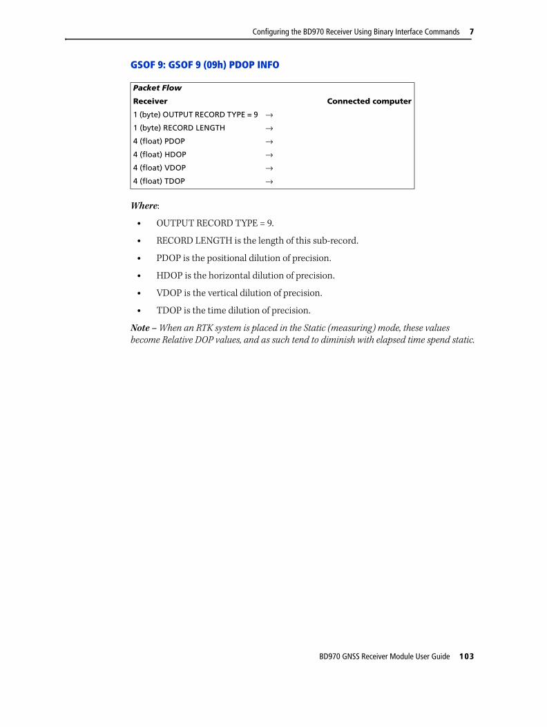
Configuring the BD970 Receiver Using Binary Interface Commands 7
GSOF 9: GSOF 9 (09h) PDOP INFO
Where:
• OUTPUT RECORD TYPE = 9.
• RECORD LENGTH is the length of this sub-record.
• PDOP is the positional dilution of precision.
• HDOP is the horizontal dilution of precision.
• VDOP is the vertical dilution of precision.
• TDOP is the time dilution of precision.
Note – When an RTK system is placed in the Static (measuring) mode, these values become Relative DOP values, and as such tend to diminish with elapsed time spend static.
Packet Flow
Receiver Connected computer
1 (byte) OUTPUT RECORD TYPE = 9 →
1 (byte) RECORD LENGTH →
4 (float) PDOP →
4 (float) HDOP →
4 (float) VDOP →
4 (float) TDOP →
BD970 GNSS Receiver Module User Guide 103

7 Configuring the BD970 Receiver Using Binary Interface Commands
GSOF 10: GSOF 10 (0Ah) CLOCK INFO
Where:
• OUTPUT RECORD TYPE = 10.
• RECORD LENGTH is the length of this sub-record.
• CLOCK FLAGS indicates information relation of the clock fix process. Defined values are:
– bit 0 SET: Clock offset is valid
– bit 1 SET: Frequency offset is valid
– bit 2 SET: Receiver is in anywhere fix mode
– bit 3-7: RESERVED
• CLOCK OFFSET is the current clock offset in milliseconds.
• FREQUENCY OFFSET is the offset of the local oscillator from the nominal GPS L1 frequency in parts per million.
Packet Flow
Receiver Connected computer
1 (byte) OUTPUT RECORD TYPE = 10
→
1 (byte) RECORD LENGTH →
1 (byte) CLOCK FLAGS →
8 (double) CLOCK OFFSET →
8 (double) FREQUENCY OFFSET →
104 BD970 GNSS Receiver Module User Guide

Configuring the BD970 Receiver Using Binary Interface Commands 7
GSOF 11: GSOF 11 (0Bh) POSITION VCV INFO
Where:
• OUTPUT RECORD TYPE = 11.
• RECORD LENGTH is the length of this sub-record.
• RANGE RESIDUAL RMS is the square root of (the sum of the squares of the range residuals divided by the number of degrees of freedom in the solution).
• VCVxx .. VCVzz is the variance-covariance matrix. This contains the positional components of the inverted normal matrix of the position solution in a ECEF WGS-84 reference.
• UNIT VARIANCE is the unit variance of the position solution.
• NUMBER OF EPOCHS indicates the number of measurements used to compute the position. It may be greater than 1 for positions subjected to a STATIC constraint.
Packet Flow
Receiver Connected computer
1 (byte) OUTPUT RECORD TYPE = 11
→
1 (byte) RECORD LENGTH →
4 (float) POSITION RMS →
4 (float) VCV xx →
4 (float) VCV xy →
4 (float) VCV xz →
4 (float) VCV yy →
4 (float) VCV yz →
4 (float) VCV zz →
4 (float) UNIT VARIANCE →
2 (short) NUMBER OF EPOCHS →
BD970 GNSS Receiver Module User Guide 105

7 Configuring the BD970 Receiver Using Binary Interface Commands
GSOF 12: GSOF 12 (0Ch) POSITION SIGMA INFO
Where:
• OUTPUT RECORD TYPE = 12.
• RECORD LENGTH is the length of this sub-record.
• RANGE RESIDUAL RMS is the square root of (the sum of the squares of the range residuals divided by the number of degrees of freedom in the solution).
• SIGMA EAST, NORTH, UP are in meters.
• COVARIANCE EAST-NORTH is dimensionless.
• SEMI-MAJOR/MINOR AXES of the error ellipse is in meters.
• ORIENTATION of the semi-major axis is in degrees from clockwise from True North.
• UNIT VARIANCE is valid only for over determined solutions. It should tend towards 1.0. A value less than 1.0 indicates that the apriori variances were too pessimistic.
• NUMBER OF EPOCHS indicates the number of measurements used to compute the position. It may be greater than 1 for positions subjected to a STATIC constraint.
Packet Flow
Receiver Connected computer
1 (byte) OUTPUT RECORD TYPE = 12
→
1 (byte) RECORD LENGTH →
4 (float) POSITION RMS →
4 (float) SIGMA EAST →
4 (float) SIGMA NORTH →
4 (float) COVAR. EAST-NORTH →
4 (float) SIGMA UP →
4 (float) SEMI MAJOR AXIS →
4 (float) SEMI-MINOR AXIS →
4 (float) ORIENTATION →
4 (float) UNIT VARIANCE →
2 (short) NUMBER EPOCHS →
106 BD970 GNSS Receiver Module User Guide

Configuring the BD970 Receiver Using Binary Interface Commands 7
GSOF 13: GSOF 13 (0Dh) SV BRIEF INFO
Where:
• OUTPUT RECORD TYPE = 13.
• RECORD LENGTH is the length of this sub-record.
• NUMBER OF SVS is the number of tracked satellites reported in this record.
• PRN is the PRN number of the satellite which the following flags refer to.
• SV FLAGS1 indicate conditions relating to satellites. Defined values are:
– bit 0 SET: Above horizon
– bit 1 SET: Currently assigned to a channel (trying to track)
– bit 2 SET: Currently tracked on L1 frequency
– bit 3 SET: Currently tracked on L2 frequency
– bit 4 SET: Reported at Base on L1 frequency
– bit 5 SET: Reported at Base on L2 frequency
– bit 6 SET: Used in Position
– bit 7 SET: Used in current RTK process (search, propagate, fix solution)
• SV FLAGS2 indicate conditions relating to satellites. Defined values are:
– bit 0 SET: Tracking P Code on L1
– bit 1 SET: Tracking P Code on L2
– bit 2 SET: Tracking CS on L2
– bits 3-7: RESERVED
Packet Flow
Receiver Connected computer
1 (byte) OUTPUT RECORD TYPE = 13
→
1 (byte) RECORD LENGTH →
1 (byte) NUMBER OF SVS →
repeated for number of svs
1 (byte) PRN →
1 (byte) SV FLAGS1 →
1 (byte) SV FLAGS2 →
BD970 GNSS Receiver Module User Guide 107

7 Configuring the BD970 Receiver Using Binary Interface Commands
GSOF 14: GSOF 14 (0Eh) SV DETAILED INFO
Where:
• OUTPUT RECORD TYPE = 14.
• RECORD LENGTH is the length of this sub-record.
• NUMBER OF SVS is the number of tracked satellites reported in this record.
• PRN is the PRN number of the satellite which the following information refers to.
• SV FLAGS1 indicate conditions relating to satellites. Defined values are:
– bit 0 SET: Above horizon
– bit 1 SET: Currently assigned to a channel (trying to track)
– bit 2 SET: Currently tracked on L1 frequency
– bit 3 SET: Currently tracked on L2 frequency
– bit 4 SET: Reported at Base on L1 frequency
– bit 5 SET: Reported at Base on L2 frequency
– bit 6 SET: Used in Position
– bit 7 SET: Used in current RTK process (search, propagate, fix solution)
• SV FLAGS2 indicate conditions relating to satellites. Defined values are:
– bit 0 SET: Tracking P Code on L1
– bit 1 SET: Tracking P Code on L2
– bit 2 SET: Tracking CS on L2
– bits 3-7: RESERVED
• ELEVATION is the angle of the satellite above the horizon in degrees.
Packet Flow
Receiver Connected computer
1 (byte) OUTPUT RECORD TYPE = 14
→
1 (byte) RECORD LENGTH →
1 (byte) NUMBER OF SVS →
repeated for number of svs
1 (byte) PRN →
1 (byte) SV FLAGS1 →
1 (byte) SV FLAGS2 →
1 (signed byte) ELEVATION →
2 (short) AZIMUTH →
1 (byte) SNR L1*4 →
1 (byte) SNR L2*4 →
108 BD970 GNSS Receiver Module User Guide
Configuring the BD970 Receiver Using Binary Interface Commands 7
• AZIMUTH is the azimuth of the satellite form true north in degrees.
• SNR L1 is the signal-to-noise ratio of the L1 signal (multiplied by 4). 0 for SVs not tracked on this frequency.
• SNR L2 is the signal-to-noise ratio of the L2 signal (multiplied by 4). 0 for SVs not tracked on this frequency.
BD970 GNSS Receiver Module User Guide 109
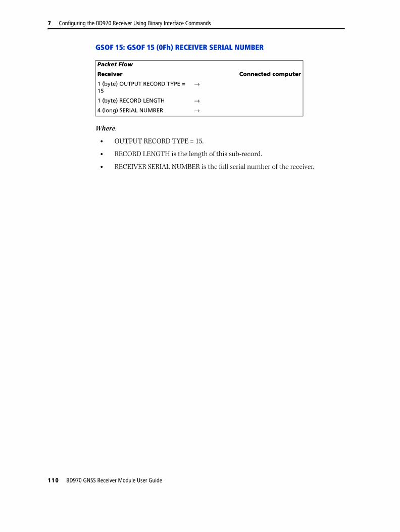
7 Configuring the BD970 Receiver Using Binary Interface Commands
GSOF 15: GSOF 15 (0Fh) RECEIVER SERIAL NUMBER
Where:
• OUTPUT RECORD TYPE = 15.
• RECORD LENGTH is the length of this sub-record.
• RECEIVER SERIAL NUMBER is the full serial number of the receiver.
Packet Flow
Receiver Connected computer
1 (byte) OUTPUT RECORD TYPE = 15
→
1 (byte) RECORD LENGTH →
4 (long) SERIAL NUMBER →
110 BD970 GNSS Receiver Module User Guide

Configuring the BD970 Receiver Using Binary Interface Commands 7
GSOF 16: GSOF 16 (10h) CURRENT TIME
Where:
• OUTPUT RECORD TYPE = 16.
• RECORD LENGTH is the length of this sub-record.
• GPS MILLISECONDS OF WEEK is the time that the message was sent from the receiver.
• GPS WEEK NUMBER is the full week number since start of GPS time.
• UTC OFFSET is the current GPS to UTC time offset in integer seconds.
• FLAGS indicate the validity of the time and UTC offset parameters. Defined values are:
– bit 0 SET: Time information (week and milliseconds of week) valid
– bit 1 SET: UTC Offset is valid
Packet Flow
Receiver Connected computer
1 (byte) OUTPUT RECORD TYPE = 16
→
1 (byte) RECORD LENGTH →
4 (long) GPS MILLISEC OF WEEK →
2 (short) GPS WEEK NUMBER
2 (short) UTC OFFSET
1 (byte) FLAGS
BD970 GNSS Receiver Module User Guide 111

7 Configuring the BD970 Receiver Using Binary Interface Commands
GSOF 26: GSOF 26 (1Ah) POSITION TIME UTC
Where:
• OUTPUT RECORD TYPE = 26.
• RECORD LENGTH is the length of this sub-record.
• MILLISECONDS OF WEEK is the GPS time since the start of the GPS week.
• GPS WEEK NUMBER is the week count since January 1980.
• NUMBER OF SVS USED is the number of satellites used to determine the position.
• POSITION FLAGS 1 reports position attributes and is defined as follows:
– bit 0 SET: New Position
– bit 1 SET: Clock fix calculated this position
– bit 2 SET: Horizontal coordinates calculated this position
– bit 3 SET: Height calculated this position
– bit 4 reserved: Always SET (was "Weighted position")
– bit 5 SET: Least squares position
– bit 6 reserved: Always CLEAR (was "Iono-free position")
– bit 7 SET: Position uses Filtered L1 pseudoranges
• POSITION FLAGS 2 reports position attributes and is defined as follows:
– bit 0 SET: Position is a differential solution. RESET: Position is autonomous or WAAS solution.
– bit 1 SET: Differential position is phase (RTK, or HP Omnistar). RESET: Differential position is code.
– bit 2 SET: Differential position is fixed integer phase position (RTK). Uncorrected position is WAAS (if bit 0 is 0). RESET: Differential position is RTK-float or code phase (DGPS). Uncorrected position is Autonomous (if bit 0 is 0).
Packet Flow
Receiver Connected computer
1 (byte) OUTPUT RECORD TYPE = 26
→
1 (byte) RECORD LENGTH →
4 (long) MILLISECONDS OF WEEK →
2 (short) GPS WEEK NUMBER →
1 (byte) NUMBER OF SVS USED →
1 (byte) POSITION FLAGS 1 →
1 (byte) POSITION FLAGS 2 →
1 (byte) INITIALIZATION NUMBER →
112 BD970 GNSS Receiver Module User Guide

Configuring the BD970 Receiver Using Binary Interface Commands 7
– bit 3 SET: HP / Omnistar differential solution. RESET: HP / Omnistar not active.
– bit 4 SET: Position determined with STATIC as a constraint
– bit 5 SET: Position is Network RTK solution
– bits 6-7: RESERVED
• INITIALIZATION NUMBER is a rollover counter to indicate when re-initializations have taken place.
BD970 GNSS Receiver Module User Guide 113

7 Configuring the BD970 Receiver Using Binary Interface Commands
GSOF 27: GSOF 27 (1Bh) ATTITUDE INFO
Where:
• OUTPUT RECORD TYPE = 27.
• RECORD LENGTH is the length of this sub-record.
• GPS TIME is time of position in milliseconds of GPS week.
• FLAGS indicate the following:
– bit 0: Calibrated
– bit 1: Pitch Valid
– bit 2: Yaw Valid
– bit 3: Roll Valid
– bit 4: Scalar Valid
– bit 5 - Bit 7: Reserved
– bit 5: Diagnostic Valid
Packet Flow
Receiver Connected computer
1 (byte) OUTPUT RECORD TYPE = 27
→
1 (byte) RECORD LENGTH →
4 (unsigned long) GPS TIME →
1 (byte) FLAGS →
1 (byte) NUMBER OF SVS →
1 (byte) CALCULATION MODE →
1 (byte) RESERVED →
8 (double) PITCH →
8 (double) YAW →
8 (double) ROLL →
8 (double) MASTER-SLAVE RANGE →
2 (word) PDOP
Record length = 42, up to and including PDOP (does not include type and length bytes)
→
4 (float) PITCH VARIANCE →
4 (float) YAW VARIANCE →
4 (float) ROLL VARIANCE →
4 (float) MASTER-SLAVE RANGE VARIANCE
Record length = 70 up to and including Master Slave Range Variance
→
114 BD970 GNSS Receiver Module User Guide
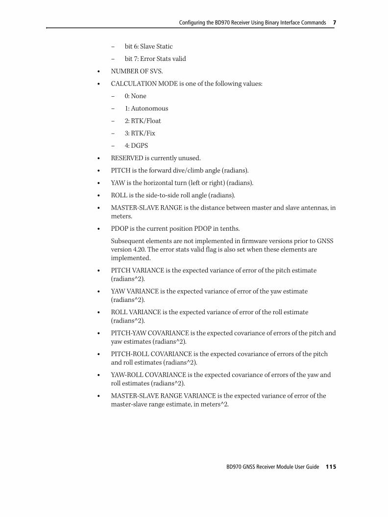
Configuring the BD970 Receiver Using Binary Interface Commands 7
– bit 6: Slave Static
– bit 7: Error Stats valid
• NUMBER OF SVS.
• CALCULATION MODE is one of the following values:
– 0: None
– 1: Autonomous
– 2: RTK/Float
– 3: RTK/Fix
– 4: DGPS
• RESERVED is currently unused.
• PITCH is the forward dive/climb angle (radians).
• YAW is the horizontal turn (left or right) (radians).
• ROLL is the side-to-side roll angle (radians).
• MASTER-SLAVE RANGE is the distance between master and slave antennas, in meters.
• PDOP is the current position PDOP in tenths.
Subsequent elements are not implemented in firmware versions prior to GNSS version 4.20. The error stats valid flag is also set when these elements are implemented.
• PITCH VARIANCE is the expected variance of error of the pitch estimate (radians^2).
• YAW VARIANCE is the expected variance of error of the yaw estimate (radians^2).
• ROLL VARIANCE is the expected variance of error of the roll estimate (radians^2).
• PITCH-YAW COVARIANCE is the expected covariance of errors of the pitch and yaw estimates (radians^2).
• PITCH-ROLL COVARIANCE is the expected covariance of errors of the pitch and roll estimates (radians^2).
• YAW-ROLL COVARIANCE is the expected covariance of errors of the yaw and roll estimates (radians^2).
• MASTER-SLAVE RANGE VARIANCE is the expected variance of error of the master-slave range estimate, in meters^2.
BD970 GNSS Receiver Module User Guide 115

7 Configuring the BD970 Receiver Using Binary Interface Commands
GSOF 33: GSOF 33 (21h) ALL SV BRIEF INFO
Where:
• OUTPUT RECORD TYPE = 33.
• RECORD LENGTH is the length of this sub-record.
• NUMBER OF SVS is the number of tracked satellites reported in this record.
• PRN is the PRN number of the satellite which the following flags refer to. This will be the ACTUAL PRN number given by the SV (not ranged due to SV system) due to the next field:
• SV System is the system that the SV belongs to.
– 0 = GPS
– 1 = SBAS
– 2 = GLONASS
– 3 = GALILEO
– 4 - 255: RESERVED
• SV FLAGS1 indicate conditions relating to satellites.
– bit 0 set: Above horizon
– bit 1 set: Currently assigned to a channel (trying to track)
– bit 2 set: Currently tracked on L1/G1 frequency
– bit 3-7: RESERVED
• SV FLAGS2 indicate conditions relating to satellites.
– bits 0-7: RESERVED
Packet Flow
Receiver Connected computer
1 (byte) OUTPUT RECORD TYPE = 33
→
1 (byte) RECORD LENGTH →
1 (byte) NUMBER OF SVs →
Repeated for number of SVs
1 (byte) PRN →
1 (byte) SV System →
1 (byte) SV FLAGS1 →
1 (byte) SV FLAGS2 →
116 BD970 GNSS Receiver Module User Guide

Configuring the BD970 Receiver Using Binary Interface Commands 7
GSOF 34: GSOF 34 (22h) ALL SV DETAILED INFO
Where:
• OUTPUT RECORD TYPE = 34.
• RECORD LENGTH is the length of this sub-record.
• NUMBER OF SVS is the number of tracked satellites reported in this record.
• PRN is the PRN number of the satellite which the following flags refer to. This will be the ACTUAL PRN number given by the SV (not ranged due to SV system) due to the next field.
• SV SYSTEM is the system that the SV belongs to.
– 0: GPS
– 1: SBAS
– 2: GLONASS
– 3 - 9: RESERVED
– 10: OMNISTAR
– 11 - 255: RESERVED
• SV FLAGS1 is a bitmap field having the following values:
– bit 0 Set: Above horizon
– bit 1 Set: Currently assigned to a channel (trying to track)
– bit 2 Set: Currently tracked on L1/G1 frequency
– bit 3 Set: Currently tracked on L2/G2 frequency
Packet Flow
Receiver Connected computer
1 (byte) OUTPUT RECORD TYPE = 34
→
1 (byte) RECORD LENGTH →
1 (byte) NUMBER OF SVS →
Repeated for number of SVs
1 (byte) PRN →
1 (byte) SV SYSTEM →
1 (byte) SV FLAGS1 →
1 (byte) SV FLAGS2 →
1 (signed byte) ELEVATION →
2 (short) AZIMUTH →
1 (byte) SNR L1*4 →
1 (byte) SNR L2*4 →
1 (byte) SNR L5*4 OR G1P SNR OR Galileo SNR
→
BD970 GNSS Receiver Module User Guide 117

7 Configuring the BD970 Receiver Using Binary Interface Commands
– bit 4 Set: Reported at base on L1/G1 frequency
– bit 5 Set: Reported at base on L2/G2 frequency
– bit 6 Set: Used in current position
– bit 7 Set: Used in the current RTK solution.
• SV FLAGS2 is a bitmap variable having the following values:
– bit 0 Set: Tracking P-Code on L1/G1
– bit 1 Set: Tracking P-Code on L2
• IF GPS SV:
– bit 2 Set: Tracking CS on L2
– bit 3 Set: Tracking L5 Signal
– Bits 4-7 are reserved
• If GLONASS SV:
– bit 2 Set: Glonass SV is “M” SV
– bit 3 Set: Glonass SV is “K” SV
– Bits 4-7 are reserved
• ELSE
– Bits 2-7 are reserved
• ELEVATION is the angle of the satellite above the horizon in degrees.
• AZIMUTH is the azimuth of the satellite form true north in degrees.
• SNR L1 is the signal-to-noise ratio of the L1 signal (multiplied by 4). 0 for SVs not tracked on this frequency.
• SNR L2 is the signal-to-noise ratio of the L2 signal (multiplied by 4). 0 for SVs not tracked on this frequency.
• IF GPS SNR L5 is the signal-to-noise ratio of the L5 signal (multiplied by 4). 0 for SVs not tracked on this frequency.
• IF GLONASS G1P SNR is the signal-to-noise ratio of the G1P signal (multiplied by 4). 0 for SVs not tracked on this frequency.
• IF Galileo, E1 SNR or E5A SNR or E5B SNR or E5AltBOC SNR
• ELSE This last byte is RESERVED.
118 BD970 GNSS Receiver Module User Guide

Configuring the BD970 Receiver Using Binary Interface Commands 7
GSOF 35: GSOF 35 (23h) RECEIVED BASE INFO
Where:
• OUTPUT RECORD TYPE = 35.
• RECORD LENGTH is the length of this sub-record.
• FLAGS specifies a few attributes about the BASE (and ONLY the base, since there are status flags about RTK in other messages). Defined values:
– Bits 0 - 2 specify a “version number” for this message.
– Bit 3 if SET specifies that the base info given is valid.
– Bits 4 - 7 are currently RESERVED.
• BASE NAME is the short base name received from the base. In the case of the base being RTCM (with no base name), the field is set to all 0s.
• BASE ID is the ID# of the base being used. This field is big-endian, so the first byte will always be set to 0 if the base is a CMR base.
• BASE LATITUDE is the WGS-84 latitude of the base in radians.
• BASE LONGITUDE is the WGS-84 longitude of the base in radians.
• BASE HEIGHT is the WGS-84 height of the base in meters.
Packet Flow
Receiver Connected computer
1 (byte) OUTPUT RECORD TYPE = 35
→
1 (byte) RECORD LENGTH →
1 (Byte) FLAGS and VERSION OF MESSAGE
→
8 (chars) BASE NAME →
2 (bytes) BASE ID →
8 (double) BASE LATITUDE →
8 (double) BASE LONGITUDE →
8 (double) BASE HEIGHT →
BD970 GNSS Receiver Module User Guide 119

7 Configuring the BD970 Receiver Using Binary Interface Commands
GSOF 41: GSOF 41 (29h) BASE POSITION AND QUALITY INDICATOR
Where:
• OUTPUT RECORD TYPE = 41.
• RECORD LENGTH is the length of this sub-record.
• GPS TIME is in milliseconds of the GPS week.
• GPS WEEK NUMBER is the week count since January 1980.
• LATITUDE is the base WGS-84 latitude in radians.
• LONGITUDE is the base WGS-84 longitude in radians.
• HEIGHT is the base WGS-84 height in meters.
• QUALITY INDICATOR shows the quality of the base position:
– 0 - Fix not available or invalid
– 1 - Autonomous
– 2 - Differential, SBAS or OmniSTAR VBS
– 4 - RTK Fixed
– 5 - OmniSTAR XP, OmniSTAR HP, RTK Float, or RTK Location
Packet Flow
Receiver Connected computer
1 (byte) OUTPUT RECORD TYPE = 41
→
1 (byte) RECORD LENGTH →
4 (long) GPS TIME (ms) →
2 (int) GPS WEEK NUMBER →
8 (double) LATITUDE →
8 (double) LONGITUDE →
8 (double) HEIGHT →
1 (byte) QUALITY INDICATOR →
120 BD970 GNSS Receiver Module User Guide

Configuring the BD970 Receiver Using Binary Interface Commands 7
55h, RETSVDATA (Satellite information reports)
Report Packet 55h is sent in response to Command Packet 54h. The report includes either the ephemeris or almanac information for a specific satellite, or ION/UTC data, the Enabled/Disabled state and Heed/Ignore Health state of all satellites, or the condition of satellite status flags for one satellite or all satellites.
Only the satellite information, requested by Command Packet 54h, is sent in the report packet. As a result, several forms of the Report Packet 55h can be requested.
Table 7.43 through Table 7.47 describe the structure of the report packets.
Returns a NAK if the GETSVDATA request meets one of the following criteria:
• SV PRN is out of range 1–32 (except for SV flags)
• Data Switch is out of range
• Data is not available for the requested SV
SV FLAGS report
The SV FLAGS report is sent when Command Packet 54h is used to request the status of the SV Flags for one satellite or all satellites. The Command Packet 54h DATA
SWITCH byte (byte 4) is set to zero (0) when requesting the report. Table 7.43 describes the packet structure.
Packet Flow
Receiver Remote
← Command Packet 54h
Report Packet 55h →
Table 7.43 Report Packet 55h SV flags report structure
Byte # Item Type Value Meaning
0 STX CHAR 02h Start transmission.
1 STATUS CHAR See Table 7.2, page 61 Receiver status.
2 PACKET TYPE CHAR 55h Report Packet 55h.
3 LENGTH CHAR See Table 7.1, page 60 Data byte count.
4 DATA TYPE INDICATOR
CHAR 00h SV FLAGS Report.
5 SV PRN # CHAR 00h–20h Pseudorandom number of satellite (1–32) or zero when requesting flag status of all satellites.
6–9 EPHEMERIS FLAGS
LONG 32 flag bits For all 32 satellites, the flags show availability of Ephemeris data when set to one.1
10–13 ALMANAC FLAGS
LONG 32 flag bits For all 32 satellites, the flags show availability of Almanac data when set to one.1
14–17 SVS DISABLED FLAGS
LONG 32 flag bits Flags show Enabled or Disabled status of all satellites. When set to one, satellite is disabled.1
1 Bit 0 = PRN 1
BD970 GNSS Receiver Module User Guide 121

7 Configuring the BD970 Receiver Using Binary Interface Commands
EPHEMERIS report
The EPHEMERIS report is sent when Command Packet 54h is used to request the Ephemeris for one satellite or all satellites. The GETSVDATA DATA SWITCH byte (byte 4) is set to one (1) to request the report. Table 7.44 describes the packet structure.
The Ephemeris data follows the standard defined by GPS ICD-200 except for CUC, CUS, CIS, and CIC. These values need to be multiplied by π to become the units specified in the GPS ICD-200 document. The Ephemeris Flags are described in Table 7.45.
18–21 SVS UNHEALTHY FLAGS
LONG 32 flag bits Flags show the health of satellites. When set to one, satellite is currently unhealthy.1
22–25 TRACKING L1 FLAGS
LONG 32 flag bits Flags show satellites tracked on L1 when set to one.1
26–29 TRACKING L2 FLAGS
LONG 32 flag bits Flags show satellites tracked on L2 when set to one.1
30–33 Y-CODE FLAGS LONG 32 flag bits Flags show satellites with Anti-Spoofing turned on when set to one.1
34–37 P-CODE ON L1 FLAGS
LONG 32 flag bits Flags show satellites which are tracking P-code on the L1. Flags are not set for satellites not tracked on L1.1
38–41 RESERVED LONG 32 flag bits Reserved (set to zero).
42–45 RESERVED LONG 32 flag bits Reserved (set to zero).
46–49 RESERVED LONG 32 flag bits Reserved (set to zero).
50–53 RESERVED LONG 32 flag bits Reserved (set to zero).
54 CHECKSUM CHAR See Table 7.1, page 60 Checksum value.
55 ETX CHAR 03h End transmission.
Table 7.44 Report Packet 55h ephemeris report structure
Byte # Item Type Value Meaning
0 STX CHAR 02h Start transmission.
1 STATUS CHAR See Table 7.2, page 61 Receiver status.
2 PACKET TYPE CHAR 55h Report Packet 55h.
3 LENGTH CHAR See Table 7.1, page 60 Data byte count.
4 DATA TYPE INDICATOR
CHAR 01h Ephemeris report.
5 SV PRN # CHAR 00h–20h Pseudorandom number of satellite(1–32) or 0 when data is for all satellites.
6–7 EPH WEEK # SHORT GPS ICD-2001 Ephemeris Week Number.
8–9 IODC SHORT GPS ICD-2001
10 RESERVED CHAR GPS ICD-2001 Reserved (set to zero).
Table 7.43 Report Packet 55h SV flags report structure (continued)
Byte # Item Type Value Meaning
1 Bit 0 = PRN 1
122 BD970 GNSS Receiver Module User Guide

Configuring the BD970 Receiver Using Binary Interface Commands 7
11 IODE CHAR GPS ICD-2001 Issue of Data Ephemeris.
12–15 TOW LONG GPS ICD-2001 Time of week.
16–19 TOC LONG GPS ICD-2001
20–23 TOE LONG GPS ICD-2001
24–31 TGD DOUBLE GPS ICD-2001
32–39 AF2 DOUBLE GPS ICD-2001
40–47 AF1 DOUBLE GPS ICD-2001
48–55 AF0 DOUBLE GPS ICD-2001
56–63 CRS DOUBLE GPS ICD-2001
64–71 DELTA N DOUBLE GPS ICD-2001
72–79 M SUB 0 DOUBLE GPS ICD-2001
80–87 CUC DOUBLE GPS ICD-2001
88–95 ECCENTRICITY DOUBLE GPS ICD-2001
96–103 CUS DOUBLE GPS ICD-2001
104–111 SQRT A DOUBLE GPS ICD-2001
112–119 CIC DOUBLE GPS ICD-2001
120–127 OMEGA SUB 0 DOUBLE GPS ICD-2001
128–135 CIS DOUBLE GPS ICD-2001
136–143 I SUB 0 DOUBLE GPS ICD-2001
144–151 CRC DOUBLE GPS ICD-2001
152–159 OMEGA DOUBLE GPS ICD-2001
160–167 OMEGA DOT DOUBLE GPS ICD-2001
168–175 I DOT DOUBLE GPS ICD-2001
176–179 FLAGS LONG See Table 7.45, page 123 Shows status of Ephemeris Flags.
180 CHECKSUM CHAR See Table 7.1, page 60 Checksum value.
181 ETX CHAR 03h End transmission.1 For detailed information, refer to the U.S. Government document GPS ICD-200.
Table 7.45 Ephemeris flags
Bit(s) Description Location
0 Data flag for L2 P-code Sub 1, word 4, bit 1
1–2 Codes on L2 channel Sub 1, word 3, bits 11–12
3 Anti-spoof flag:Y-code on: from ephemeris
Sub 1–5, HOW, bit 19
4–9 SV health: from ephemeris Sub 1, word 3, bits 17–22
10 Fit interval flag Sub 2, word 10, bit 17
11–14 URA: User Range Accuracy Sub 1, word 3, bits 13–16
15 URA may be worse than indicated Block I: Momentum Dump flag
Sub 1–5, HOW, bit 18
16–18 SV Configuration: SV is Block I or Block II Sub 4, page 25, word and bit depends on SV.
19 Anti-spoof flag: Y-code on Sub 4, page 25, word and bit depends on SV.
Table 7.44 Report Packet 55h ephemeris report structure (continued)
Byte # Item Type Value Meaning
BD970 GNSS Receiver Module User Guide 123
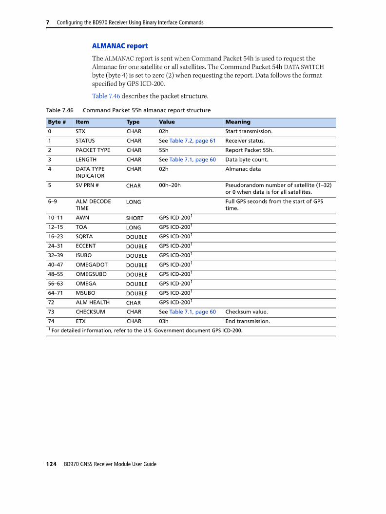
7 Configuring the BD970 Receiver Using Binary Interface Commands
ALMANAC report
The ALMANAC report is sent when Command Packet 54h is used to request the Almanac for one satellite or all satellites. The Command Packet 54h DATA SWITCH byte (byte 4) is set to zero (2) when requesting the report. Data follows the format specified by GPS ICD-200.
Table 7.46 describes the packet structure.
Table 7.46 Command Packet 55h almanac report structure
Byte # Item Type Value Meaning
0 STX CHAR 02h Start transmission.
1 STATUS CHAR See Table 7.2, page 61 Receiver status.
2 PACKET TYPE CHAR 55h Report Packet 55h.
3 LENGTH CHAR See Table 7.1, page 60 Data byte count.
4 DATA TYPE INDICATOR
CHAR 02h Almanac data
5 SV PRN # CHAR 00h–20h Pseudorandom number of satellite (1–32) or 0 when data is for all satellites.
6–9 ALM DECODE TIME
LONG Full GPS seconds from the start of GPS time.
10–11 AWN SHORT GPS ICD-2001
12–15 TOA LONG GPS ICD-2001
16–23 SQRTA DOUBLE GPS ICD-2001
24–31 ECCENT DOUBLE GPS ICD-2001
32–39 ISUBO DOUBLE GPS ICD-2001
40–47 OMEGADOT DOUBLE GPS ICD-2001
48–55 OMEGSUBO DOUBLE GPS ICD-2001
56–63 OMEGA DOUBLE GPS ICD-2001
64–71 MSUBO DOUBLE GPS ICD-2001
72 ALM HEALTH CHAR GPS ICD-2001
73 CHECKSUM CHAR See Table 7.1, page 60 Checksum value.
74 ETX CHAR 03h End transmission.1 For detailed information, refer to the U.S. Government document GPS ICD-200.
124 BD970 GNSS Receiver Module User Guide
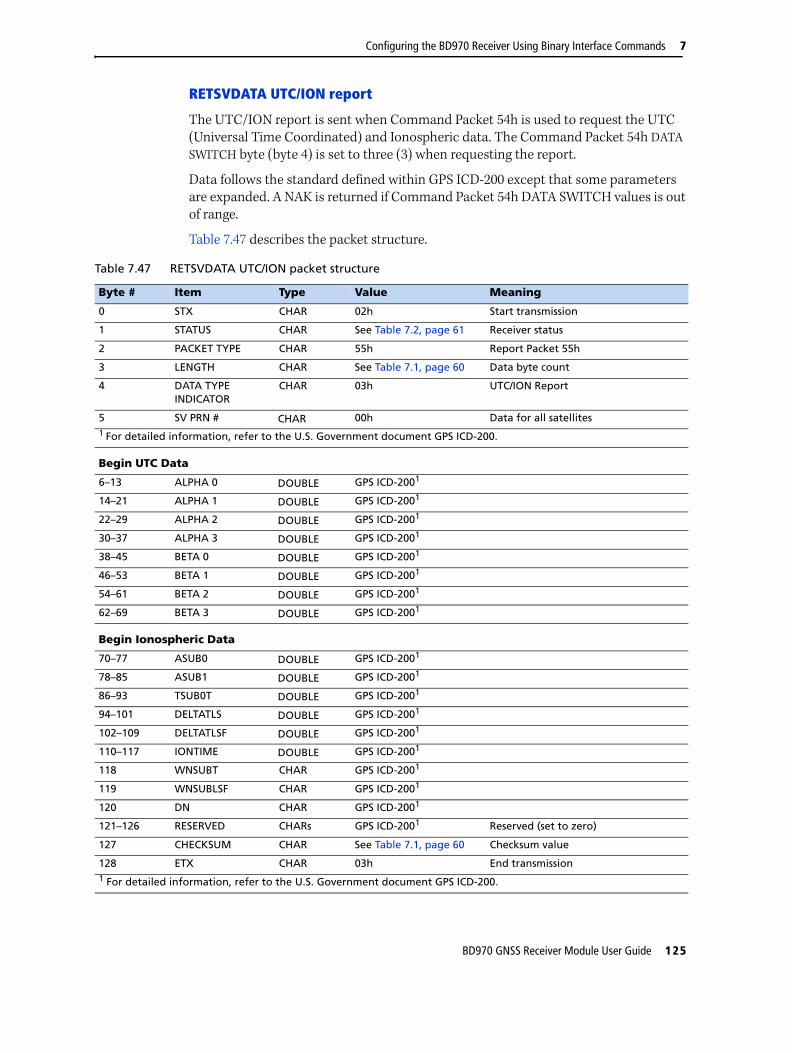
Configuring the BD970 Receiver Using Binary Interface Commands 7
RETSVDATA UTC/ION report
The UTC/ION report is sent when Command Packet 54h is used to request the UTC (Universal Time Coordinated) and Ionospheric data. The Command Packet 54h DATA
SWITCH byte (byte 4) is set to three (3) when requesting the report.
Data follows the standard defined within GPS ICD-200 except that some parameters are expanded. A NAK is returned if Command Packet 54h DATA SWITCH values is out of range.
Table 7.47 describes the packet structure.
Table 7.47 RETSVDATA UTC/ION packet structure
Byte # Item Type Value Meaning
0 STX CHAR 02h Start transmission
1 STATUS CHAR See Table 7.2, page 61 Receiver status
2 PACKET TYPE CHAR 55h Report Packet 55h
3 LENGTH CHAR See Table 7.1, page 60 Data byte count
4 DATA TYPE INDICATOR
CHAR 03h UTC/ION Report
5 SV PRN # CHAR 00h Data for all satellites 1 For detailed information, refer to the U.S. Government document GPS ICD-200.
Begin UTC Data
6–13 ALPHA 0 DOUBLE GPS ICD-2001
14–21 ALPHA 1 DOUBLE GPS ICD-2001
22–29 ALPHA 2 DOUBLE GPS ICD-2001
30–37 ALPHA 3 DOUBLE GPS ICD-2001
38–45 BETA 0 DOUBLE GPS ICD-2001
46–53 BETA 1 DOUBLE GPS ICD-2001
54–61 BETA 2 DOUBLE GPS ICD-2001
62–69 BETA 3 DOUBLE GPS ICD-2001
Begin Ionospheric Data
70–77 ASUB0 DOUBLE GPS ICD-2001
78–85 ASUB1 DOUBLE GPS ICD-2001
86–93 TSUB0T DOUBLE GPS ICD-2001
94–101 DELTATLS DOUBLE GPS ICD-2001
102–109 DELTATLSF DOUBLE GPS ICD-2001
110–117 IONTIME DOUBLE GPS ICD-2001
118 WNSUBT CHAR GPS ICD-2001
119 WNSUBLSF CHAR GPS ICD-2001
120 DN CHAR GPS ICD-2001
121–126 RESERVED CHARs GPS ICD-2001 Reserved (set to zero)
127 CHECKSUM CHAR See Table 7.1, page 60 Checksum value
128 ETX CHAR 03h End transmission1 For detailed information, refer to the U.S. Government document GPS ICD-200.
BD970 GNSS Receiver Module User Guide 125

7 Configuring the BD970 Receiver Using Binary Interface Commands
57h, RAWDATA (Position or real-time survey data report)1
Report Packet 57h is sent in response to one of the following requests:
• Command Packet 56h
• Real-Time Survey Data streaming is enabled in the application file with Command Packet 64h
• A simulated front panel command
A NAK is returned if the Real-Time Survey Data option (RT17) is not installed and the application file is configured to stream real-time survey data.
Report Packet 57h can contain one of the following types of raw data, depending on options selected in Command Packet 56h:
• Expanded Format (*.DAT Record Type 17 style data) raw satellite measurements
• Concise Format (*.DAT Record Type 17 style data) raw satellites measurements
• Position data (*.DAT Record Type 11)
The Expanded and Concise records can also include Enhanced record data, including Real-Time Flags and IODE information if these options are enabled in the application file. For more information, see Report Packet 56h, GETRAW (Position or real-time survey data request), page 67.
Packet paging and measurement counting
The Raw satellite data responses follow either the Expanded or the Concise format and usually exceed the byte limit for RS-232 Serial Interface Specification packets. To overcome the packet size limitation, the data is included in several subpackets called pages. The PAGE INDEX byte (Byte 4) identifies the packet page index and the maximum page index included for the measurement epoch (0 of 2, 1 of 2, 2 of 2).
The first and subsequent packet pages are filled with a maximum of 248 bytes consisting of 4 bytes of page and flag information and 244 bytes of raw satellite data. The raw satellite data is split wherever the 244 byte boundary falls, regardless of internal variable boundaries. Therefore the external device receiving the multiple pages must reconstruct the raw satellite record using the 244 byte pages before parsing the data. This format is maintained for the position record, even though it never extends beyond 244 bytes.
1. This record only contains raw measurement information from the GPS satellites. For raw infor-mation from additional constellations (GLONASS and so on), contact Trimble technical support. SeeTechnical support, page 8.
Packet Flow
Receiver Remote
← Command Packet 56h orRT Survey Data Request or
Front Panel Command
Report Packet 57h or NAK →
126 BD970 GNSS Receiver Module User Guide

Configuring the BD970 Receiver Using Binary Interface Commands 7
Determining the LENGTH byte of records
The total length of the Raw Satellite Data (ignoring the protocol framing and the paging bytes) may be computed as follows:
Expanded Format: LENGTH = 17 + N*48 + M*24 + N*J*12
Concise Format: LENGTH = 17 + N*27 + M*13 + N*J*3
where:
• N is the number of satellites
• M is the number of satellites with L2 data
• J is either 1 if REAL-TIME DATA is ON, or 0 if REAL-TIME DATA is OFF.
Expanded record format
Table 7.48 shows the structure of Report Packet 57h when Expanded Record format is enabled with Command Packet 56h.
Table 7.48 Report Packet 57h structure (expanded format)
Byte # Item Type Value Meaning
0 STX CHAR 02h Start transmission.
1 STATUS CHAR See Table 7.2, page 61 Receiver status.
2 PACKET TYPE CHAR 57h RAWDATA.
3 LENGTH CHAR See Table 7.1, page 60 Data byte count.
4 RECORD TYPE CHAR See Table 7.50, page 130 Raw data record type.
5 PAGING INFO CHAR See Table 7.51, page 130 b7–b4 is the current page number b3–b0 is the total pages in this epoch (1 of 3, 2 of 3, 3 of 3).
6 REPLY # CHAR 00h–FFh Roll-over counter which is incremented with every report but remains constant across pages within one report. This value should be checked on the second and subsequent pages to ensure that report pages are not mismatched with those from another report.
7 FLAGS CHAR See Table 7.52, page 130 Bit 0 must be set to 0 to enable Expanded Record format.
Begin Expanded Format Record Header (17 bytes)
8–15 RECEIVE TIME DOUBLE msecs Receive time within the current GPS week (common to code and phase data).
16–23 CLOCK OFFSET DOUBLE msecs Clock offset value. A value of 0.0 indicates that clock offset is not known.
24 # OF SVS IN RECORD
CHAR Number of SV data blocks included in record.
BD970 GNSS Receiver Module User Guide 127
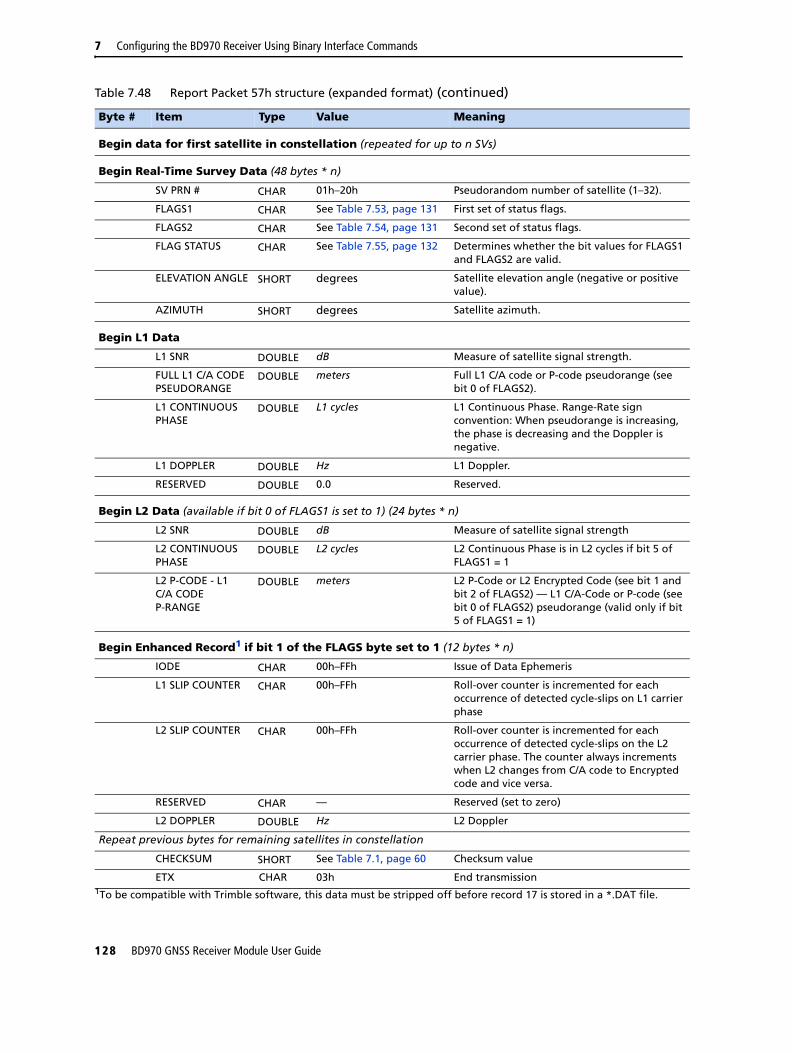
7 Configuring the BD970 Receiver Using Binary Interface Commands
Begin data for first satellite in constellation (repeated for up to n SVs)
Begin Real-Time Survey Data (48 bytes * n)
SV PRN # CHAR 01h–20h Pseudorandom number of satellite (1–32).
FLAGS1 CHAR See Table 7.53, page 131 First set of status flags.
FLAGS2 CHAR See Table 7.54, page 131 Second set of status flags.
FLAG STATUS CHAR See Table 7.55, page 132 Determines whether the bit values for FLAGS1 and FLAGS2 are valid.
ELEVATION ANGLE SHORT degrees Satellite elevation angle (negative or positive value).
AZIMUTH SHORT degrees Satellite azimuth.
Begin L1 Data
L1 SNR DOUBLE dB Measure of satellite signal strength.
FULL L1 C/A CODE PSEUDORANGE
DOUBLE meters Full L1 C/A code or P-code pseudorange (see bit 0 of FLAGS2).
L1 CONTINUOUS PHASE
DOUBLE L1 cycles L1 Continuous Phase. Range-Rate sign convention: When pseudorange is increasing, the phase is decreasing and the Doppler is negative.
L1 DOPPLER DOUBLE Hz L1 Doppler.
RESERVED DOUBLE 0.0 Reserved.
Begin L2 Data (available if bit 0 of FLAGS1 is set to 1) (24 bytes * n)
L2 SNR DOUBLE dB Measure of satellite signal strength
L2 CONTINUOUS PHASE
DOUBLE L2 cycles L2 Continuous Phase is in L2 cycles if bit 5 of FLAGS1 = 1
L2 P-CODE - L1 C/A CODE P-RANGE
DOUBLE meters L2 P-Code or L2 Encrypted Code (see bit 1 and bit 2 of FLAGS2) — L1 C/A-Code or P-code (see bit 0 of FLAGS2) pseudorange (valid only if bit 5 of FLAGS1 = 1)
Begin Enhanced Record1 if bit 1 of the FLAGS byte set to 1 (12 bytes * n)
IODE CHAR 00h–FFh Issue of Data Ephemeris
L1 SLIP COUNTER CHAR 00h–FFh Roll-over counter is incremented for each occurrence of detected cycle-slips on L1 carrier phase
L2 SLIP COUNTER CHAR 00h–FFh Roll-over counter is incremented for each occurrence of detected cycle-slips on the L2 carrier phase. The counter always increments when L2 changes from C/A code to Encrypted code and vice versa.
RESERVED CHAR — Reserved (set to zero)
L2 DOPPLER DOUBLE Hz L2 Doppler
Repeat previous bytes for remaining satellites in constellation
CHECKSUM SHORT See Table 7.1, page 60 Checksum value
ETX CHAR 03h End transmission1To be compatible with Trimble software, this data must be stripped off before record 17 is stored in a *.DAT file.
Table 7.48 Report Packet 57h structure (expanded format) (continued)
Byte # Item Type Value Meaning
128 BD970 GNSS Receiver Module User Guide

Configuring the BD970 Receiver Using Binary Interface Commands 7
Concise record format
Table 7.49 shows the structure of Report Packet 57h when Concise Record format is enabled with Command Packet 56h.
Table 7.49 Report Packet 57h structure (concise format)
Byte # Item Type Value Meaning
0 STX CHAR 02h Start transmission
1 STATUS CHAR See Table 7.2, page 61 Receiver status
2 PACKET TYPE CHAR 57h RAWDATA
3 LENGTH CHAR See Table 7.1, page 60 Data byte count
4 RECORD TYPE CHAR See Table 7.50, page 130 Raw data record type
5 PAGING INFO CHAR See Table 7.51, page 130 b7–b4 is the current page number. b3–b0 is the total pages in this epoch (1 of 3, 2 of 3, 3 of 3).
6 REPLY # CHAR 00h–FFh Roll-over counter is incremented with every report but remains constant across pages within one report. This value should be checked on second and subsequent pages to avoid mismatching report pages with those of another report.
7 FLAGS CHAR See Table 7.52, page 130 Bit 0 must be set to 1 to enable Concise Record format
Begin Concise Record Header (17 bytes)
8–15 RECEIVE TIME DOUBLE msecs Receive time within current GPS week (common to code and phase data)
16–23 CLOCK OFFSET DOUBLE msecs Clock offset value. A value of 0.0 indicates that clock offset is not known.
24 # OF SVS IN RECORD CHAR blocks Number of SV data blocks included in record
Begin data for first satellite in constellation (repeated for up to n SVs)
Begin Real-Time Survey Data (27 bytes * n)
SV PRN # CHAR 01h–20h Satellite pseudorandom number (1–32)
FLAGS1 CHAR See Table 7.53, page 131 First set of satellite status flags
FLAGS2 CHAR See Table 7.54, page 131 Second set of satellite status flags
ELEVATION ANGLE CHAR degrees Satellite elevation angle (negative or positive).
AZIMUTH SHORT degrees Azimuth of satellite
Begin L1 Data
L1 SNR CHAR dB * 4 Measure of satellite signal strength. The value needs to be divided by 4.
FULL L1 C/A CODE PSEUDORANGE
DOUBLE meters Full L1 C/A code or P-code pseudorange (see bit 0 of FLAGS2)
L1 CONTINUOUS PHASE
DOUBLE L1 cycles L1 continuous phase. Range-Rate sign convention: When pseudorange is increasing, the phase is decreasing and the Doppler is negative.
L1 DOPPLER FLOAT Hz L1 Doppler
BD970 GNSS Receiver Module User Guide 129

7 Configuring the BD970 Receiver Using Binary Interface Commands
Begin L2 Data if bit 0 of FLAGS1 set to 1 (13 bytes * n)
L2 SNR CHAR dB * 4 Measure of satellite signal strength. The value needs to be divided by 4.
L2 CONTINUOUS PHASE
DOUBLE L2 cycles L2 continuous phase is in L2 cycles if bit 5 of FLAGS1 = 1.
L2 P-CODE1 - L1 C/A CODE2 P-RANGE
FLOAT meters Valid if bit 5 of FLAGS1 is set to 1.
1 L2 encrypted. See bit 1 and bit 2 of FLAGS2.2 P-code. See bit 0 of FLAGS2.
Begin Enhanced Record1 if bit 1 of the FLAGS byte is set to 1 (3 bytes * n)
IODE CHAR 00h–FFh Issue of Data Ephemeris.
L1 SLIP COUNTER CHAR 00h–FFh Roll-over counter is incremented for each occurrence of detected cycle-slips on L1 carrier phase.
L2 SLIP COUNTER CHAR 00h–FFh Roll-over counter is incremented for each occurrence of detected cycle-slips on the L2 carrier phase. The counter always increments when L2 changes from C/A code to Encrypted code and vice versa.
Repeat previous bytes for remaining satellites in constellation
CHECKSUM SHORT See Table 7.1, page 60 Checksum value
ETX CHAR 03h End transmission1To be compatible with Trimble software, this data must be stripped off before record 17 is stored in a *.DAT file.
Table 7.50 RECORD TYPE byte values
Byte Value Meaning
Dec Hex
0 00h Real-Time Survey Data
1 01h Position Data
Table 7.51 PAGE INFO bit values
Bit Value Meaning
0–3 Total page count
4–7 Current page number
Table 7.52 FLAGS bit values
Bit Meaning
Real-Time Survey Data
0 Raw Data Format
0: Expanded *.DAT Record Type 17 format
1: Concise *.DAT Record Type 17 format
Table 7.49 Report Packet 57h structure (concise format) (continued)
Byte # Item Type Value Meaning
130 BD970 GNSS Receiver Module User Guide
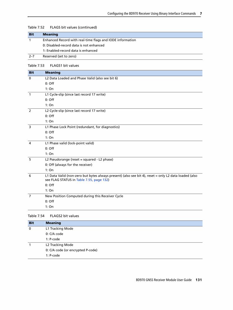
Configuring the BD970 Receiver Using Binary Interface Commands 7
1 Enhanced Record with real-time flags and IODE information
0: Disabled-record data is not enhanced
1: Enabled-record data is enhanced
2–7 Reserved (set to zero)
Table 7.53 FLAGS1 bit values
Bit Meaning
0 L2 Data Loaded and Phase Valid (also see bit 6)
0: Off
1: On
1 L1 Cycle-slip (since last record 17 write)
0: Off
1: On
2 L2 Cycle-slip (since last record 17 write)
0: Off
1: On
3 L1 Phase Lock Point (redundant, for diagnostics)
0: Off
1: On
4 L1 Phase valid (lock-point valid)
0: Off
1: On
5 L2 Pseudorange (reset = squared - L2 phase)
0: Off (always for the receiver)
1: On
6 L1 Data Valid (non-zero but bytes always present) (also see bit 4), reset = only L2 data loaded (also see FLAG STATUS in Table 7.55, page 132)
0: Off
1: On
7 New Position Computed during this Receiver Cycle
0: Off
1: On
Table 7.54 FLAGS2 bit values
Bit Meaning
0 L1 Tracking Mode
0: C/A code
1: P-code
1 L2 Tracking Mode
0: C/A code (or encrypted P-code)
1: P-code
Table 7.52 FLAGS bit values (continued)
Bit Meaning
BD970 GNSS Receiver Module User Guide 131

7 Configuring the BD970 Receiver Using Binary Interface Commands
2 L2 Tracking Encryption Code
0: Off
1: On
3 Filtered L1 Band Pseudorange Corrections
0: Off
1: On
4–7 Reserved (bits set to zero)
Table 7.55 FLAG STATUS bit values
Bit Meaning
0 Validity of FLAGS1 and FLAGS2 Bit Values
0: Bit 6 of FLAGS1 and bit 0–7 of FLAGS2 are undefined
1: Bit 6 of FLAGS1 and bit 0–7 of FLAGS2 are valid (always set for RAWDATA)
2–7 Reserved (bits set to zero)
Table 7.54 FLAGS2 bit values (continued)
Bit Meaning
132 BD970 GNSS Receiver Module User Guide

Configuring the BD970 Receiver Using Binary Interface Commands 7
Position record (Record Type 11)
Table 7.56 shows the structure of Report Packet 57h when the Position Record is enabled with Command Packet 56h.
Position Record Length = 78 + N * 2
where N is the number of satellites.
Table 7.56 Position record (record type 11) structure
Byte # Item Type Value Meaning
0 STX CHAR 02h Start transmission
1 STATUS CHAR See Table 7.2, page 61 Receiver status
2 PACKET TYPE CHAR 57h RAWDATA
3 LENGTH CHAR See Table 7.1, page 60 Data byte count
4 RECORD TYPE CHAR See Table 7.50, page 130 Raw data record type
5 PAGE COUNTER CHAR This byte is split into two sections of 4 bits allowing for 15 pages.
Bits 0-3 : Page total
Bits 4-7 : Current Page number
For example, 0x23 indicates page 2 of 3.
Indicates how many pages there are for this epoch and what this page number is (e.g., 1 of 3, 2 of 3, 3 of 3).
6 REPLY NUMBER CHAR 00h–FFh Roll-over counter which is incremented with every report but remains constant across pages within one report. This value should be checked on the second and subsequent pages to ensure that report pages are not mismatched with those from another report.
7 Record Interpretation Flags
Char Real-Time Survey Data:
• Bit 0: SetConcise format
• Bit 1: SetEnhanced Record with real-time flags and IODE information
• Bits 2-7: Reserved
Position Data, Event Mark, MET3, WAAS, and all other record types: Not Defined
RECORD INTERPRETATION FLAGS indicates special attributes of the record that must be used in parsing values.
Begin Position Record (Record 11) (78 + (nSVs * 2) bytes)
8–15 LATITUDE DOUBLE Latitude in semi-circles
16–23 LONGITUDE DOUBLE Longitude in semi-circles
24–31 ALTITUDE DOUBLE meters Altitude
32–39 CLOCK OFFSET DOUBLE meters Clock offset
40–47 FREQUENCY OFFSET DOUBLE Hz Frequency offset from 1536*1.023 MHz
48–55 PDOP DOUBLE PDOP (dimensionless)
56–63 LATITUDE RATE DOUBLE radians per second Latitude rate
BD970 GNSS Receiver Module User Guide 133

7 Configuring the BD970 Receiver Using Binary Interface Commands
64–71 LONGITUDE RATE DOUBLE radians per second Longitude rate
72–79 ALTITUDE RATE DOUBLE meters per second Altitude rate
80–83 GPS MSEC OF WEEK LONG msecs Position time tag
84 POSITION FLAGS CHAR See Table 7.57, page 134 Position status flags
85 # OF SVS CHAR 00h–0Ch Number of satellites used to compute position solution (0–12)
The next 2 bytes are repeated for each satellite used to compute position
CHANNEL # CHAR Channel used to acquire satellite measurement. Zero is reported for RTK solutions.
PRN # CHAR 01–20h PRN number of satellite (1–32)
CHECKSUM SHORT See Table 7.1, page 60 Checksum value
ETX CHAR 03h End transmission
Table 7.57 POSITION FLAGS bit values
Bit Meaning
0–2 Position flag and position type definition
0: 0-D position fix (clock-only solution) (1+ SVs) (if # of SVs used is non-zero)
1: 1-D position fix (height only with fixed latitude/longitude) (2+ SVs)
2: 2-D position fix (fixed height and clock) (2+ SVs)
3: 2-D position fix (fixed height) (3+ SVs)
4: 3-D solution (4+ SVs)
5: 3D Solution (4+ SVs) Wide Area/Network RTK
3 RTK Solution: if set, position is fixed RTK, else float RTK
0: Floating integer ambiguity
1: Fixed integer ambiguity
4 DGPS Differential Corrections
0: No DGPS corrections are used in position computation
1: DGPS corrections are used to compute position
5 Reserved (set to zero)
6 RTK Solution: if set, position is from RTK (including Location RTK)
0: False
1: True
7 Position Derived While Static (RTK only)
0: False
1: True
Bit combinations
• Bit 4 and 6 are set if the solution type is SBAS
• Bit 5 and 4 are set if the solution type is OmniSTAR HP/XP
Table 7.56 Position record (record type 11) structure (continued)
Byte # Item Type Value Meaning
134 BD970 GNSS Receiver Module User Guide

Configuring the BD970 Receiver Using Binary Interface Commands 7
64h, APPFILE (Application file record report)
Report Packet 64h is sent to the remote device when Command Packet 65h is sent to request a specific application file. Command Packet 65h requests the application file by System File Index.
For more information about BD970 Application Files and guidelines for using application files to control remote devices, see Report Packet 64h, APPFILE (Application file record command), page 68.
The Application File Record Report format is identical to the format used for Command Packet 64h. For more information, see Packet paging, page 69.
Packet Flow
Receiver Remote
← Command Packet 65h
Report Packet 64h →
BD970 GNSS Receiver Module User Guide 135

7 Configuring the BD970 Receiver Using Binary Interface Commands
67h, RETAFDIR (Directory listing report)
Report Packet 67h sends a listing of the application files in the application file directory. The report is requested with Command Packet 66h. For more information, see 66h, GETAFDIR (Application file directory listing request), page 83.
Report Packet 67h can exceed the maximum data byte limit (248 bytes of data) for RS-232 Serial Interface Specification packets, depending on the number of application files stored in memory. Each application file directory entry occupies 16 bytes. Report Packet 67h is divided into subpackets called pages when the data byte limit is exceeded. The PAGE INDEX and MAXIMUM PAGE INDEX bytes are used to account for the pages included in the report (0 of 2, 1 of 2, 2 of 2).
The TX BLOCK IDENTIFIER uses a roll-over counter to assign a transaction number to the report packet pages. The TX BLOCK IDENTIFIER INDEX number is useful for preventing data mismatches when stream synchronization is lost.
Table 7.58 describes the packet structure.
Packet Flow
Receiver Remote
← Command Packet 66h
Report Packet 67h →
Table 7.58 Report packet 67h structure
Byte # Item Type Value Meaning
0 STX CHAR 02h Start transmission.
1 STATUS CHAR See Table 7.2, page 61 Receiver status code.
2 PACKET TYPE CHAR 67h Report Packet 67h.
3 LENGTH CHAR See Table 7.1, page 60 Data byte count.
4 TX BLOCK IDENTIFIER
CHAR 00h–FFh Unique number assigned to every application file transfer.
5 PAGE INDEX CHAR 00h–FFh Page index assigned to packet page.
6 MAXIMUM PAGE INDEX
CHAR 00h–FFh Page index assigned to the last packet page.
Begin Directory List
7 # APP FILES 00h–n Number of application files in directory.1 The Date/Time fields should all be relative to UTC.
First Application File Directory Record
The following record block (bytes 8–23) is repeated for every application file stored in directory. At least one application file exists (SYSTEM FILE INDEX number 0, the Default Application File). The receiver can store at least 10 user-defined application file records.
8 SYSTEM FILE INDEX
CHAR See Table 7.59, page 137
Record number assigned to the file.
9–16 APP FILE NAME CHARs ASCII text Name of application file (8 ASCII characters).
17 CREATION YEAR1 CHAR 00h–FFh Year when file is created. Based on the years since 1900 (1900 = 00).
136 BD970 GNSS Receiver Module User Guide
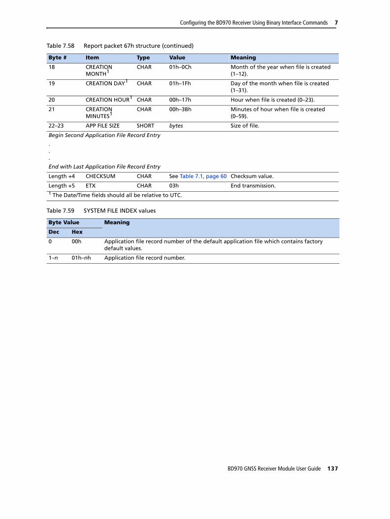
Configuring the BD970 Receiver Using Binary Interface Commands 7
18 CREATION MONTH1
CHAR 01h–0Ch Month of the year when file is created (1–12).
19 CREATION DAY1 CHAR 01h–1Fh Day of the month when file is created (1–31).
20 CREATION HOUR1 CHAR 00h–17h Hour when file is created (0–23).
21 CREATION MINUTES1
CHAR 00h–3Bh Minutes of hour when file is created (0–59).
22–23 APP FILE SIZE SHORT bytes Size of file.
Begin Second Application File Record Entry
.
.
.
End with Last Application File Record Entry
Length +4 CHECKSUM CHAR See Table 7.1, page 60 Checksum value.
Length +5 ETX CHAR 03h End transmission.1 The Date/Time fields should all be relative to UTC.
Table 7.59 SYSTEM FILE INDEX values
Byte Value Meaning
Dec Hex
0 00h Application file record number of the default application file which contains factory default values.
1–n 01h–nh Application file record number.
Table 7.58 Report packet 67h structure (continued)
Byte # Item Type Value Meaning
BD970 GNSS Receiver Module User Guide 137

7 Configuring the BD970 Receiver Using Binary Interface Commands
6Eh, BREAKRET (Break sequence return)
Command Packet 6Eh returns the receivers current serial port communication parameters, receiver version numbers and dates, and communication protocol settings when the remote device sends a 250 millisecond (minimum duration) break sequence.
Sending a break sequence
To initiate a break sequence return, the following events need to occur:
1. The remote device sends a break sequence with a minimum duration of 250 milliseconds to the receiver. For example, pressing [Ctrl]+[Break] from an office computer is equivalent to sending a break sequence.
2. The receiver detects the break signal and responds by setting the communication parameters for the serial port to 9600 baud, 8 data bits, no parity, and 1 stop bit.
3. The receiver outputs an Identity Message through the serial port to the remote device (see Table 7.60).
Table 7.60 describes the structure of Report Packet 6Eh.
Packet Flow
Receiver Remote
← Break sequence
Report Packet 6Eh →
Table 7.60 Report packet 6eh structure
Byte # Item Type Value Meaning
0 STX CHAR 02h Start transmission.
1 STATUS CHAR See Table 7.2, page 61 Receiver status indicator.
2 PACKET TYPE CHAR 6Eh Report Packet 6Eh.
3 LENGTH CHAR See Table 7.1, page 60 Data byte count.
PRODUCT CHARs comma delimited ASCII string
Comma-delimited ASCII string indicating the receiver product family name. For more information, see PRODUCT, page 139.
PORT SETTING CHARs comma delimited ASCII string
Comma-delimited ASCII string indicating the serial port settings and the break sequence acknowledgment code. For more information, see PORT, page 139.
PORT STATUS CHARs ‘FIX’ / ‘ADJ’ FIX: Port settings cannot be changed.
ADJ: Port settings can be changed.
VERSION CHARs comma delimited ASCII string
Comma-delimited ASCII string indicating the software version number and version release date. For more information, see VERSION, page 140.
138 BD970 GNSS Receiver Module User Guide

Configuring the BD970 Receiver Using Binary Interface Commands 7
Identity message format
The following example shows the structure of an Identity Message:
<STX><0><0x6E><93>PRODUCT,BD970;
PORT,1,38400,38400,8,1,N,F;
VERSION,4.30, 4/14/10,,;
COMM,DCOL,NMEA;<CHECKSUM><ETX>
Note – The previous example shows the strings on separate lines for clarity, but the actual message is one continuous string of characters.
Detailed information about the four parameter strings is described in the following sections.
PRODUCT
For the receiver, the PRODUCT string is always set to BD970. The string always begins with the word PRODUCT, followed by a comma, followed by the word BD970, and terminated with a semicolon as in the following example:
PRODUCT,BD970;
PORT
The PORT parameter is a comma-delimited string of ASCII characters describing the current input baud rate, output baud rate, data bits, stop bits, parity, and the break sequence status acknowledgment. The syntax of the comma delimited string is shown below:
PORT,input baud rate,output baud rate,data bits,stop bits, parity,boolean acknowledgement;
The string always begins with the word PORT, and the end of the string is always terminated with a semicolon character. Commas are used to delimit the other fields within the string.
COMM PROTOCOL
CHARs comma delimited ASCII string
Comma-delimited ASCII string indicating the communication protocols supported on serial portm serial number, and Ethernet IP address. For more information, see COMM, page 140.
SERIAL: Receiver serial number
NOT SET’ETHIP: Receiver Ethernet IP address in xxx.xxx.xxx.xxx format or 0.0.0.0 if not found.
CHECKSUM CHAR See Table 7.1, page 60 Checksum value.
ETX CHAR 03h End transmission.
Table 7.60 Report packet 6eh structure (continued)
Byte # Item Type Value Meaning
BD970 GNSS Receiver Module User Guide 139
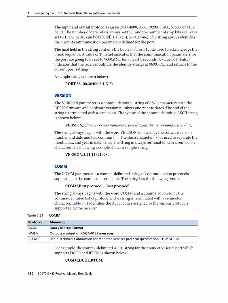
7 Configuring the BD970 Receiver Using Binary Interface Commands
The input and output protocols can be 2400, 4800, 9600, 19200, 38400, 57600, or 115k baud. The number of data bits is always set to 8, and the number of stop bits is always set to 1. The parity can be O (Odd), E (Even), or N (None). The string always identifies the current communication parameters defined for the port.
The final field in the string contains the boolean (T or F) code used to acknowledge the break sequence. A value of T (True) indicates that the communication parameters for the port are going to be set to 9600,8,N,1 for at least 5 seconds. A value of F (False) indicates that the receiver outputs the identity strings at 9600,8,N,1 and returns to the current port settings.
A sample string is shown below:
PORT,38400,38400,8,1,N,F;
VERSION
The VERSION parameter is a comma-delimited string of ASCII characters with the BD970 firmware and hardware version numbers and release dates. The end of the string is terminated with a semicolon. The syntax of the comma-delimited ASCII string is shown below:
VERSION,software version number,version date,hardware version,version date;
The string always begins with the word VERSION, followed by the software version number and date and two commas ( , ). The slash character ( / ) is used to separate the month, day, and year in date fields. The string is always terminated with a semicolon character. The following example shows a sample string:
VERSION,2.21,11/21/98,,;
COMM
The COMM parameter is a comma-delimited string of communication protocols supported on the connected serial port. The string has the following syntax:
COMM,first protocol,...last protocol;
The string always begins with the word COMM and a comma, followed by the comma-delimited list of protocols. The string is terminated with a semicolon character. Table 7.61 identifies the ASCII codes assigned to the various protocols supported by the receiver.
For example, the comma-delimited ASCII string for the connected serial port which supports DCOL and RTCM is shown below:
COMM,DCOL,RTCM;
Table 7.61 COMM
Protocol Meaning
DCOL Data Collector Format
NMEA Outputs a subset of NMEA-0183 messages
RTCM Radio Technical Commission for Maritime Services protocol specification RTCM SC-104
140 BD970 GNSS Receiver Module User Guide

Configuring the BD970 Receiver Using Binary Interface Commands 7
82h, SCRDUMP (Screen dump)
Command Packet 82h has two forms—a command packet and report packet. Both packets are assigned the same hexadecimal code (82h). For more information, see 82h, SCRDUMP (Screen dump request), page 88.
Report Packet 82h is sent in response to Command Packet 82h. The receiver generates an ASCII representation (a dump) of a BD970 display screen, and sends the dump to the remote device in Report Packet 82h. Table 7.62 shows the packet structure.
Packet Flow
Receiver Remote
← Command Packet 82h
Report Packet 82h →
Table 7.62 Report packet 82h structure
Byte # Item Type Value Meaning
0 STX CHAR 02h Start transmission
1 STATUS CHAR See Table 7.2, page 61 Receiver status code
2 PACKET TYPE CHAR 82h Report Packet 82h
3 LENGTH CHAR A1h Data byte count
4–163 ASCII DATA CHARs ASCII data
164 CURSOR POSITION CHAR Position of the cursor
165 CHECKSUM CHAR See Table 7.1, page 60 Checksum value
166 ETX CHAR 03h End transmission
BD970 GNSS Receiver Module User Guide 141

7 Configuring the BD970 Receiver Using Binary Interface Commands
142 BD970 GNSS Receiver Module User Guide

C H A P T E R
8
Default Settings 8In this chapter:
Default receiver settings
All settings are stored in application files. The default application file, Default.cfg, is stored permanently in the receiver, and contains the factory default settings. Whenever the receiver is reset to its factory defaults, the current settings (stored in the current application file, Current.cfg) are reset to the values in the default application file.
BD970 GNSS Receiver Module User Guide 143

8 Default Settings
Default receiver settingsThese settings are defined in the default application file.
Function Factory default
SV Enable All SVs enabled
General Controls: Elevation mask 10°
PDOP mask 99
RTK positioning mode Low Latency
Motion Kinematic
Ports: Baud rate 38,400
Format 8-None-1
Flow control None
Input Setup: Station Any
NMEA/ASCII (all supported messages)
All ports Off
Streamed output All types OffOffset = 00
RT17/Binary All ports Off
Reference position: Latitude 0°
Longitude 0°
Altitude 0.00 m HAE (Height above ellipsoid)
Antenna: Type Unknown
Height (true vertical) 0.00 m
Measurement method Antenna Phase Center
1 PPS Disabled
144 BD970 GNSS Receiver Module User Guide

C H A P T E R
9
Specifications 9In this chapter:
Physical specifications
Performance specifications
Electrical specifications
Communication specifications
This chapter details the specifications for the receiver.
Specifications are subject to change without notice.
BD970 GNSS Receiver Module User Guide 145

9 Specifications
Physical specifications
Performance specifications
Feature Specification
Dimensions (L x W x H) 100 mm x 60 mm x 11.6 mm
Temperature Operating
Storage
–40 °C to +75 °C (–40 °F to +167 °F)
–55 °C to +85 °C (–40 °F to +176 °F)
Vibration MIL810F, tailored
Random 6.2 gRMS operatingRandom 8 gRMS survival
Mechanical shock MIL810D±40 g operating±75 g survival
I/O Connector 24-pin header + 6-pin header (Samtec TMM-112-03-L-D)
Antenna Connector MMCX receptacle (Huber-Suhner 82MMCX-50-0-1/111); mating connectors are MMCX plug (Suhner 11MMCX-50-2-1C) or right-angle plug (Suhner 16MMCX-50-2-1C, or 16MMCX-50-2-10)
Feature Specification
Measurements • 220 Channels:
– GPS: Simultaneous L1 C/A, L2E, L2C, L5
– GLONASS: Simultaneous L1 C/A, L1 P, L2 C/A (GLONASS M Only), L2 P
– SBAS: Simultaneous L1 C/A, L5
– GIOVE-A: Simultaneous L1 BOC, E5A, E5B, E5AltBOC Footnotes: 1
– GIOVE-B: Simultaneous L1 CBOC, E5A, E5B, E5AltBOC Footnotes: 1
– GALILEO: Disabled Footnotes: 2
• Advanced Trimble Maxwell 6 Custom Survey GNSS Technology• High precision multiple correlator for GNSS pseudorange measurements• Unfiltered, unsmoothed pseudorange measurements data for low noise, low
multipath error, low time domain correlation and high dynamic response
• Very low noise GNSS carrier phase measurements with <1 mm precision in a 1 Hz bandwidth
• Signal-to-Noise ratios reported in dB-Hz• Proven Trimble low elevation tracking technology
Code differential GPS positioning Footnotes: 3
3D Typically, <1 m
SBAS (WAAS/EGNOS/MSAS)
Horizontal accuracy Footnotes: 4 Vertical accuracy Footnotes: 4
Typically <1 m
Typically <5 m
146 BD970 GNSS Receiver Module User Guide

Specifications 9
Electrical specifications
Communication specifications
RTK positioningHorizontal accuracyVertical accuracy
±(8 mm + 1 ppm) RMS±(15 mm + 1 ppm) RMS
Initialization timeInitialization reliability Footnotes: 5
Typically, less than 10 secondsTypically >99.9%
Footnotes:1. Galileo GIoVE-A and GIoVE-B test satellite support uses information that is unrestricted in the public domain
and is intended for signal evaluation and test purposes.
2. The hardware is compliant to Galileo OS SIS ICD, Issue 1, Rev. 1, Sep 2010. Commercial sale of Galileo technology requires Trimble to acquire a Commercial license from the European Union. At the time of publishing there is no process for obtaining a license. Therefore to comply with the ICD Copyright/IPR terms all Galileo firmware/hardware functionality is disabled. Depending on the terms of the license an upgrade to full Galileo (L1 CBOC, E5A, E5B, E5AltBOC) may be offered. This will require an additional fee.
3. Accuracy and reliability may be subject to anomalies such as multipath, obstructions, satellite geometry, and atmospheric conditions. Always follow recommended practices.
4. Depends on WAAS, EGNOS, and MSAS system performance.5. May be affected by atmospheric conditions, signal multipath, and satellite geometry. Initialization reliability is
continuously monitored to ensure highest quality.
Feature Specification
Power 3.3 DCV +5%/-3%
Power consumption Typically, 1.4W (L1/L2 GPS)Typically, 1.5W (L1/L2 GPS and G1/G2 GLONASS)
Feature Specification
Communications
1 LAN port • Supports links to 10BaseT/100BaseT networks. • All functions are performed through a single IP address simultaneously—
including web interface access and data streaming.
3 x RS232 ports Baud rates up to 115,200.
Receiver position update rate
1 Hz, 2 Hz, 5 Hz, 10 Hz, 20 Hz, and 50 Hz positioning
Correction data input CMR, CMR+, RTCM 2.0 (select RTCM 2.1), RTCM 2.1–2.3, RTCM 3.0, 3.1.
Correction data output CMR, CMR+, RTCM 2.0 DGPS (select RTCM 2.1), RTCM 2.1–2.3, RTCM 3.0, 3.1.
Data outputs 1PPS, NMEA, Binary GSOF, ASCII Time Tags.
Event Marker Input support
Feature Specification
BD970 GNSS Receiver Module User Guide 147

9 Specifications
148 BD970 GNSS Receiver Module User Guide

A P P E N D I X
A
NMEA-0183 Output AIn this appendix:
NMEA-0183 message overview
Common message elements
NMEA messages
This appendix describes the formats of the subset of NMEA-0183 messages that are available for output by the receivers. For a copy of the NMEA-0183 Standard, go to the National Marine Electronics Association website at www.nmea.org.
To enable NMEA messages, see the configuration methods described in:
• Chapter 5, Configuring the BD970 Receiver Using Trimble Software Utilities
• Chapter 6, Configuring the BD970 Receiver Using a Web Browser
• Chapter 7, Configuring the BD970 Receiver Using Binary Interface Commands
BD970 GNSS Receiver Module User Guide 149

A NMEA-0183 Output
NMEA-0183 message overviewWhen NMEA-0183 output is enabled, a subset of NMEA-0183 messages can be output to external instruments and equipment connected to the receiver serial ports. These NMEA-0183 messages let external devices use selected data collected or computed by the GPS receiver.
All messages conform to the NMEA-0183 version 3.01 format. All begin with $ and end with a carriage return and a line feed. Data fields follow comma (,) delimiters and are variable in length. Null fields still follow comma (,) delimiters but contain no information.
An asterisk (*) delimiter and checksum value follow the last field of data contained in an NMEA-0183 message. The checksum is the 8-bit exclusive of all characters in the message, including the commas between fields, but not including the $ and asterisk delimiters. The hexadecimal result is converted to two ASCII characters (0–9, A–F). The most significant character appears first.
The following table summarizes the set of NMEA messages supported by the receiver, and shows the page that contains detailed information about each message.
Message Function Page
ADV Position and Satellite information for RTK network operations 152
GBS GNSS Satellite Fault Detection 153
GGA Time, position, and fix related data 155
GLL Position data 156
GRS GPS Range Residuals 157
GSA GPS DOP and active satellites 158
GST Position error statistics 159
GSV Number of SVs in view, PRN, elevation, azimuth, and SNR 160
HDT Heading from True North 161
PTNL,AVR Time, yaw, tilt, range, mode, PDOP, and number of SVs for Moving Baseline RTK
162
PTNL,BPQ Base station position and position quality indicator 163
PTNL,GGK Time, position, position type and DOP values 164
PTNL,PJK Local coordinate position output 165
PTNL,VGK Time, locator vector, type and DOP values 166
PTNL,VHD Heading Information 167
RMC Position, Velocity, and Time 168
ROT Rate of turn 169
VTG Actual track made good and speed over ground 170
ZDA UTC day, month, and year, and local time zone offset 171
150 BD970 GNSS Receiver Module User Guide

NMEA-0183 Output A
Common message elementsEach message contains:
• a message ID consisting of $GP followed by the message type. For example, the message ID of the GGA message is $GPGGA.
• a comma
• a number of fields, depending on the message type, separated by commas
• an asterisk
• a checksum value
Below is an example of a simple message with a message ID ($GPGGA), followed by 13 fields and a checksum value:
$GPGGA,172814.0,3723.46587704,N,12202.26957864,W,2,6,1.2,18.893,M,-25.669,M,2.0,0031*4F
Message values
NMEA messages that the receiver generates contains the following values.
Latitude and longitude
Latitude is represented as ddmm.mmmm and longitude is represented as dddmm.mmmm, where:
• dd or ddd is degrees
• mm.mmmm is minutes and decimal fractions of minutes
Direction
Direction (north, south, east, or west) is represented by a single character: N, S, E, or W.
Time
Time values are presented in Universal Time Coordinated (UTC) and are represented as hhmmss.cc, where:
• hh is hours, from 00 through 23
• mm is minutes
• ss is seconds
• cc is hundredths of seconds
NMEA messagesWhen NMEA-0183 output is enabled, the following messages can be generated.
BD970 GNSS Receiver Module User Guide 151

A NMEA-0183 Output
ADV Position and Satellite information for RTK network operations
An example of the ADV message string is shown below. Table A.1 and Table A.2 describe the message fields. The messages alternate between subtype 110 and 120.
$PGPPADV,110,39.88113582,-105.07838455,1614.125*1M
$PGPPADV,120,21,76.82,68.51,29,20.66,317.47,28,52.38,276.81,22,42.26,198.96*5D
Table A.1 ADV subtype 110 message fields
Field Meaning
0 Message ID $PPGPADV
1 Message sub-type 110
2 Latitude
3 Longitude
4 Ellipsoid height
6 Elevation of second satellite, in degrees, 90° maximum
7 Azimuth of second satellite, degrees from True North, 000° through 359°
8 The checksum data, always begins with *
Table A.2 ADV subtype 120 message fields
Field Meaning
0 Message ID $PPGPADV
1 Message sub-type 120
2 First SV PRN number
3 Elevation of first satellite, in degrees, 90° maximum
4 Azimuth of first satellite, degrees from True North, 000° through 359°
5 Second SV PRN number
6 Elevation of second satellite, in degrees, 90° maximum
7 Azimuth of second satellite, degrees from True North, 000° through 359°
8 The checksum data, always begins with *
152 BD970 GNSS Receiver Module User Guide

NMEA-0183 Output A
GBS GNSS satellite fault detection
The GBS message supports the Receiver Autonomous Integrity Monitoring (RAIM).
Given that a GNSS receiver tracks enough satellites to perform integrity checks of the positioning quality of the position solution, a message is needed to report the output of this process to other systems to advise the system user. With RAIM in the GNSS receiver, the receiver can isolate faults to individual satellites, and omit them from its position and velocity calculations. In addition, the GNSS receiver can still track the satellite, and easily judge when it is back within tolerance. This message reports this RAIM information.
To perform this integrity function, the GNSS receiver must have at least two observables in addition to the minimum required for navigation. Normally, these observables take the form of additional redundant satellites. If only GPS, GLONASS or so on is used for the reported position solution, the talker ID is GP, GL, or as appropriate, and the errors pertain to the individual system. If satellites from multiple systems are used to obtain the reported position solution, the talker ID is GN and the errors pertain to the combined solution.
An example of the GBS message string is shown below. Table A.20 describes the message fields.
$GBS,hhmmss.ss,x.x,x.x,x.x,xx,x.x,x.x,x.x*hh<CR><LF>
Notes:
1. Expected error in meters due to bias, with noise = 0
2. To avoid possible confusion caused by repetition of satellite ID numbers when using multiple satellite systems, the following convention applies:
Table A.3 GBS message fields
Field Meaning
0 Message ID $GBS
1 UTC time of GGA or GNS fix associated with this message
2 Expected error in latitude1
3 Expected error in longitude1
4 Expected error in altitude1
5 ID number2 of most likely failed satellite
6 Probability of missed detection for most likely failed satellite
7 Estimate of bias in meters on most likely failed satellite
8 Standard deviation of bias estimate
Satellite system
ID numbers
GPS PRN numbers (1-32)
BD970 GNSS Receiver Module User Guide 153

A NMEA-0183 Output
WAAS 3-64
GLONASS 65-96
64+satellite slot number: 1-24 = the full GLONASS constellation of 24 satellites. This gives a range of 65 through 88.88 through 99 are available if slot numbers above 24 are allocated to on-orbit spares.
Satellite system
ID numbers
154 BD970 GNSS Receiver Module User Guide
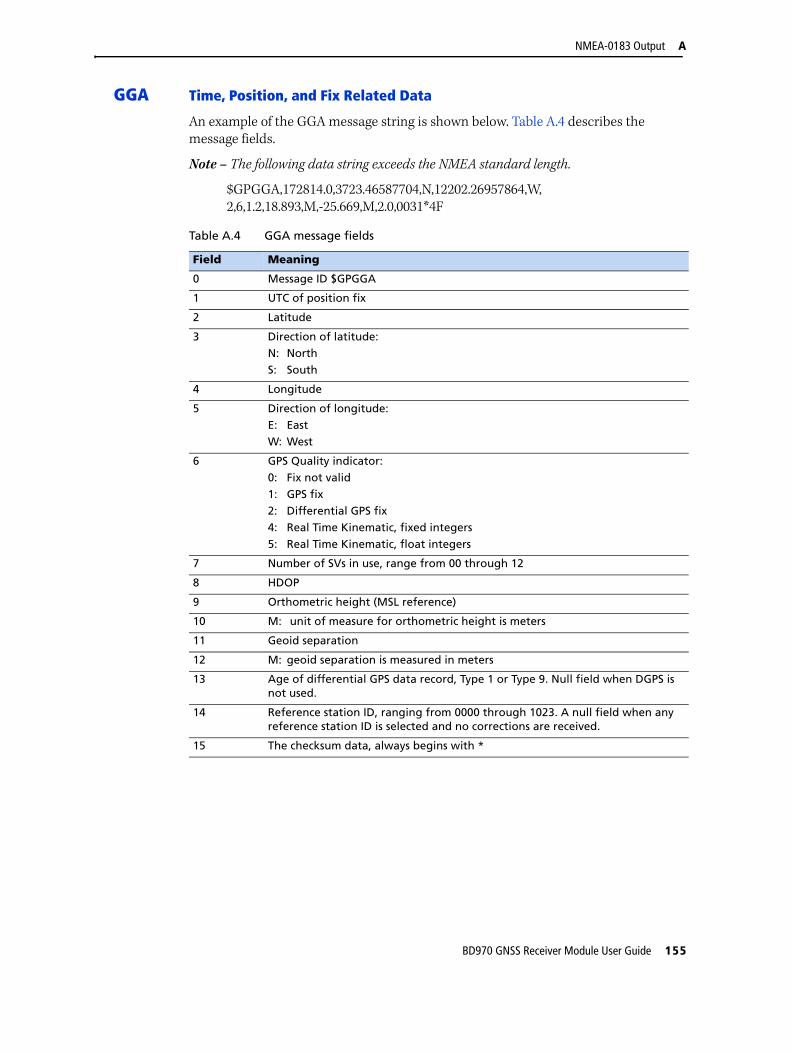
NMEA-0183 Output A
GGA Time, Position, and Fix Related Data
An example of the GGA message string is shown below. Table A.4 describes the message fields.
Note – The following data string exceeds the NMEA standard length.
$GPGGA,172814.0,3723.46587704,N,12202.26957864,W,2,6,1.2,18.893,M,-25.669,M,2.0,0031*4F
Table A.4 GGA message fields
Field Meaning
0 Message ID $GPGGA
1 UTC of position fix
2 Latitude
3 Direction of latitude:N: NorthS: South
4 Longitude
5 Direction of longitude:E: EastW: West
6 GPS Quality indicator:0: Fix not valid
1: GPS fix2: Differential GPS fix4: Real Time Kinematic, fixed integers
5: Real Time Kinematic, float integers
7 Number of SVs in use, range from 00 through 12
8 HDOP
9 Orthometric height (MSL reference)
10 M: unit of measure for orthometric height is meters
11 Geoid separation
12 M: geoid separation is measured in meters
13 Age of differential GPS data record, Type 1 or Type 9. Null field when DGPS is not used.
14 Reference station ID, ranging from 0000 through 1023. A null field when any reference station ID is selected and no corrections are received.
15 The checksum data, always begins with *
BD970 GNSS Receiver Module User Guide 155

A NMEA-0183 Output
GLL Position data: position fix, time of position fix, and status
An example of the GLL message string is shown below. Table A.20 describes the message fields.
$GPGLL,3723.4543,N,12202.2696,W,151933,A*3E
Table A.5 GLL message fields
Field Meaning
0 Message ID $GPGLL
1 Latitude in dd mm,mmmm format (0-7 decimal places)
2 Direction of latitude N: North S: South
3 Longitude in ddd mm,mmmm format (0-7 decimal places)
4 Direction of longitude E: East W: West
5 UTC of position in hhmmss.ss format
6 Fixed text "A" shows that data is valid
156 BD970 GNSS Receiver Module User Guide

NMEA-0183 Output A
GRS GRS range residuals
The GRS message is used to support the Receiver Autonomous Integrity Monitoring (RAIM).
Note – Because the contents of this NMEA message do not change significantly during a one-second interval, the receiver outputs this message at a maximum rate of 1 Hz.
An example of the GRS message string is shown below. Table A.20 describes the message fields.
$GPGRS,220320.0,0,-0.8,-0.2,-0.1, -0.2,0.8,0.6,,,,,,,*55
Table A.6 GRS message fields
Field Meaning
0 Message ID $GPGRS
1 UTC time of GGA position fix
2 Residuals
0: Residuals used to calculate position given in the matching GGA line1: Residuals recomputed after the GGA position was computed
3-14 Range residuals for satellites used in the navigation solution, in meters
BD970 GNSS Receiver Module User Guide 157

A NMEA-0183 Output
GSA GPS DOP and active satellites
An example of the GSA message string is shown below. Table A.7 describes the message fields.
$GPGSA,<1>,<2>,<3>,<3>,,,,,<3>,<3>,<3>,<4>,<5>,<6>*<7><CR><LF>
Table A.7 GSA message fields
Field Meaning
0 Message ID $GPGSA
1 Mode 1, M = manual, A = automatic
2 Mode 2, Fix type, 1 = not available, 2 = 2D, 3 = 3D
3 PRN number, 01 through 32, of satellite used in solution, up to 12 transmitted
4 PDOP-Position dilution of precision, 0.5 through 99.9
5 HDOP-Horizontal dilution of precision, 0.5 through 99.9
6 VDOP-Vertical dilution of precision, 0.5 through 99.9
7 The checksum data, always begins with *
158 BD970 GNSS Receiver Module User Guide

NMEA-0183 Output A
GST Position Error Statistics
An example of the GST message string is shown below. Table A.8 describes the message fields.
$GPGST,172814.0,0.006,0.023,0.020,273.6,0.023,0.020,0.031*6A
Table A.8 GST message fields
Field Meaning
0 Message ID $GPGST
1 UTC of position fix
2 RMS value of the pseudorange residuals; includes carrier phase residuals during periods of RTK(float) and RTK(fixed) processing
3 Error ellipse semi-major axis 1 sigma error, in meters
4 Error ellipse semi-minor axis 1 sigma error, in meters
5 Error ellipse orientation, degrees from true north
6 Latitude 1 sigma error, in meters
7 Longitude 1 sigma error, in meters
8 Height 1 sigma error, in meters
9 The checksum data, always begins with *
BD970 GNSS Receiver Module User Guide 159

A NMEA-0183 Output
GSV Satellite Information
The GSV message string identifies the number of SVs in view, the PRN numbers, elevations, azimuths, and SNR values. An example of the GSV message string is shown below. Table A.9 describes the message fields.
$GPGSV,4,1,13,02,02,213,,03,-3,000,,11,00,121,,14,13,172,05*67
Table A.9 GSV message fields
Field Meaning
0 Message ID $GPGSV
1 Total number of messages of this type in this cycle
2 Message number
3 Total number of SVs visible
4 SV PRN number
5 Elevation, in degrees, 90° maximum
6 Azimuth, degrees from True North, 000° through 359°
7 SNR, 00–99 dB (null when not tracking)
8–11 Information about second SV, same format as fields 4 through 7
12–15 Information about third SV, same format as fields 4 through 7
16–19 Information about fourth SV, same format as fields 4 through 7
20 The checksum data, always begins with *
160 BD970 GNSS Receiver Module User Guide

NMEA-0183 Output A
HDT Heading from True North
The HDT string is shown below, and Table A.10 describes the message fields.
$GPHDT,123.456,T*00
Table A.10 Heading from true north fields
Field Meaning
0 Message ID $GPHDT
1 Heading in degrees
2 T: Indicates heading relative to True North
3 The checksum data, always begins with *
BD970 GNSS Receiver Module User Guide 161

A NMEA-0183 Output
PTNL,AVRTime, Yaw, Tilt, Range for Moving Baseline RTK
The PTNL,AVR message string is shown below, and Table A.11 describes the message fields.
$PTNL,AVR,181059.6,+149.4688,Yaw,+0.0134,Tilt,,,60.191,3,2.5,6*00
Table A.11 AVR message fields
Field Meaning
0 Message ID $PTNL,AVR
1 UTC of vector fix
2 Yaw angle in degrees
3 Yaw
4 Tilt angle in degrees
5 Tilt
6 Reserved
7 Reserved
8 Range in meters
9 GPS quality indicator:0: Fix not available or invalid1: Autonomous GPS fix2: Differential carrier phase solution RTK (Float)3: Differential carrier phase solution RTK (Fix)4: Differential code-based solution, DGPS
10 PDOP
11 Number of satellites used in solution
12 The checksum data, always begins with *
162 BD970 GNSS Receiver Module User Guide

NMEA-0183 Output A
PTNL,BPQBase station position and quality indicator
This message describes the base station position and its quality. It is used when the moving base antenna position and quality are required on one serial port (along with a heading message) from a receiver in heading mode, typically the SPS551H.
The PTNL,BPQ message string is shown below, and Table A.12 describes the message fields.
$PTNL,BPQ,224445.06,021207,3723.09383914,N,12200.32620132,W,EHT-5.923,M,5*
Table A.12 BPQ message fields
Field Meaning
0 Talker ID
1 BPQ
2 UTC time of position fix, in hhmmss.ss format. Hours must be two numbers, so may be padded, for example, 7 is shown as 07.
3 UTC date of position fix, in ddmmyy format. Day must be two numbers, so may be padded, for example, 8 is shown as 08.
4 Latitude, in degrees and decimal minutes (ddmm.mmmmmmm)
5 Direction of latitude:N: North
S: South
6 Longitude, in degrees and decimal minutes (dddmm.mmmmmmm). Should contain 3 digits of ddd.
7 Direction of longitude:E: East
W: West
8 Height
Ellipsoidal height of fix (antenna height above ellipsoid). Must start with EHT.
9 M: ellipsoidal height is measured in meters
10 GPS quality indicator:0: Fix not available or invalid
1: Autonomous GPS fix2: Differential SBAS4: RTK Fixed
5: OmniSTAR XP, OmniSTAR HP, Float RTK, or Location RTK
11 The checksum data, always begins with *
BD970 GNSS Receiver Module User Guide 163

A NMEA-0183 Output
PTNL,GGKTime, Position, Position Type, DOP
An example of the PTNL,GGK message string is shown below. Table A.13 describes the message fields.
$PTNL,GGK,172814.00,071296,3723.46587704,N,12202.26957864,W,3,06,1.7,EHT-6.777,M*48
Note – The PTNL,GGK message is longer than the NMEA-0183 standard of 80 characters.
Table A.13 PTNL,GGK message fields
Field Meaning
0 Message ID $PTNL,GGA
1 UTC of position fix
2 Date
3 Latitude
4 Direction of latitude:
N: NorthS: South
5 Longitude
6 Direction of Longitude:
E: EastW: West
7 GPS Quality indicator:0: Fix not available or invalid1: Autonomous GPS fix
2: RTK float solution3: RTK fix solution4: Differential, code phase only solution (DGPS)
5: SBAS solution – WAAS, EGNOS, MSAS6: RTK Float 3D Network solution7: RTK Fixed 3D Network solution
8: RTK Float 2D in a Network solution9: RTK Fixed 2D Network solution10: OmniSTAR HP/XP solution
11: OmniSTAR VBS solution
8 Number of satellites in fix
9 DOP of fix
10 Ellipsoidal height of fix
11 M: ellipsoidal height is measured in meters
12 The checksum data, always begins with *
164 BD970 GNSS Receiver Module User Guide
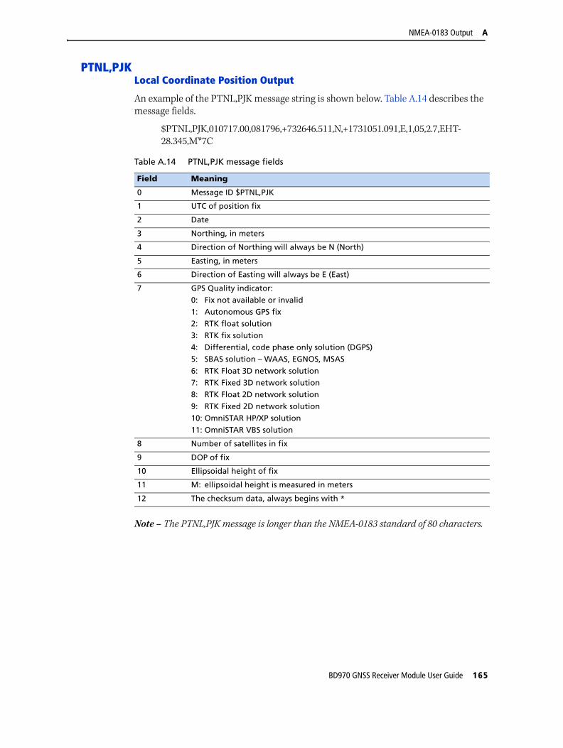
NMEA-0183 Output A
PTNL,PJKLocal Coordinate Position Output
An example of the PTNL,PJK message string is shown below. Table A.14 describes the message fields.
$PTNL,PJK,010717.00,081796,+732646.511,N,+1731051.091,E,1,05,2.7,EHT-28.345,M*7C
Note – The PTNL,PJK message is longer than the NMEA-0183 standard of 80 characters.
Table A.14 PTNL,PJK message fields
Field Meaning
0 Message ID $PTNL,PJK
1 UTC of position fix
2 Date
3 Northing, in meters
4 Direction of Northing will always be N (North)
5 Easting, in meters
6 Direction of Easting will always be E (East)
7 GPS Quality indicator:
0: Fix not available or invalid1: Autonomous GPS fix2: RTK float solution
3: RTK fix solution4: Differential, code phase only solution (DGPS)5: SBAS solution – WAAS, EGNOS, MSAS
6: RTK Float 3D network solution7: RTK Fixed 3D network solution8: RTK Float 2D network solution
9: RTK Fixed 2D network solution10: OmniSTAR HP/XP solution11: OmniSTAR VBS solution
8 Number of satellites in fix
9 DOP of fix
10 Ellipsoidal height of fix
11 M: ellipsoidal height is measured in meters
12 The checksum data, always begins with *
BD970 GNSS Receiver Module User Guide 165

A NMEA-0183 Output
PTNL,VGKVector Information
An example of the PTNL,VGK message string is shown below. Table A.15 describes the message fields.
$PTNL,VGK,160159.00,010997,-0000.161,00009.985,-0000.002,3,07,1,4,M*0B
Table A.15 PTNL,VGK message fields
Field Meaning
0 Message ID $PTNL,VGK
1 UTC of vector in hhmmss.ss format
2 Date in mmddyy format
3 East component of vector, in meters
4 North component of vector, in meters
5 Up component of vector, in meters
6 GPS Quality indicator:0: Fix not available or invalid
1: Autonomous GPS fix2: RTK float solution3: RTK fix solution
4: Differential, code phase only solution (DGPS)5: SBAS solution – WAAS, EGNOS, MSAS6: RTK Float 3D network solution
7: RTK Fixed 3D network solution8: RTK Float 2D network solution9: RTK Fixed 2D network solution
10: OmniSTAR HP/XP solution11: OmniSTAR VBS solution
7 Number of satellites if fix solution
8 DOP of fix
9 M: Vector components are in meters
10 The checksum data, always begins with *
166 BD970 GNSS Receiver Module User Guide

NMEA-0183 Output A
PTNL,VHDHeading information
An example of the PTNL,VHD message string is shown below. Table A.16 describes the message fields.
$PTNL,VHD,030556.00,093098,187.718,-22.138,-76.929,-5.015,0.033,0.006,3,07,2.4,M*22
Table A.16 PTNL,VHD message fields
Field Meaning
0 Message ID $PTNL,VHD
1 UTC of position in hhmmss.ss format
2 Date in mmddyy format
3 Azimuth
4 ΔAzimuth/ΔTime
5 Vertical Angle
6 ΔVertical/ΔTime
7 Range
8 ΔRange/ΔTime
9 GPS Quality indicator:0: Fix not available or invalid1: Autonomous GPS fix
2: RTK float solution3: RTK fix solution4: Differential, code phase only solution (DGPS)
5: SBAS solution – WAAS, EGNOS, MSAS6: RTK Float 3D network solution7: RTK Fixed 3D network solution
8: RTK Float 2D network solution9: RTK Fixed 2D network solution10: OmniSTAR HP/XP solution
11: OmniSTAR VBS solution
10 Number of satellites used in solution
11 PDOP
12 The checksum data, always begins with *
BD970 GNSS Receiver Module User Guide 167

A NMEA-0183 Output
RMC Position, Velocity, and Time
The RMC string is shown below, and Table A.17 describes the message fields.
$GPRMC,123519,A,4807.038,N,01131.000,E,022.4,084.4,230394,003.1,W*6A
Table A.17 GPRMC message fields
Field Meaning
0 Message ID $GPRMC
1 UTC of position fix
2 Status A=active or V=void
3 Latitude
4 Longitude
5 Speed over the ground in knots
6 Track angle in degrees (True)
7 Date
8 Magnetic variation in degrees
9 The checksum data, always begins with *
168 BD970 GNSS Receiver Module User Guide

NMEA-0183 Output A
ROT Rate and Direction of Turn
The ROT string is shown below, and Table A.18 describes the message fields.
$GPROT,35.6,A*4E
Table A.18 ROT message fields
Field Meaning
0 Message ID $GPROT
1 Rate of turn, degrees/minutes, "–" indicates bow turns to port
2 A: Valid dataV: Invalid data
3 The checksum data, always begins with *
BD970 GNSS Receiver Module User Guide 169

A NMEA-0183 Output
VTG Track Made Good and Speed Over Ground
An example of the VTG message string is shown below. Table A.19 describes the message fields.
$GPVTG,,T,,M,0.00,N,0.00,K*4E
Table A.19 VTG message fields
Field Meaning
0 Message ID $GPVTG
1 Track made good (degrees true)
2 T: track made good is relative to true north
3 Track made good (degrees magnetic)
4 M: track made good is relative to magnetic north
5 Speed, in knots
6 N: speed is measured in knots
7 Speed over ground in kilometers/hour (kph)
8 K: speed over ground is measured in kph
9 The checksum data, always begins with *
170 BD970 GNSS Receiver Module User Guide

NMEA-0183 Output A
ZDA UTC Day, Month, And Year, and Local Time Zone Offset
An example of the ZDA message string is shown below. Table A.20 describes the message fields.
$GPZDA,172809,12,07,1996,00,00*45
Fields 5 and 6 together yield the total offset. For example, if field 5 is –5 and field 6 is +15, local time is 5 hours and 15 minutes earlier than GMT.
Table A.20 ZDA message fields
Field Meaning
0 Message ID $GPZDA
1 UTC
2 Day, ranging between 01 and 31
3 Month, ranging between 01 and 12
4 Year
5 Local time zone offset from GMT, ranging from 00 through ±13 hours
6 Local time zone offset from GMT, ranging from 00 through 59 minutes
7 The checksum data, always begins with *
BD970 GNSS Receiver Module User Guide 171

A NMEA-0183 Output
172 BD970 GNSS Receiver Module User Guide
A P P E N D I X
B
Upgrading the Receiver Firmware BIn this appendix:
The WinFlash utility
Upgrading the receiver firmware
The GPS receiver is supplied with the latest version of the receiver firmware already installed. If a later version of the firmware becomes available, use the WinFlash utility to upgrade the firmware on your receiver.
You can also upgrade the receiver through the web interface (see Configuring the receiver using a web browser, page 37). If your receiver has access to the Internet, then whenever Trimble releases new firmware your receiver will check and display the new firmware version number in the Web browser. You can then decide to install the newer firmware from the Web browser.
You can download firmware updates from http://www.pacificcrest.com/support.php?page=updates.
BD970 GNSS Receiver Module User Guide 173

B Upgrading the Receiver Firmware
The WinFlash utilityThe WinFlash utility communicates with Trimble products to perform various functions including:
• installing software, firmware, and option upgrades
• running diagnostics ( for example, retrieving configuration information)
• configuring radios
For more information, online help is also available when using the WinFlash utility.
Note – The WinFlash utility runs on Windows 95, 98, Windows NT®, 2000, Me, or XP operating systems.
Installing the WinFlash utility
You can install the WinFlash utility from the Trimble SPS GPS Receiver CD, or from the Trimble website.
To install the WinFlash utility from the CD:
1. Insert the disk into the CD drive on your computer.
2. From the main menu select Install individual software packages.
3. Select Install WinFlash.
4. Follow the on-screen instructions.
The WinFlash utility guides you through the firmware upgrade process, as described below. For more information, refer to the WinFlash Help.
174 BD970 GNSS Receiver Module User Guide

Upgrading the Receiver Firmware B
Upgrading the receiver firmware1. Start the WinFlash utility. The Device Configuration screen appears.
2. From the Device type list, select your receiver.
3. From the PC serial port field, select the serial (COM) port on the computer that the receiver is connected to.
4. Click Next.
The Operation Selection screen appears. The Operations list shows all of the supported operations for the selected device. A description of the selected operation is shown in the Description field.
5. Select Load GPS software and then click Next.
The GPS Software Selection window appears. This screen prompts you to select the software that you want to install on the receiver.
6. From the Available Software list, select the latest version and then click Next.
The Settings Review window appears. This screen prompts you to connect the receiver, suggests a connection method, and then lists the receiver configuration and selected operation.
7. If all is correct, click Finish.
Based on the selections shown above, the Software Upgrade window appears and shows the status of the operation ( for example, Establishing communication with <your receiver>. Please wait.).
8. Click OK.
The Software Upgrade window appears again and states that the operation was completed successfully.
9. To select another operation, click Menu; to quit, click Exit.
If you click Exit, the system prompts you to confirm.
10. Click OK.
BD970 GNSS Receiver Module User Guide 175

B Upgrading the Receiver Firmware
176 BD970 GNSS Receiver Module User Guide

A P P E N D I X
C
Troubleshooting CIn this appendix:
Receiver issues
Use this appendix to identify and solve common problems that may occur with the receiver.
Please read this section before you contact Technical Support.
BD970 GNSS Receiver Module User Guide 177

C Troubleshooting
Receiver issuesThis section describes some possible receiver issues, possible causes, and how to solve them.
Issue Possible cause Solution
The receiver does not turn on.
External power is too low.
Check that the input voltage is within limits.
The base station receiver is not broadcasting.
Port settings between reference receiver and radio are incorrect.
Check the settings on the radio and the receiver.
Faulty cable between receiver and radio.
Try a different cable.
Examine the ports for missing pins.
Use a multimeter to check pinouts.
No power to radio. If the radio has its own power supply, check the charge and connections.
Examine the ports for missing pins.
Use a multimeter to check pinouts.
Rover receiver is not receiving radio.
The base station receiver is not broadcasting.
See the issue,The base station receiver is not broadcasting. above.
Incorrect over air baud rates between reference and rover.
Connect to the rover receiver radio, and make sure that it has the same setting as the reference receiver.
Incorrect port settings between roving external radio and receiver.
If the radio is receiving data and the receiver is not getting radio communications, check that the port settings are correct.
The receiver is not receiving satellite signals
The GPS antenna cable is loose.
Make sure that the GPS antenna cable is tightly seated in the GPS antenna connection on the GPS antenna.
The cable is damaged. Check the cable for any signs of damage. A damaged cable can inhibit signal detection from the antenna at the receiver.
The GPS antenna is not in clear line of sight to the sky.
Make sure that the GPS antenna is located with a clear view of the sky.
Restart the receiver as a last resort (turn off and then turn it on again).
178 BD970 GNSS Receiver Module User Guide

A P P E N D I X
D
Drawings DIn this appendix:
Plan view
Edge view
The drawings in this appendix show the dimensions of the receiver. Refer to these drawings if you need to build mounting brackets and housings for the receiver.
BD970 GNSS Receiver Module User Guide 179

D Drawings
Plan view
180 BD970 GNSS Receiver Module User Guide

Drawings D
Edge view
BD970 GNSS Receiver Module User Guide 181

D Drawings
182 BD970 GNSS Receiver Module User Guide

A P P E N D I X
E
Electrical Systems Integration EIn this appendix:
Connector pinouts
1PPS and ASCII time tag
ASCII time tag
Power input
Antenna power output
LED control lines
Power switch and reset
Event
Serial port
CAN
USB
Ethernet
The receiver has a 24-pin and a 6-pin header side-by-side.
BD970 GNSS Receiver Module User Guide 183

E Electrical Systems Integration
Connector pinouts
24-pin header
The 24-pin header ( J1) has the following pinouts.
Pin Signal name Description Integration notes
1 GND Ground Digital ground Ground Digital ground
2 RTK LED RTK LED. Flashes when an RTK correction is present. This is similar to all BD9xx products, except for the requirement for an external resistor.
When used to drive an LED, a series resistor with a typical value of 300 Ohms is required. This pin supplies a maximum current of 4mA For LEDs with Vf above 2.7 or current excess of 4mA, an external buffer is required.
3 POWER_OFF Powers the unit on and off.
Drive high with a 3.3 V to turn off, leave floating or ground to keep the unit on. Integrators should not drive TTL signals when unit is not powered.
4 PPS (Pulse per Second)
Pulse per second This is 3.3 V TTL level, 4mA max drive capability. To drive 50 load to ground, an external buffer is required
5 VCC Input DC Card power
VCC Input DC Card power (3.3 V only)
VCC Input DC Card power (3.3 V only)
6 VCC Input DC Card power
VCC Input DC Card power (3.3 V only)
VCC Input DC Card power (3.3 V only)
7 Event2, CAN1_Rx and COM3_Rx
Event2 – Event input
CAN1_Rx - CAN Receive lineCOM3_Rx – COM3 Receive line
MUTUALLY EXCLUSIVE and TTL level.
Connect Event2 to a TTL level signal to use as Event. Connect CAN1_Rx to RX line of a CAN driver to use as CAN. Connect COM3_Rx to a transceiver if RS-232 level is required
8 Event1 Event1 – Input Event1 (must be 3.3 V TTL level)
9 Power LED POWER Indicator. High when unit is on, low when off. This is similar to all BD9xx products, except for the requirement for an external resistor. This allows user to use this as a control line.
When used to drive an LED, a series resistor with a typical value of 300 Ohms is required. This pin supplies a maximum current of 4mA For LEDs with Vf above 2.7 or current excess of 4mA, an external buffer is required.
10 Satellite LED Satellite LED. Rapid flash indicates <5 satellites. Slow flash indicates >5 Satellites.
When used to drive an LED, a series resistor with a typical value of 300 Ohms is required. This pin supplies a maximum current of 4mA For LEDs with Vf above 2.7 or current excess of 4mA, an external buffer is required.
11 COM2_CTS COM2 Clear to Send – TTL Level
Connect COM2_CTS to a transceiver if RS-232 level is required.
12 RESET_IN RESET_IN – ground to reset
Drive low to reset the unit. Otherwise, leave unconnected
13 COM2_RTS COM 2 Request to Send. Request to Send for COM 2 connect to a transceiver if RS-232 level is required.
184 BD970 GNSS Receiver Module User Guide

Electrical Systems Integration E
6-pin header
The 6-pin header ( J1) has the following pinouts.
14 COM2_Rx COM 2 Receive Data – TTL Level
Connect COM2_RX to a transceiver if RS-232 level is required.
15 COM1_CTS COM 1 Clear to Send –RS-232
Level
16 COM2_Tx COM 2 Transmit Data – TTL Level
Connect COM2_TX to a transceiver if RS-232 level is required.
17 COM1_RTS COM 1 Request to Send – TTL Level
Connect COM1_RTS to a transceiver if RS-232 level is required.
18 COM1_Rx COM 1 Receive Data – RS-232 Level
19 CAN1_Tx and COM3_Tx
CAN1_Tx - CAN Transmit line
COM3_Tx – COM3 Transmit line
MUTUALLY EXCLUSIVE and TTL level.
Connect CAN1_Tx to TX line of a CAN driver to use as CAN. Connect COM3_Tx to a transceiver if RS-232 level is required
20 COM1_Tx COM 1 Transmit Data – RS-232 Level
21 USB D (-) USB D (-) Bi-directional USB interface data (-)
Device Mode only. If VCC is supplied, USB detects VBUS.
22 USB D (+) USB D (+) Bi-directional USB interface data (+)
Device Mode only. If VCC is supplied, USB detects VBUS.
23 GND Ground Digital Ground GND Ground Digital Ground
24 GND Ground Digital Ground GND Ground Digital Ground
Pin Signal name Description Integration notes
1 ETH_RD- Ethernet Receive line minus. Differential pair.
Connect to Magnetics RD-
2 ETH_RD+ Ethernet Receive line plus. Differential pair.
Connect to Magnetics RD+
3 CENT_RD RD Magnetic center tap Connect to Magnetics RD Center Tap
4 ETH_TD+ Ethernet Transmit line plus. Differential pair.
Connect to Magnetics TD+
5 ETH_TD- Ethernet Transmit line minus. Differential pair.
Connect to Magnetics TD-
6 CENT_TD TD Magnetic center tap Connect to Magnetics TD Center Tap
Pin Signal name Description Integration notes
BD970 GNSS Receiver Module User Guide 185

E Electrical Systems Integration
1PPS and ASCII time tagThe BD970 receiver can output a 1 pulse-per-second (1PPS) time strobe and an associated time tag message. The time tags are output on a user-selected port.
The leading edge of the pulse coincides with the beginning of each UTC second. The pulse is driven between nominal levels of 0.0 V and 3.3 V (see Figure E.1. The leading edge is positive (rising from 0 V to 3.3 V). The BD970 PPS out is a 3.3 V TTL level with a maximum source/sink current of 4 mA. If the system requires a voltage level or current source/sink level beyond these levels, you must have an external buffer. This line has ESD protection.
Figure E.1 Time tag relation to 1PPS wave form
The pulse is about 8 microseconds wide, with rise and fall times of about 100 nsec. Resolution is approximately 40 nsec, but the following external factor limits accuracy to approximately ±1 microsecond:
• Antenna cable length
Each meter of cable adds a delay of about 2 nsec to satellite signals, and a corresponding delay in the 1PPS pulse.
Positive slope pulse
Time tag applies here
Time tag output here
Seconds
0 V
3.3 V
186 BD970 GNSS Receiver Module User Guide

Electrical Systems Integration E
ASCII time tagEach time tag is output about 0.5 second before the corresponding pulse. Time tags are in ASCII format on a user-selected serial port. The format of a time tag is:
UTC yy.mm.dd hh:mm:ss ab
Where:
• UTC is fixed text.
• yy.mm.dd is the year, month, and date.
• hh:mm:ss is the hour (on a 24-hour clock), minute, and second. The time is in UTC, not GPS.
• a is an integer number representing the position-fix type:
1 = time only2 = 1D & time3 = currently unused4 = 2D & time5 = 3D & time
• b is number of GPS satellites being tracked.
• Each time tag is terminated by a carriage return, line feed sequence. A typical printout looks like:
UTC 02.12.21 20:21:16 56
UTC 02.12.21 20:21:17 56
UTC 02.12.21 20:21:18 56
Note – If the receiver is not tracking satellites, the time tag is based on the receiver clock. In this case, a and b are represented by “??”. The time readings from the receiver clock are less accurate than time readings determined from the satellite signals.
BD970 GNSS Receiver Module User Guide 187

E Electrical Systems Integration
Power input
Antenna power output
LED control lines
Power Requirement The unit operates at 3.3 V +5%/-3%.The 3.3 V should be able to supply 1 A of surge current. Worst-case full load power consumption including antenna is 2.5 W.
The typical power consumption based on band usage is:• Enable GPS only L1/L2/L5 = 1.6 W • GPS + GLONASS = 1.7 W
• All bands enabled = 1.75 W
Power Switch Pin 3 is an optional power-off pin. When driven high with 3.3V, the BD970 is powered off. This unit can be left floating or ground to keep the unit on. System integrators should not drive TTL signals when unit is not powered.
Over-voltage Protection The absolute maximum voltage is 3.6V.
Under-voltage Protection The absolute minimum voltage is 3.2 V below nominal.
Reverse Voltage Protection The unit is protected down to -3.6 V
Power output specification The antenna supplies 100mA at 5V
Short-circuit protection The unit has an over-current / short circuit protection. Short circuits may cause the unit to reset
Driving LEDs The BD970 outputs are 3.3 V TTL level with a maximum source/sink current of 4mA. An external series resistor must be used to limit the current. The value of the series resistor in Ohms is determined by:
(3.3-Vf)/(If) > Rs > (3.3 V - Vf)/(.004) Rs = Series resistor
If = LED forward current, max typical If of the LED should be less than 3mAVf = LED forward voltage, max typical Vf of the LED should be less than 2.7VMost LEDs can be driven directly as shown in the circuit below:
LEDs that do not meet If and Vf specification must be driven with a buffer to ensure proper voltage level and source/sink current.
Power LED This active-high line indicates that the unit is powered on.
Satellite LED This active-high line indicates that the unit has acquired satellites.A rapid flash indicates that the unit has less than 5 satellites acquired while a slow flash indicates greater than 5 satellites acquired. This line will stay on if the unit is in monitor mode.
RTK Correction A slow flash indicates that the unit is receiving correction. This will also flash when the unit is in monitor mode.
188 BD970 GNSS Receiver Module User Guide

Electrical Systems Integration E
Power switch and reset
Event
Serial port
Power Switch The integrator may choose to power on or power off the unit. If a 3.3 V level signal is applied to pin 3, Power_Off pin, the unit will disconnect VCC. The system integrator must ensure that other TTL level pins remain unpowered when Power_Off is asserted. Powering TTL-level pins while the unit is powered off will cause excessive leakage current to be sinked by the unit. The integrator may choose to always have the unit powered on. This is accomplished by leaving the Power_Off pin floating or grounded.
Reset Switch Driving Reset_IN_L, Pin 12, low will cause the unit to reset. The unit will remain reset at least 140mS after the Reset_In_L is deasserted. The unit remains powered while in reset.
Event 1 Pin 8 is dedicated as an Event_In pin. This is a TTL only input, it is not buffered or protected for any inputs outside of 0 V to 3.3V. It does have ESD protection. If the system requires event to handle a voltage outside this range, the system integrator must condition the signal prior to connecting to the unit.
Event 2 Event 2 is multiplexed with COM3_RX and CAN_RX. The default setting is to have this line set to COM3_RX. The Event 2 must be enabled in order to use Event2.
When using the 63494 Development interface board, the user must not connect anything to Port 3 and the CAN port when using Event 2. The Com3 level selection switch is ignored when Event 2 is selected.This is a TTL only input, it is not buffered or protected for any inputs outside of 0 V to 3.3 V. It does have ESD protection. If the system requires event to handle a voltage outside this range, the system integrator must condition the signal prior to connecting to the unit.
Com 1 RS-232 level with flow control
Com1 is already at RS-232 level and already has 8 kV contact discharge/15 kV air gap discharge ESD Protection. This port has RTS/CTS to support hardware flow control. This is labeled Port 1 on the I/O board.
Com 2 TTL level with flow control
Com 2 is at 0-3.3 V TTL. This port has RTS/CTS to support hardware flow control. If the integrator needs this port to be at RS-232 level, a proper transceiver powered by the same 3.3 V that powers the BD970 needs to be added. For development using the I/O board, this Com port is already connected to an RS-232 transceiver. This is labeled Port 2 on the I/O board.
Com 3 TTL level no flow control.
Com 3 is at 0-3.3 V TTL and is multiplexed with CAN. The receive line is also multiplexed with Event 2. The integrator must have a BD970 configured to use the serial port in order to use this port as a serial port. The functionality cannot be multiplexed in real time. If the integrator needs this port to be at RS-232 level, a proper transceiver powered by the same 3.3 V that powers the BD970 needs to be added. For development using the I/O board, this com port is already connected to an RS-232 transceiver. This is labeled Port 3 on the I/O board. SW4, labeled BD970 COM3 HW Xciever Selection, must be set to RS-232. There shouldn't be anything connected to TP5, labeled BD970 Event 2.
BD970 GNSS Receiver Module User Guide 189

E Electrical Systems Integration
CANCom 3 is at 0-3.3 V TTL and is multiplexed with CAN. The receive line is also multiplexed with Event 2. The integrator must have a BD970 configured to use the CAN port in order to use this port as a serial port. The functionality cannot be multiplexed in real time. The integrator must add a CAN transceiver in order to use the CAN Port.
For development using the I/O board, this com port is already connected to a CAN transceiver. This is labeled BD970 CAN on the I/O board. SW4, labeled BD970 COM3 HW Xciever Selection, must be set to CAN. There shouldn't be anything connected to TP5, labeled BD970 Event 2.
The following figure shows a typical implementation with a 3.3 V CAN transceiver. It also shows a common mode choke as well as ESD protection. A 5 V CAN Transceiver can be used if proper level translation is added.
USBThe BD970 USB has a built in PHY. The unit supports USB 2.0 Device configuration at low speed, full speed and high speed configuration. The port has ESD protection; however a USB 2.0 compliant common mode choke located near the connector should be added to ensure EMI compliance.
EthernetThe BD970 contains the Ethernet MAC and PHY, but requires external magnetics. The PHY layer is based on the Micrel KSZ8041NLI it is set to default to 100Mbps, full duplex with auto-negotiation enabled. The BD970 has the proper PHY termination on the differential signals as well as Bulk capacitance for the magnetics center tap.
CAN1_TX
CAN-
CAN1_RXCAN+
CAN-CAN+
3_3V
CAN
PIN2
PIN7TXD1RXD4
CANH 7
CANL 6
VC
C3
GN
D2
Vref5Rs8
U6TI SN65HVD232DRU6TI SN65HVD232DR
R1833kR1833k
594837261
10 11
DB3DB9_CONN_M
DB3DB9_CONN_M
C20.1uFC20.1uF
R2120R2120
190 BD970 GNSS Receiver Module User Guide
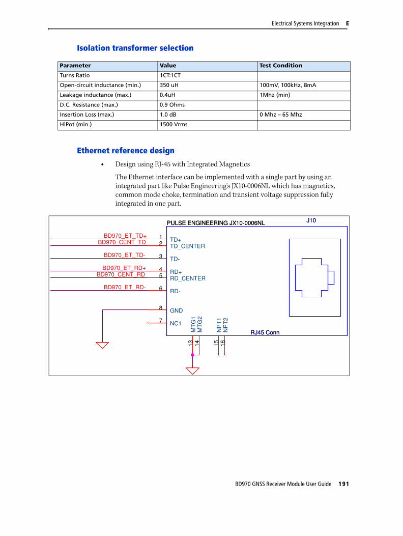
Electrical Systems Integration E
Isolation transformer selection
Ethernet reference design
• Design using RJ-45 with Integrated Magnetics
The Ethernet interface can be implemented with a single part by using an integrated part like Pulse Engineering's JX10-0006NL which has magnetics, common mode choke, termination and transient voltage suppression fully integrated in one part.
Parameter Value Test Condition
Turns Ratio 1CT:1CT
Open-circuit inductance (min.) 350 uH 100mV, 100kHz, 8mA
Leakage inductance (max.) 0.4uH 1Mhz (min)
D.C. Resistance (max.) 0.9 Ohms
Insertion Loss (max.) 1.0 dB 0 Mhz – 65 Mhz
HiPot (min.) 1500 Vrms
BD970_CENT_TDBD970_ET_TD+
BD970_CENT_RD
BD970_ET_RD-
BD970_ET_RD+
BD970_ET_TD-
TD_CENTER2
RD+4
RD-6
MT
G1
13
TD+1
TD-3
GND8
RD_CENTER5
NC17
MT
G2
14
NP
T1
15
NP
T2
16J10
RJ45 Conn
PULSE ENGINEERING JX10-0006NL J10
RJ45 Conn
PULSE ENGINEERING JX10-0006NL
BD970 GNSS Receiver Module User Guide 191

E Electrical Systems Integration
• Design using discrete components
For maximum flexibility, a system integrator may choose to implement the Ethernet using discrete parts. The design below shows an example of such a design. It includes the Ethernet magnetics, termination of unused lines as well as surge protection. The magnetics used is a Pulse Engineering HX1188. Surge protection is provided by a Semtech SLVU2.8-4. In order to meet electrical isolation requirements, it is recommended to use capacitors with a greater than 2 kV breakdown voltage.
RJ45_NC4RJ45_NC3
RJ45_NC2RJ45_NC1
BD975_ET_TD+
BD975_ET_RD-
BD975_ET_RD+
BD975_CENT_RD
BD975_CENT_TD
BD975_ET_TD+
BD975_ET_RD-BD975_ET_RD+
BD975_ET_TD-
ET_TD+
ET_TD-
ET_RD+
ET_RD-
ET_TD+
ET_TD-
ET_RD+
ET_RD-
BD975_ET_TD-
BD975_CENT_RD
ET_RD-
ET_TD-
ET_RD+
ET_TD+
BD975_CENT_TD
CHASSIS GROUND SIGNAL GROUND
TVS PROTECTION
Termination
R2349.9R2349.9
C31000pF 2kVC31000pF 2kV
R1649.9R1649.9
R1549.9R1549.9
R2549.9R2549.9
1
2
3
6
7
8
14
15
16
9
10
11
13
12
5N/C
T1PULSE ENGINEERING HX1188
N/C
T1PULSE ENGINEERING HX1188
L301Fer. BeadL301Fer. Bead
11
22
33
44
55
66
J2
Main Conn
J2
Main Conn
L300Fer. BeadL300Fer. Bead
C41000pF 2kV
C41000pF 2kV
TD+ 1
TD- 2
RD+ 3
RD- 6
100BT1 4100BT2 5
100BT3 7100BT4 8
NC19
NC210
J5RJ45 ConnJ5RJ45 Conn
R1349.9 R1349.9
R1149.9 R1149.9
R1749.9R1749.9
R2449.9R2449.9
4
1
6
7
8
2
3
5D7
SEMTECH SLVU2.8-4
D7
SEMTECH SLVU2.8-4C51000pF 2kVC51000pF 2kV
192 BD970 GNSS Receiver Module User Guide

Electrical Systems Integration E
Ethernet routing
The distance from J2, the BD970 Ethernet connector and the magnetics should be less than two inches. Minimize the distance from the RJ-45 and the magnetics to prevent conducted emissions issues. In this design, the chassis ground and signal ground are separated to improve radiated emissions: The integrator may choose to combine the ground.
For more detailed routing guidelines, see the following application note from the IC vendor.
Part reference Value
C3 1000pF 2kV
C4 1000pF 2kV
C5 1000pF 2kV
D7 SEMTECH SLVU2.8-4
J2 Main Conn
J5 RJ45 Conn
L300 Fer. Bead 300mA 1k@1mhz
L301 Fer. Bead 300mA 1k@1mhz
R11 49.9 0402 1%
R13 49.9 0402 1%
R15 49.9 0402 1%
R16 49.9 0402 1%
R17 49.9 0402 1%
R23 49.9 0402 1%
R24 49.9 0402 1%
R25 49.9 0402 1%
T1 PULSE ENGINEERING HX1188
BD970 GNSS Receiver Module User Guide 193
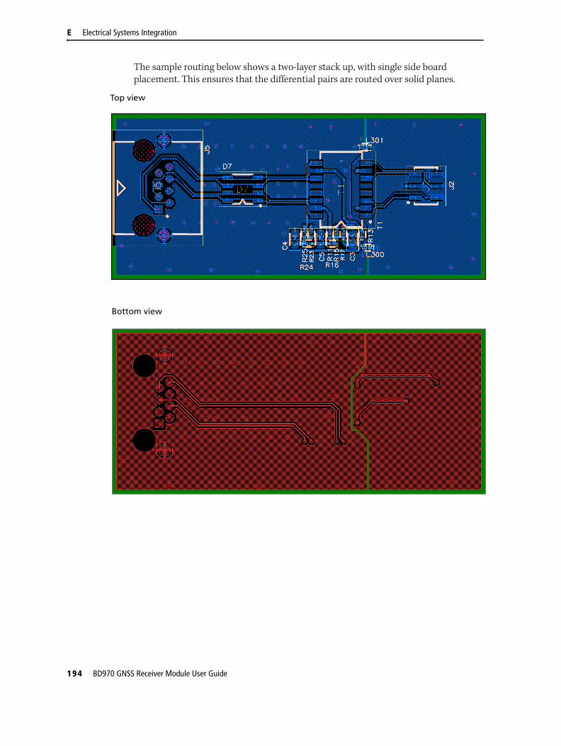
E Electrical Systems Integration
The sample routing below shows a two-layer stack up, with single side board placement. This ensures that the differential pairs are routed over solid planes.
Top view
Bottom view
194 BD970 GNSS Receiver Module User Guide

Glossary1PPS Pulse-per-second. Used in hardware timing. A pulse is generated in conjunction with a
time stamp. This defines the instant when the time stamp is applicable.
almanac A file that contains orbit information on all the satellites, clock corrections, and atmospheric delay parameters. The almanac is transmitted by a GPS satellite to a GPS receiver, where it facilitates rapid acquisition of GPS signals when you start collecting data, or when you have lost track of satellites and are trying to regain GPS signals.
The orbit information is a subset of the emphemeris / ephemerides data.
base station Also called reference station. A base station in construction, is a receiver placed at a known point on a job site that tracks the same satellites as an RTK rover, and provides a real-time differential correction message stream through radio to the rover, to obtain centimeter level positions on a continuous real-time basis. A base station can also be a part of a virtual reference station network, or a location at which GPS observations are collected over a period of time, for subsequent postprocessing to obtain the most accurate position for the location.
carrier A radio wave having at least one characteristic (such as frequency, amplitude, or phase) that can be varied from a known reference value by modulation.
carrier frequency The frequency of the unmodulated fundamental output of a radio transmitter. The GPS L1 carrier frequency is 1575.42 MHz.
carrier phase Is the cumulative phase count of the GPS or GLONASS carrier signal at a given time.
cellular modems A wireless adaptor that connects a laptop computer to a cellular phone system for data transfer. Cellular modems, which contain their own antennas, plug into a PC Card slot or into the USB port of the computer and are available for a variety of wireless data services such as GPRS.
CMR
CMR+
Compact Measurement Record. A real-time message format developed by Trimble for broadcasting corrections to other Trimble receivers. CMR is a more efficient alternative to RTCM.
covariance A statistical measure of the variance of two random variables that are observed or measured in the same mean time period. This measure is equal to the product of the deviations of corresponding values of the two variables from their respective means.
datum Also called geodetic datum. A mathematical model designed to best fit the geoid, defined by the relationship between an ellipsoid and, a point on the topographic surface, established as the origin of the datum. World geodetic datums are typically defined by the size and shape of an ellipsoid and the relationship between the center of the ellipsoid and the center of the earth.
Because the earth is not a perfect ellipsoid, any single datum will provide a better model in some locations than in others. Therefore, various datums have been established to suit particular regions.
For example, maps in Europe are often based on the European datum of 1950 (ED-50). Maps in the United States are often based on the North American datum of 1927 (NAD-27) or 1983 (NAD-83).
All GPS coordinates are based on the WGS-84 datum surface.
deep discharge Withdrawal of all electrical energy to the end-point voltage before the cell or battery is recharged.
DGPS See real-time differential GPS.
BD970 GNSS Receiver Module User Guide 197

Glossary
differential
correction
Differential correction is the process of correcting GPS data collected on a rover with data collected simultaneously at a base station. Because the base station is on a known location, any errors in data collected at the base station can be measured, and the necessary corrections applied to the rover data.
Differential correction can be done in real-time, or after the data has been collected.
differential GPS See real-time differential GPS.
DOP Dilution of Precision. A measure of the quality of GPS positions, based on the geometry of the satellites used to compute the positions. When satellites are widely spaced relative to each other, the DOP value is lower, and position accuracy is greater. When satellites are close together in the sky, the DOP is higher and GPS positions may contain a greater level of error.
PDOP (Position DOP) indicates the three-dimensional geometry of the satellites. Other DOP values include HDOP (Horizontal DOP) and VDOP (Vertical DOP), which indicate the accuracy of horizontal measurements (latitude and longitude) and vertical measurements respectively. PDOP is related to HDOP and VDOP as follows: PDOP2 = HDOP2 + VDOP2
dual-frequency GPS A type of receiver that uses both L1 and L2 signals from GPS satellites. A dual-frequency receiver can compute more precise position fixes over longer distances and under more adverse conditions because it compensates for ionospheric delays.
EGNOS European Geostationary Navigation Overlay Service. A satellite-based augmentation system (SBAS) that provides a free-to-air differential correction service for GPS. EGNOS is the European equivalent of WAAS, which is available in the United States.
elevation mask The angle below which the receiver will not track satellites. Normally set to 10 degrees to avoid interference problems caused by buildings and trees, atmospheric issues, and multipath errors.
ellipsoid An ellipsoid is the three-dimensional shape that is used as the basis for mathematically modeling the earth’s surface. The ellipsoid is defined by the lengths of the minor and major axes. The earth’s minor axis is the polar axis and the major axis is the equatorial axis.
emphemeris /
ephemerides
A list of predicted (accurate) positions or locations of satellites as a function of time. A set of numerical parameters that can be used to determine a satellite’s position. Available as broadcast ephemeris or as postprocessed precise ephemeris.
epoch The measurement interval of a GPS receiver. The epoch varies according to the measurement type: for real-time measurement it is set at one second; for postprocessed measurement it can be set to a rate of between one second and one minute. For example, if data is measured every 15 seconds, loading data using 30-second epochs means loading every alternate measurement.
feature A feature is a physical object or event that has a location in the real world, which you want to collect position and/or descriptive information (attributes) about. Features can be classified as surface or non-surface features, and again as points, lines/breaklines, or boundaries/areas.
firmware The program inside the receiver that controls receiver operations and hardware.
GLONASS Global Orbiting Navigation Satellite System. GLONASS is a Soviet space-based navigation system comparable to the American GPS system. The operational system consists of 21 operational and 3 non-operational satellites in 3 orbit planes.
GNSS Global Navigation Satellite System.
198 BD970 GNSS Receiver Module User Guide
Glossary
GSOF General Serial Output Format. A Trimble proprietary message format.
HDOP Horizontal Dilution of Precision. HDOP is a DOP value that indicates the accuracy of horizontal measurements. Other DOP values include VDOP (vertical DOP) and PDOP (Position DOP).
Using a maximum HDOP is ideal for situations where vertical precision is not particularly important, and your position yield would be decreased by the vertical component of the PDOP ( for example, if you are collecting data under canopy).
L1 The primary L-band carrier used by GPS and GLONASS satellites to transmit satellite data.
L2 The secondary L-band carrier used by GPS and GLONASS satellites to transmit satellite data.
L2C A modernized code that allows significantly better ability to track the L2 frequency.
L5 The third L-band carrier used by GPS satellites to transmit satellite data. L5 will provide a higher power level than the other carriers. As a result, acquiring and tracking weak signals will be easier.
Moving Base Moving Base is an RTK positioning technique in which both reference and rover receivers are mobile. Corrections are sent from a “base” receiver to a “rover” receiver and the resultant baseline (vector) has centimeter-level accuracy.
MSAS MTSAT Satellite-Based Augmentation System. A satellite-based augmentation system (SBAS) that provides a free-to-air differential correction service for GPS. MSAS is the Japanese equivalent of WAAS, which is available in the United States.
multipath Interference, similar to ghosts on an analog television screen, that occurs when GPS signals arrive at an antenna having traversed different paths. The signal traversing the longer path yields a larger pseudorange estimate and increases the error. Multiple paths can arise from reflections off the ground or off structures near the antenna.
NMEA National Marine Electronics Association. NMEA 0183 defines the standard for interfacing marine electronic navigational devices. This standard defines a number of 'strings' referred to as NMEA strings that contain navigational details such as positions. Most Trimble GPS receivers can output positions as NMEA strings.
PDOP Position Dilution of Precision. PDOP is a DOP value that indicates the accuracy of three-dimensional measurements. Other DOP values include VDOP (vertical DOP) and HDOP (Horizontal Dilution of Precision).
Using a maximum PDOP value is ideal for situations where both vertical and horizontal precision are important.
real-time differential
GPS
Also known as real-time differential correction or DGPS. Real-time differential GPS is the process of correcting GPS data as you collect it. Corrections are calculated at a base station and then sent to the receiver through a radio link. As the rover receives the position it applies the corrections to give you a very accurate position in the field.
Most real-time differential correction methods apply corrections to code phase positions.
While DGPS is a generic term, its common interpretation is that it entails the use of single-frequency code phase data sent from a GPS base station to a rover GPS receiver to provide sub-meter position accuracy. The rover receiver can be at a long range (greater than 100 kms (62 miles)) from the base station.
rover A rover is any mobile GPS receiver that is used to collect or update data in the field, typically at an unknown location.
BD970 GNSS Receiver Module User Guide 199

Glossary
RTCM Radio Technical Commission for Maritime Services. A commission established to define a differential data link for the real-time differential correction of roving GPS receivers. There are three versions of RTCM correction messages. All Trimble GPS receivers use Version 2 protocol for single-frequency DGPS type corrections. Carrier phase corrections are available on Version 2, or on the newer Version 3 RTCM protocol, which is available on certain Trimble dual-frequency receivers. The Version 3 RTCM protocol is more compact but is not as widely supported as Version 2.
RTK real-time kinematic. A real-time differential GPS method that uses carrier phase measurements for greater accuracy.
SBAS Satellite-Based Augmentation System. SBAS is based on differential GPS, but applies to wide area (WAAS/EGNOS and MSAS) networks of reference stations. Corrections and additional information are broadcast via geostationary satellites.
signal-to-noise ratio SNR. The signal strength of a satellite is a measure of the information content of the signal, relative to the signal’s noise. The typical SNR of a satellite at 30° elevation is between 47 and 50 dBHz.
skyplot The satellite skyplot confirms reception of a differentially corrected GPS signal and displays the number of satellites tracked by the GPS receiver, as well as their relative positions.
SNR See signal-to-noise ratio.
triple frequency GPS A type of receiver that uses three carrier phase measurements (L1, L2, and L5).
UTC Universal Time Coordinated. A time standard based on local solar mean time at the Greenwich meridian.
WAAS Wide Area Augmentation System. WAAS was established by the Federal Aviation Administration (FAA) for flight and approach navigation for civil aviation. WAAS improves the accuracy and availability of the basic GPS signals over its coverage area, which includes the continental United States and outlying parts of Canada and Mexico.
The WAAS system provides correction data for visible satellites. Corrections are computed from ground station observations and then uploaded to two geostationary satellites. This data is then broadcast on the L1 frequency, and is tracked using a channel on the GPS receiver, exactly like a GPS satellite.
Use WAAS when other correction sources are unavailable, to obtain greater accuracy than autonomous positions. For more information on WAAS, refer to the FAA website at http://gps.faa.gov.
The EGNOS service is the European equivalent and MSAS is the Japanese equivalent of WAAS.
WGS-84 World Geodetic System 1984. Since January 1987, WGS-84 has superseded WGS-72 as the datum used by GPS.
The WGS-84 datum is based on the ellipsoid of the same name.
200 BD970 GNSS Receiver Module User Guide


www.trimble.com
AMERICAS & ASIA-PACIFICTRIMBLE NAVIGATION LIMITEDIntegrated Technologies510 DeGuigne DriveSunnyvale, CA 94085USA+1-408-481-8090 Phone+1-408-481-8984 Fax
EUROPE & MIDDLE EAST TRIMBLE NAVIGATION LIMITEDIntegrated TechnologiesHAL Trade CenterBevelandseweg 1501703 AX HeerhugowaardNETHERLANDS+31-725-724-408 Phone+31-725-348-288 Fax
RUSSIATRIMBLE NAVIGATION LIMITEDIntegrated TechnologiesTel: +7-495-5041081RUSSIAEmail: [email protected]
CHINATRIMBLE NAVIGATION LIMITEDIntegrated Technologies311 Fute (M) Road, 3/FWai Gaoqiao Free Trade ZonePudong, Shanghai 200131CHINAEmail: [email protected]