trimmer potentiometers - electrical, computer &...
TRANSCRIPT

Cat.No.R50E-16
Trimmer Potentiometers
• This PDF catalog is downloaded from the website of Murata Manufacturing co., ltd. Therefore, it’s specifications are subject to change or our products in it may be discontinued without advance notice. Please check with our sales representatives or product engineers before ordering.
• This PDF catalog has only typical specifications because there is no space for detailed specifications. Therefore, please approve our product specifications or transact the approval sheet for product specifications before ordering.
!Note R50E.pdf08.8.26

for EU RoHS Compliant • All the products in this catalog comply with EU RoHS. • EU RoHS is "the European Directive 2002/95/EC on the Restriction of the Use
of Certain Hazardous Substances in Electrical and Electronic Equipment". • For more details, please refer to our website 'Murata's Approach for EU RoHS'
(http://www.murata.com/info/rohs.html).
!Note • Please read rating and !CAUTION (for storage, operating, rating, soldering, mounting and handling) in this catalog to prevent smoking and/or burning, etc.• This catalog has only typical specifications because there is no space for detailed specifications. Therefore, please approve our product specifications or transact the approval sheet for product specifications before ordering.
• This PDF catalog is downloaded from the website of Murata Manufacturing co., ltd. Therefore, it’s specifications are subject to change or our products in it may be discontinued without advance notice. Please check with our sales representatives or product engineers before ordering.
• This PDF catalog has only typical specifications because there is no space for detailed specifications. Therefore, please approve our product specifications or transact the approval sheet for product specifications before ordering.
!Note R50E.pdf08.8.26
CONTENTS
!Note • Please read rating and !CAUTION (for storage, operating, rating, soldering, mounting and handling) in this catalog to prevent smoking and/or burning, etc.• This catalog has only typical specifications because there is no space for detailed specifications. Therefore, please approve our product specifications or transact the approval sheet for product specifications before ordering.
Recycled Paper
1
2
3
4
5
6
7
8
Part Numbering 2
Selection Guide of Trimmer Potentiometers 3
SMD Open Type 2mm Size PVZ2/PVA2 Series 4
PVZ2/PVA2 Series Notice 8
SMD Open Type 3mm Size PVZ3 Series 10
PVZ3 Series Notice 13
SMD Sealed Type 2mm Size PVF2 Series 15
PVF2 Series Notice 16
SMD Sealed Type 3mm Size PVG3 Series 18
PVG3 Series Notice 21
SMD Sealed Type 4mm Size PVM4 Series 23
PVM4 Series Notice 25
SMD Sealed Type Multi-turn PVG5 Series 28
PVG5 Series Notice 30
Lead Sealed Type Single-turn PV32 Series 32
PV32 Series Notice 35
Lead Sealed Type Multi-turn PV12/PV37/PV36 Series 37
PV12/PV37/PV36 Series Notice 46
SMD Open Type (PVZ2/A2/Z3)/SMD Sealed Type (PVM4A_C01 Series) Specifications and Test Methods 48
SMD Sealed Type (PVF2/G3/M4A_D01/G5)/Lead Sealed Type (PV32/12/37/36) Specifications and Test Methods 49
Packaging 52
Recommended Adjustment Tools/Qualified Standards 56
1
2
3
4
5
6
7
8
• The RoHS compliance means that we judge from EU Directive 2002/95/EC the products do not contain lead, cadmium, mercury, hexavalent chromium, PBB and PBDE, except exemptions stated in EU Directive 2002/95/EC annex and impurities existing in the natural world.
• This statement does not insure the compliance of any of the listed parts with any laws or legal imperatives developed by any EU members individually with regards to the RoHS Directive.
• This PDF catalog is downloaded from the website of Murata Manufacturing co., ltd. Therefore, it’s specifications are subject to change or our products in it may be discontinued without advance notice. Please check with our sales representatives or product engineers before ordering.
• This PDF catalog has only typical specifications because there is no space for detailed specifications. Therefore, please approve our product specifications or transact the approval sheet for product specifications before ordering.
!Note R50E.pdf08.8.26

!Note • Please read rating and !CAUTION (for storage, operating, rating, soldering, mounting and handling) in this catalog to prevent smoking and/or burning, etc.• This catalog has only typical specifications because there is no space for detailed specifications. Therefore, please approve our product specifications or transact the approval sheet for product specifications before ordering.
2
o Part Numbering
qProduct ID
Trimmer Potentiometers
PV Trimmer Potentiometers
Product ID
(Part Number)
wSeries
eAdjustment Direction /Lead Type
Code Series CodeAdjustment Direction/
Lead Type
Z2SMD Open 2mm Size
Carbon Resistive Element
A2 SMD Open 2mm Size
A
R
Top
A Top
Rear
Z3
G3
F2
M4
G5
SMD Open 3mm SizeCarbon Resistive Element
SMD Sealed 4mm Size
32Lead Sealed 6mm Round
Single-turn
12Lead Sealed 7mm Round
4-turns
SMD Sealed 5mm Square11-turns
SMD Sealed 3mm Size
SMD Sealed 2mm Size
A
A
A
A
A
H
H
P
R
N
T
S
H
P
T
S
G
K
Top
G Top
Top
Top
Top
Side
Top, Triangle
Top, Triangle
Top, Inline
Side, Triangle
Side, Triangle
Side, Triangle
Top, Triangle
Top, Triangle
Side, Triangle
Side, Triangle
Top, J-hook
Top, Gull-wing
Rear
K Rear
36
37
Lead Sealed 10mm Square25-turns
Lead Sealed 6mm Square12-turns
W
Y
P
X
Z
W
Y
P
X
Z
Top, Inline
Top, Triangle
Side, Triangle
Side, Inline
Side, Triangle
Top, Triangle
Top, Inline
Side, Triangle
Side, Triangle
Side, Inline
rTotal Resistance
Expressed by three figures. The unit is ohm. The first and second figures are significant digits, and the third figure expresses the number of zeros which follow the two figures.
100
102
104
Ex.)
10Ω
1000Ω
100000Ω (=100kΩ)
Code Total Resistance
y
R00
e
A
t
C01
r
103PV
q w
Z3
tIndividual Specification
Series Code Individual Specification Code
Standard Type
Standard Type (High-heat Resistance Type/Ultra-thin Type)
PVA2
PVZ2
A01
C04
Standard Type (High-heat Resistance Type/Top Adjustment)
High Characteristic Carbon Type (only PVZ3G)
High-heat Resistance Type (for Rear Adjustment)
PVZ3
C01
F01
E01
Standard Type
High-liability TypePVM4
C01
D01
Standard Type (Resistance Change Characteristics: Linear)PVF2 A11
Standard TypePV32/PV12
PVG5
A01
Standard Type
Radial Taping
Standard Type
PV36/PV37C01
C31
C03
Standard TypeC01PVG3/
PV36/PV37
yPackaging
Ammo Pack
Bulk
Magazine
Reel
Code Packaging
A00
B00
M00*
R00
* M12 for PV36P Type and M15 for PV36W/Y/X/Z Type.
• This PDF catalog is downloaded from the website of Murata Manufacturing co., ltd. Therefore, it’s specifications are subject to change or our products in it may be discontinued without advance notice. Please check with our sales representatives or product engineers before ordering.
• This PDF catalog has only typical specifications because there is no space for detailed specifications. Therefore, please approve our product specifications or transact the approval sheet for product specifications before ordering.
!Note R50E.pdf08.8.26
!Note • Please read rating and !CAUTION (for storage, operating, rating, soldering, mounting and handling) in this catalog to prevent smoking and/or burning, etc.• This catalog has only typical specifications because there is no space for detailed specifications. Therefore, please approve our product specifications or transact the approval sheet for product specifications before ordering.
3
Selection Guide of Trimmer Potentiometers
• This PDF catalog is downloaded from the website of Murata Manufacturing co., ltd. Therefore, it’s specifications are subject to change or our products in it may be discontinued without advance notice. Please check with our sales representatives or product engineers before ordering.
• This PDF catalog has only typical specifications because there is no space for detailed specifications. Therefore, please approve our product specifications or transact the approval sheet for product specifications before ordering.
!Note R50E.pdf08.8.26
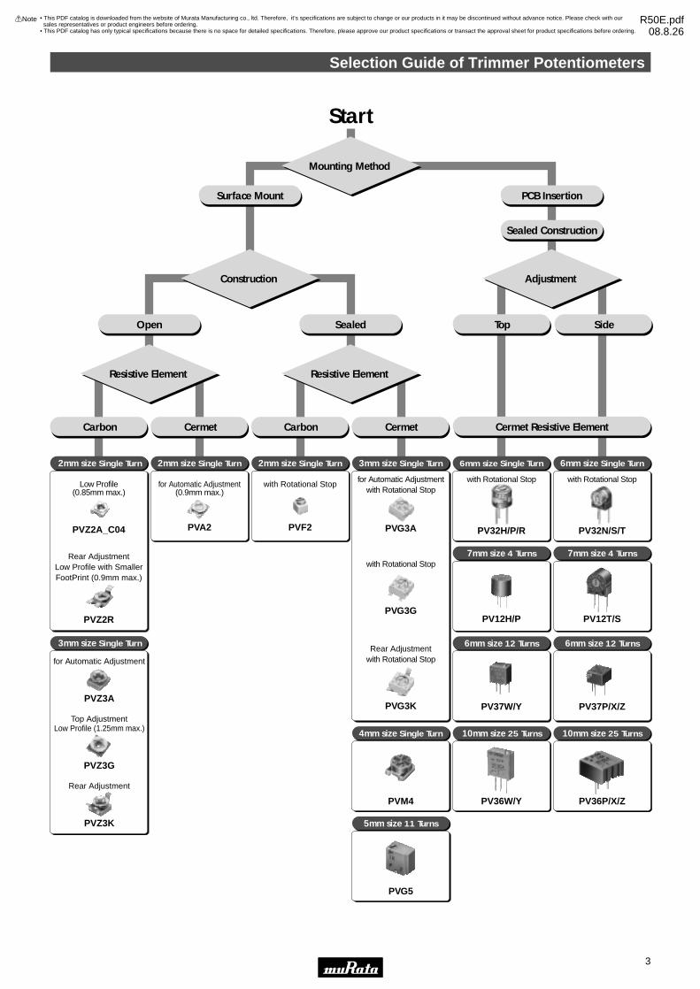
Start
Mounting Method
Construction Adjustment
2mm size Single Turn
Surface Mount PCB Insertion
Sealed Construction
Top Side
Resistive Element Resistive Element
Cermet Resistive Element
SealedOpen
2mm size Single Turn
3mm size Single Turn
3mm size Single Turn
4mm size Single Turn
5mm size 11 Turns
6mm size Single Turn
7mm size 4 Turns
6mm size 12 Turns
6mm size Single Turn
7mm size 4 Turns
6mm size 12 Turns
10mm size 25 Turns 10mm size 25 Turns
2mm size Single Turn
Carbon Cermet Carbon Cermet
PVM4
PVG5
PV12H/P
PV37W/Y
PV12T/S
PV37P/X/Z
PV36W/Y PV36P/X/Z
Low Profile (0.85mm max.)
PVZ2A_C04
Rear AdjustmentLow Profile with Smaller FootPrint (0.9mm max.)
PVZ2R
with Rotational Stop
PVF2
for Automatic Adjustment(0.9mm max.)
PVA2
for Automatic Adjustmentwith Rotational Stop
PVG3A
with Rotational Stop
PVG3G
Rear Adjustmentwith Rotational Stop
PVG3K
for Automatic Adjustment
PVZ3A
Top AdjustmentLow Profile (1.25mm max.)
PVZ3G
Rear Adjustment
PVZ3K
with Rotational Stop
PV32H/P/R
with Rotational Stop
PV32N/S/T

4
1
!Note • Please read rating and !CAUTION (for storage, operating, rating, soldering, mounting and handling) in this catalog to prevent smoking and/or burning, etc.• This catalog has only typical specifications because there is no space for detailed specifications. Therefore, please approve our product specifications or transact the approval sheet for product specifications before ordering.
Trimmer PotentiometersSMD Open Type 2mm Size PVZ2/PVA2 Series
PVZ2 Series2.1 0.8±0.05
0.5
0.4
0.45
±0.1
0.8
2.4 Dia.
1.3
2.2
2.7±
0.3
#2
0.7#1 #3
∗1
∗1 Driver Plate Rotation Area:Please do not place any componentsmore than 0.5mm in height within this area.
0.55 0.55
0.5
0.541
Soldering Part
(Tolerance: ±0.2)in mm
#2
#1 #3CLOCKWISE
PVZ2A
( Tolerance : ±0.2)in mm
#2
#1 #3CLOCKWISE
2.1
2.2
4.8
0.6 0.650.65
(0.6
)(0
.6)
0.80.8
+0.10-0.15
1.3
0.45
±0.1
0Soldering Part
#2
#1 #3
2.4 Dia.
∗1: Driver Plate Rotation Area
*1
PVZ2R
Part NumberPower Rating
(W)Soldering Method
Number of Turns(Effective Rotation Angle)
Total Resistance ValueTCR
(ppm/°C)
PVZ2p471C04 0.05(50°C) Reflow/Soldering Iron 1(240°±10°) 470ohm ±30% ±500
PVZ2p102C04 0.05(50°C) Reflow/Soldering Iron 1(240°±10°) 1k ohm ±30% ±500
PVZ2p222C04 0.05(50°C) Reflow/Soldering Iron 1(240°±10°) 2.2k ohm ±30% ±500
PVZ2p472C04 0.05(50°C) Reflow/Soldering Iron 1(240°±10°) 4.7k ohm ±30% ±500
PVZ2p103C04 0.05(50°C) Reflow/Soldering Iron 1(240°±10°) 10k ohm ±30% ±500
PVZ2p223C04 0.05(50°C) Reflow/Soldering Iron 1(240°±10°) 22k ohm ±30% ±500
PVZ2p473C04 0.05(50°C) Reflow/Soldering Iron 1(240°±10°) 47k ohm ±30% ±500
PVZ2p104C04 0.05(50°C) Reflow/Soldering Iron 1(240°±10°) 100k ohm ±30% ±500
PVZ2p224C04 0.05(50°C) Reflow/Soldering Iron 1(240°±10°) 220k ohm ±30% ±500
PVZ2p474C04 0.05(50°C) Reflow/Soldering Iron 1(240°±10°) 470k ohm ±30% ±500
PVZ2p105C04 0.05(50°C) Reflow/Soldering Iron 1(240°±10°) 1M ohm ±30% ±500
*Available for other resistance value.
Operating Temperature Range: -25 to 85 °CThe blank column is filled with the code of adjustment direction and lead type A (top) or R (rear).
Features1. Ultra-small and thin external dimensions of 2.1(W)x2.7(L)x0.85 max. (T)mm. (Top adjustment type: PVZ2A_C04 Series)2. Ultra-small and thin external dimensions of 2.1(W)x4.8(L)x0.9 max. (T)mm. (Rear adjustment type: PVZ2R_C04 Series) Compact PCB design is possible by smaller adjustment hole (3.0mm dia.) due to short wing length (4.8mm).3. Au plated termination achieves a high density PCB mounting.4. Cross-shaped driver slot allows for in-process automatic adjustment and it provides superior adjustability.5. Two-piece parts construction achieves low cost and excellent quality.6. Special resin substrate allows high peak temperature for reflow soldering. (PVZ2_Cxx Series)
Applications1. Pick-up module 2. LCD3. Cellular-phone 4. PHS5. Pager 6. DVC7. Digital camera 8. Portable audio, etc.
• This PDF catalog is downloaded from the website of Murata Manufacturing co., ltd. Therefore, it’s specifications are subject to change or our products in it may be discontinued without advance notice. Please check with our sales representatives or product engineers before ordering.
• This PDF catalog has only typical specifications because there is no space for detailed specifications. Therefore, please approve our product specifications or transact the approval sheet for product specifications before ordering.
!Note R50E.pdf08.8.26
5
1
!Note • Please read rating and !CAUTION (for storage, operating, rating, soldering, mounting and handling) in this catalog to prevent smoking and/or burning, etc.• This catalog has only typical specifications because there is no space for detailed specifications. Therefore, please approve our product specifications or transact the approval sheet for product specifications before ordering.
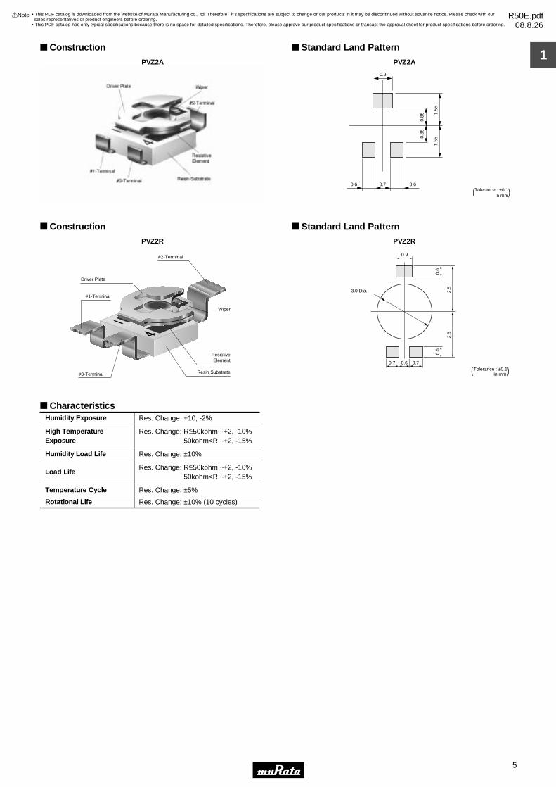
Construction
PVZ2A
Standard Land Pattern
PVZ2A
0.9
0.6 0.60.7
1.55
1.55
0.85
0.85
(Tolerance : ±0.1 in mm)
Construction
PVZ2R
Driver Plate
Wiper
Resistive Element
Resin Substrate
#2-Terminal
#3-Terminal
#1-Terminal
Standard Land Pattern
PVZ2R
3.0 Dia.
0.6
0.9
0.6
0.6
2.5
2.5
0.70.7
( Tolerance : ±0.1)in mm
CharacteristicsRes. Change: +10, -2%
Res. Change: R<50kohm···+2, -10% 50kohm<R···+2, -15%
Res. Change: ±10%
Res. Change: R<50kohm···+2, -10% 50kohm<R···+2, -15%
Res. Change: ±5%
Res. Change: ±10% (10 cycles)
Humidity Exposure
High TemperatureExposure
Humidity Load Life
Load Life
Temperature Cycle
Rotational Life
=
=
• This PDF catalog is downloaded from the website of Murata Manufacturing co., ltd. Therefore, it’s specifications are subject to change or our products in it may be discontinued without advance notice. Please check with our sales representatives or product engineers before ordering.
• This PDF catalog has only typical specifications because there is no space for detailed specifications. Therefore, please approve our product specifications or transact the approval sheet for product specifications before ordering.
!Note R50E.pdf08.8.26

6
1
!Note • Please read rating and !CAUTION (for storage, operating, rating, soldering, mounting and handling) in this catalog to prevent smoking and/or burning, etc.• This catalog has only typical specifications because there is no space for detailed specifications. Therefore, please approve our product specifications or transact the approval sheet for product specifications before ordering.
PVA2 Series
Features1. Ultra-small and thin external dimensions of 2.2(W)x2.75(L)x0.90 max.(T)mm.2. For the terminal attachment method of construction which uses neither solder nor adhesives, good solderability and terminal attachment intensity are realized.3. Because of multi-contact wiper structure, PVA2 has a stable characteristics (low noise).4. PVA2 series do not use a solder, flux and cleaning solvent, so they are environmentally friendly products.5. Heat resistance performance enables high temperature peak re-flow soldering.
Applications1. Thin-model optical pick-up module 2. LCD module3. Optical communication module 4. Small sensor module5. Digital camera6. Small telecommunicaions equipment, etc.
2.2
1.3
0.45
±0.1 0.8
0.8±0.1
0.4
0.5 0.6
0.5
2.75
1.3
0.9 0.6
0.75
#1
#2
#3
Resin
2.4 Dia
#2 (Wiper Contact)
#1 #3
CIRCUIT
CLOCKWISE
(Tolerance: ±0.2)in mm
Part NumberPower Rating
(W)Soldering Method
Number of Turns(Effective Rotation Angle)
Total Resistance ValueTCR
(ppm/°C)
PVA2A101A01 0.1(70°C) Reflow/Soldering Iron 1(260°±10°) 100ohm ±25% ±250
PVA2A221A01 0.1(70°C) Reflow/Soldering Iron 1(260°±10°) 220ohm ±25% ±250
PVA2A471A01 0.1(70°C) Reflow/Soldering Iron 1(260°±10°) 470ohm ±25% ±250
PVA2A102A01 0.1(70°C) Reflow/Soldering Iron 1(260°±10°) 1k ohm ±25% ±250
PVA2A222A01 0.1(70°C) Reflow/Soldering Iron 1(260°±10°) 2.2k ohm ±25% ±250
PVA2A472A01 0.1(70°C) Reflow/Soldering Iron 1(260°±10°) 4.7k ohm ±25% ±250
PVA2A103A01 0.1(70°C) Reflow/Soldering Iron 1(260°±10°) 10k ohm ±25% ±250
PVA2A223A01 0.1(70°C) Reflow/Soldering Iron 1(260°±10°) 22k ohm ±25% ±250
PVA2A473A01 0.1(70°C) Reflow/Soldering Iron 1(260°±10°) 47k ohm ±25% ±250
PVA2A104A01 0.1(70°C) Reflow/Soldering Iron 1(260°±10°) 100k ohm ±25% ±250
PVA2A224A01 0.1(70°C) Reflow/Soldering Iron 1(260°±10°) 220k ohm ±25% ±250
PVA2A474A01 0.1(70°C) Reflow/Soldering Iron 1(260°±10°) 470k ohm ±25% ±250
PVA2A105A01 0.1(70°C) Reflow/Soldering Iron 1(260°±10°) 1M ohm ±25% ±250
PVA2A225A01 0.1(70°C) Reflow/Soldering Iron 1(260°±10°) 2.2M ohm ±25% ±250
*Available for other resistance value.
Operating Temperature Range: -55 to 125 °C
• This PDF catalog is downloaded from the website of Murata Manufacturing co., ltd. Therefore, it’s specifications are subject to change or our products in it may be discontinued without advance notice. Please check with our sales representatives or product engineers before ordering.
• This PDF catalog has only typical specifications because there is no space for detailed specifications. Therefore, please approve our product specifications or transact the approval sheet for product specifications before ordering.
!Note R50E.pdf08.8.26

7
1
!Note • Please read rating and !CAUTION (for storage, operating, rating, soldering, mounting and handling) in this catalog to prevent smoking and/or burning, etc.• This catalog has only typical specifications because there is no space for detailed specifications. Therefore, please approve our product specifications or transact the approval sheet for product specifications before ordering.
Construction
Driver Plate
Resistive Element
Ceramic Substrate#3-Terminal
#1-Terminal
Wiper
#2-Terminal
Standard Land Pattern
( Tolerance : ±0.1 ) in mm
1.1
0.70
1.90
0.85
0.90
1.55
1.70
CharacteristicsRes. Change: ±3%
Res. Change: ±3%
Res. Change: ±3%
Res. Change: ±3%
Res. Change: ±3%
Res. Change: ±10% (10 cycles)
Humidity Exposure
High Temperature Exposure
Humidity Load Life
Load Life
Temperature Cycle
Rotational Life
• This PDF catalog is downloaded from the website of Murata Manufacturing co., ltd. Therefore, it’s specifications are subject to change or our products in it may be discontinued without advance notice. Please check with our sales representatives or product engineers before ordering.
• This PDF catalog has only typical specifications because there is no space for detailed specifications. Therefore, please approve our product specifications or transact the approval sheet for product specifications before ordering.
!Note R50E.pdf08.8.26
PVZ2/PVA2 Series Notice
8
1
!Note • Please read rating and !CAUTION (for storage, operating, rating, soldering, mounting and handling) in this catalog to prevent smoking and/or burning, etc.• This catalog has only typical specifications because there is no space for detailed specifications. Therefore, please approve our product specifications or transact the approval sheet for product specifications before ordering.
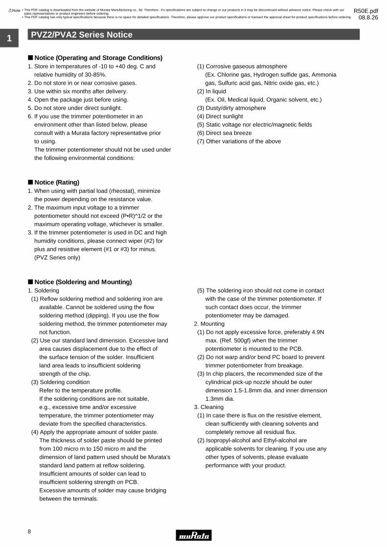
Notice (Operating and Storage Conditions)
Notice (Rating)1. When using with partial load (rheostat), minimize the power depending on the resistance value.2. The maximum input voltage to a trimmer potentiometer should not exceed (P•R)^1/2 or the maximum operating voltage, whichever is smaller.3. If the trimmer potentiometer is used in DC and high humidity conditions, please connect wiper (#2) for plus and resistive element (#1 or #3) for minus. (PVZ Series only)
Notice (Soldering and Mounting)
1. Store in temperatures of -10 to +40 deg. C and relative humidity of 30-85%.2. Do not store in or near corrosive gases.3. Use within six months after delivery. 4. Open the package just before using.5. Do not store under direct sunlight.6. If you use the trimmer potentiometer in an environment other than listed below, please consult with a Murata factory representative prior to using. The trimmer potentiometer should not be used under the following environmental conditions:
(1) Corrosive gaseous atmosphere (Ex. Chlorine gas, Hydrogen sulfide gas, Ammonia gas, Sulfuric acid gas, Nitric oxide gas, etc.) (2) In liquid (Ex. Oil, Medical liquid, Organic solvent, etc.) (3) Dusty/dirty atmosphere (4) Direct sunlight (5) Static voltage nor electric/magnetic fields (6) Direct sea breeze (7) Other variations of the above
1. Soldering (1) Reflow soldering method and soldering iron are available. Cannot be soldered using the flow soldering method (dipping). If you use the flow soldering method, the trimmer potentiometer may not function. (2) Use our standard land dimension. Excessive land area causes displacement due to the effect of the surface tension of the solder. Insufficient land area leads to insufficient soldering strength of the chip. (3) Soldering condition Refer to the temperature profile. If the soldering conditions are not suitable, e.g., excessive time and/or excessive temperature, the trimmer potentiometer may deviate from the specified characteristics. (4) Apply the appropriate amount of solder paste. The thickness of solder paste should be printed from 100 micro m to 150 micro m and the dimension of land pattern used should be Murata's standard land pattern at reflow soldering. Insufficient amounts of solder can lead to insufficient soldering strength on PCB. Excessive amounts of solder may cause bridging between the terminals.
(5) The soldering iron should not come in contact with the case of the trimmer potentiometer. If such contact does occur, the trimmer potentiometer may be damaged.2. Mounting (1) Do not apply excessive force, preferably 4.9N max. (Ref. 500gf) when the trimmer potentiometer is mounted to the PCB. (2) Do not warp and/or bend PC board to prevent trimmer potentiometer from breakage. (3) In chip placers, the recommended size of the cylindrical pick-up nozzle should be outer dimension 1.5-1.8mm dia. and inner dimension 1.3mm dia.3. Cleaning (1) In case there is flux on the resistive element, clean sufficiently with cleaning solvents and completely remove all residual flux. (2) Isopropyl-alcohol and Ethyl-alcohol are applicable solvents for cleaning. If you use any other types of solvents, please evaluate performance with your product.
• This PDF catalog is downloaded from the website of Murata Manufacturing co., ltd. Therefore, it’s specifications are subject to change or our products in it may be discontinued without advance notice. Please check with our sales representatives or product engineers before ordering.
• This PDF catalog has only typical specifications because there is no space for detailed specifications. Therefore, please approve our product specifications or transact the approval sheet for product specifications before ordering.
!Note R50E.pdf08.8.26

PVZ2/PVA2 Series Notice
9
1
!Note • Please read rating and !CAUTION (for storage, operating, rating, soldering, mounting and handling) in this catalog to prevent smoking and/or burning, etc.• This catalog has only typical specifications because there is no space for detailed specifications. Therefore, please approve our product specifications or transact the approval sheet for product specifications before ordering.
Soldering Profile
Tem
pera
ture
(°C
)
t3
t2
T3T2
T5
T4
T1
Time (s)t1
1. Soldering profile for Lead-free solder (96.5Sn/3.0Ag/0.5Cu)
Standard Profile
Pre-heating Heating Cycle ofReflow
Time°C
Series
PVA2
PVZ2****C**
Temp. (T1)
°C
Time (t1)
sec.
Temp. (T2)
°C
Time (t2)
sec.
Pre-heating Heating Cycle ofReflow
Time°C
Temp. (T1)
°C
Time (t1)
sec.
Temp. (T4)
°C
Time (t3)
sec.
Limit Profile
2
2
245±3
245±3
150 to 180
150 to 180
60 to 120
60 to 120
220
220
30 to 60
30 to 60
2
2
260 +5/-0
260
150 to 180
150 to 180
60 to 120
60 to 120
220
220
30 to 60
30 to 60
Limit Profile
Standard Profile
Standard Profile
Pre-heating Heating Cycle ofReflow
Time°C
Series
PVA2PVZ2****C**
Temp. (T1)
°C
Time (t1)
sec.
Temp. (T2)
°C
Time (t2)
sec.
1230150 60 to 120 183 30
Tem
pera
ture
(°C
)
time (s)
Standard Profile
t1
T1 t2
T3
T2
2. Soldering profile for Eutectic solder (63Sn/37Pb)
(Limit profile: refer to 1)
Standard Condition
Series
PVA2PVZ2****C**
Temperature of Soldering Iron Tip Soldering Time Soldering Iron Power Output
350±10 3 max. 30 max. 1
Cycle of Soldering Iron
°C sec. W Time
Reflow Soldering Profile
Soldering Iron
PeakTemperature
(T3)
PeakTemperature
(T5)
PeakTemperature
(T3)
Notice (Handling)1. Use suitable screwdrivers that fit comfortably in driver slot. We recommend the screwdriver below. * Recommended screwdriver for manual adjustment Murata P/N: KMDR1902. The screwdriver should be set in the products vertically, do not apply more than 4.9N (Ref. 500gf) of twist and stress after mounting onto PCB to prevent contact intermittence. If excessive force is applied, the trimmer potentiometer may not function.
3. Please use within the effective rotational angle. The trimmer potentiometer does not have a mechanical stop for over rotation. In cases out of effective rotational angle, the trimmer potentiometer may not function.4. When using a lock paint to fix slot position or cover the rotor, please evaluate performance with your product. Lock paint may cause corrosion or electrical contact problems.
Notice (Other)1. Please make sure that your product has been evaluated and confirmed against your specifications when our product is mounted to your product.
2. Murata cannot guarantee trimmer potentiometer integrity when used under conditions other than those specified in this document.
• This PDF catalog is downloaded from the website of Murata Manufacturing co., ltd. Therefore, it’s specifications are subject to change or our products in it may be discontinued without advance notice. Please check with our sales representatives or product engineers before ordering.
• This PDF catalog has only typical specifications because there is no space for detailed specifications. Therefore, please approve our product specifications or transact the approval sheet for product specifications before ordering.
!Note R50E.pdf08.8.26

10
2
!Note • Please read rating and !CAUTION (for storage, operating, rating, soldering, mounting and handling) in this catalog to prevent smoking and/or burning, etc.• This catalog has only typical specifications because there is no space for detailed specifications. Therefore, please approve our product specifications or transact the approval sheet for product specifications before ordering.
Trimmer PotentiometersSMD Open Type 3mm Size PVZ3 Series
PVZ3 Series
#2
#1 #3
CLOCKWISE
#1
#2
#3
3.1
1.0
0.75 1.0 0.75
2.4±
0.1
3.2
3.6
0.5±
0.1
1.15 Dia.
2.2 Dia.
3.0 Dia.
1.85±0.1
0.25±0.1 0.1 max.
0.7
0.7
(Tolerance: ±0.3)in mm
PVZ3A
3.1
3.1
0.8#2
#1 #30.55 0.55
1.15±0.10
1.2
3.6
0.4
0.6
0.55
R1.5
2.1±
0.1
0.5±
0.1
R0.75
#2 (Wiper Contact)
#1 #3CLOCKWISE
CIRCUIT
(Tolerance: ±0.3 in mm)
PVZ3G
#1#3
3.1 1.85±0.12.1
0.25±0.1
3.2
0.5±
0.1
5.4
4.4
2.4±
0.1
#2
0.85
1.1
0.9 0.85
1.15 Dia.
3.0 Dia.2.2 Dia.
Soldering Part
#2 (Wiper Contact)
#1 #3
CIRCUIT
CLOCKWISE
(Tolerance: ±0.3)in mm
PVZ3K
Part NumberPower Rating
(W)Soldering Method
Number of Turns(Effective Rotation Angle)
Total Resistance ValueTCR
(ppm/°C)
PVZ3p221C01 0.1(50°C) Reflow/Soldering Iron 1(230°±10°) 220ohm ±30% ±500
PVZ3p471C01 0.1(50°C) Reflow/Soldering Iron 1(230°±10°) 470ohm ±30% ±500
PVZ3p102C01 0.1(50°C) Reflow/Soldering Iron 1(230°±10°) 1k ohm ±30% ±500
PVZ3p222C01 0.1(50°C) Reflow/Soldering Iron 1(230°±10°) 2.2k ohm ±30% ±500
PVZ3p472C01 0.1(50°C) Reflow/Soldering Iron 1(230°±10°) 4.7k ohm ±30% ±500
PVZ3p103C01 0.1(50°C) Reflow/Soldering Iron 1(230°±10°) 10k ohm ±30% ±500
PVZ3p223C01 0.1(50°C) Reflow/Soldering Iron 1(230°±10°) 22k ohm ±30% ±500
PVZ3p473C01 0.1(50°C) Reflow/Soldering Iron 1(230°±10°) 47k ohm ±30% ±500
PVZ3p104C01 0.1(50°C) Reflow/Soldering Iron 1(230°±10°) 100k ohm ±30% ±500
PVZ3p224C01 0.1(50°C) Reflow/Soldering Iron 1(230°±10°) 220k ohm ±30% ±500
Continued on the following page.
Features1. Excellent solderability characteristics are achieved via special plating techniques on each termination.2. Specially designed substrate prevents wicking of flux onto the top of the part body.3. Funnel shaped adjustment slot allows for in-process automatic adjustment. (PVZ3A/PVZ3K Series) 4. High-heat resistance type is available (PVZ3A_C01/PVZ3G_C01/PVZ3K_E01).5. Enlarged bottom termination enhances soldering strength while reducing the necessary land area required promoting high-density PCB mounting (PVZ3A/PVZ3G Series).6. The standard position of driver plate is adjusted at the center normally, but another position is also available.7. This product meets PB-free standards.
Applications1. Optical pick up 2. Cordless telephones3. CD players 4. FDD5. Motor 6. CD-ROMs7. Car stereos 8. TFT-LCD TV sets9. Headphone stereos
• This PDF catalog is downloaded from the website of Murata Manufacturing co., ltd. Therefore, it’s specifications are subject to change or our products in it may be discontinued without advance notice. Please check with our sales representatives or product engineers before ordering.
• This PDF catalog has only typical specifications because there is no space for detailed specifications. Therefore, please approve our product specifications or transact the approval sheet for product specifications before ordering.
!Note R50E.pdf08.8.26

11
2
!Note • Please read rating and !CAUTION (for storage, operating, rating, soldering, mounting and handling) in this catalog to prevent smoking and/or burning, etc.• This catalog has only typical specifications because there is no space for detailed specifications. Therefore, please approve our product specifications or transact the approval sheet for product specifications before ordering.
Part NumberPower Rating
(W)Soldering Method
Number of Turns(Effective Rotation Angle)
Total Resistance ValueTCR
(ppm/°C)
Continued from the preceding page.
PVZ3p474C01 0.1(50°C) Reflow/Soldering Iron 1(230°±10°) 470k ohm ±30% ±500
PVZ3p105C01 0.1(50°C) Reflow/Soldering Iron 1(230°±10°) 1M ohm ±30% ±500
PVZ3p225C01 0.1(50°C) Reflow/Soldering Iron 1(230°±10°) 2.2M ohm ±30% ±500
PVZ3p221E01 0.1(50°C) Reflow/Soldering Iron 1(230°±10°) 220ohm ±30% ±500
PVZ3p471E01 0.1(50°C) Reflow/Soldering Iron 1(230°±10°) 470ohm ±30% ±500
PVZ3p102E01 0.1(50°C) Reflow/Soldering Iron 1(230°±10°) 1k ohm ±30% ±500
PVZ3p222E01 0.1(50°C) Reflow/Soldering Iron 1(230°±10°) 2.2k ohm ±30% ±500
PVZ3p472E01 0.1(50°C) Reflow/Soldering Iron 1(230°±10°) 4.7k ohm ±30% ±500
PVZ3p103E01 0.1(50°C) Reflow/Soldering Iron 1(230°±10°) 10k ohm ±30% ±500
PVZ3p223E01 0.1(50°C) Reflow/Soldering Iron 1(230°±10°) 22k ohm ±30% ±500
PVZ3p473E01 0.1(50°C) Reflow/Soldering Iron 1(230°±10°) 47k ohm ±30% ±500
PVZ3p104E01 0.1(50°C) Reflow/Soldering Iron 1(230°±10°) 100k ohm ±30% ±500
PVZ3p224E01 0.1(50°C) Reflow/Soldering Iron 1(230°±10°) 220k ohm ±30% ±500
PVZ3p474E01 0.1(50°C) Reflow/Soldering Iron 1(230°±10°) 470k ohm ±30% ±500
PVZ3p105E01 0.1(50°C) Reflow/Soldering Iron 1(230°±10°) 1M ohm ±30% ±500
PVZ3p225E01 0.1(50°C) Reflow/Soldering Iron 1(230°±10°) 2.2M ohm ±30% ±500
*Available for other resistance value.
Operating Temperature Range: -25 to 85 °CThe blank column is filled with the code of adjustment direction and lead type A (top adjustment), G (top adjustment and thin type),
K (rear adjustment).
A and G are only for C01.
K is only for E01.
Construction
PVZ3A
Construction
PVZ3G
Driver Plate Wiper
Resistive Element
Resin Substrate
#2-Terminal
#3-Terminal
#1-Terminal
Standard Land Pattern
PVZ3A/PVZ3G
1.1
0.9
1.9
1.9
0.9
1.0 0.7 1.0
Tolerance : ±0.1 ( in mm)
• This PDF catalog is downloaded from the website of Murata Manufacturing co., ltd. Therefore, it’s specifications are subject to change or our products in it may be discontinued without advance notice. Please check with our sales representatives or product engineers before ordering.
• This PDF catalog has only typical specifications because there is no space for detailed specifications. Therefore, please approve our product specifications or transact the approval sheet for product specifications before ordering.
!Note R50E.pdf08.8.26

12
2
!Note • Please read rating and !CAUTION (for storage, operating, rating, soldering, mounting and handling) in this catalog to prevent smoking and/or burning, etc.• This catalog has only typical specifications because there is no space for detailed specifications. Therefore, please approve our product specifications or transact the approval sheet for product specifications before ordering.
Construction
PVZ3KDriver Plate
WiperResistive Element
(Carbon)
Resin Substrate
#2-Terminal
#3-Terminal
#1-Terminal
Standard Land Pattern
PVZ3K1.5
1.0
4.0
1.0
0.5
3.0
3.0 Dia
Tolerance : ±0.1 ( in mm)
CharacteristicsRes. Change: +10, -2%
Res. Change: R<100kohm···+2, -10%100kohm<R···+2, -15%
Res. Change: ±10%
Res. Change: R<100kohm···+2, -10%100kohm<R···+2, -15%
Res. Change: ±5%
Res. Change: ±10% (10 cycles)
Humidity Exposure
High TemperatureExposure
Humidity Load Life
Load Life
Temperature Cycle
Rotational Life
=
=
• This PDF catalog is downloaded from the website of Murata Manufacturing co., ltd. Therefore, it’s specifications are subject to change or our products in it may be discontinued without advance notice. Please check with our sales representatives or product engineers before ordering.
• This PDF catalog has only typical specifications because there is no space for detailed specifications. Therefore, please approve our product specifications or transact the approval sheet for product specifications before ordering.
!Note R50E.pdf08.8.26
PVZ3 Series Notice
13
2
!Note • Please read rating and !CAUTION (for storage, operating, rating, soldering, mounting and handling) in this catalog to prevent smoking and/or burning, etc.• This catalog has only typical specifications because there is no space for detailed specifications. Therefore, please approve our product specifications or transact the approval sheet for product specifications before ordering.
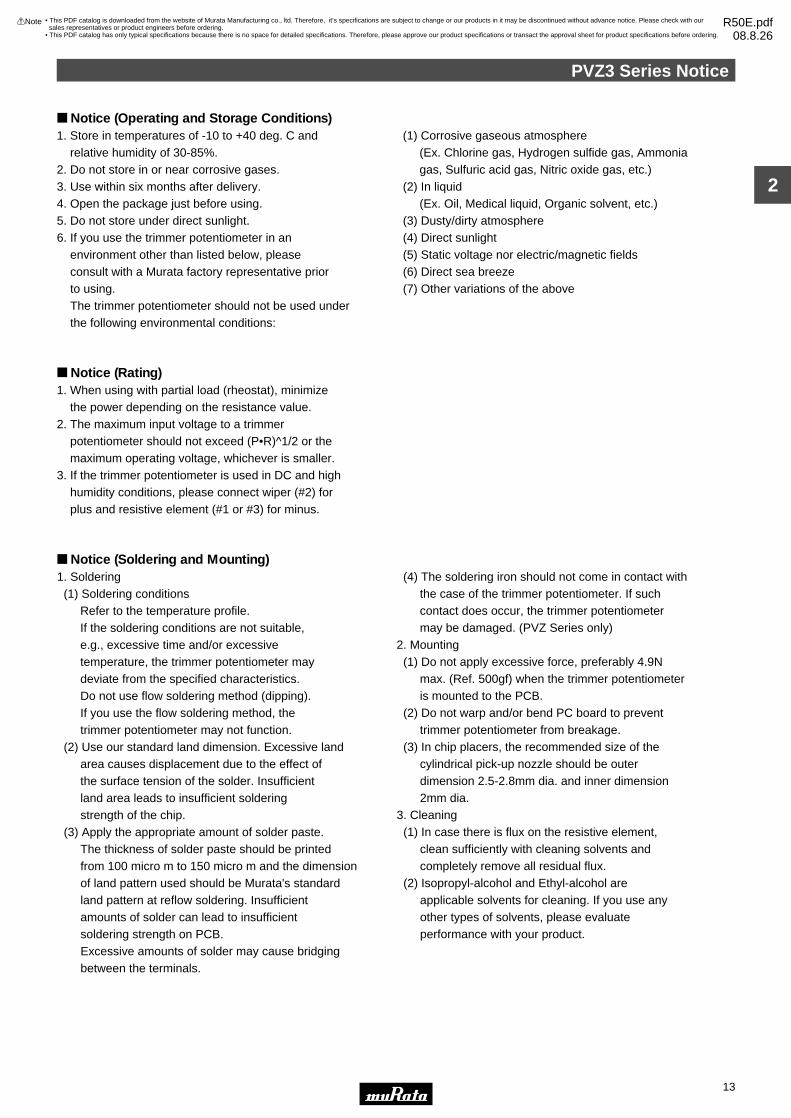
Notice (Operating and Storage Conditions)
Notice (Rating)1. When using with partial load (rheostat), minimize the power depending on the resistance value.2. The maximum input voltage to a trimmer potentiometer should not exceed (P•R)^1/2 or the maximum operating voltage, whichever is smaller.3. If the trimmer potentiometer is used in DC and high humidity conditions, please connect wiper (#2) for plus and resistive element (#1 or #3) for minus.
Notice (Soldering and Mounting)
1. Store in temperatures of -10 to +40 deg. C and relative humidity of 30-85%.2. Do not store in or near corrosive gases.3. Use within six months after delivery. 4. Open the package just before using.5. Do not store under direct sunlight.6. If you use the trimmer potentiometer in an environment other than listed below, please consult with a Murata factory representative prior to using. The trimmer potentiometer should not be used under the following environmental conditions:
(1) Corrosive gaseous atmosphere (Ex. Chlorine gas, Hydrogen sulfide gas, Ammonia gas, Sulfuric acid gas, Nitric oxide gas, etc.) (2) In liquid (Ex. Oil, Medical liquid, Organic solvent, etc.) (3) Dusty/dirty atmosphere (4) Direct sunlight (5) Static voltage nor electric/magnetic fields (6) Direct sea breeze (7) Other variations of the above
1. Soldering (1) Soldering conditions Refer to the temperature profile. If the soldering conditions are not suitable, e.g., excessive time and/or excessive temperature, the trimmer potentiometer may deviate from the specified characteristics. Do not use flow soldering method (dipping). If you use the flow soldering method, the trimmer potentiometer may not function. (2) Use our standard land dimension. Excessive land area causes displacement due to the effect of the surface tension of the solder. Insufficient land area leads to insufficient soldering strength of the chip. (3) Apply the appropriate amount of solder paste. The thickness of solder paste should be printed from 100 micro m to 150 micro m and the dimension of land pattern used should be Murata's standard land pattern at reflow soldering. Insufficient amounts of solder can lead to insufficient soldering strength on PCB. Excessive amounts of solder may cause bridging between the terminals.
(4) The soldering iron should not come in contact with the case of the trimmer potentiometer. If such contact does occur, the trimmer potentiometer may be damaged. (PVZ Series only)2. Mounting (1) Do not apply excessive force, preferably 4.9N max. (Ref. 500gf) when the trimmer potentiometer is mounted to the PCB. (2) Do not warp and/or bend PC board to prevent trimmer potentiometer from breakage. (3) In chip placers, the recommended size of the cylindrical pick-up nozzle should be outer dimension 2.5-2.8mm dia. and inner dimension 2mm dia.3. Cleaning (1) In case there is flux on the resistive element, clean sufficiently with cleaning solvents and completely remove all residual flux. (2) Isopropyl-alcohol and Ethyl-alcohol are applicable solvents for cleaning. If you use any other types of solvents, please evaluate performance with your product.
• This PDF catalog is downloaded from the website of Murata Manufacturing co., ltd. Therefore, it’s specifications are subject to change or our products in it may be discontinued without advance notice. Please check with our sales representatives or product engineers before ordering.
• This PDF catalog has only typical specifications because there is no space for detailed specifications. Therefore, please approve our product specifications or transact the approval sheet for product specifications before ordering.
!Note R50E.pdf08.8.26

PVZ3 Series Notice
14
2
!Note • Please read rating and !CAUTION (for storage, operating, rating, soldering, mounting and handling) in this catalog to prevent smoking and/or burning, etc.• This catalog has only typical specifications because there is no space for detailed specifications. Therefore, please approve our product specifications or transact the approval sheet for product specifications before ordering.
Soldering Profile
Tem
pera
ture
(°C
)
t3
t2
T3T2
T5
T4
T1
Time (s)t1
1. Soldering profile for Lead-free solder (96.5Sn/3.0Ag/0.5Cu)
Standard Profile
Pre-heating Heating Cycle ofReflow
Cycle ofReflow
Time°C
Series
PVZ3xxxxCxx
PVZ3GxxxFxx
PVZ3xxxxExx
Temp. (T1)
°C
Time (t1)
sec.
Temp. (T2)
°C
Time (t2)
sec.
Pre-heating Heating
Time°C
Temp. (T1)
°C
Time (t1)
sec.
Temp. (T4)
°C
Time (t3)
sec.
Limit Profile
2
2
2
245±3
245±3
245±3
150 to 180
150 to 180
150 to 180
60 to 120
60 to 120
60 to 120
220
220
220
30 to 60
30 to 60
30 to 60
2
2
2
260
260
260
150 to 180
150 to 180
150 to 180
60 to 120
60 to 120
60 to 120
220
220
220
30 to 60
30 to 60
30 to 60
Limit Profile
Standard Profile
Standard Profile
Pre-heating HeatingSeries
PVZ3xxxxCxxPVZ3GxxxFxxPVZ3xxxxExx
Temp. (T1)
°C
Time (t1)
sec.
Temp. (T2)
°C
Time (t2)
sec.
Tem
pera
ture
(°C
)
Time (s)
Standard Profile
t1
T1 t2
T3
T2
2. Soldering profile for Eutectic solder (63Sn/37Pb)
(Limit profile: refer to 1)
Standard Condition
Series
PVZ3xxxxCxxPVZ3GxxxFxxPVZ3xxxxExx
Temperature of Soldering Iron Tip Soldering Time Soldering Iron Power Output
350±10 3 max. 30 max. 1
Cycle of Solder Iron
°C sec. W Time
Reflow Soldering Profile
PeakTemperature
(T3)
PeakTemperature
(T5)
Cycle ofReflow
Time°C
1230 max.150 60 to 120 183 30
PeakTemperature
(T3)
Soldering Iron
Notice (Handling)
Notice (Other)1. Please make sure that your product has been evaluated and confirmed against your specifications when our product is mounted to your product.
2. Murata cannot guarantee trimmer potentiometer integrity when used under conditions other than those specified in this document.
1. Use suitable screwdrivers that fit comfortably in driver slot. We recommend the screwdrivers below. * Recommended screwdriver for manual adjustment >VESSEL MFG.: NO.9000+1.7x30 (Murata P/N: KMDR080) * Recommended screwdriver for automatic adjustment >TORAY MFG.: JB-2225 (Murata P/N: KMBT070) 2. Don't apply more than 4.9N (Ref.; 500gf) of twist and stress after mounting onto PCB to prevent contact intermittence. If excessive force is applied, the trimmer potentiometer may not function.
3. Please use within the effective rotational angle. Do not have a mechanical stop for over rotation. In cases out of effective rotational angle, the trimmer potentiometer may not function.4. When using a lock paint to fix slot position or cover the rotor, please evaluate performance by your product. Lock paint may cause corrosion or electrical contact problems.
• This PDF catalog is downloaded from the website of Murata Manufacturing co., ltd. Therefore, it’s specifications are subject to change or our products in it may be discontinued without advance notice. Please check with our sales representatives or product engineers before ordering.
• This PDF catalog has only typical specifications because there is no space for detailed specifications. Therefore, please approve our product specifications or transact the approval sheet for product specifications before ordering.
!Note R50E.pdf08.8.26

15
3
!Note • Please read rating and !CAUTION (for storage, operating, rating, soldering, mounting and handling) in this catalog to prevent smoking and/or burning, etc.• This catalog has only typical specifications because there is no space for detailed specifications. Therefore, please approve our product specifications or transact the approval sheet for product specifications before ordering.
Trimmer PotentiometersSMD Sealed Type 2mm Size PVF2 Series
Features1. Ultra-compact size of "2x2x2.3mm" 2. A sealed structure prevents liquids (water, cleaning liquid, sweat, etc.) from entering.3. A rotation service life of 100 cycles is guaranteed.4. Can be automatically mounted using a chip placer, as well as mounted using reflow soldering.
Applications1. Hearing aids2. Ultra-compact sensors or the like3. Applications requiring ultra-compactness, and a sealed structure
Marking 2.00#2
#1 #3
1.6 Dia.
2.00
0.30
2.15
max
.
2.30±0.150.50
0.30 0.70
±0.1
5
0.70
±0.1
5
0.30±0.15
0.50
0.30
0.50
#2 (Wiper)
#1 #3
Clockwise
CIRCUIT
(Tolerance: ±0.10 in mm)
Part NumberPower Rating
(W)Soldering Method
Number of Turns(Effective Rotation Angle)
Total Resistance ValueTCR
(ppm/°C)
PVF2A501A11 0.001(50°C) Reflow/Soldering Iron 1(210°±10°) 500ohm ±30% ±500
PVF2A102A11 0.001(50°C) Reflow/Soldering Iron 1(210°±10°) 1k ohm ±30% ±500
PVF2A202A11 0.001(50°C) Reflow/Soldering Iron 1(210°±10°) 2k ohm ±30% ±500
PVF2A502A11 0.001(50°C) Reflow/Soldering Iron 1(210°±10°) 5k ohm ±30% ±500
PVF2A103A11 0.001(50°C) Reflow/Soldering Iron 1(210°±10°) 10k ohm ±30% ±500
PVF2A203A11 0.001(50°C) Reflow/Soldering Iron 1(210°±10°) 20k ohm ±30% ±500
PVF2A503A11 0.001(50°C) Reflow/Soldering Iron 1(210°±10°) 50k ohm ±30% ±500
PVF2A104A11 0.001(50°C) Reflow/Soldering Iron 1(210°±10°) 100k ohm ±30% ±500
PVF2A204A11 0.001(50°C) Reflow/Soldering Iron 1(210°±10°) 200k ohm ±30% ±500
PVF2A504A11 0.001(50°C) Reflow/Soldering Iron 1(210°±10°) 500k ohm ±30% ±500
PVF2A105A11 0.001(50°C) Reflow/Soldering Iron 1(210°±10°) 1M ohm ±30% ±500
Operating Temperature Range: -25 to 60 °C
Construction
O-ring
Rotor
Terminal
Shaft
Case
SubstrateWiper
Resistive Element
Standard Land Pattern0.60
0.90
0.90
2.20
0.60 0.60
0.40
Tolerance : ±0.10 ( in mm )
Characteristics
∆TR : Total Resistance Change
∆V.S.S.: Voltage Setting Stability
Temperature Cycle
Humidity
Vibration
Shock (100G)
Temperature Load Life
Low Temperature Exposure
Rotational Life
∆TR : ±5%
∆TR : ±15, -2%
∆V.S.S. : ±5%
∆V.S.S. : ±5%
∆TR : +2, -10%
∆TR : ±3%
∆TR : ±10% (100 cycles)
• This PDF catalog is downloaded from the website of Murata Manufacturing co., ltd. Therefore, it’s specifications are subject to change or our products in it may be discontinued without advance notice. Please check with our sales representatives or product engineers before ordering.
• This PDF catalog has only typical specifications because there is no space for detailed specifications. Therefore, please approve our product specifications or transact the approval sheet for product specifications before ordering.
!Note R50E.pdf08.8.26

PVF2 Series Notice
16
3
!Note • Please read rating and !CAUTION (for storage, operating, rating, soldering, mounting and handling) in this catalog to prevent smoking and/or burning, etc.• This catalog has only typical specifications because there is no space for detailed specifications. Therefore, please approve our product specifications or transact the approval sheet for product specifications before ordering.
Notice (Operating and Storage Conditions)
Notice (Rating)1. When using with partial load (rheostat), minimize the power depending on the resistance value.2. The maximum input voltage to a trimmer potentiometer should not exceed (P•R)^1/2 or the maximum operating voltage, whichever is smaller.3. If the trimmer potentiometer is used in DC and high humidity conditions, please connect wiper (#2) for plus and resistive element (#1 or #3) for minus.
Notice (Soldering and Mounting)
1. Store in temperatures of -10 to +40 deg. C and relative humidity of 30-85%.2. Do not store in or near corrosive gases.3. Use within six months after delivery. 4. Open the package just before using.5. Do not store under direct sunlight.6. If you use the trimmer potentiometer in an environment other than listed below, please consult with a Murata factory representative prior to using. The trimmer potentiometer should not be used under the following environmental conditions:
(1) Corrosive gaseous atmosphere (Ex. Chlorine gas, Hydrogen sulfide gas, Ammonia gas, Sulfuric acid gas, Nitric oxide gas, etc.) (2) In liquid (Ex. Oil, Medical liquid, Organic solvent, etc.) (3) Dusty/dirty atmosphere (4) Direct sunlight (5) Static voltage nor electric/magnetic fields (6) Direct sea breeze (7) Other variations of the above
1. Soldering (1) Soldering condition Refer to the temperature profile. If the soldering conditions are not suitable, e.g., excessive time and/or excessive temperature, the trimmer potentiometer may deviate from the specified characteristics. (2) Use our standard land dimension. Excessive land area causes displacement due to the effect of the surface tension of the solder. Insufficient land area leads to insufficient soldering strength of the chip. (3) The soldering iron should not come in contact with the case of the trimmer potentiometer. If such contact does occur, the trimmer potentiometer may be damaged. (4) Cannot be soldered using the flow soldering method. If you use the flow soldering method, the trimmer potentiometer may not function.
2. Mounting (1) Use our standard land dimension. Excessive land area causes displacement due to the effect of the surface tension of the solder. Insufficient land area leads to insufficient soldering strength of the chip. (2) Do not apply excessive force (preferably 4.9N (Ref.; 500gf) max.), when the trimmer potentiometer is mounted to the PCB. (3) Do not warp and/or bend PC board to prevent trimmer potentiometer from breakage.3. Cleaning (1) Isopropyl-alcohol and Ethyl-alcohol are applicable solvents for cleaning. If you use any other types of solvents, please consult with a Murata factory representative prior to using.
• This PDF catalog is downloaded from the website of Murata Manufacturing co., ltd. Therefore, it’s specifications are subject to change or our products in it may be discontinued without advance notice. Please check with our sales representatives or product engineers before ordering.
• This PDF catalog has only typical specifications because there is no space for detailed specifications. Therefore, please approve our product specifications or transact the approval sheet for product specifications before ordering.
!Note R50E.pdf08.8.26

PVF2 Series Notice
17
3
!Note • Please read rating and !CAUTION (for storage, operating, rating, soldering, mounting and handling) in this catalog to prevent smoking and/or burning, etc.• This catalog has only typical specifications because there is no space for detailed specifications. Therefore, please approve our product specifications or transact the approval sheet for product specifications before ordering.
Soldering Profile
Tem
pera
ture
(°C
)
t3
t2
T3T2
T5
T4
T1
Time (s)t1
1. Soldering profile for Lead-free solder (96.5Sn/3.0Ag/0.5Cu)
Standard Profile
SeriesPre-heating Heating Cycle
of Reflow
Time°C
Temp. (T1)
°C
Time (t1)
sec.
Temp. (T2)
°C
Time (t2)
sec.
1230 max.150 to 180 60 to 120 200 30
Limit Profile
Standard Profile
Pre-heating Heating
Time°C
Temp. (T1)
°C
Time (t1)
sec.
Temp. (T4)
°C
Time (t3)
sec.
Limit Profile
1230 max.150 to 180 60 to 120 200 30
Standard Profile
Pre-heating Heating
Time°C
Temp. (T1)
°C
Time (t1)
sec.
Temp. (T2)
°C
Time (t2)
sec.
1230 max.150 60 to 120 183 30Tem
pera
ture
(°C
)
Time (s)
Standard Profile
t1
T1 t2
T3
T2
2. Soldering profile for Eutectic solder (63Sn/37Pb)
(Limit profile: refer to 1)
Standard Condition
Temperature of Soldering Iron Tip
°C
Soldering Time
sec.
Soldering Iron Power Output
W
260 3 max. 30 max. 1
Cycle of Soldering Iron
Time
Reflow Soldering Profile
PeakTemperature
(T3)
PeakTemperature
(T3)
Cycleof Reflow
PeakTemperature
(T5)
Soldering Iron
Cycleof Reflow
PVF2
Series
PVF2
Series
PVF2
Notice (Handling)1. Use suitable screwdrivers that fit comfortably in driver slot.2. Do not apply more than 4.9N (Ref. 500gf) of twist and stress after mounting onto PCB to prevent contact intermittence. If excessive force is applied, the trimmer potentiometer may not function.
3. The rotational torque at the position of the adjustment range should not exceed the stop strength.4. When using a lock paint to fix slot position, please use adhesive resin without chlorine or sulfur (Three-bond "1401 series").
Notice (Other)1. Please make sure that your product has been evaluated and confirmed against your specifications when our product is mounted to your product.2. Murata cannot guarantee trimmer potentiometer integrity when used under conditions other than those specified in this document.
• This PDF catalog is downloaded from the website of Murata Manufacturing co., ltd. Therefore, it’s specifications are subject to change or our products in it may be discontinued without advance notice. Please check with our sales representatives or product engineers before ordering.
• This PDF catalog has only typical specifications because there is no space for detailed specifications. Therefore, please approve our product specifications or transact the approval sheet for product specifications before ordering.
!Note R50E.pdf08.8.26

18
4
!Note • Please read rating and !CAUTION (for storage, operating, rating, soldering, mounting and handling) in this catalog to prevent smoking and/or burning, etc.• This catalog has only typical specifications because there is no space for detailed specifications. Therefore, please approve our product specifications or transact the approval sheet for product specifications before ordering.
Trimmer PotentiometersSMD Sealed Type 3mm Size PVG3 Series
1.00±0.15
0.75±0.15
3.4
2.7
3.6
2.2
Dia
.
3.6
2.3
0.45
0.4 Depth
0.6#1
#2
#3
2.0
0.1 Min.
Tolerance : ±0.3 ( in mm )
#2
#1 #3CLOCKWISEPVG3A
1.00±0.15
0.75±0.15
3.4
2.7
4.5
2.2
Dia
.
3.6
2.3
0.45
0.4 Depth
2.0
#1
#2
#3
0.1 Min.
Tolerance : ±0.3 ( in mm )
#2
#1 #3CLOCKWISEPVG3G
3.6
2.8
2.8
5.6
3.4
2.2D
ia.
(2.5)
2.01.1
0.8±0.2 0.5
#2
#1#3
0.55 Depth0.5
0.5
0.5
0.1
min
.0.
1 m
in.
2.3
#2
#1 #3
CLOCKWISE
Tolerance : ±0.3 ( in mm )PVG3K
Part NumberPower Rating
(W)Soldering Method
Number of Turns(Effective Rotation Angle)
Total Resistance ValueTCR
(ppm/°C)
PVG3p100C01 0.25(70°C) Reflow/Soldering Iron 1(210°±10°) 10ohm ±20% ±150
PVG3p200C01 0.25(70°C) Reflow/Soldering Iron 1(210°±10) 20ohm ±20% ±150
PVG3p500C01 0.25(70°C) Reflow/Soldering Iron 1(210°±10°) 50ohm ±20% ±150
PVG3p101C01 0.25(70°C) Reflow/Soldering Iron 1(210°±10°) 100ohm ±20% ±150
PVG3p201C01 0.25(70°C) Reflow/Soldering Iron 1(210°±10°) 200ohm ±20% ±150
PVG3p501C01 0.25(70°C) Reflow/Soldering Iron 1(210°±10°) 500ohm ±20% ±150
PVG3p102C01 0.25(70°C) Reflow/Soldering Iron 1(210°±10°) 1k ohm ±20% ±150
PVG3p202C01 0.25(70°C) Reflow/Soldering Iron 1(210°±10°) 2k ohm ±20% ±150
PVG3p502C01 0.25(70°C) Reflow/Soldering Iron 1(210°±10°) 5k ohm ±20% ±150
PVG3p103C01 0.25(70°C) Reflow/Soldering Iron 1(210°±10°) 10k ohm ±20% ±150
PVG3p203C01 0.25(70°C) Reflow/Soldering Iron 1(210°±10°) 20k ohm ±20% ±150
PVG3p503C01 0.25(70°C) Reflow/Soldering Iron 1(210°±10°) 50k ohm ±20% ±150
Continued on the following page.
Features1. Sealed construction protects the interior from dust and liquid, which achieves stable performance.2. Driver plate with cross-slot is suitable for automatic adjustment.3. Rotor with large diameter and deep groove improves driver insertion.4. J-hook, Gull wing terminal shape, rear and through hole terminal shape. 5. 3mm and 4mm land pattern can be used without change. (Gull wing is suitable for 4mm size land pattern.)6. Heat resistance performance enables high temperature peak re-flow soldering.
Applications1. Small sensors 2. Optical Transceiver Module3. Copier 4. Printer5. Compact Power Supply 6. Wireless Radio module
• This PDF catalog is downloaded from the website of Murata Manufacturing co., ltd. Therefore, it’s specifications are subject to change or our products in it may be discontinued without advance notice. Please check with our sales representatives or product engineers before ordering.
• This PDF catalog has only typical specifications because there is no space for detailed specifications. Therefore, please approve our product specifications or transact the approval sheet for product specifications before ordering.
!Note R50E.pdf08.8.26

19
4
!Note • Please read rating and !CAUTION (for storage, operating, rating, soldering, mounting and handling) in this catalog to prevent smoking and/or burning, etc.• This catalog has only typical specifications because there is no space for detailed specifications. Therefore, please approve our product specifications or transact the approval sheet for product specifications before ordering.
Part NumberPower Rating
(W)Soldering Method
Number of Turns(Effective Rotation Angle)
Total Resistance ValueTCR
(ppm/°C)
Continued from the preceding page.
PVG3p104C01 0.25(70°C) Reflow/Soldering Iron 1(210°±10°) 100k ohm ±20% ±150
PVG3p204C01 0.25(70°C) Reflow/Soldering Iron 1(210°±10°) 200k ohm ±20% ±150
PVG3p504C01 0.25(70°C) Reflow/Soldering Iron 1(210°±10°) 500k ohm ±20% ±150
PVG3p105C01 0.25(70°C) Reflow/Soldering Iron 1(210°±10°) 1M ohm ±20% ±150
PVG3p205C01 0.25(70°C) Reflow/Soldering Iron 1(210°±10°) 2M ohm ±20% ±150
Operating Temperature Range: -55 to 125 °CThe blank column is filled with the code of adjustment direction and lead type A (top, J-hook), G (top, gull-wing), or K (rear).
Construction
PVG3A/PVG3G
M
2CoverRotor
#2-Terminal
#1-Terminal
#3-Terminal
CeramicSubstrate
Wiper
Case
ResistiveElement
O-Ring
PVG3K
M
2Cover
Rotor
#2-Terminal
#1-Terminal
CeramicSubstrate
Wiper
Case
ResistiveElement
O-Ring
#3-Terminal
Standard Land Pattern
PVG3A
1.4
1.1 1.11.2
0.9
0.9
2.1
2.1
Tolerance : ±0.1 ( in mm)
PVG3G
1.4
1.1 1.11.2
1.3
2.5
2.5
1.3
Tolerance : ±0.1 ( in mm)
PVG3K
3.2 Dia.
1.5
1.0
1.0
3.1
3.1
1.2 1.21.1 Tolerance : ±0.1 ( in mm)
Continued on the following page.
• This PDF catalog is downloaded from the website of Murata Manufacturing co., ltd. Therefore, it’s specifications are subject to change or our products in it may be discontinued without advance notice. Please check with our sales representatives or product engineers before ordering.
• This PDF catalog has only typical specifications because there is no space for detailed specifications. Therefore, please approve our product specifications or transact the approval sheet for product specifications before ordering.
!Note R50E.pdf08.8.26

20
4
!Note • Please read rating and !CAUTION (for storage, operating, rating, soldering, mounting and handling) in this catalog to prevent smoking and/or burning, etc.• This catalog has only typical specifications because there is no space for detailed specifications. Therefore, please approve our product specifications or transact the approval sheet for product specifications before ordering.
Continued from the preceding page.
Characteristics∆TR : ±2%∆V.S.S.: ±1%
∆TR : ±2%∆V.S.S.: ±1%IR : 10M ohm min.
∆TR : ±1%∆V.S.S.: ±1%
∆TR : ±1%∆V.S.S.: ±1%
∆TR : ±3% or 3 ohm max., whichever is greater∆V.S.S.: ±1%
∆TR : ±2%∆V.S.S.: ±2%
∆TR : ±3%∆V.S.S.: ±2%
∆TR : RV100 kohm ... ±3% or 2 ohm max., whichever is greaterRG100 kohm ... +0/-10% (50 cycles)
∆TR : Total Resistance Change
∆V.S.S.: Voltage Setting Stability
IR : Insulation Resistance
R : Standard Total Resistance
Temperature Cycle
Humidity
Vibration (20G)
Shock (100G)
Temperature Load Life
Low Temperature Exposure
High Temperature Exposure
Rotational Life
• This PDF catalog is downloaded from the website of Murata Manufacturing co., ltd. Therefore, it’s specifications are subject to change or our products in it may be discontinued without advance notice. Please check with our sales representatives or product engineers before ordering.
• This PDF catalog has only typical specifications because there is no space for detailed specifications. Therefore, please approve our product specifications or transact the approval sheet for product specifications before ordering.
!Note R50E.pdf08.8.26

PVG3 Series Notice
21
4
!Note • Please read rating and !CAUTION (for storage, operating, rating, soldering, mounting and handling) in this catalog to prevent smoking and/or burning, etc.• This catalog has only typical specifications because there is no space for detailed specifications. Therefore, please approve our product specifications or transact the approval sheet for product specifications before ordering.
Notice (Operating and Storage Conditions)
Notice (Rating)1. When using with partial load (rheostat), minimize the power depending on the resistance value.2. The maximum input voltage to a trimmer potentiometer should not exceed (P•R)^1/2 or the maximum operating voltage, whichever is smaller.
Notice (Soldering and Mounting)1. Soldering (1) Soldering conditions Refer to the temperature profile. If the soldering conditions are not suitable, e.g., excessive time and/or excessive temperature, the trimmer potentiometer may deviate from the specified characteristics. (2) Cannot be soldered using the flow soldering method. If you use the flow soldering method, the trimmer potentiometer may not function. (3) The soldering iron should not come in contact with the case of the trimmer potentiometer. If such contact does occur, the trimmer potentiometer may be damaged. (4) Apply the appropriate amount of solder paste. If the amount of solder paste applied to the land is insufficient, the required adhesive strength cannot be obtained. If an excessive amount of solder paste is applied, solder bridging or flux overflow to the resistive element surface can occur.
2. Mounting (1) Use our standard land dimension. Excessive land area causes displacement due to the effect of the surface tension of the solder. Insufficient land area leads to insufficient soldering strength of the chip. (2) Do not apply excessive force, preferably 4.9N max. (Ref. 500gf) when the trimmer potentiometer is mounted to the PCB. (3) Do not warp and/or bend PC board to prevent trimmer potentiometer from breakage. (4) In chip placers, the size of the cylindrical pick-up nozzle should be outer dimension 2.5-3.0mm dia. and inner dimension 2.0-2.5mm dia.3. Cleaning Isopropyl-alcohol and Ethyl-alcohol are applicable solvents for cleaning. If you use any other types of solvents, please consult with a Murata factory representative prior to using.
1. Store in temperatures of -10 to +40 deg. C and relative humidity of 30-85%.2. Do not store in or near corrosive gases.3. Use within six months after delivery. 4. Open the package just before using.5. Do not store under direct sunlight.6. If you use the trimmer potentiometer in an environment other than listed below, please consult with a Murata factory representative prior to using. The trimmer potentiometer should not be used under the following environmental conditions:
(1) Corrosive gaseous atmosphere (Ex. Chlorine gas, Hydrogen sulfide gas, Ammonia gas, Sulfuric acid gas, Nitric oxide gas, etc.) (2) In liquid (Ex. Oil, Medical liquid, Organic solvent, etc.) (3) Dusty/dirty atmosphere (4) Direct sunlight (5) Static voltage nor electric/magnetic fields (6) Direct sea breeze (7) Other variations of the above
• This PDF catalog is downloaded from the website of Murata Manufacturing co., ltd. Therefore, it’s specifications are subject to change or our products in it may be discontinued without advance notice. Please check with our sales representatives or product engineers before ordering.
• This PDF catalog has only typical specifications because there is no space for detailed specifications. Therefore, please approve our product specifications or transact the approval sheet for product specifications before ordering.
!Note R50E.pdf08.8.26

PVG3 Series Notice
22
4
!Note • Please read rating and !CAUTION (for storage, operating, rating, soldering, mounting and handling) in this catalog to prevent smoking and/or burning, etc.• This catalog has only typical specifications because there is no space for detailed specifications. Therefore, please approve our product specifications or transact the approval sheet for product specifications before ordering.
Soldering Profile
Tem
pera
ture
(°C
)
t3
t2
T3T2
T5
T4
T1
Time (s)t1
1. Soldering profile for Lead-free solder (96.5Sn/3.0Ag/0.5Cu)
Standard Profile
Pre-heating Heating Cycleof Reflow
Time°C
Temp. (T1)
°C
Time (t1)
sec.
Temp. (T2)
°C
Time (t2)
sec.
1245±3150 to 180 60 to 120 220 30 to 60
Limit Profile
Standard Profile
Pre-heating Heating
Time°C
Temp. (T1)
°C
Time (t1)
sec.
Temp. (T4)
°C
Time (t3)
sec.
Limit Profile
2260 +5/-0150 to 180 60 to 120 230 30 to 50
Standard Profile
Pre-heating Heating
Time°C
Temp. (T1)
°C
Time (t1)
sec.
Temp. (T2)
°C
Time (t2)
sec.
1230150 60 to 120 183 30Tem
pera
ture
(°C
)
Time (s)
Standard Profile
t1
T1 t2
T3
T2
2. Soldering profile for Eutectic solder (63Sn/37Pb)
(Limit profile: refer to 1)
Standard Condition
Temperature of Soldering Iron Tip
°C
Soldering Time
sec.
Soldering Iron Power Output
W
350±10 3 max. 30 max. 1
Cycle of Soldering Iron
Time
Reflow Soldering Profile
PeakTemperature
(T3)
PeakTemperature
(T3)
Cycleof Reflow
PeakTemperature
(T5)
Soldering Iron
Cycleof Reflow
Series
PVG3
Series
PVG3
Series
PVG3
Notice (Handling)1. Use suitable screwdrivers that fit comfortably in driver slot. * Recommended screwdriver for manual adjustment TORAY INDUSTRIES, INC.: SA-2225 (Murata P/N: KMDR070) * Recommended screwdriver bit for automatic adjustment TORAY INDUSTRIES, INC.: JB-2225 (Mutata P/N: KMBT070) We can supply the screwdrivers above. If you place order, please specify the Murata P/N.2. Do not apply more than 9.8N (Ref. 1kgf) of twist and stress after mounting onto PCB to prevent contact intermittence.
3. When adjusting with an adjustment tool, the applied force to the adjustment screw should not exceed 4.9N (Ref. 500gf). If excessive force is applied, the trimmer potentiometer may not function due to damage.4. The rotational torque at the position of the adjustment range should not exceed the stop strength.5. When using a lock paint to fix slot position, please use adhesive resin without chlorine or sulfur (Three-bond "1401 series") and evaluate performance with your product. Lock paint may cause corrosion or electrical contact problems.
Notice (Other)1. Please make sure that your product has been evaluated and confirmed against your specifications when our product is mounted to your product.
2. Murata cannot guarantee trimmer potentiometer integrity when used under conditions other than those specified in this document.
• This PDF catalog is downloaded from the website of Murata Manufacturing co., ltd. Therefore, it’s specifications are subject to change or our products in it may be discontinued without advance notice. Please check with our sales representatives or product engineers before ordering.
• This PDF catalog has only typical specifications because there is no space for detailed specifications. Therefore, please approve our product specifications or transact the approval sheet for product specifications before ordering.
!Note R50E.pdf08.8.26
23
5
!Note • Please read rating and !CAUTION (for storage, operating, rating, soldering, mounting and handling) in this catalog to prevent smoking and/or burning, etc.• This catalog has only typical specifications because there is no space for detailed specifications. Therefore, please approve our product specifications or transact the approval sheet for product specifications before ordering.
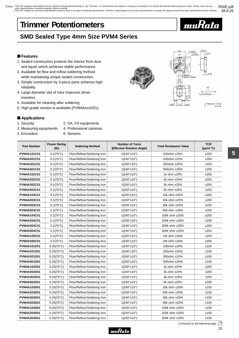
Trimmer PotentiometersSMD Sealed Type 4mm Size PVM4 Series
#2
#1 #3CLOCKWISE
#1
#2
#3
4.0
2.7±
0.1
(2.4
) 4.7
2.0±0.2
0.7
0.750.55±0.1
0.6
0.8
1.5
2.4
(0.3
)
0.85 1.8 0.85
0.35±0.1 Depth1.7
3.8 Dia.1.5 Dia.
Tolerance : ±0.3 ( in mm)
Part NumberPower Rating
(W)Soldering Method
Number of Turns(Effective Rotation Angle)
Total Resistance ValueTCR
(ppm/°C)
PVM4A101C01 0.1(70°C) Flow/Reflow/Soldering Iron 1(240°±10°) 100ohm ±25% ±250
PVM4A201C01 0.1(70°C) Flow/Reflow/Soldering Iron 1(240°±10°) 200ohm ±25% ±250
PVM4A301C01 0.1(70°C) Flow/Reflow/Soldering Iron 1(240°±10°) 300ohm ±25% ±250
PVM4A501C01 0.1(70°C) Flow/Reflow/Soldering Iron 1(240°±10°) 500ohm ±25% ±250
PVM4A102C01 0.1(70°C) Flow/Reflow/Soldering Iron 1(240°±10°) 1k ohm ±25% ±250
PVM4A202C01 0.1(70°C) Flow/Reflow/Soldering Iron 1(240°±10°) 2k ohm ±25% ±250
PVM4A302C01 0.1(70°C) Flow/Reflow/Soldering Iron 1(240°±10°) 3k ohm ±25% ±250
PVM4A502C01 0.1(70°C) Flow/Reflow/Soldering Iron 1(240°±10°) 5k ohm ±25% ±250
PVM4A103C01 0.1(70°C) Flow/Reflow/Soldering Iron 1(240°±10°) 10k ohm ±25% ±250
PVM4A203C01 0.1(70°C) Flow/Reflow/Soldering Iron 1(240°±10°) 20k ohm ±25% ±250
PVM4A303C01 0.1(70°C) Flow/Reflow/Soldering Iron 1(240°±10°) 30k ohm ±25% ±250
PVM4A503C01 0.1(70°C) Flow/Reflow/Soldering Iron 1(240°±10°) 50k ohm ±25% ±250
PVM4A104C01 0.1(70°C) Flow/Reflow/Soldering Iron 1(240°±10°) 100k ohm ±25% ±250
PVM4A204C01 0.1(70°C) Flow/Reflow/Soldering Iron 1(240°±10°) 200k ohm ±25% ±250
PVM4A304C01 0.1(70°C) Flow/Reflow/Soldering Iron 1(240°±10°) 300k ohm ±25% ±250
PVM4A504C01 0.1(70°C) Flow/Reflow/Soldering Iron 1(240°±10°) 500k ohm ±25% ±250
PVM4A105C01 0.1(70°C) Flow/Reflow/Soldering Iron 1(240°±10°) 1M ohm ±25% ±250
PVM4A205C01 0.1(70°C) Flow/Reflow/Soldering Iron 1(240°±10°) 2M ohm ±25% ±250
PVM4A101D01 0.25(70°C) Flow/Reflow/Soldering Iron 1(240°±10°) 100ohm ±20% ±100
PVM4A201D01 0.25(70°C) Flow/Reflow/Soldering Iron 1(240°±10°) 200ohm ±20% ±100
PVM4A301D01 0.25(70°C) Flow/Reflow/Soldering Iron 1(240°±10°) 300ohm ±20% ±100
PVM4A501D01 0.25(70°C) Flow/Reflow/Soldering Iron 1(240°±10°) 500ohm ±20% ±100
PVM4A102D01 0.25(70°C) Flow/Reflow/Soldering Iron 1(240°±10°) 1k ohm ±20% ±200
PVM4A202D01 0.25(70°C) Flow/Reflow/Soldering Iron 1(240°±10°) 2k ohm ±20% ±200
PVM4A302D01 0.25(70°C) Flow/Reflow/Soldering Iron 1(240°±10°) 3k ohm ±20% ±200
PVM4A502D01 0.25(70°C) Flow/Reflow/Soldering Iron 1(240°±10°) 5k ohm ±20% ±200
PVM4A103D01 0.25(70°C) Flow/Reflow/Soldering Iron 1(240°±10°) 10k ohm ±20% ±150
PVM4A203D01 0.25(70°C) Flow/Reflow/Soldering Iron 1(240°±10°) 20k ohm ±20% ±150
PVM4A303D01 0.25(70°C) Flow/Reflow/Soldering Iron 1(240°±10°) 30k ohm ±20% ±150
PVM4A503D01 0.25(70°C) Flow/Reflow/Soldering Iron 1(240°±10°) 50k ohm ±20% ±150
PVM4A104D01 0.25(70°C) Flow/Reflow/Soldering Iron 1(240°±10°) 100k ohm ±20% ±150
PVM4A204D01 0.25(70°C) Flow/Reflow/Soldering Iron 1(240°±10°) 200k ohm ±20% ±150
PVM4A304D01 0.25(70°C) Flow/Reflow/Soldering Iron 1(240°±10°) 300k ohm ±20% ±150
Continued on the following page.
Features1. Sealed construction protects the interior from dust and liquid, which achieves stable performance.2. Available for flow and reflow soldering method while maintaining unique sealed construction.3. Simple construction by 3-piece parts achieves high reliability.4. Large diameter slot of rotor improves driver insertion.5. Available for cleaning after soldering6. High grade version is available (PVM4AxxxD01).
Applications1. Security 2. OA, FA equipments3. Measuring equipments 4. Professional cameras5. Encorders 6. Sensors
• This PDF catalog is downloaded from the website of Murata Manufacturing co., ltd. Therefore, it’s specifications are subject to change or our products in it may be discontinued without advance notice. Please check with our sales representatives or product engineers before ordering.
• This PDF catalog has only typical specifications because there is no space for detailed specifications. Therefore, please approve our product specifications or transact the approval sheet for product specifications before ordering.
!Note R50E.pdf08.8.26

24
5
!Note • Please read rating and !CAUTION (for storage, operating, rating, soldering, mounting and handling) in this catalog to prevent smoking and/or burning, etc.• This catalog has only typical specifications because there is no space for detailed specifications. Therefore, please approve our product specifications or transact the approval sheet for product specifications before ordering.
Part NumberPower Rating
(W)Soldering Method
Number of Turns(Effective Rotation Angle)
Total Resistance ValueTCR
(ppm/°C)
Continued from the preceding page.
PVM4A504D01 0.25(70°C) Flow/Reflow/Soldering Iron 1(240°±10°) 500k ohm ±20% ±150
PVM4A105D01 0.25(70°C) Flow/Reflow/Soldering Iron 1(240°±10°) 1M ohm ±20% ±150
PVM4A205D01 0.25(70°C) Flow/Reflow/Soldering Iron 1(240°±10°) 2M ohm ±20% ±150
Operating Temperature Range: -55 to 125 °CThe last three digits express the individual specification codes. C01 for standard type and D01 for high-liability type.
Construction
Rotor
#1 Terminal
#3 Terminal
#2 Terminal
Wiper
ResistiveElement
CeramicSubstrate
Rubber
Standard Land Pattern
1.7
1.8
3.2
1.2
3.2
1.11.61.1 Tolerance : ±0.1 ( in mm)
CharacteristicsItem PVM4ApppC01 PVM4ApppD01
Humidity Exposure
High Temperature Exposure
Humidity Load Life
Temperature Load Life
Temperature Cycle
Res. Change: ±3%
Res. Change: ±3%
Res. Change: ±3%
Res. Change: ±3%
Res. Change: ±3%
Res. Change: ±10% (20 cycles)Rotational Life
Res. Change: ±2%
Res. Change: ±2%
Res. Change: ±3%
Res. Change: ±3%
Res. Change: ±2%
Res. Change: ±5% (100 cycles)
• This PDF catalog is downloaded from the website of Murata Manufacturing co., ltd. Therefore, it’s specifications are subject to change or our products in it may be discontinued without advance notice. Please check with our sales representatives or product engineers before ordering.
• This PDF catalog has only typical specifications because there is no space for detailed specifications. Therefore, please approve our product specifications or transact the approval sheet for product specifications before ordering.
!Note R50E.pdf08.8.26

PVM4 Series Notice
25
5
!Note • Please read rating and !CAUTION (for storage, operating, rating, soldering, mounting and handling) in this catalog to prevent smoking and/or burning, etc.• This catalog has only typical specifications because there is no space for detailed specifications. Therefore, please approve our product specifications or transact the approval sheet for product specifications before ordering.
Notice (Operating and Storage Conditions)
Notice (Rating)1. When using with partial load (rheostat), minimize the power depending on the resistance value.2. The maximum input voltage to a trimmer potentiometer should not exceed (P•R)^1/2 or the maximum operating voltage, whichever is smaller.
Notice (Soldering and Mounting)
1. Store in temperatures of -10 to +40 deg. C and relative humidity of 30-85%.2. Do not store in or near corrosive gases.3. Use within six months after delivery. 4. Open the package just before using.5. Do not store under direct sunlight.6. If you use the trimmer potentiometer in an environment other than listed below, please consult with a Murata factory representative prior to using. The trimmer potentiometer should not be used under the following environmental conditions:
(1) Corrosive gaseous atmosphere (Ex. Chlorine gas, Hydrogen sulfide gas, Ammonia gas, Sulfuric acid gas, Nitric oxide gas, etc.) (2) In liquid (Ex. Oil, Medical liquid, Organic solvent, etc.) (3) Dusty/dirty atmosphere (4) Direct sunlight (5) Static voltage nor electric/magnetic fields (6) Direct sea breeze (7) Other variations of the above
1. Soldering (1) Can be soldered by reflow soldering method, flow soldering method, and soldering iron. (2) Use our standard land dimension. Excessive land area causes displacement due to the effect of the surface tension of the solder. Insufficient land area leads to insufficient soldering strength of the chip. (3) Soldering condition Refer to the temperature profile. If the soldering conditions are not suitable, e.g., excessive time and/or excessive temperature, the trimmer potentiometer may deviate from the specified characteristics. (4) Apply the appropriate amount of solder paste. The thickness of solder paste should be printed from 100 micro m to 150 micro m and the dimension of land pattern used should be Murata's standard land pattern at reflow soldering. Insufficient amounts of solder can lead to insufficient soldering strength on PCB. Excessive amounts of solder may cause bridging between the terminals.
(5) The soldering iron should not come in contact with the case of the trimmer potentiometer. If such contact does occur, the trimmer potentiometer may be damaged.2. Mounting (1) Do not apply excessive force, preferably 9.8N max. (Ref. 1kgf) when the trimmer potentiometer is mounted to the PCB. (2) Do not warp and/or bend PC board to prevent trimmer potentiometer from breakage. (3) In chip placers, the recommended size of the cylindrical pick-up nozzle should be outer dimension 4.0mm dia. and inner dimension 2.0mm dia.3. Cleaning Isopropyl alcohol and Ethyl alcohol are available materials for cleaning. For other materials, please consult with a Murata factory representative prior to using.
• This PDF catalog is downloaded from the website of Murata Manufacturing co., ltd. Therefore, it’s specifications are subject to change or our products in it may be discontinued without advance notice. Please check with our sales representatives or product engineers before ordering.
• This PDF catalog has only typical specifications because there is no space for detailed specifications. Therefore, please approve our product specifications or transact the approval sheet for product specifications before ordering.
!Note R50E.pdf08.8.26

PVM4 Series Notice
26
5
!Note • Please read rating and !CAUTION (for storage, operating, rating, soldering, mounting and handling) in this catalog to prevent smoking and/or burning, etc.• This catalog has only typical specifications because there is no space for detailed specifications. Therefore, please approve our product specifications or transact the approval sheet for product specifications before ordering.
Soldering Profile
Tem
pera
ture
(°C
)
t3
t2
T3T2
T5
T4
T1
Time (s)t1
1. Soldering profile for Lead-free solder (96.5Sn/3.0Ag/0.5Cu)
Standard Profile
Pre-heating Heating Cycleof Reflow
Time°C
Temp. (T1)
°C
Time (t1)
sec.
Temp. (T2)
°C
Time (t2)
sec.
2245±3150 to 180 60 to 120 220 30 to 60
Limit Profile
Standard Profile
Pre-heating Heating
Time°C
Temp. (T1)
°C
Time (t1)
sec.
Temp. (T4)
°C
Time (t3)
sec.
Limit Profile
2260 +5/-0150 to 180 60 to 120 230 30 to 50
Standard Profile
Pre-heating Heating
Time°C
Temp. (T1)
°C
Time (t1)
sec.
Temp. (T2)
°C
Time (t2)
sec.
1230150 60 to 120 183 30Tem
pera
ture
(°C
)
Time (s)
Standard Profile
t1
T1 t2
T3
T2
2. Soldering profile for Eutectic solder (63Sn/37Pb)
(Limit profile: refer to 1)
Standard Condition
Temperature of Soldering Iron Tip
°C
Soldering Time
sec.
Soldering Iron Power Output
W
350±10 3 max. 30 max. 1
Cycle of Soldering Iron
Time
Reflow Soldering Profile
Flow Soldering Profile
PeakTemperature
(T3)
PeakTemperature
(T3)
Cycleof Reflow
PeakTemperature
(T5)
Soldering Iron
Cycleof Reflow
Soldering profile for Lead-free solder (96.5Sn/3.0Ag/0.5Cu), Eutectic solder (63Sn/37Pb)
Standard Profile
Pre-heating Heating
Temp. (T1)
°C
Time (t1)
sec.
Temp. (T2)
°C
Time (t2)
sec.
150 60 to 120 250 5 max. 1
Tem
pera
ture
(°C
)
t1
t2
T3T2
T1
Time (s)
Limit Profile
Standard Profile
Cycleof Flow
Time
Limit Profile
Pre-heating Heating
Temp. (T1)
°C
Time (t1)
sec.
Temp. (T3)
°C
Time (t2)
sec.
150 60 to 120 265±3 5 max. 2
Cycleof Flow
Time
Heating
Pre-heating
Series
PVM4
Series
PVM4
Series
PVM4
Series
PVM4
• This PDF catalog is downloaded from the website of Murata Manufacturing co., ltd. Therefore, it’s specifications are subject to change or our products in it may be discontinued without advance notice. Please check with our sales representatives or product engineers before ordering.
• This PDF catalog has only typical specifications because there is no space for detailed specifications. Therefore, please approve our product specifications or transact the approval sheet for product specifications before ordering.
!Note R50E.pdf08.8.26

PVM4 Series Notice
27
5
!Note • Please read rating and !CAUTION (for storage, operating, rating, soldering, mounting and handling) in this catalog to prevent smoking and/or burning, etc.• This catalog has only typical specifications because there is no space for detailed specifications. Therefore, please approve our product specifications or transact the approval sheet for product specifications before ordering.
Notice (Handling)
Notice (Other)1. Please make sure that your product has been evaluated and confirmed against your specifications when our product is mounted to your product.2. Murata cannot guarantee trimmer potentiometer integrity when used under conditions other than those specified in this document.
1. Use suitable screwdrivers that fit comfortably in driver slot. We recommend the screwdriver below. * Recommended screwdriver for manual adjustment VESSEL MFG.: NO. 9000-2.6x30 (Murata P/N: KMDR120) We can supply the screwdrivers above. If you place order, please specify the Murata P/N.2. Do not apply more than 4.9N (Ref. 500gf) of twist and stress after mounting onto PCB to prevent contact intermittence. If excessive force is applied, the trimmer potentiometer may not function.
3. Please use within the effective rotational angle. The potentiometer does not have a mechanical stop for over rotation. In cases out of effective rotational angle, the trimmer potentiometer may not function.4. When using a lock paint to fix slot position, please use adhesive resin without chlorine or sulfur (Three-bond "1401 series") and evaluate performance with your product. Lock paint may cause corrosion or electrical contact problems.
• This PDF catalog is downloaded from the website of Murata Manufacturing co., ltd. Therefore, it’s specifications are subject to change or our products in it may be discontinued without advance notice. Please check with our sales representatives or product engineers before ordering.
• This PDF catalog has only typical specifications because there is no space for detailed specifications. Therefore, please approve our product specifications or transact the approval sheet for product specifications before ordering.
!Note R50E.pdf08.8.26

28
6
!Note • Please read rating and !CAUTION (for storage, operating, rating, soldering, mounting and handling) in this catalog to prevent smoking and/or burning, etc.• This catalog has only typical specifications because there is no space for detailed specifications. Therefore, please approve our product specifications or transact the approval sheet for product specifications before ordering.
Trimmer PotentiometersSMD Sealed Type Multi-turn PVG5 Series
4.8
5.1
3.5
3.9
0.9
Marking
0.2
2.41.2
2.6 3-
0.9
2-0.7
1.1
2-0.
7
0.5
2.5
ADJ. SlotDia. ø1.5Width 0.6Depth 0.5
#2
#3 #1
#2 (Wiper)
#1 #3
Clockwise
Circuit
(Tolerance: ±0.3 in mm)
PVG5A
(Tolerance: ±0.3 in mm)
1.2
2.4
2.3
4.9
3.7
1.1
2-0.
7
2.6
4.8
3-0.
9
3-0.7
0.50
#2 (Wiper)
#1 #3
Clockwise
#1
#2#3
ADJ. SlotDia. ø1.5Width 0.6Depth 0.5
Circuit
Marking
PVG5H
Part NumberPower Rating
(W)Soldering Method
Number of Turns(Effective Rotation Angle)
Total Resistance ValueTCR
(ppm/°C)
PVG5p100C03 0.25(70°C) Reflow/Soldering Iron 11 10ohm ±10% ±150
PVG5p200C03 0.25(70°C) Reflow/Soldering Iron 11 20ohm ±10% ±150
PVG5p500C03 0.25(70°C) Reflow/Soldering Iron 11 50ohm ±10% ±150
PVG5p101C03 0.25(70°C) Reflow/Soldering Iron 11 100ohm ±10% ±150
PVG5p201C03 0.25(70°C) Reflow/Soldering Iron 11 200ohm ±10% ±150
PVG5p501C03 0.25(70°C) Reflow/Soldering Iron 11 500ohm ±10% ±150
PVG5p102C03 0.25(70°C) Reflow/Soldering Iron 11 1k ohm ±10% ±150
PVG5p202C03 0.25(70°C) Reflow/Soldering Iron 11 2k ohm ±10% ±150
PVG5p502C03 0.25(70°C) Reflow/Soldering Iron 11 5k ohm ±10% ±150
PVG5p103C03 0.25(70°C) Reflow/Soldering Iron 11 10k ohm ±10% ±150
PVG5p203C03 0.25(70°C) Reflow/Soldering Iron 11 20k ohm ±10% ±150
PVG5p503C03 0.25(70°C) Reflow/Soldering Iron 11 50k ohm ±10% ±150
PVG5p104C03 0.25(70°C) Reflow/Soldering Iron 11 100k ohm ±10% ±150
PVG5p204C03 0.25(70°C) Reflow/Soldering Iron 11 200k ohm ±10% ±150
PVG5p504C03 0.25(70°C) Reflow/Soldering Iron 11 500k ohm ±10% ±150
PVG5p105C03 0.25(70°C) Reflow/Soldering Iron 11 1M ohm ±10% ±150
PVG5p205C03 0.25(70°C) Reflow/Soldering Iron 11 2M ohm ±10% ±150
Operating Temperature Range: -55 to 125 °CThe blank column is filled with the code of adjustment direction A (top) or H (side).
Features1. Sealed construction protects the interior from dust and liquid, which achieves stable performance.2. Available with reflow soldering method3. Available for ultrasonic cleaning after soldering4. Clutch mechanism prevents excessive wiper rotation.5. Both Top and side adjustment directions6. Ultra smaller volume (1/5-1/2) than leaded multi-turn potentiometer.
Applications1. Measuring instruments 2. OA equipment3. Medical equipment 4. Power supply5. Sensors6. Base station for cellular phone
• This PDF catalog is downloaded from the website of Murata Manufacturing co., ltd. Therefore, it’s specifications are subject to change or our products in it may be discontinued without advance notice. Please check with our sales representatives or product engineers before ordering.
• This PDF catalog has only typical specifications because there is no space for detailed specifications. Therefore, please approve our product specifications or transact the approval sheet for product specifications before ordering.
!Note R50E.pdf08.8.26
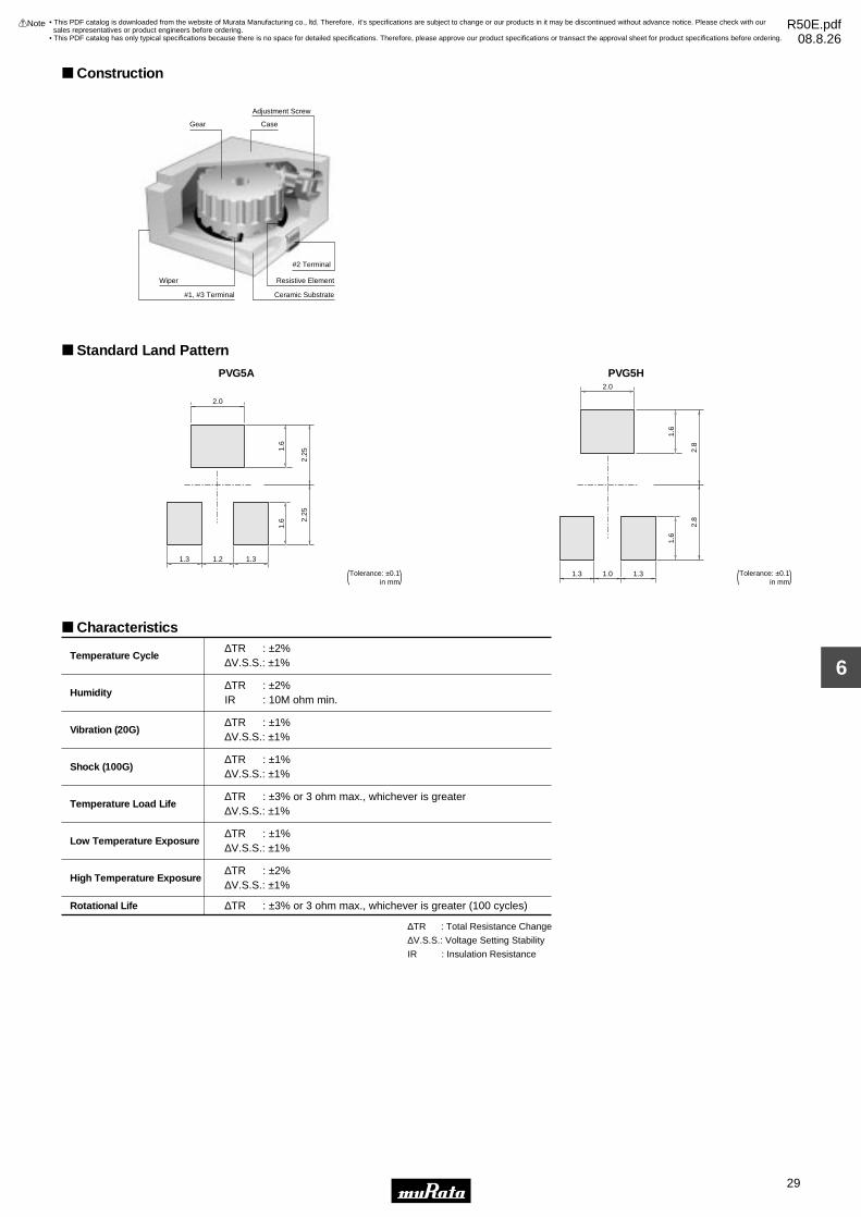
29
6
!Note • Please read rating and !CAUTION (for storage, operating, rating, soldering, mounting and handling) in this catalog to prevent smoking and/or burning, etc.• This catalog has only typical specifications because there is no space for detailed specifications. Therefore, please approve our product specifications or transact the approval sheet for product specifications before ordering.
Construction
#2 Terminal
CaseGear
Adjustment Screw
Resistive ElementWiper
Ceramic Substrate#1, #3 Terminal
Standard Land Pattern
PVG5A
2.0
2.25
2.25
1.31.21.3
1.6
1.6
(Tolerance: ±0.1 in mm)
PVG5H
(Tolerance: ±0.1 in mm)
2.0
2.8
2.8
1.31.01.3
1.6
1.6
Characteristics∆TR : ±2%∆V.S.S.: ±1%
∆TR : ±2%IR : 10M ohm min.
∆TR : ±1%∆V.S.S.: ±1%
∆TR : ±1%∆V.S.S.: ±1%
∆TR : ±3% or 3 ohm max., whichever is greater∆V.S.S.: ±1%
∆TR : ±1%∆V.S.S.: ±1%
∆TR : ±2%∆V.S.S.: ±1%
∆TR : ±3% or 3 ohm max., whichever is greater (100 cycles)
Temperature Cycle
Humidity
Vibration (20G)
Shock (100G)
Temperature Load Life
Low Temperature Exposure
High Temperature Exposure
Rotational Life
∆TR : Total Resistance Change
∆V.S.S.: Voltage Setting Stability
IR : Insulation Resistance
• This PDF catalog is downloaded from the website of Murata Manufacturing co., ltd. Therefore, it’s specifications are subject to change or our products in it may be discontinued without advance notice. Please check with our sales representatives or product engineers before ordering.
• This PDF catalog has only typical specifications because there is no space for detailed specifications. Therefore, please approve our product specifications or transact the approval sheet for product specifications before ordering.
!Note R50E.pdf08.8.26

PVG5 Series Notice
30
6
!Note • Please read rating and !CAUTION (for storage, operating, rating, soldering, mounting and handling) in this catalog to prevent smoking and/or burning, etc.• This catalog has only typical specifications because there is no space for detailed specifications. Therefore, please approve our product specifications or transact the approval sheet for product specifications before ordering.
Notice (Operating and Storage Conditions)
Notice (Rating)1. When using with partial load (rheostat), minimize the power depending on the resistance value.2. The maximum input voltage to a trimmer potentiometer should not exceed (P•R)^1/2 or the maximum operating voltage, whichever is smaller.
Notice (Soldering and Mounting)
1. Store in temperatures of -10 to +40 deg. C and relative humidity of 30-85%.2. Do not store in or near corrosive gases.3. Use within six months after delivery. 4. Open the package just before using.5. Do not store under direct sunlight.6. If you use the trimmer potentiometer in an environment other than listed below, please consult with a Murata factory representative prior to using. The trimmer potentiometer should not be used under the following environmental conditions:
(1) Corrosive gaseous atmosphere (Ex. Chlorine gas, Hydrogen sulfide gas, Ammonia gas, Sulfuric acid gas, Nitric oxide gas, etc.) (2) In liquid (Ex. Oil, Medical liquid, Organic solvent, etc.) (3) Dusty/dirty atmosphere (4) Direct sunlight (5) Static voltage nor electric/magnetic fields (6) Direct sea breeze (7) Other variations of the above
1. Soldering (1) Soldering condition Refer to the temperature profile. If the soldering conditions are not suitable, e.g., excessive time and/or excessive temperature, the trimmer capacitor may deviate from the specified characteristics. (2) Cannot be soldered using the flow soldering method. If you use the flow soldering method, the trimmer potentiometer may not function. (3) The soldering iron should not come in contact with the case of the trimmer potentiometer. If such contact does occur, the trimmer potentiometer may be damaged. (4) Insufficient amounts of solder can lead to insufficient soldering strength on PCB. Excessive amounts of solder may cause bridging between the terminals.
2. Mounting (1) Use our standard land dimension. Excessive land area causes displacement due to the effect of the surface tension of the solder. Insufficient land area leads to insufficient soldering strength of the chip. (2) Do not apply excessive force, preferably 9.8N max. (Ref. 1kgf) when the trimmer potentiometer is mounted to the PCB. (3) Do not warp and/or bend PC board to prevent trimmer potentiometer from breakage. (4) In chip placers, the recommended size of the cylindrical pick-up nozzle should be outer dimension 4.0mm dia. and inner dimension 2.0mm dia.3. Cleaning Isopropyl-alcohol and Ethyl-alcohol are applicable solvents for cleaning. If you use any other types of solvents, please consult with a Murata factory representative prior to using.
• This PDF catalog is downloaded from the website of Murata Manufacturing co., ltd. Therefore, it’s specifications are subject to change or our products in it may be discontinued without advance notice. Please check with our sales representatives or product engineers before ordering.
• This PDF catalog has only typical specifications because there is no space for detailed specifications. Therefore, please approve our product specifications or transact the approval sheet for product specifications before ordering.
!Note R50E.pdf08.8.26

PVG5 Series Notice
31
6
!Note • Please read rating and !CAUTION (for storage, operating, rating, soldering, mounting and handling) in this catalog to prevent smoking and/or burning, etc.• This catalog has only typical specifications because there is no space for detailed specifications. Therefore, please approve our product specifications or transact the approval sheet for product specifications before ordering.
Soldering Profile
Tem
pera
ture
(°C
)
t3
t2
T3T2
T5
T4
T1
Time (s)t1
1. Soldering profile for Lead-free solder (96.5Sn/3.0Ag/0.5Cu)
Standard Profile
Pre-heating Heating
Time°C
Series
PVG5
Temp. (T1)
°C
Time (t1)
sec.
Temp. (T2)
°C
Time (t2)
sec.
Pre-heating Heating
Time°C
Temp. (T1)
°C
Time (t1)
sec.
Temp. (T4)
°C
Time (t3)
sec.
Limit Profile
2245±3150 to 180 60 to 120 220 30 to 60 2260 +5/-0150 to 180 60 to 120 230 30 to 50
Limit Profile
Standard Profile
Tem
pera
ture
(°C
)
Time (s)
Standard Profile
t1
T1 t2
T3
T2
2. Soldering profile for Eutectic solder (63Sn/37Pb)
(Limit profile: refer to 1)
Standard Condition
Temperature of Soldering Iron Tip
°C
Soldering Time
sec.
Soldering Iron Power Output
W
350±10 3 max. 30 max. 1
Cycle of Soldering Iron
Time
Reflow Soldering Profile
Cycle ofReflow
Cycle ofReflow
PeakTemperature
(T3)
PeakTemperature
(T5)
Soldering Iron
Standard Profile
Pre-heating Heating
Time°C
Series
PVG5
Temp. (T1)
°C
Time (t1)
sec.
Temp. (T2)
°C
Time (t2)
sec.
Series
PVG5
1230150 60 to 120 183 30
Cycle ofReflow
PeakTemperature
(T3)
Notice (Handling)
Notice (Other)1. Please make sure that your product has been evaluated and confirmed against your specifications when our product is mounted to your product.
2. Murata cannot guarantee trimmer potentiometer integrity when used under conditions other than those specified in this document.
1. Use suitable screwdrivers that fit comfortably in driver slot. We recommend the screwdrivers below. * Recommended screwdrivers for manual adjustment <PVG5 series> VESSEL MFG.: NO.9000-1.3x30 (Murata P/N: KMDR130) We can supply the screwdrivers above. If you place order, please specify Murata P/N.2. Do not apply more than 9.8N (Ref. 1kgf) of twist and stress after mounting onto PCB to prevent contact intermittence. If excessive force is applied, the trimmer potentiometer may not function.
3. When adjusting with a screwdriver, do not apply excessive force, preferable 4.9N max. (Ref 500gf).4. When using a lock paint to fix slot position, please use adhesive resin without chlorine or sulfur (Three-bond "1401 series") and evaluate performance with your product. Lock paint may cause corrosion or electrical problems.
• This PDF catalog is downloaded from the website of Murata Manufacturing co., ltd. Therefore, it’s specifications are subject to change or our products in it may be discontinued without advance notice. Please check with our sales representatives or product engineers before ordering.
• This PDF catalog has only typical specifications because there is no space for detailed specifications. Therefore, please approve our product specifications or transact the approval sheet for product specifications before ordering.
!Note R50E.pdf08.8.26

32
7
!Note • Please read rating and !CAUTION (for storage, operating, rating, soldering, mounting and handling) in this catalog to prevent smoking and/or burning, etc.• This catalog has only typical specifications because there is no space for detailed specifications. Therefore, please approve our product specifications or transact the approval sheet for product specifications before ordering.
Trimmer PotentiometersLead Sealed Type Single-turn PV32 Series
#1#2 #3
0.6
2.8
Dia
.4.
1±0.
34.
6±0.
30.
35 m
ax.
8.0±
1.0
0.4
CL
90°±6°
6.6±0.5 Dia.
2.5 2.5
1.0 Depth
3−0.5±0.1 Dia.
0.9 Dia. max.
( Tolerance : ±0.3)in mm
#2
#1 #3CLOCKWISE
PV32H
0.6
2.8
Dia
.1.0 Depth
#2
#1 #3CLOCKWISE
#1 #2 #3
2.5
6.6±0.5 Dia.
7.0±
1.0
5.5±
0.3
6.0±
0.3
0.2
3−0.5±0.1 Dia.
2.5 Tolerance : ±0.3 ( in mm)
PV32R
0.6
2.8
Dia
.1.0 Depth
#2
#1 #3CLOCKWISE
#1 #2 #3
2.5
6.6±0.5 DIA.
7.0±
1.0
2.5
5.5±
0.3
6.0±
0.3
0.2
3−0.5±0.1 Dia.
2.5 Tolerance : ±0.3 ( in mm)
PV32P
#2
#1 #3CLOCKWISE
#1#2#3
6.95.9±0.4
5.0±
1.0
2.5
0.61.0 Depth
6.0±
1.0
4.7±
0.3
8.0±
0.3
0.2±
0.1
2.8
Dia
.
5.0
6.4±0.4
3−0.5±0.1 Dia.
2.52.5
1.0
Tolerance : ±0.3 ( in mm)
PV32N
#2
#1 #3CLOCKWISE
#1 #2 #3
6.95.9±0.4
6.5±
1.0
2.5
0.61.0 Depth
8.0±
1.0
4.7±
0.3
8.0±
0.3
0.2±
0.1
2.8
Dia
.
5.0
6.4±0.4
3−0.5±0.1 Dia.
2.52.5
1.0
Tolerance : ±0.3 ( in mm)
PV32S
#2
#1 #3CLOCKWISE
#1 #2 #3
6.95.9±0.4
5.5±
1.0
2.5
0.61.0 Depth
8.0±
1.0
4.7±
0.3
8.0±
0.3
0.2±
0.1
2.8
Dia
.
5.0
6.4±0.4
3−0.5±0.1 Dia.
2.52.5
1.0
Tolerance : ±0.3 ( in mm)
PV32T
Features1. 6 standard terminal styles2. Round shaped body enables smaller area mount than same 6mm square potentiometer. 3. Sealed construction protects the interior from dust and liquid, which achieves stable performance.4. Available for ultrasonic cleaning after soldering5. Flammability: UL94V-0
Applications1. HDTVs 2. Professional cameras 3. CATV 4. FAX5. Printers 6. Sensors 7. Power supply
• This PDF catalog is downloaded from the website of Murata Manufacturing co., ltd. Therefore, it’s specifications are subject to change or our products in it may be discontinued without advance notice. Please check with our sales representatives or product engineers before ordering.
• This PDF catalog has only typical specifications because there is no space for detailed specifications. Therefore, please approve our product specifications or transact the approval sheet for product specifications before ordering.
!Note R50E.pdf08.8.26

33
7
!Note • Please read rating and !CAUTION (for storage, operating, rating, soldering, mounting and handling) in this catalog to prevent smoking and/or burning, etc.• This catalog has only typical specifications because there is no space for detailed specifications. Therefore, please approve our product specifications or transact the approval sheet for product specifications before ordering.
Part NumberPower Rating
(W)Soldering Method
Number of Turns(Effective Rotation Angle)
Total Resistance ValueTCR
(ppm/°C)
PV32p100A01 0.5(70°C) Flow/Soldering Iron 1(230°±5°) 10ohm ±20% ±100
PV32p200A01 0.5(70°C) Flow/Soldering Iron 1(230°±5°) 20ohm ±20% ±100
PV32p250A01 0.5(70°C) Flow/Soldering Iron 1(230°±5°) 25ohm ±20% ±100
PV32p500A01 0.5(70°C) Flow/Soldering Iron 1(230°±5°) 50ohm ±20% ±100
PV32p101A01 0.5(70°C) Flow/Soldering Iron 1(230°±5°) 100ohm ±20% ±100
PV32p201A01 0.5(70°C) Flow/Soldering Iron 1(230°±5°) 200ohm ±20% ±100
PV32p251A01 0.5(70°C) Flow/Soldering Iron 1(230°±5°) 250ohm ±20% ±100
PV32p501A01 0.5(70°C) Flow/Soldering Iron 1(230°±5°) 500ohm ±20% ±100
PV32p102A01 0.5(70°C) Flow/Soldering Iron 1(230°±5°) 1k ohm ±20% ±100
PV32p202A01 0.5(70°C) Flow/Soldering Iron 1(230°±5°) 2k ohm ±20% ±100
PV32p252A01 0.5(70°C) Flow/Soldering Iron 1(230°±5°) 2.5k ohm ±20% ±100
PV32p502A01 0.5(70°C) Flow/Soldering Iron 1(230°±5°) 5k ohm ±20% ±100
PV32p103A01 0.5(70°C) Flow/Soldering Iron 1(230°±5°) 10k ohm ±20% ±100
PV32p203A01 0.5(70°C) Flow/Soldering Iron 1(230°±5°) 20k ohm ±20% ±100
PV32p253A01 0.5(70°C) Flow/Soldering Iron 1(230°±5°) 25k ohm ±20% ±100
PV32p503A01 0.5(70°C) Flow/Soldering Iron 1(230°±5°) 50k ohm ±20% ±100
PV32p104A01 0.5(70°C) Flow/Soldering Iron 1(230°±5°) 100k ohm ±20% ±100
PV32p204A01 0.5(70°C) Flow/Soldering Iron 1(230°±5°) 200k ohm ±20% ±100
PV32p254A01 0.5(70°C) Flow/Soldering Iron 1(230°±5°) 250k ohm ±20% ±100
PV32p504A01 0.5(70°C) Flow/Soldering Iron 1(230°±5°) 500k ohm ±20% ±100
PV32p105A01 0.5(70°C) Flow/Soldering Iron 1(230°±5°) 1M ohm ±20% ±100
PV32p205A01 0.5(70°C) Flow/Soldering Iron 1(230°±5°) 2M ohm ±20% ±100
PV32p505A01 0.5(70°C) Flow/Soldering Iron 1(230°±5°) 5M ohm ±20% ±100
Operating Temperature Range: -55 to 125 °CThe blank column is filled with the code of adjustment direction and lead type (H, P, R, N, S and T).
The order quantity should be an integral multiple of the "Minimum Quantity".
Construction
"O"-Ring
ResistiveElement
Rotor
Cover
Terminal
Wiper
CeramicSubstrate
Standard Mounting Holes
PV32H
(1) (3)
(2)
2.52.
5
3-0.9
Tolerance: ±0.1in mm
PV32R
2.5
3-0.9
2.5
(2)(1) (3)
Tolerance: ±0.1in mm
Continued on the following page.
• This PDF catalog is downloaded from the website of Murata Manufacturing co., ltd. Therefore, it’s specifications are subject to change or our products in it may be discontinued without advance notice. Please check with our sales representatives or product engineers before ordering.
• This PDF catalog has only typical specifications because there is no space for detailed specifications. Therefore, please approve our product specifications or transact the approval sheet for product specifications before ordering.
!Note R50E.pdf08.8.26

34
7
!Note • Please read rating and !CAUTION (for storage, operating, rating, soldering, mounting and handling) in this catalog to prevent smoking and/or burning, etc.• This catalog has only typical specifications because there is no space for detailed specifications. Therefore, please approve our product specifications or transact the approval sheet for product specifications before ordering.
Continued from the preceding page.
Standard Mounting Holes
PV32P/PV32S
2.5
3-0.9
2.5
2.5
(2)
(1)
(3)
Tolerance: ±0.1in mm
PV32N
(3)
(1)
(2)
2.53-0.9
2.5
2.5
Tolerance: ±0.1in mm
PV32T
2.5 2.5
2.5
3-0.9
(2)
(3)
(1)
Tolerance: ±0.1in mm
Characteristics∆TR : ±2%∆V.S.S.: ±1%
∆TR : ±2%IR : 100M ohm min.
∆TR : ±1%∆V.S.S.: ±1%
∆TR : ±1%∆V.S.S.: ±1%
∆TR : ±2%∆V.S.S.: ±2%
∆TR : ±2%∆V.S.S.: ±1%
∆TR : ±2%∆V.S.S.: ±1%
∆TR : ±4% (200 cycles)
Temperature Cycle
Humidity
Vibration (20G)
Shock (100G)
Temperature Load Life
Low Temperature Exposure
High Temperature Exposure
Rotational Life
∆TR : Total Resistance Change
∆V.S.S.: Voltage Setting Stability
IR : Insulation Resistance
• This PDF catalog is downloaded from the website of Murata Manufacturing co., ltd. Therefore, it’s specifications are subject to change or our products in it may be discontinued without advance notice. Please check with our sales representatives or product engineers before ordering.
• This PDF catalog has only typical specifications because there is no space for detailed specifications. Therefore, please approve our product specifications or transact the approval sheet for product specifications before ordering.
!Note R50E.pdf08.8.26
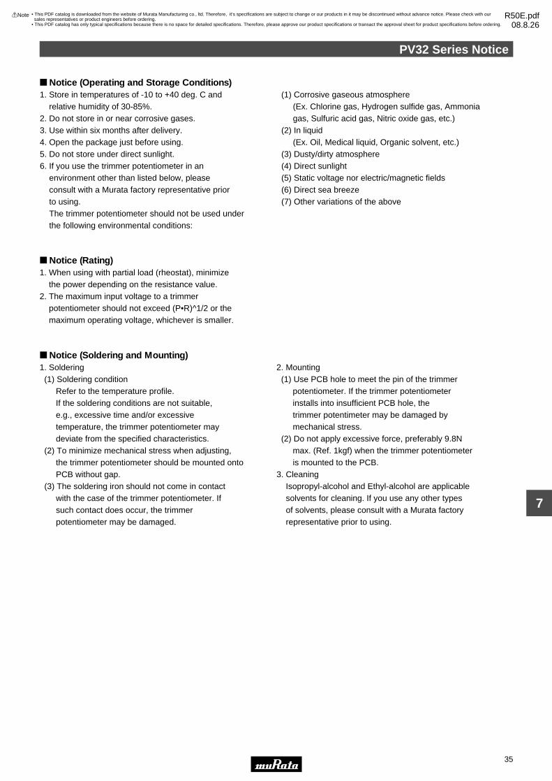
PV32 Series Notice
35
7
!Note • Please read rating and !CAUTION (for storage, operating, rating, soldering, mounting and handling) in this catalog to prevent smoking and/or burning, etc.• This catalog has only typical specifications because there is no space for detailed specifications. Therefore, please approve our product specifications or transact the approval sheet for product specifications before ordering.
Notice (Operating and Storage Conditions)
Notice (Rating)1. When using with partial load (rheostat), minimize the power depending on the resistance value.2. The maximum input voltage to a trimmer potentiometer should not exceed (P•R)^1/2 or the maximum operating voltage, whichever is smaller.
Notice (Soldering and Mounting)1. Soldering (1) Soldering condition Refer to the temperature profile. If the soldering conditions are not suitable, e.g., excessive time and/or excessive temperature, the trimmer potentiometer may deviate from the specified characteristics. (2) To minimize mechanical stress when adjusting, the trimmer potentiometer should be mounted onto PCB without gap. (3) The soldering iron should not come in contact with the case of the trimmer potentiometer. If such contact does occur, the trimmer potentiometer may be damaged.
2. Mounting (1) Use PCB hole to meet the pin of the trimmer potentiometer. If the trimmer potentiometer installs into insufficient PCB hole, the trimmer potentimeter may be damaged by mechanical stress. (2) Do not apply excessive force, preferably 9.8N max. (Ref. 1kgf) when the trimmer potentiometer is mounted to the PCB.3. Cleaning Isopropyl-alcohol and Ethyl-alcohol are applicable solvents for cleaning. If you use any other types of solvents, please consult with a Murata factory representative prior to using.
1. Store in temperatures of -10 to +40 deg. C and relative humidity of 30-85%.2. Do not store in or near corrosive gases.3. Use within six months after delivery. 4. Open the package just before using.5. Do not store under direct sunlight.6. If you use the trimmer potentiometer in an environment other than listed below, please consult with a Murata factory representative prior to using. The trimmer potentiometer should not be used under the following environmental conditions:
(1) Corrosive gaseous atmosphere (Ex. Chlorine gas, Hydrogen sulfide gas, Ammonia gas, Sulfuric acid gas, Nitric oxide gas, etc.) (2) In liquid (Ex. Oil, Medical liquid, Organic solvent, etc.) (3) Dusty/dirty atmosphere (4) Direct sunlight (5) Static voltage nor electric/magnetic fields (6) Direct sea breeze (7) Other variations of the above
• This PDF catalog is downloaded from the website of Murata Manufacturing co., ltd. Therefore, it’s specifications are subject to change or our products in it may be discontinued without advance notice. Please check with our sales representatives or product engineers before ordering.
• This PDF catalog has only typical specifications because there is no space for detailed specifications. Therefore, please approve our product specifications or transact the approval sheet for product specifications before ordering.
!Note R50E.pdf08.8.26

PV32 Series Notice
36
7
!Note • Please read rating and !CAUTION (for storage, operating, rating, soldering, mounting and handling) in this catalog to prevent smoking and/or burning, etc.• This catalog has only typical specifications because there is no space for detailed specifications. Therefore, please approve our product specifications or transact the approval sheet for product specifications before ordering.
Soldering Profile Flow Soldering ProfileSoldering profile for Lead-free solder (96.5Sn/3.0Ag/0.5Cu), Eutectic solder (63Sn/37Pb)
Tem
pera
ture
(°C
)
t1
t2
T3T2
T1
Time (s)
Limit Profile
Standard Profile
Heating
Pre-heating
Standard Profile
Pre-heating Heating
Temp. (T1)
°C
Time (t1)
sec.
Temp. (T2)
°C
Time (t2)
sec.
150 60 to 120 250 5 max. 1
Cycleof Flow
Time
Limit Profile
Pre-heating Heating
Temp. (T1)
°C
Time (t1)
sec.
Temp. (T3)
°C
Time (t2)
sec.
150 60 to 120 260 3 max. 1
Cycleof Flow
Time
Standard Condition
Temperature of Soldering Iron Tip
°C
Soldering Time
sec.
Soldering Iron Power Output
W
350±10 3 max. 30 max. 1
Cycle of Soldering Iron
Time
Soldering Iron
Series
PV32
Series
PV32
Notice (Handling)1. Use suitable screwdrivers that fit comfortably in driver slot. We recommend the screwdrivers below. * Recommended screwdriver for manual adjustment <PV32 series> ENGINEER INC.: DA-40 (Murata P/N: KMDR180) We can supply the screwdrivers above. If you place an order, please specify the Murata P/N.2. Do not apply more than 9.8N (Ref. 1kgf) of twist and stress after mounting onto PCB to prevent contact intermittence. If excessive force is applied, the trimmer potentiometer may not function.
3. When adjusting with an adjustment tool, the applied force to the adjustment screw should not exceed 4.9N (Ref. 500gf). If excessive force is applied, the trimmer potentiometer may not function due to damage.4. The rotational torque at the position of the adjustment range should not exceed the stop strength.5. When using a lock paint to fix slot position, please use adhesive resin without chlorine or sulfur (Three-bond "1401 series") and evaluate performance with your product. Lock paint may cause corrosion or electrical contact problems.
Notice (Other)1. Please make sure that your product has been evaluated and confirmed against your specifications when our product is mounted to your product.2. Murata cannot guarantee trimmer potentiometer integrity when used under conditions other than those specified in this document.
• This PDF catalog is downloaded from the website of Murata Manufacturing co., ltd. Therefore, it’s specifications are subject to change or our products in it may be discontinued without advance notice. Please check with our sales representatives or product engineers before ordering.
• This PDF catalog has only typical specifications because there is no space for detailed specifications. Therefore, please approve our product specifications or transact the approval sheet for product specifications before ordering.
!Note R50E.pdf08.8.26

37
8
!Note • Please read rating and !CAUTION (for storage, operating, rating, soldering, mounting and handling) in this catalog to prevent smoking and/or burning, etc.• This catalog has only typical specifications because there is no space for detailed specifications. Therefore, please approve our product specifications or transact the approval sheet for product specifications before ordering.
Trimmer PotentiometersLead Sealed Type Multi-turn PV12/PV37/PV36 Series
PV12 Series
#2
#1 #3
CLOCKWISE
#1
#2
#3
0.6±0.10.7±0.1 Depth
2.5±
0.1
7.6±
0.1
Dia
.
6.6±0.1 7.0±1.0
0.5
3−0.
5±0.
1 D
ia.
0.4±
0.1
90°±6°
2.5±0
.2 2.5±0.2
Tolerance : ±0.3 ( in mm)PV12H
#2
#1 #3
CLOCKWISE#1
#2
#3
0.6±0.10.7±0.1 Depth
2.5±
0.1
7.6±
0.1
Dia
.
6.6±0.1 7.0±1.0
0.5
3−0.
5±0.
1 D
ia.
2.5
2.5 2.5
Tolerance : ±0.3 ( in mm)PV12P
#2
#1 #3
CLOCKWISE
#1 #2 #37.6±0.3
0.6±0.1
9.0±
0.3
5.1±
0.3
7.7±0.3
6.3±0.3
3−0.5±0.1 Dia.7.0±
1.0
0.5
2.5±
0.1
3.6
2.5
2.5 2.5
0.7±0.1 Depth
Tolerance : ±0.3 ( in mm)
PV12S
#2
#1 #3
CLOCKWISE
#1 #2 #37.6±0.3
0.6±0.1
9.0±
0.3
5.1±
0.3
7.7±0.3
6.3±0.3
3−0.5±0.1 Dia.7.0±
1.0
0.5
2.5±
0.1
3.6
2.5
2.5 2.5
0.7±0.1 Depth
Tolerance : ±0.3 ( in mm)
PV12T
Part NumberPower Rating
(W)Soldering Method
Number of Turns(Effective Rotation Angle)
Total Resistance ValueTCR
(ppm/°C)
PV12p100A01 0.5(70°C) Flow/Soldering Iron 4 10ohm ±10% ±100
PV12p200A01 0.5(70°C) Flow/Soldering Iron 4 20ohm ±10% ±100
PV12p500A01 0.5(70°C) Flow/Soldering Iron 4 50ohm ±10% ±100
PV12p101A01 0.5(70°C) Flow/Soldering Iron 4 100ohm ±10% ±100
PV12p201A01 0.5(70°C) Flow/Soldering Iron 4 200ohm ±10% ±100
PV12p501A01 0.5(70°C) Flow/Soldering Iron 4 500ohm ±10% ±100
PV12p102A01 0.5(70°C) Flow/Soldering Iron 4 1k ohm ±10% ±100
PV12p202A01 0.5(70°C) Flow/Soldering Iron 4 2k ohm ±10% ±100
PV12p502A01 0.5(70°C) Flow/Soldering Iron 4 5k ohm ±10% ±100
PV12p103A01 0.5(70°C) Flow/Soldering Iron 4 10k ohm ±10% ±100
Continued on the following page.
Features1. The unique inner gear system recognizes the position of the center of the shaft of the potentiometer.2. Sealed construction protects the interior from dust and liquid, which achieves stable performance.3. Available for ultrasonic cleaning after soldering4. Clutch mechanism prevents excessive wiper rotation.
Applications1. HDTVs 2. Professional cameras 3. CATV 4. FAX5. Printers 6. Sensors 7. Switching power supplies
• This PDF catalog is downloaded from the website of Murata Manufacturing co., ltd. Therefore, it’s specifications are subject to change or our products in it may be discontinued without advance notice. Please check with our sales representatives or product engineers before ordering.
• This PDF catalog has only typical specifications because there is no space for detailed specifications. Therefore, please approve our product specifications or transact the approval sheet for product specifications before ordering.
!Note R50E.pdf08.8.26

38
8
!Note • Please read rating and !CAUTION (for storage, operating, rating, soldering, mounting and handling) in this catalog to prevent smoking and/or burning, etc.• This catalog has only typical specifications because there is no space for detailed specifications. Therefore, please approve our product specifications or transact the approval sheet for product specifications before ordering.
Part NumberPower Rating
(W)Soldering Method
Number of Turns(Effective Rotation Angle)
Total Resistance ValueTCR
(ppm/°C)
Continued from the preceding page.
PV12p203A01 0.5(70°C) Flow/Soldering Iron 4 20k ohm ±10% ±100
PV12p503A01 0.5(70°C) Flow/Soldering Iron 4 50k ohm ±10% ±100
PV12p104A01 0.5(70°C) Flow/Soldering Iron 4 100k ohm ±10% ±100
PV12p204A01 0.5(70°C) Flow/Soldering Iron 4 200k ohm ±10% ±100
PV12p504A01 0.5(70°C) Flow/Soldering Iron 4 500k ohm ±10% ±100
PV12p105A01 0.5(70°C) Flow/Soldering Iron 4 1M ohm ±10% ±100
PV12p205A01 0.5(70°C) Flow/Soldering Iron 4 2M ohm ±10% ±100
Operating Temperature Range: -55 to 125 °CThe blank column is filled with the code of adjustment direction and lead type (H, P, T and S).
The order quantity should be an integral multiple of the "Minimum Quantity".
Construction
Gear
Rotor
Terminal
Wiper
Insert
"O"-Ring
Case
Shaft
Ceramic ResistiveElement
Alumina Substrate
Standard Mounting Holes
PV12H
(1) (3)
(2)
2.52.
5
3-0.9
Tolerance: ±0.1in mm
PV12P/PV12S
2.5
3-0.9
2.5
2.5
(2)
(1)
(3)
Tolerance: ±0.1in mm
PV12T
2.5 2.5
2.5
3-0.9
(2)
(3)
(1)
Tolerance: ±0.1in mm
• This PDF catalog is downloaded from the website of Murata Manufacturing co., ltd. Therefore, it’s specifications are subject to change or our products in it may be discontinued without advance notice. Please check with our sales representatives or product engineers before ordering.
• This PDF catalog has only typical specifications because there is no space for detailed specifications. Therefore, please approve our product specifications or transact the approval sheet for product specifications before ordering.
!Note R50E.pdf08.8.26

39
8
!Note • Please read rating and !CAUTION (for storage, operating, rating, soldering, mounting and handling) in this catalog to prevent smoking and/or burning, etc.• This catalog has only typical specifications because there is no space for detailed specifications. Therefore, please approve our product specifications or transact the approval sheet for product specifications before ordering.
Characteristics∆TR : ±2%∆V.S.S.: ±1%
∆TR : ±2%IR : 100M ohm min.
∆TR : ±1%∆V.S.S.: ±1%
∆TR : ±1%∆V.S.S.: ±1%
∆TR : ±3%∆V.S.S.: ±2%
∆TR : ±3%∆V.S.S.: ±1.5%
∆TR : ±3%∆V.S.S.: ±1.5%
∆TR : ±3% (200 cycles)
Temperature Cycle
Humidity
Vibration (20G)
Shock (100G)
Temperature Load Life
Low Temperature Exposure
High Temperature Exposure
Rotational Life
∆TR : Total Resistance Change
∆V.S.S.: Voltage Setting Stability
IR : Insulation Resistance
• This PDF catalog is downloaded from the website of Murata Manufacturing co., ltd. Therefore, it’s specifications are subject to change or our products in it may be discontinued without advance notice. Please check with our sales representatives or product engineers before ordering.
• This PDF catalog has only typical specifications because there is no space for detailed specifications. Therefore, please approve our product specifications or transact the approval sheet for product specifications before ordering.
!Note R50E.pdf08.8.26

40
8
!Note • Please read rating and !CAUTION (for storage, operating, rating, soldering, mounting and handling) in this catalog to prevent smoking and/or burning, etc.• This catalog has only typical specifications because there is no space for detailed specifications. Therefore, please approve our product specifications or transact the approval sheet for product specifications before ordering.
PV37 Series
#2
#1 #3
CLOCKWISE
#1 #2 #3
6.4
2.5
0.7
2.5
6.7
1.8±
0.2
Dia
.
1.2
1.1
5.0±
1.0
4.0
3−0.4±0.1 Dia.
0.6±
0.2
1.00.6
2.5
Marking
Tolerance : ±0.3 ( in mm)
PV37P
#1#2#3
6.41.2
2.5
0.7
2.5
6.7
1.8±0.2 Dia.1.1
5.0±
1.0
3−0.4±0.1 Dia.
0.6±0.2
1.00.6
2.5
4.0
#2
#1 #3
CLOCKWISE
Marking
Tolerance : ±0.3 ( in mm)
PV37W
#2
#1 #3
CLOCKWISE
#1#2#3
6.4
Marking
1.1
2.5
0.7
2.5
6.7
1.8±
0.2
Dia
.
1.1
5.0±
1.0
3−0.4±0.1 Dia.0.
6±0.
2
1.00.6
2.5
4.0
Tolerance : ±0.3 ( in mm)
PV37X
6.4
6.7
5.0±
1.0
1.2
3−0.4±0.1 Dia.
1.8±0.2 Dia.
0.6±0.2
#1#2#3
2.5 2.5
4.0
2.0
1.1
1.00.6
#2
#1 #3
CLOCKWISE
Marking
Tolerance : ±0.3 ( in mm)PV37Y
6.4
6.7
5.0±
1.0
3−0.4±0.1 Dia.
1.8±
0.2
Dia
.
0.6±
0.2
#1#2#32.5 2.5
4.0
2.0
1.1
1.1
0.6
1.0
#2
#1 #3
CLOCKWISE
Marking
Tolerance : ±0.3 ( in mm)
PV37Z
Part NumberPower Rating
(W)Soldering Method
Number of Turns(Effective Rotation Angle)
Total Resistance ValueTCR
(ppm/°C)
PV37p100C01 0.25(85°C) Flow/Soldering Iron 12 10ohm ±10% ±150
PV37p200C01 0.25(85°C) Flow/Soldering Iron 12 20ohm ±10% ±150
PV37p500C01 0.25(85°C) Flow/Soldering Iron 12 50ohm ±10% ±150
Continued on the following page.
Features1. Smaller volume (about one-third) than 25-turns potentiometer 2. Sealed construction protects the interior from dust and liquid, which achieves stable performance.3. Available for ultrasonic cleaning after soldering4. Clutch mechanism prevents excessive wiper rotation.5. 5 standard terminal styles6. Both top and side adjustment directions
Applications1. Measuring instruments 2. OA equipment3. Medical equipment 4. Power supply5. Base station for cellular phone
• This PDF catalog is downloaded from the website of Murata Manufacturing co., ltd. Therefore, it’s specifications are subject to change or our products in it may be discontinued without advance notice. Please check with our sales representatives or product engineers before ordering.
• This PDF catalog has only typical specifications because there is no space for detailed specifications. Therefore, please approve our product specifications or transact the approval sheet for product specifications before ordering.
!Note R50E.pdf08.8.26

41
8
!Note • Please read rating and !CAUTION (for storage, operating, rating, soldering, mounting and handling) in this catalog to prevent smoking and/or burning, etc.• This catalog has only typical specifications because there is no space for detailed specifications. Therefore, please approve our product specifications or transact the approval sheet for product specifications before ordering.
Part NumberPower Rating
(W)Soldering Method
Number of Turns(Effective Rotation Angle)
Total Resistance ValueTCR
(ppm/°C)
Continued from the preceding page.
PV37p101C01 0.25(85°C) Flow/Soldering Iron 12 100ohm ±10% ±150
PV37p201C01 0.25(85°C) Flow/Soldering Iron 12 200ohm ±10% ±150
PV37p501C01 0.25(85°C) Flow/Soldering Iron 12 500ohm ±10% ±150
PV37p102C01 0.25(85°C) Flow/Soldering Iron 12 1k ohm ±10% ±150
PV37p202C01 0.25(85°C) Flow/Soldering Iron 12 2k ohm ±10% ±150
PV37p502C01 0.25(85°C) Flow/Soldering Iron 12 5k ohm ±10% ±150
PV37p103C01 0.25(85°C) Flow/Soldering Iron 12 10k ohm ±10% ±150
PV37p203C01 0.25(85°C) Flow/Soldering Iron 12 20k ohm ±10% ±150
PV37p253C01 0.25(85°C) Flow/Soldering Iron 12 25k ohm ±10% ±150
PV37p503C01 0.25(85°C) Flow/Soldering Iron 12 50k ohm ±10% ±150
PV37p104C01 0.25(85°C) Flow/Soldering Iron 12 100k ohm ±10% ±150
PV37p204C01 0.25(85°C) Flow/Soldering Iron 12 200k ohm ±10% ±150
PV37p254C01 0.25(85°C) Flow/Soldering Iron 12 250k ohm ±10% ±150
PV37p504C01 0.25(85°C) Flow/Soldering Iron 12 500k ohm ±10% ±150
PV37p105C01 0.25(85°C) Flow/Soldering Iron 12 1M ohm ±10% ±150
PV37p205C01 0.25(85°C) Flow/Soldering Iron 12 2M ohm ±10% ±150
PV37p100C31 0.25(85°C) Flow/Soldering Iron 12 10ohm ±10% ±150
PV37p200C31 0.25(85°C) Flow/Soldering Iron 12 20ohm ±10% ±150
PV37p500C31 0.25(85°C) Flow/Soldering Iron 12 50ohm ±10% ±150
PV37p101C31 0.25(85°C) Flow/Soldering Iron 12 100ohm ±10% ±150
PV37p201C31 0.25(85°C) Flow/Soldering Iron 12 200ohm ±10% ±150
PV37p501C31 0.25(85°C) Flow/Soldering Iron 12 500ohm ±10% ±150
PV37p102C31 0.25(85°C) Flow/Soldering Iron 12 1k ohm ±10% ±150
PV37p202C31 0.25(85°C) Flow/Soldering Iron 12 2k ohm ±10% ±150
PV37p502C31 0.25(85°C) Flow/Soldering Iron 12 5k ohm ±10% ±150
PV37p103C31 0.25(85°C) Flow/Soldering Iron 12 10k ohm ±10% ±150
PV37p203C31 0.25(85°C) Flow/Soldering Iron 12 20k ohm ±10% ±150
PV37p253C31 0.25(85°C) Flow/Soldering Iron 12 25k ohm ±10% ±150
PV37p503C31 0.25(85°C) Flow/Soldering Iron 12 50k ohm ±10% ±150
PV37p104C31 0.25(85°C) Flow/Soldering Iron 12 100k ohm ±10% ±150
PV37p204C31 0.25(85°C) Flow/Soldering Iron 12 200k ohm ±10% ±150
PV37p254C31 0.25(85°C) Flow/Soldering Iron 12 250k ohm ±10% ±150
PV37p504C31 0.25(85°C) Flow/Soldering Iron 12 500k ohm ±10% ±150
PV37p105C31 0.25(85°C) Flow/Soldering Iron 12 1M ohm ±10% ±150
PV37p205C31 0.25(85°C) Flow/Soldering Iron 12 2M ohm ±10% ±150
Operating Temperature Range: -55 to 125 °CThe blank column is filled with the code of adjustment direction and lead type (P, X, Y, W and Z).
The order quantity should be an integral multiple of the "Minimum Quantity".
The last three digits express the individual specification codes. C01 for standard type and C31 for radial taping type (PV37Y/PV37Z series only).
Construction
Gear Case
Terminal
Alumina Substrate
Wiper
Cermet ResistiveElement
Adjustment Screw
• This PDF catalog is downloaded from the website of Murata Manufacturing co., ltd. Therefore, it’s specifications are subject to change or our products in it may be discontinued without advance notice. Please check with our sales representatives or product engineers before ordering.
• This PDF catalog has only typical specifications because there is no space for detailed specifications. Therefore, please approve our product specifications or transact the approval sheet for product specifications before ordering.
!Note R50E.pdf08.8.26

42
8
!Note • Please read rating and !CAUTION (for storage, operating, rating, soldering, mounting and handling) in this catalog to prevent smoking and/or burning, etc.• This catalog has only typical specifications because there is no space for detailed specifications. Therefore, please approve our product specifications or transact the approval sheet for product specifications before ordering.
Standard Mounting Holes
PV37P
2.5 2.5
2.5
3-0.9
(2)
(3)
(1)
Tolerance: ±0.1in mm
PV37W/PV37X
(3)
(1)
(2)
2.53-0.9
2.5
2.5
Tolerance: ±0.1in mm
PV37Y/PV37Z
2.5
3-0.9
2.5
(2)(3) (1)
Tolerance: ±0.1in mm
Characteristics∆TR : ±1%∆V.S.S.: ±1%
∆TR : ±2%IR : 100M ohm min.
∆TR : ±1%∆V.S.S.: ±1%
∆TR : ±1%∆V.S.S.: ±1%
∆TR : ±2%∆V.S.S.: ±1%
∆TR : ±1%∆V.S.S.: ±1%
∆TR : ±2%∆V.S.S.: ±1%
∆TR : RV100 ohm ... ±3%RG100 ohm ... ±2% (200 cycles)
Temperature Cycle
Humidity
Vibration (20G)
Shock (100G)
Temperature Load Life
Low Temperature Exposure
High Temperature Exposure
Rotational Life
∆TR : Total Resistance Change
∆V.S.S.: Voltage Setting Stability
IR : Insulation Resistance
R : Standard Total Resistance
• This PDF catalog is downloaded from the website of Murata Manufacturing co., ltd. Therefore, it’s specifications are subject to change or our products in it may be discontinued without advance notice. Please check with our sales representatives or product engineers before ordering.
• This PDF catalog has only typical specifications because there is no space for detailed specifications. Therefore, please approve our product specifications or transact the approval sheet for product specifications before ordering.
!Note R50E.pdf08.8.26
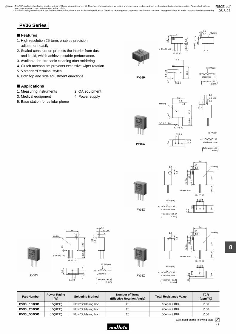
43
8
!Note • Please read rating and !CAUTION (for storage, operating, rating, soldering, mounting and handling) in this catalog to prevent smoking and/or burning, etc.• This catalog has only typical specifications because there is no space for detailed specifications. Therefore, please approve our product specifications or transact the approval sheet for product specifications before ordering.
2.5 2.5
#2
#3#1
(Wiper)
Clockwise
Tolerance : ±0.3in mm
#1 #2
9.6
#3
1.3
1.2
3-0.5±0.1 Dia. 6.0±
1.0
5.0
Marking0.7
1.3
10.02.
55.
20.
5
2.0
Dia
.
0.6
( )PV36P
2.5 2.5
2.5
#1#2#3
9.6
1.3
10.0
0.5
3-0.5±0.1 Dia. 6.0±
1.0
2.0 Dia.
0.6
1.2
1.30.7
Marking
5.0
#2
#3#1
(Wiper)
Clockwise
Tolerance : ±0.3in mm( )
PV36W
#1#2#3
1.3
5.0
9.6
10.0
0.5
2.0
Dia
. 0.6
1.3
0.7
3-0.5±0.1 Dia. 6.0±
1.0
2.5 2.5
2.5
1.2 Marking
#2
#3#1
(Wiper)
Clockwise
Tolerance : ±0.3in mm( )
PV36X
#2
#3#1
(Wiper)
Clockwise
2.5 2.5
2.5
1.2
#1#2#3
9.6
10.0
0.5
3-0.5±0.1 Dia.
6.0±
1.0
2.0 Dia.
0.6
1.30.7
1.2
Marking
5.0
1.3
Tolerance : ±0.3in mm( )
PV36Y
1.3
9.6
2.0
Dia
. 0.6
1.3
0.71.2 Marking
10.0
0.5
6.0±
1.0
#1#2#3
3-0.5±0.1 Dia.
2.5 2.5
Clockwise 5.0
2.5
1.2
#2
#3#1
(Wiper)
Tolerance : ±0.3in mm( )
PV36Z
Part NumberPower Rating
(W)Soldering Method
Number of Turns(Effective Rotation Angle)
Total Resistance ValueTCR
(ppm/°C)
PV36p100C01 0.5(70°C) Flow/Soldering Iron 25 10ohm ±10% ±150
PV36p200C01 0.5(70°C) Flow/Soldering Iron 25 20ohm ±10% ±150
PV36p500C01 0.5(70°C) Flow/Soldering Iron 25 50ohm ±10% ±150
Continued on the following page.
Features1. High resolution 25-turns enables precision adjustment easily. 2. Sealed construction protects the interior from dust and liquid, which achieves stable performance.3. Available for ultrasonic cleaning after soldering4. Clutch mechanism prevents excessive wiper rotation.5. 5 standard terminal styles6. Both top and side adjustment directions.
Applications1. Measuring instruments 2. OA equipment3. Medical equipment 4. Power supply5. Base station for cellular phone
PV36 Series
• This PDF catalog is downloaded from the website of Murata Manufacturing co., ltd. Therefore, it’s specifications are subject to change or our products in it may be discontinued without advance notice. Please check with our sales representatives or product engineers before ordering.
• This PDF catalog has only typical specifications because there is no space for detailed specifications. Therefore, please approve our product specifications or transact the approval sheet for product specifications before ordering.
!Note R50E.pdf08.8.26
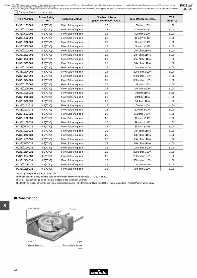
44
8
!Note • Please read rating and !CAUTION (for storage, operating, rating, soldering, mounting and handling) in this catalog to prevent smoking and/or burning, etc.• This catalog has only typical specifications because there is no space for detailed specifications. Therefore, please approve our product specifications or transact the approval sheet for product specifications before ordering.
Part NumberPower Rating
(W)Soldering Method
Number of Turns(Effective Rotation Angle)
Total Resistance ValueTCR
(ppm/°C)
Continued from the preceding page.
PV36p101C01 0.5(70°C) Flow/Soldering Iron 25 100ohm ±10% ±150
PV36p201C01 0.5(70°C) Flow/Soldering Iron 25 200ohm ±10% ±100
PV36p501C01 0.5(70°C) Flow/Soldering Iron 25 500ohm ±10% ±100
PV36p102C01 0.5(70°C) Flow/Soldering Iron 25 1k ohm ±10% ±100
PV36p202C01 0.5(70°C) Flow/Soldering Iron 25 2k ohm ±10% ±100
PV36p502C01 0.5(70°C) Flow/Soldering Iron 25 5k ohm ±10% ±100
PV36p103C01 0.5(70°C) Flow/Soldering Iron 25 10k ohm ±10% ±100
PV36p203C01 0.5(70°C) Flow/Soldering Iron 25 20k ohm ±10% ±100
PV36p253C01 0.5(70°C) Flow/Soldering Iron 25 25k ohm ±10% ±100
PV36p503C01 0.5(70°C) Flow/Soldering Iron 25 50k ohm ±10% ±100
PV36p104C01 0.5(70°C) Flow/Soldering Iron 25 100k ohm ±10% ±100
PV36p204C01 0.5(70°C) Flow/Soldering Iron 25 200k ohm ±10% ±100
PV36p254C01 0.5(70°C) Flow/Soldering Iron 25 250k ohm ±10% ±100
PV36p504C01 0.5(70°C) Flow/Soldering Iron 25 500k ohm ±10% ±100
PV36p105C01 0.5(70°C) Flow/Soldering Iron 25 1M ohm ±10% ±100
PV36p205C01 0.5(70°C) Flow/Soldering Iron 25 2M ohm ±10% ±100
PV36p100C31 0.5(70°C) Flow/Soldering Iron 25 10ohm ±10% ±150
PV36p200C31 0.5(70°C) Flow/Soldering Iron 25 20ohm ±10% ±150
PV36p500C31 0.5(70°C) Flow/Soldering Iron 25 50ohm ±10% ±150
PV36p101C31 0.5(70°C) Flow/Soldering Iron 25 100ohm ±10% ±150
PV36p201C31 0.5(70°C) Flow/Soldering Iron 25 200ohm ±10% ±100
PV36p501C31 0.5(70°C) Flow/Soldering Iron 25 500ohm ±10% ±100
PV36p102C31 0.5(70°C) Flow/Soldering Iron 25 1k ohm ±10% ±100
PV36p202C31 0.5(70°C) Flow/Soldering Iron 25 2k ohm ±10% ±100
PV36p502C31 0.5(70°C) Flow/Soldering Iron 25 5k ohm ±10% ±100
PV36p103C31 0.5(70°C) Flow/Soldering Iron 25 10k ohm ±10% ±100
PV36p203C31 0.5(70°C) Flow/Soldering Iron 25 20k ohm ±10% ±100
PV36p253C31 0.5(70°C) Flow/Soldering Iron 25 25k ohm ±10% ±100
PV36p503C31 0.5(70°C) Flow/Soldering Iron 25 50k ohm ±10% ±100
PV36p104C31 0.5(70°C) Flow/Soldering Iron 25 100k ohm ±10% ±100
PV36p204C31 0.5(70°C) Flow/Soldering Iron 25 200k ohm ±10% ±100
PV36p254C31 0.5(70°C) Flow/Soldering Iron 25 250k ohm ±10% ±100
PV36p504C31 0.5(70°C) Flow/Soldering Iron 25 500k ohm ±10% ±100
PV36p105C31 0.5(70°C) Flow/Soldering Iron 25 1M ohm ±10% ±100
PV36p205C31 0.5(70°C) Flow/Soldering Iron 25 2M ohm ±10% ±100
Operating Temperature Range: -55 to 125 °CThe blank column is filled with the code of adjustment direction and lead type (P, X, Y, W and Z).
The order quantity should be an integral multiple of the "Minimum Quantity".
The last three digits express the individual specification codes. C01 for standard type and C31 for radial taping type (PV36W/PV36X series only).
Construction
Adjustment Screw
Case
Alumina Substrate
Terminal
Wiper
Cermet Resistive Element
Gear
• This PDF catalog is downloaded from the website of Murata Manufacturing co., ltd. Therefore, it’s specifications are subject to change or our products in it may be discontinued without advance notice. Please check with our sales representatives or product engineers before ordering.
• This PDF catalog has only typical specifications because there is no space for detailed specifications. Therefore, please approve our product specifications or transact the approval sheet for product specifications before ordering.
!Note R50E.pdf08.8.26

45
8
!Note • Please read rating and !CAUTION (for storage, operating, rating, soldering, mounting and handling) in this catalog to prevent smoking and/or burning, etc.• This catalog has only typical specifications because there is no space for detailed specifications. Therefore, please approve our product specifications or transact the approval sheet for product specifications before ordering.
Standard Mounting Holes
PV36P
2.5 2.5
2.5
3-0.9
(2)
(3)
(1)
Tolerance: ±0.1in mm
PV36W/X
2.5
3-0.9
2.5
(2)(3) (1)
Tolerance: ±0.1in mm
PV36Y/Z
(3)
(1)
(2)
2.53-0.9
2.5
2.5
Tolerance: ±0.1in mm
Characteristics∆TR : ±2%∆V.S.S.: ±1%
∆TR : ±2%IR : 100M ohm min.
∆TR : ±1%∆V.S.S.: ±1%
∆TR : ±1%∆V.S.S.: ±1%
∆TR : ±3%∆V.S.S.: ±1%
∆TR : ±2%∆V.S.S.: ±1%
∆TR : ±3%∆V.S.S.: ±1%
∆TR : RV1k ohm, RU500k ohm ... ±5%1k ohmFRF500k ohm ... ±3% (200 cycles)
Temperature Cycle
Humidity
Vibration (20G)
Shock (100G)
Temperature Load Life
Low Temperature Exposure
High Temperature Exposure
Rotational Life
∆TR : Total Resistance Change
∆V.S.S.: Voltage Setting Stability
IR : Insulation Resistance
R : Standard Total Resistance
• This PDF catalog is downloaded from the website of Murata Manufacturing co., ltd. Therefore, it’s specifications are subject to change or our products in it may be discontinued without advance notice. Please check with our sales representatives or product engineers before ordering.
• This PDF catalog has only typical specifications because there is no space for detailed specifications. Therefore, please approve our product specifications or transact the approval sheet for product specifications before ordering.
!Note R50E.pdf08.8.26
PV12/PV37/PV36 Series Notice
46
8
!Note • Please read rating and !CAUTION (for storage, operating, rating, soldering, mounting and handling) in this catalog to prevent smoking and/or burning, etc.• This catalog has only typical specifications because there is no space for detailed specifications. Therefore, please approve our product specifications or transact the approval sheet for product specifications before ordering.
Notice (Operating and Storage Conditions)
Notice (Rating)1. When using with partial load (rheostat), minimize the power depending on the resistance value.2. The maximum input voltage to a trimmer potentiometer should not exceed (P•R)^1/2 or the maximum operating voltage, whichever is smaller.
Notice (Soldering and Mounting)1. Soldering (1) Soldering condition Refer to the temperature profile. If the soldering conditions are not suitable, e.g., excessive time and/or excessive temperature, the trimmer potentiometer may deviate from the specified characteristics. (2) To minimize mechanical stress when adjusting, the trimmer potentiometer should be mounted onto PCB without gap. (3) The soldering iron should not come in contact with the case of the trimmer potentiometer. If such contact does occur, the trimmer potentiometer may be damaged.
2. Mounting (1) Use PCB hole to meet the pin of the trimmer potentiometer. If the trimmer potentiometer installs into insufficient PCB hole, the trimmer potentimeter may be damaged by mechanical stress. (2) Do not apply excessive force, preferably 9.8N max. (Ref. 1kgf) when the trimmer potentiometer is mounted to the PCB.3. Cleaning Isopropyl-alcohol and Ethyl-alcohol are applicable solvents for cleaning. If you use any other types of solvents, please consult with a Murata factory representative prior to using.
1. Store in temperatures of -10 to +40 deg. C and relative humidity of 30-85%.2. Do not store in or near corrosive gases.3. Use within six months after delivery. 4. Open the package just before using.5. Do not store under direct sunlight.6. If you use the trimmer potentiometer in an environment other than listed below, please consult with a Murata factory representative prior to using. The trimmer potentiometer should not be used under the following environmental conditions:
(1) Corrosive gaseous atmosphere (Ex. Chlorine gas, Hydrogen sulfide gas, Ammonia gas, Sulfuric acid gas, Nitric oxide gas, etc.) (2) In liquid (Ex. Oil, Medical liquid, Organic solvent, etc.) (3) Dusty/dirty atmosphere (4) Direct sunlight (5) Static voltage nor electric/magnetic fields (6) Direct sea breeze (7) Other variations of the above
• This PDF catalog is downloaded from the website of Murata Manufacturing co., ltd. Therefore, it’s specifications are subject to change or our products in it may be discontinued without advance notice. Please check with our sales representatives or product engineers before ordering.
• This PDF catalog has only typical specifications because there is no space for detailed specifications. Therefore, please approve our product specifications or transact the approval sheet for product specifications before ordering.
!Note R50E.pdf08.8.26

PV12/PV37/PV36 Series Notice
47
8
!Note • Please read rating and !CAUTION (for storage, operating, rating, soldering, mounting and handling) in this catalog to prevent smoking and/or burning, etc.• This catalog has only typical specifications because there is no space for detailed specifications. Therefore, please approve our product specifications or transact the approval sheet for product specifications before ordering.
Soldering Profile Flow Soldering ProfileSoldering profile for Lead-free solder (96.5Sn/3.0Ag/0.5Cu), Eutectic solder (63Sn/37Pb)
Tem
pera
ture
(°C
)
t1
t2
T3T2
T1
Time (s)
Limit Profile
Standard Profile
Heating
Pre-heating
Standard Profile
Pre-heating Heating
Temp. (T1)
°C
Time (t1)
sec.
Temp. (T2)
°C
Time (t2)
sec.
150 60 to 120 250 5 max. 1
Cycleof Flow
Time
Limit Profile
Pre-heating Heating
Temp. (T1)
°C
Time (t1)
sec.
Temp. (T3)
°C
Time (t2)
sec.
150 60 to 120 260 3 max. 1
Cycleof Flow
Time
Standard Condition
Temperature of Soldering Iron Tip
°C
Soldering Time
sec.
Soldering Iron Power Output
W
350±10 3 max. 30 max. 1
Cycle of Soldering Iron
Time
Soldering Iron
Series
PV12PV37PV36
Series
PV12PV37PV36
Notice (Handling)
Notice (Other)1. Please make sure that your product has been evaluated and confirmed against your specifications when our product is mounted to your product.2. Murata cannot guarantee trimmer potentiometer integrity when used under conditions other than those specified in this document.
1. Use suitable screwdrivers that fit comfortably in driver slot. We recommend the screwdrivers below. * Recommended screwdriver for manual adjustment ENGINEER INC.: DA-40 (Murata P/N: KMDR180) We can supply the screwdrivers above. If you place order, please specify the Murata P/N.2. Do not apply more than 9.8N (Ref. 1kgf) of twist and stress after mounting onto PCB to prevent contact intermittence. If excessive force is applied, the trimmer potentiometer may not function.
3. When adjusting with an adjustment tool, the applied force to the adjustment screw should not exceed 4.9N (Ref. 500gf). If excessive force is applied, the trimmer potentiometer may not function due to damage.4. When using a lock paint to fix slot position, please use adhesive resin without chlorine or sulfur (Three-bond "1401 series") and evaluate performance with your product. Lock paint may cause corroison or electrical contact problems.
• This PDF catalog is downloaded from the website of Murata Manufacturing co., ltd. Therefore, it’s specifications are subject to change or our products in it may be discontinued without advance notice. Please check with our sales representatives or product engineers before ordering.
• This PDF catalog has only typical specifications because there is no space for detailed specifications. Therefore, please approve our product specifications or transact the approval sheet for product specifications before ordering.
!Note R50E.pdf08.8.26

No. Item Test Methods
Specifications and Test Methods
Residual Resistance1
Position the contact arm at the extreme counterclockwise limit of mechanical travel and measure the resistancebetween the contact arm and the corresponding end terminal. Then, position the contact arm at the extreme clock-wise limit of mechanical travel and measure the resistance between the contact arm and the corresponding end ter-minal. During this test, take suitable precautions to ensure that the rated current of the resistance element is notexceeded.
Contact Resistance2
3
1
Rx#1
#2
#3
ProofreadResistence AC
Amplifier
Oscilloscope
Rx : Trimmer PotentiometerOscilloscope bandwidth: 100Hz to 50kHz
Constant CurrentSource (Test current shown in Table 2)
Figure 1: CRV measuring circuit
Contact resistance variation should be measured with the measuring circuit shown below, or its equivalent. Theoperating wiper should be rotated in both directions through 90% of the actual effective-electrical travel for a total of6 cycles.The rate of rotation of the operating wiper should be such that the wiper completes 1 count in determining whether ornot a contact resistance variation is observed at least twice in the same location. The test current should follow thevalue given in Table 2 unless otherwise limited by the power rating.
Standard TotalResistance R (ohm)
100VRF10k10kVRF100k
100kVR
20mA max.
Test Current
Table 2: Test current for CRV
1mA max.100µA max.
Humidity ExposureThe wiper contact point should be preset at about 50% position of effective rotational angle. After that, the poten-tiometer should be placed in a chamber at 40±2°C and 90 - 95% without loading for 500±12 hours.The resistance value should be measured after keeping the potentiometer in a room for 5±1/6 hours.
4High TemperatureExposure
The wiper contact point should be preset at about 50% position of effective rotational angle. After that, the poten-tiometer should be placed in a chamber at 70±2°C without loading for 500±12 hours. The resistance value should bemeasured after keeping the potentiometer in a room for 1.5±1/6 hours.
5 Humidity Load Life
The wiper contact point should be preset at about 50% position of effective rotational angle. After that, the poten-tiometer should be placed in a chamber at 40±2°C and 90 - 95% with loading the 1/2 rated voltage between #1 and#2 terminals, intermittently 1.5 hours ON and 0.5 hours OFF for 1000±12 hours. The resistance value should be measured after keeping the potentiometer in a room for 5±1/6 hours.
6 Load Life
The wiper contact point should be preset at about 50% position of effective rotational angle. After that, the poten-tiometer should be placed in a chamber at 70±2°C (50±2°C for PVZ) with loading the 1/2 rated voltage between #1and #2 terminals, intermittently 1.5 hours ON and 0.5 hours OFF for 1000±12 hours. The resistance value should bemeasured after keeping the potentiometer in a room for 1 to 2 hours.
The tests and measurements should be conducted under the condition of 15 to 35°C of temperature, 25 to 75% of relative humidity and 86 to 106 kpa ofatmospheric pressure unless otherwise specified. If questionable results occur that have been measured in accordance with the above mentioned conditions, the tests and measurements should be conducted under the condition of 25±2°C of temperature, 45 to 55% of relative humidity and 86 to106 kpa of atmospheric pressure.
7 Temperature Cycle
The wiper contact point should be preset at about 50% position of effective rotational angle. After that, the poten-tiometer should be subjected to Table 3, Table 4 temperature for 5 cycles. The resistance value should be measuredafter keeping the potentiometer in a room for 1 to 2 hours.
SequenceTemp. (°C) -25±3
1
Table 3: PVZ
Time (min.)+25±2
2 3+85±3 +25±2
4
30±3 10 max.
SequenceTemp. (°C) -55±3
1
Table 4: PVA2/PVM4A---C01
Time (min.) 30±3+25±2
2
10 max.
3+125±3 +25±2
4
30±3 10 max.10 max.30±3
The trimmer potentiometer should be subjected to each of the following temperatures (see Table 5, Table 6) for 30to 40 minutes. The resistance value should be measured in the chamber.
TCR= Z 106 (ppm/°C)
T1 : Reference temperature in degrees celsiusT2 : Test temperature in degrees celsiusR1 : Resistance at reference temperature in ohmR2 : Resistance at test temperature in ohm
R2 – R1
R1 (T2 – T1)
The wiper should be rotated over 90% of the effective rotational angle without loading at a speed of 10 cycles perminute, for 10 cycles continuously. The resistance value should be measured after keeping the potentiometer in aroom for 10±5 minutes.
SequenceTemp. (°C) +25±2
1*
Table 5: PVZ
-25±32 3*
+25±2 +85±34
Temperature Coefficient ofResistance
Rotational Life
8
9
SequenceTemp. (°C) +25±2
1*
Table 6: PVA2/PVM4A---C01
-55±32 3*
+25±2 +125±34
Note*: Norm temp.
48
8
!Note • Please read rating and !CAUTION (for storage, operating, rating, soldering, mounting and handling) in this catalog to prevent smoking and/or burning, etc.• This catalog has only typical specifications because there is no space for detailed specifications. Therefore, please approve our product specifications or transact the approval sheet for product specifications before ordering.
SMD Open Type (PVZ2/A2/Z3)/SMD Sealed Type (PVM4A_C01 Series) Specifications and Test Methods
• This PDF catalog is downloaded from the website of Murata Manufacturing co., ltd. Therefore, it’s specifications are subject to change or our products in it may be discontinued without advance notice. Please check with our sales representatives or product engineers before ordering.
• This PDF catalog has only typical specifications because there is no space for detailed specifications. Therefore, please approve our product specifications or transact the approval sheet for product specifications before ordering.
!Note R50E.pdf08.8.26
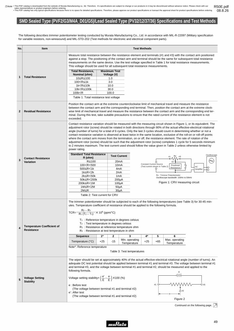
No. Item Test Methods
Total Resistance1
Measure total resistance between the resistance element and terminals (#1 and #3) with the contact arm positionedagainst a stop. The positioning of the contact arm and terminal should be the same for subsequent total resistancemeasurements on the same device. Use the test voltage specified in Table 1 for total resistance measurements.This voltage should be used for all subsequent total resistance measurements.
Specifications and Test Methods
Residual Resistance2
Position the contact arm at the extreme counterclockwise limit of mechanical travel and measure the resistancebetween the contact arm and the corresponding end terminal. Then, position the contact arm at the extreme clock-wise limit of mechanical travel and measure the resistance between the contact arm and the corresponding end ter-minal. During this test, take suitable precautions to ensure that the rated current of the resistance element is notexceeded.
Contact ResistanceVariation
3
4
1
5
Rx#1
#2
#3
Constant Current Source(Test current shown in Table 2)
ProofreadResistance AC
Amplifier
Oscilloscope
Oscilloscope bandwidth :100Hz to 50kHzRx : Trimmer Potentiometer
Figure 1: CRV measuring circuit
Contact resistance variation should be measured with the measuring circuit shown in Figure 1, or its equivalent. Theadjustment rotor (screw) should be rotated in both directions through 90% of the actual effective-electrical rotationalangle (number of turns) for a total of 6 cycles. Only the last 3 cycles should count in determining whether or not acontact resistance variation is observed at least twice in the same location, exclusive of the roll-on or roll-off pointswhere the contact arm moves from the termination, on or off, the resistance element. The rate of rotation of theadjustment rotor (screw) should be such that the adjustment rotor (screw) completes 1 cycle for 5 seconds minimumto 2 minutes maximum. The test current used should follow the value given in Table 2 unless otherwise limited bypower rating.
Standard Total ResistanceR (ohm)
RV100100FRF500500VRF1k
1kVRF2k2kVRF50k
50kVRF200k200kVRF1M
1MVRF2M2MVR
20mA
Test Current
Table 2: Test current for CRV
10mA4mA
Temperature Coefficient ofResistance
The trimmer potentiometer should be subjected to each of the following temperatures (see Table 3) for 30-45 min-utes. Temperature coefficient of resistance should be applied to the following formula.
TCR= Z 106 (ppm/°C)
T1 : Reference temperature in degrees celsiusT2 : Test temperature in degrees celsiusR1 : Resistance at reference temperature ohmR2 : Resistance at test temperature in ohm
R2 – R1
R1 (T2 – T1)
Voltage SettingStability
The wiper should be set at approximately 40% of the actual effective-electrical rotational angle (number of turns). Anadequate DC test potential should be applied between terminal #1 and terminal #3. The voltage between terminal #1and terminal #3, and the voltage between terminal #1 and terminal #2, should be measured and applied to the following formula.
Voltage setting stability= ( – ) Z100 (%)
e : Before test(The voltage between terminal #1 and terminal #2)
e': After test(The voltage between terminal #1 and terminal #2)
eE
e'E
The following describes trimmer potentiometer testing conducted by Murata Manufacturing Co., Ltd. in accordance with MIL-R-22097 (Military specificationfor variable resistors, non-wirewound) and MIL-STD-202 (Test methods for electronic and electrical component parts).
2mA1mA
200µA100µA50µA30µA
e
#2
#1 #3
E
Figure 2
Total Resistance,Nominal (ohm)
10VRV100100FRV1k
1kFRV10k10kFRV100k
100kFR
1.0
Maximum TestVoltage (V)
Table 1: Total resistance test voltage
3.010.030.0
100.0
Sequence
Temperature (°C) +25
1*
Table 3: Test temperatures
-15
2 3Min. operatingTemperature
+25
4*
Note*: Reference temperature
+65
5 6Max. operatingTemperature
Continued on the following page.
49
8
!Note • Please read rating and !CAUTION (for storage, operating, rating, soldering, mounting and handling) in this catalog to prevent smoking and/or burning, etc.• This catalog has only typical specifications because there is no space for detailed specifications. Therefore, please approve our product specifications or transact the approval sheet for product specifications before ordering.
SMD Sealed Type (PVF2/G3/M4A_D01/G5)/Lead Sealed Type (PV32/12/37/36) Specifications and Test Methods
• This PDF catalog is downloaded from the website of Murata Manufacturing co., ltd. Therefore, it’s specifications are subject to change or our products in it may be discontinued without advance notice. Please check with our sales representatives or product engineers before ordering.
• This PDF catalog has only typical specifications because there is no space for detailed specifications. Therefore, please approve our product specifications or transact the approval sheet for product specifications before ordering.
!Note R50E.pdf08.8.26

No. Item Test Methods
Temperature Cycle6
The trimmer potentiometer should be subjected to Table 4 temperature for 5 cycles. The trimmer potentiometershould be removed from the chamber, and maintained at a temperature of 25±5°C for 1-2 hours.
Specifications and Test Methods
Humidity7
1) PV12, PV32, PVM4A---D01 series The trimmer potentiometer should be placed in a chamber at a temperature of 40±2°C and a humidity of 90-95%without loading for 250±8 hours (500±12 hours for PVM4A---D01 series). The trimmer potentiometer should beremoved from the chamber, and maintained at a temperature of 25±5°C for 5±1/6 hours.2) PVF2 seriesThe trimmer potentiometer should be placed in a chamber at 60±2°C and 90-95% without loading for 1000±12hours. The trimmer potentiometer should be removed from the chamber, and maintained at a temperature of 25±5°Cfor 5±1/6 hours 2) PVG3, PVG5, PV36, PV37 seriesThe trimmer potentiometer should be subjected to the programmed humidity environment for 10cycle (see Figure 3).The trimmer potentiometer should be removed from the chamber, and maintained at a temperature of 25±5°C for1.5±1/2 hours.
1
Vibration8
1) PV-- seriesThe trimmer potentiometer should be vibrated throughout the frequency range at the 20G level. A complete frequen-cy range, 10Hz to 2000Hz and back, should be made within 15 minutes for a total of 4 sweeps in each of the threeaxis directions for a total of 12 sweeps.2) PVF2 seriesThe trimmer potentiometer should be subjected to vibration at 0.3 inch amplitude. The frequency should be varieduniformly between the approximate limits of 10Hz and 55Hz. This motion should be applied for period of 2 hours ineach of 3 mutually perpendicular directions (total of 6 hours).
SequenceTemp.(°C)
PV-- seriesPVF2 series
1
Table 4: One cycle of temperature cycle.
-55±3-25±3
2
+25±2
Time (min.) 30 5 max.
3+125±3+60±3
30
4
+25±2
5 max.
Continued from the preceding page.
INITIAL CONDITIONINGIN A DRY OVEN
24 HOURS
INITIAL MEASUREMENTSAS SPECIFIED IN 3.2
CIRCULATION OF CONDITIONING AIR SHOULDBE AT A MINIMUM CUBIC RATE PER MINUTEEQUIVALENT TO 5 TIMES THE VOLUME OFTHE CHAMBER
22 23 242120191817161514131211109876543210
70
65
60
55
50
45
40
35
30
25
20
15
10
5
-5
-10
0
ONE CYCLE 24 HOURS. REPEAT AS SPECIFIED IN 3.3
PRIOR TO FIRST CYCLEUNLESS OTHERWISESPECIFIED
STEP 7STEP 6STEP 5STEP 4STEP 3STEP 2STEP 1
UNLESS OTHERWISE SPECIFIEDTEMPERATURE TOLERANCE IS,±2°C AT ALL POINTS WITHIN THECHAMBER EXCEPT THE IMMEDIATEVICINITY OF THE SPECIMENS ANDTHE CHAMBER SURFACES
STEP 7a
STEPS 7a AND 7b PERFORMED DURING ANY5 OF THE FIRST 9 CYCLES. HUMIDITYUNCONTROLLED DURING STEPS 7a AND 7bONLY
VOLTAGE APPLIED AS SPECIFIED IN 3.5
STEP 7b
END OF FINAL CYCLEMEASUREMENTS ASSPECIFIED IN 3.6
+10°C-2°C
HUMIDITYUNCONTROLLED
RATE OF CHANGE OF TEMPERATURE IS UNSPECIFIED.HOWEVER, SPECIMENS SHOULD NOT BE SUBJECTED TO RADIANT HEAT FROM CHAMBER-CONDITIONINGPROCESSES
90-98%RH
80-98%RH
90-98%RH
80-98%RH
90-98%RH
TE
MP
ER
AT
UR
E (
DE
GR
EE
S C
ELS
IUS
)
MIL-STD-202 METHOD 106
Figure 3
Shock9
1) PV-- seriesThe trimmer potentiometer should be shocked at the 100G level and should be subjected to 4 shocks in each of thethree axis directions for a total of 12 shocks.2) PVM4A---D01 seriesThe trimmer potentiometer should be shocked at the 100G level and should be subjected to 3 shocks in each of thesix axis directions for a total of 18 shocks.
Temperature Road Life10
Full rated continuous working voltage not exceeding the maximum rated voltage should be applied intermittentlybetween terminal #1 and terminal #3 of the trimmer potentiometer, 1.5 hours on and 0.5 hours off, for a total of1000±12 hours, at a temperature of 70±2°C (85±2°C for PV37 series, 50±2°C for PVF2 series). The trimmer potentiometer should be removed from the chamber, and maintained at a temperature of 25±5°C for 1 to 2 hours.
High Temperature Exposure(Except for PVF2)
11The trimmer potentiometer should be placed in a chamber at a temperature of 125±3°C 250±8 hours without load-ing. The trimmer potentiometer should be removed from the chamber, and maintained at a temperature of 25±5°Cfor 1 to 2 hours.
Low Temperature Exposure(Except for PVF2 andPVM4A---D01)
12
The trimmer potentiometer should be placed in a chamber at a temperature of -55±3°C for 1 hours without loading.Full rated continuous working voltage not exceeding the maximum rated voltage should be applied for 45 minutes.The trimmer potentiometer should be removed from the chamber, and maintained at a temperature of 25±5°C forapproximately 24 hours.
Continued on the following page.
50
8
!Note • Please read rating and !CAUTION (for storage, operating, rating, soldering, mounting and handling) in this catalog to prevent smoking and/or burning, etc.• This catalog has only typical specifications because there is no space for detailed specifications. Therefore, please approve our product specifications or transact the approval sheet for product specifications before ordering.
SMD Sealed Type (PVF2/G3/M4A_D01/G5)/Lead Sealed Type (PV32/12/37/36) Specifications and Test Methods
• This PDF catalog is downloaded from the website of Murata Manufacturing co., ltd. Therefore, it’s specifications are subject to change or our products in it may be discontinued without advance notice. Please check with our sales representatives or product engineers before ordering.
• This PDF catalog has only typical specifications because there is no space for detailed specifications. Therefore, please approve our product specifications or transact the approval sheet for product specifications before ordering.
!Note R50E.pdf08.8.26

Specifications and Test Methods
Resistor 1End Terminal End Terminal Resistor 2 End TerminalEnd Terminal
DC supply
Figure 4
No. Item Test Methods
Low Temperature Operation(Only for PVF2 andPVM4A---D01)
13The trimmer potentiometer should be placed in a chamber at a temperature of -25±3°C (-55±3°C for PVM4A---D01 series) 48±4 hours without loading. The trimmer potentiometer should be removed from the chamber, and main-tained at a temperature of 25±5°C for 1-2 hours.
Continued from the preceding page.
Rotational Life14
1)PV-- seriesFull rated continuous working voltage not exceeding the maximum rated voltage should be applied with the circuitshown in the figure. The adjustment rotor (screw) should be continuously cycled through not less than 90% of effec-tive-electrical rotational angle (number of turns), at the rate of 1 cycle for 5 seconds minimum to 2.5 minutes maxi-mum for total of 200 cycles.
2) PVG3, PVG5 seriesThe adjustment rotor (screw) should be continuously cycled though not less than 90% of effective-electrical rotation-al angle (number of turns), at the rate of 1 cycle for 5 seconds minimum to 2.5 minutes maximum for a total of 50(100 for PVG5) cycles, without loading.
3) PVF2, PVM4A---D01 seriesThe wiper should be rotated over 90% of the effective rotational angle without loading at a speed of 10 cycles perminute, for 100 cycles continuously.
51
8
!Note • Please read rating and !CAUTION (for storage, operating, rating, soldering, mounting and handling) in this catalog to prevent smoking and/or burning, etc.• This catalog has only typical specifications because there is no space for detailed specifications. Therefore, please approve our product specifications or transact the approval sheet for product specifications before ordering.
SMD Sealed Type (PVF2/G3/M4A_D01/G5)/Lead Sealed Type (PV32/12/37/36) Specifications and Test Methods
• This PDF catalog is downloaded from the website of Murata Manufacturing co., ltd. Therefore, it’s specifications are subject to change or our products in it may be discontinued without advance notice. Please check with our sales representatives or product engineers before ordering.
• This PDF catalog has only typical specifications because there is no space for detailed specifications. Therefore, please approve our product specifications or transact the approval sheet for product specifications before ordering.
!Note R50E.pdf08.8.26

Packaging
52
8
!Note • Please read rating and !CAUTION (for storage, operating, rating, soldering, mounting and handling) in this catalog to prevent smoking and/or burning, etc.• This catalog has only typical specifications because there is no space for detailed specifications. Therefore, please approve our product specifications or transact the approval sheet for product specifications before ordering.
Minimum Quantity
Part NumberMinimum Quantity (pcs.)
PVZ2A
PVZ2R
PVA2
PVZ3A
PVZ3G
PVZ3K
PVG3A/G
PVG3K
PVM4
PVF2A
PVG5A
PVG5H
PV32
PV12
PV36W
PV36Y
PV36X
PV36Z/P
PV37Y/Z
PV37W/X/P
3000
3000
3000
2000
2500
1500
1000
500
500
500
250
500
—
—
—
—
—
—
—
—
ø180mm reel
12000
—
—
8000
—
—
—
—
3000
—
—
—
—
—
—
—
—
—
—
—
ø330mm reel
—
—
—
—
—
—
—
—
—
—
—
—
—
—
1000
—
1000
—
1000
—
Ammo Pack
—
—
—
—
—
—
—
—
—
—
—
—
—
—
1000
1000
800
800
—
—
Magazine
1000
1000
1000
1000
1000
1000
500
—
500
100
100
100
300
50
100
100
100
100
100
100
Bulk
—
—
—
—
—
—
—
—
—
—
—
—
—
—
—
—
—
—
—
—
Tray
Dimensions of Reel
PVZ2A/PVA2/PVZ3A/PVZ3G/PVF2
(in mm)
13.0±0.5 Dia.
21.0±0.8 Dia.
2.0±0.5
178±2 Dia.
9.0±1.0
50 m
in.
13.0±1.0
PVZ2R/PVZ3K/PVM4/PVG3/PVG5H
(in mm)
13.0±0.5 Dia.
21.0±0.8 Dia.
2.0±0.5
178±2 Dia.
13.0±1.050
min
.17.0±1.0
PVG5A
(in mm)
21.0±0.8 Dia.
50 D
ia. m
in.
178.0±2.0 Dia.
13.0±0.5 Dia.
2.0±0.5
17.0±1.0
19.4±1.0
Continued on the following page.
• This PDF catalog is downloaded from the website of Murata Manufacturing co., ltd. Therefore, it’s specifications are subject to change or our products in it may be discontinued without advance notice. Please check with our sales representatives or product engineers before ordering.
• This PDF catalog has only typical specifications because there is no space for detailed specifications. Therefore, please approve our product specifications or transact the approval sheet for product specifications before ordering.
!Note R50E.pdf08.8.26

Packaging
53
8
!Note • Please read rating and !CAUTION (for storage, operating, rating, soldering, mounting and handling) in this catalog to prevent smoking and/or burning, etc.• This catalog has only typical specifications because there is no space for detailed specifications. Therefore, please approve our product specifications or transact the approval sheet for product specifications before ordering.
Continued from the preceding page.
Dimensions of Plastic Tape
Part Number
PVZ2A
PVZ2R
PVA2
PVZ3A
PVZ3G
PVZ3K
PVF2
2.4±0.2
3.3±0.2
2.3±0.2
(in mm)
A
3.1±0.1
5.1±0.2
3.1±0.1
3.8±0.2
5.8±0.2
2.3±0.2
B
8.0±0.2
12.0±0.2
8.0±0.2
12.0±0.2
8.0±0.2
C
3.5±0.1
5.5±0.1
3.5±0.1
5.5±0.1
3.5±0.1
D
1.1±0.1
1.0±0.1
1.1±0.1
1.95±0.1
1.3±0.1
2.3±0.1
2.3±0.1
I
0.2±0.1
0.3±0.1
0.2±0.1
0.3±0.1
J
a
a'
4.0±0.1
2.0±0.1
4.0±0.11.5 Dia.+0.1
–0
1.75±0.1
D C
A
B
J
I
Across a – a'
Tape feeding direction
• The side containing terminals #1 and #3 faces the plastic tape pilot holes.
PVZ2 / PVA2 / PVZ3 / PVF2
Part Number
PVG3A
PVG3G
PVM4
PVG5H
4.0±0.1
4.5±0.2
5.4±0.2
A
4.0±0.1
4.9±0.1
5.5±0.2
5.8±0.2
B
2.1±0.1
2.15±0.1
4.0±0.1
I
0.3±0.1
0.3±0.1
0.4±0.1
J
(in mm)
• The side containing terminals #1 and #3 faces the plastic tape pilot holes
(except PVG3).
PVG3A / PVG3G / PVM4 / PVG5H
J
I
Across a – a'
12.0
±0.2
5.5±
0.1
1.75
±0.1
2.0±0.1
8.0±0.1a
B
A
Tape feeding direction
a'
4.0±0.1 1.5 Dia.+0.1–0
Continued on the following page.
• This PDF catalog is downloaded from the website of Murata Manufacturing co., ltd. Therefore, it’s specifications are subject to change or our products in it may be discontinued without advance notice. Please check with our sales representatives or product engineers before ordering.
• This PDF catalog has only typical specifications because there is no space for detailed specifications. Therefore, please approve our product specifications or transact the approval sheet for product specifications before ordering.
!Note R50E.pdf08.8.26

Packaging
54
8
!Note • Please read rating and !CAUTION (for storage, operating, rating, soldering, mounting and handling) in this catalog to prevent smoking and/or burning, etc.• This catalog has only typical specifications because there is no space for detailed specifications. Therefore, please approve our product specifications or transact the approval sheet for product specifications before ordering.
Continued from the preceding page.
Dimensions of Plastic Tape
Part Number
PVG5A 4.3±0.2
A
5.4±0.2
B
5.4±0.1
I
0.4±0.1
J
(in mm)
PVG5A
J
I
Across a – a'
16.0
±0.3
7.5±
0.1
1.75
±0.1
Tape feeding direction
2.0±0.1
12.0±0.2a
B
Aa'
4.0±0.1 1.5 Dia.+0.1–0
PVG3K
(in mm)
4.0±0.1
2.8±0.14.0±0.1
2.0±0.1 0.3±0.1
8.0±0.1
1.5 Dia.+0.1-0
12.0
±0.2
6.2±
0.1
5.5±
0.1
1.75
±0.1
0
Tape feeding direction
Across a-a'
a
a'
Dimensions of Radial Taping
PV37Y12.7±1.0
0±2.06.4
6.7
2.5±0.5
12.7±0.36.35±0.70
3−0.4±0.1 Dia
18.0
±0.5
9.0±
0.5
2.5±0.5
0.5±
0.2
Across A-A'
A A'
Tolerance : ±0.3 ( in mm)
18.5
- 0.
5+
1.0
4.0±0.1 Dia.
B B'
#3#2#16.0
min
.
Across B-B'
2.52.5
2.0
4.0
PV37Z12.7±1.0
0±2.06.4
6.7
2.5±0.5
12.7±0.36.35±0.70
3–0.4±0.1 Dia
18.0
±0.5
9.0±
0.5
2.5±0.5
0.5±
0.2
Across A-A'
A A'
Tolerance : ±0.3 ( in mm)
18.5
- 0.
5+
1.0
4.0±0.1 Dia.
B B'
#3#2#16.0
min
.
Across B-B'
2.0
2.52.5
4.0
PV36W
18.5
- 0.
5+
1.0
12.7±1.00±2.09.6
10.0
2.5±0.5
12.7±0.36.35±0.70
3–0.5±0.1 Dia
18.0
±0.5
9.0±
0.5
2.5±0.5
0.5±
0.2
Across A-A'
A A'
Tolerance : ±0.3 ( in mm)
4.0±0.1 Dia.
B B'
#3#2#16.0
min
.
Across B-B' 2.5
2.52.5
Continued on the following page.
• This PDF catalog is downloaded from the website of Murata Manufacturing co., ltd. Therefore, it’s specifications are subject to change or our products in it may be discontinued without advance notice. Please check with our sales representatives or product engineers before ordering.
• This PDF catalog has only typical specifications because there is no space for detailed specifications. Therefore, please approve our product specifications or transact the approval sheet for product specifications before ordering.
!Note R50E.pdf08.8.26

Packaging
55
8
!Note • Please read rating and !CAUTION (for storage, operating, rating, soldering, mounting and handling) in this catalog to prevent smoking and/or burning, etc.• This catalog has only typical specifications because there is no space for detailed specifications. Therefore, please approve our product specifications or transact the approval sheet for product specifications before ordering.
Continued from the preceding page.
Dimensions of Radial Taping
PV36X12.7±1.0
0±2.09.6
10.0
2.5±0.5
12.7±0.36.35±0.70
3–0.5±0.1 Dia
18.0
±0.5
9.0±
0.5
2.5±0.5
0.5±
0.2
Across A-A'
A A'
6.0
min
.
Tolerance : ±0.3 ( in mm)
18.5
- 0.
5+
1.0
4.0±0.1 Dia.
#3 #2 #1
B B'
Across B-B' 2.5
2.52.5
Dimensions of Ammo Pack
3T
1T
330 max.46 max.
305
max
.
(in mm)
Dimensions of Magazine Packaging
(in mm)
7.3±0.5
21.1
±0.5
508 +0–1.0 11.5±0.5
18.0
±0.5
508 +0–1.0
PV36W/Y/X/Z PV36P
• This PDF catalog is downloaded from the website of Murata Manufacturing co., ltd. Therefore, it’s specifications are subject to change or our products in it may be discontinued without advance notice. Please check with our sales representatives or product engineers before ordering.
• This PDF catalog has only typical specifications because there is no space for detailed specifications. Therefore, please approve our product specifications or transact the approval sheet for product specifications before ordering.
!Note R50E.pdf08.8.26
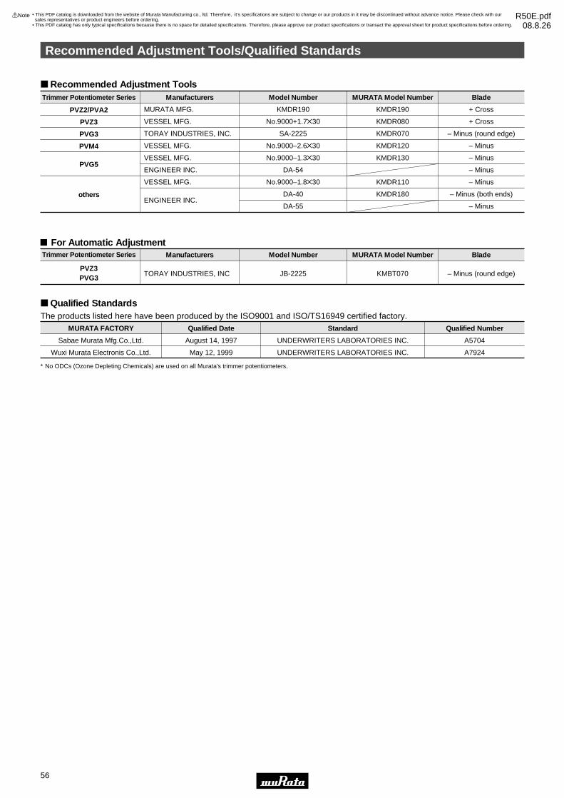
Recommended Adjustment Tools/Qualified Standards
56
8
!Note • Please read rating and !CAUTION (for storage, operating, rating, soldering, mounting and handling) in this catalog to prevent smoking and/or burning, etc.• This catalog has only typical specifications because there is no space for detailed specifications. Therefore, please approve our product specifications or transact the approval sheet for product specifications before ordering.
Recommended Adjustment Tools
PVZ2/PVA2
PVZ3
PVG3
PVM4
PVG5
others
MURATA MFG.
VESSEL MFG.
TORAY INDUSTRIES, INC.
VESSEL MFG.
VESSEL MFG.
ENGINEER INC.
VESSEL MFG.
ENGINEER INC.
ManufacturersTrimmer Potentiometer Series
KMDR190
No.9000+1.7Z30
SA-2225
No.9000–2.6Z30
No.9000–1.3Z30
DA-54
No.9000–1.8Z30
DA-40
DA-55
Model Number
KMDR190
KMDR080
KMDR070
KMDR120
KMDR130
KMDR110
KMDR180
MURATA Model Number
+ Cross
+ Cross
– Minus (round edge)
– Minus
– Minus
– Minus
– Minus
– Minus (both ends)
– Minus
Blade
Trimmer Potentiometer Series
PVZ3PVG3
TORAY INDUSTRIES, INC
Manufacturers
JB-2225
Model Number
KMBT070
MURATA Model Number
– Minus (round edge)
Blade
For Automatic Adjustment
Qualified Standards
MURATA FACTORY
Sabae Murata Mfg.Co.,Ltd.
Qualified Date
August 14, 1997
Standard
UNDERWRITERS LABORATORIES INC.
Qualified Number
A5704
Wuxi Murata Electronis Co.,Ltd. May 12, 1999 UNDERWRITERS LABORATORIES INC. A7924
The products listed here have been produced by the ISO9001 and ISO/TS16949 certified factory.
∗ No ODCs (Ozone Depleting Chemicals) are used on all Murata's trimmer potentiometers.
• This PDF catalog is downloaded from the website of Murata Manufacturing co., ltd. Therefore, it’s specifications are subject to change or our products in it may be discontinued without advance notice. Please check with our sales representatives or product engineers before ordering.
• This PDF catalog has only typical specifications because there is no space for detailed specifications. Therefore, please approve our product specifications or transact the approval sheet for product specifications before ordering.
!Note R50E.pdf08.8.26