triplepack 3.1 - ats diesel v3.1.pdfallison lct-1000/2000/2400 triple-packtm kit installation manual...
TRANSCRIPT
12/11/06
Allison LCT-1000/2000/2400 Triple-PackTM Kit Installation Manual
Version 3.1
PLEASE READ BEFORE INSTALLATION
Items Included with this kit:
1) Five StarTM Viskus Drive Torque Converter 2) C1, C2, C3 Clutch Packs 3) Ring Gear Spacer 4) 6 or 12 mounting bolts (to secure torque converter to flex plate) 5) Installation manual for Triple-PackTM kit 6) Thrust Bearing
The Triple-PackTM kit for the Allison transmission has been designed to correct the failures that are created when power is turned up on the Duramax diesel. The Allison transmission begins to show its weakness in two areas once power is increased over 270 horsepower. The Triple-PackTM is designed to:
• Eliminate 5th gear slip that can cause fail-safe condition, Neutral condition • Eliminate torque converter clutch slip that can cause a check engine light and reduce
power • Better match fluid coupling of the converter to the increased torque output of the engine • Offer much improved torque capacity of the transmission with ATS Clutch packs
In order to replace the factory torque converter with the Five StarTM Viskus Drive Torque Converter, the transmission must be removed from the vehicle. Once the torque converter and transmission have been removed from the vehicle the pump can be accessed. Applying the proper torque to the stator support and the pump housing to the front of the transmission case is a step that must be done to ensure years of trouble free operation.

12/11/06
Figure 1 1) Stand the transmission on its end, Engine side up. It is best to tilt the transmission into
a drain pan; the pan will catch the excessive transmission fluid while the transmission is standing upright.
DO NOT REMOVE BELL HOUSING WITH UNIT LYING ON PAN. Unit MUST be standing up, bell housing up.
a. 4 Wheel Drive: Use a flex plate placed inside the drain pan to support the
transmission, the output shaft protruding out of the backside of the transmission will prevent the transmission from balancing on it’s extension housing. When placing the transmission on the flex plate, the hole in the flex plate will allow the output shaft to protrude through it and the flex plate will support the transmission on the extension housing and allow the transmission to balance, you can remove the bell housing from the transmission with out having to support the transmission case.
b. 2 Wheel Drive: Use a spacer that is a little bigger than the output shaft diameter of 1
¾” to balance the transmission on. The transmission will need to be supported on its extension housing from the transmission. This step may require two people. One to balance the transmission and one to remove the bell housing from the transmission housing.
2) You are now ready to remove the bell housing (Engine side of the transmission case) from
the transmission case. 3) Remove the lower cooler line fitting from the transmission bell housing.
Figure 2

12/11/06
4) Remove the 20 bolts (marked with X, Y, Z) from the front of the bell housing that attaches it to the transmission case and place them in a convenient place so they can be found later.
Figure 3 5) You are now ready to remove the bell housing from the transmission case. Gently lift the
bell housing up off of the transmission case. While lifting upwards on the bell housing, gently twist from side to side. This will help separate the gasket from the bell housing and the transmission case. The bell housing should separate from the transmission freely. Do NOT use a chisel or pry bar to remove bell housing – it will permanently damage the pump.
6) Remove the input drum (slightly turning the drum as it is lifted out). Place the drum with the
turbine shaft down in a hole in your bench.
Figure 4 7) Remove the snap ring and set it aside for later use.
Figure 5

12/11/06
8) Remove the sun gear & C-2 clutch cover. Set the sun gear aside for later use. The clutch cover will have other instructions at a later point.
Figure 6 9) Remove the 4-tab washer (and set aside for use later), and C-2 clutch hub.
Figure 7
10) Remove and discard the factory Torrington bearing from the top of the C-1 clutch hub.
Figure 8
12/11/06
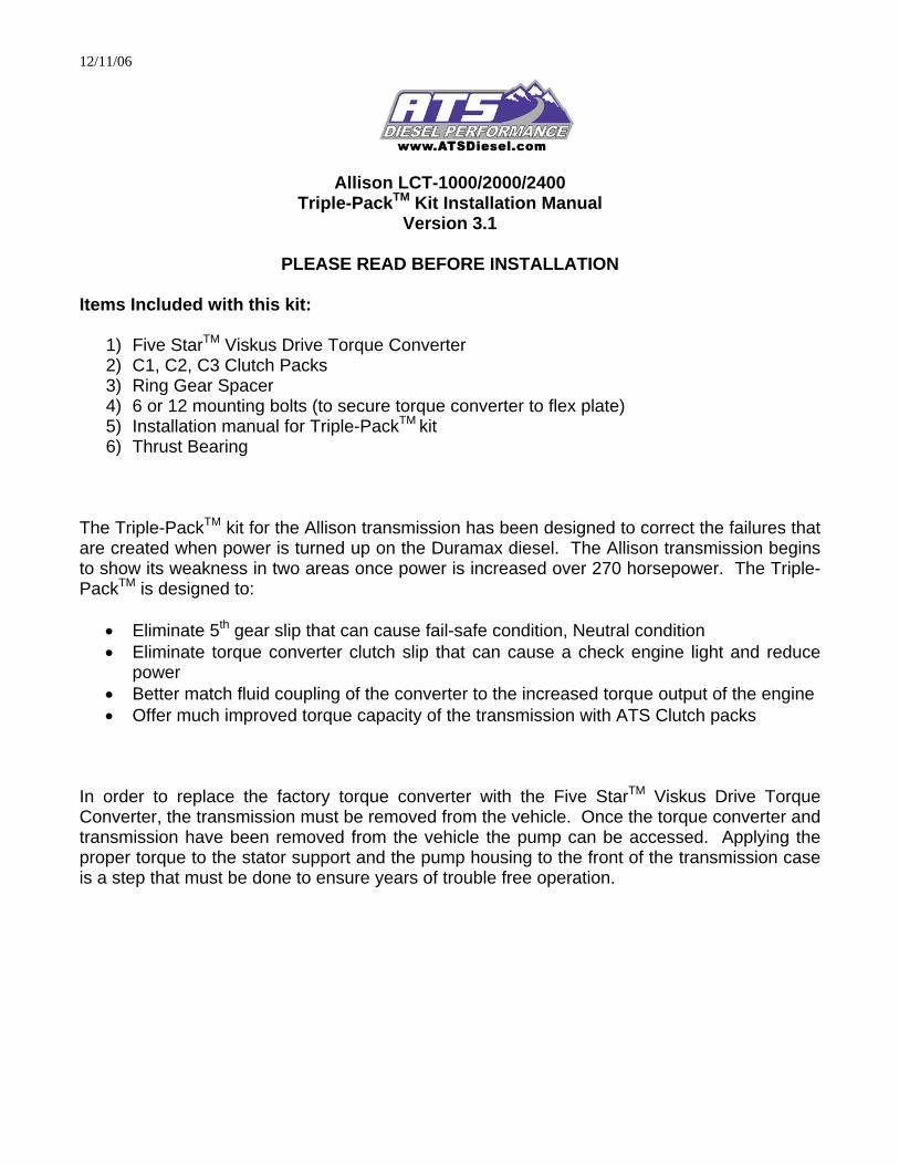
11) Remove the C-1 clutch hub and set aside for later.
Figure 9
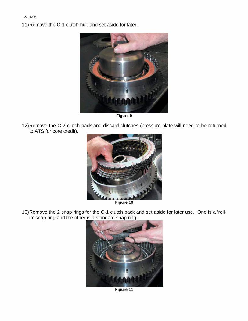
12) Remove the C-2 clutch pack and discard clutches (pressure plate will need to be returned
to ATS for core credit).
Figure 10
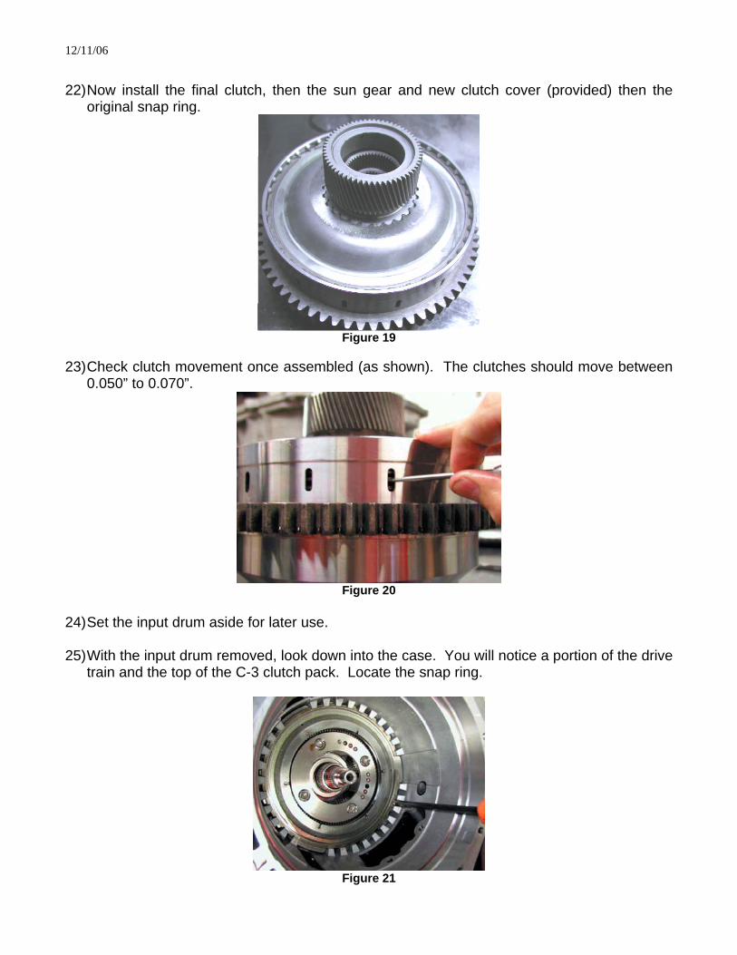
13) Remove the 2 snap rings for the C-1 clutch pack and set aside for later use. One is a ‘roll-
in’ snap ring and the other is a standard snap ring.
Figure 11

12/11/06
14) Remove the C-1 clutch pack and pressure plate, discarding the clutch pack. Set the pressure plate aside for later use.
Figure 12
15) Install the new C-1 clutch pack. Starting with the thick, apply plate, then an inside spline
clutch, then an outside spline clutch, and so on. You will end with an outside clutch on top and will have a total of 14 clutches.
Figure 13
16) Reinstall the C-1 pressure plate and the 2 snap rings. Make sure the top roll-in snap ring
seats all the way into the slot. 17) Use a 1/16 to 3/32 drill bit as a gauge for clutch clearance with the C-1 pack. The bit
should be able to slide in and out. If clearance needs to be changed, the upper pressure plate must be changed.
Allison Part #’s for C–1 back plate: 5.50 mm – 29542420 5.94 mm – 29538521 6.38 mm – 29538522 6.83 mm – 29538523 7.28 mm – 29538524 7.23 mm – 29538525
Figure 14

12/11/06
18) Reinstall the C-1 clutch hub. You will have to work the hub down as you slide the outer clutches back and forth in order to get them to spline.
19) Install the new Torrington bearing (provided) on top of the C-1 clutch hub. Reinstall the C-2
clutch hub.
Figure 15 Figure 16
20) Install the ATS C-2 clutch pack (provided) starting with a steel plate, then a clutch, and so
on, but do not install the top clutch. Make sure the 4-tab washer is installed on the C-2 clutch hub.
Figure 17
21) Install the snap ring provided in the kit into the lower groove as shown in figure 18.
Figure 18
12/11/06
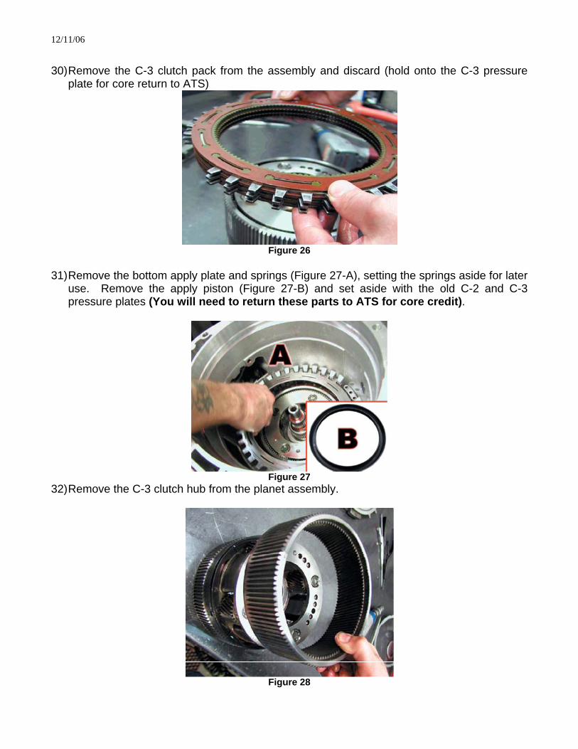
22) Now install the final clutch, then the sun gear and new clutch cover (provided) then the
original snap ring.
Figure 19
23) Check clutch movement once assembled (as shown). The clutches should move between
0.050” to 0.070”.
Figure 20
24) Set the input drum aside for later use. 25) With the input drum removed, look down into the case. You will notice a portion of the drive
train and the top of the C-3 clutch pack. Locate the snap ring.
Figure 21

12/11/06
26) Remove the snap ring (use care as it is very stiff). The C-3 pressure plate is spring loaded. 27) With the snap ring removed, lift out the C-3 pressure plate and set aside with the factory C-
2 cover plate.
Figure 22
28) Remove the top planetary gear set by lifting it out of the case (Figure 23-A). Do not pull on the center shaft or C-5 planetary (Figure 23-B), as this may dislodge the C-5 clutch pack or the spacer between the two planetary gears on the shaft. If this happens the unit must be taken completely apart to re-spline the pieces back together (Figure 24).
Figure 23 Figure 24 29) The C-3 clutch pack will lift out with the planet assembly.
Figure 25
12/11/06
30) Remove the C-3 clutch pack from the assembly and discard (hold onto the C-3 pressure
plate for core return to ATS)
Figure 26
31) Remove the bottom apply plate and springs (Figure 27-A), setting the springs aside for later
use. Remove the apply piston (Figure 27-B) and set aside with the old C-2 and C-3 pressure plates (You will need to return these parts to ATS for core credit).
Figure 27
32) Remove the C-3 clutch hub from the planet assembly.
Figure 28
12/11/06
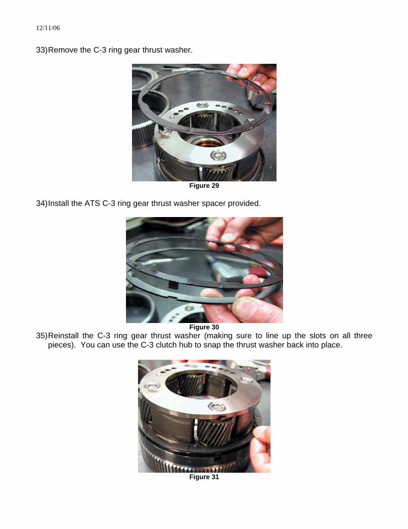
33) Remove the C-3 ring gear thrust washer.
Figure 29
34) Install the ATS C-3 ring gear thrust washer spacer provided.
Figure 30
35) Reinstall the C-3 ring gear thrust washer (making sure to line up the slots on all three pieces). You can use the C-3 clutch hub to snap the thrust washer back into place.
Figure 31
12/11/06
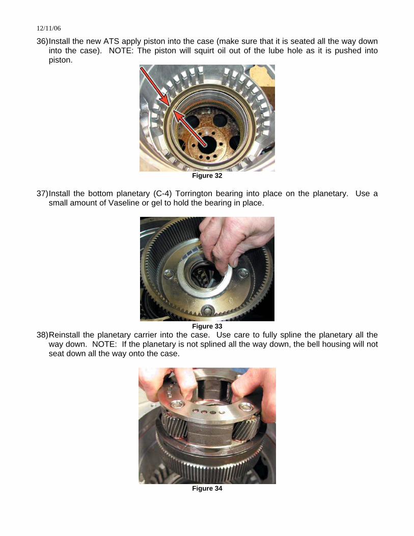
36) Install the new ATS apply piston into the case (make sure that it is seated all the way down into the case). NOTE: The piston will squirt oil out of the lube hole as it is pushed into piston.
Figure 32
37) Install the bottom planetary (C-4) Torrington bearing into place on the planetary. Use a
small amount of Vaseline or gel to hold the bearing in place.
Figure 33
38) Reinstall the planetary carrier into the case. Use care to fully spline the planetary all the way down. NOTE: If the planetary is not splined all the way down, the bell housing will not seat down all the way onto the case.
Figure 34
12/11/06
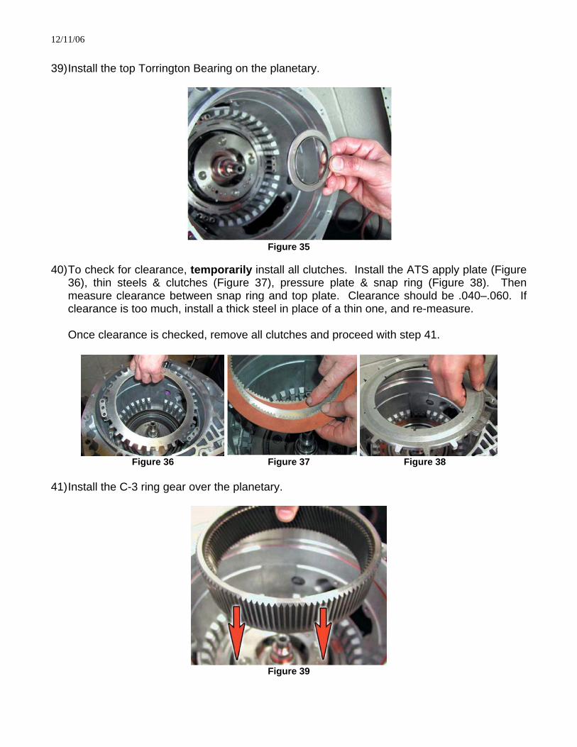
39) Install the top Torrington Bearing on the planetary.
Figure 35
40) To check for clearance, temporarily install all clutches. Install the ATS apply plate (Figure
36), thin steels & clutches (Figure 37), pressure plate & snap ring (Figure 38). Then measure clearance between snap ring and top plate. Clearance should be .040–.060. If clearance is too much, install a thick steel in place of a thin one, and re-measure.
Once clearance is checked, remove all clutches and proceed with step 41.
Figure 36 Figure 37 Figure 38
41) Install the C-3 ring gear over the planetary.
Figure 39

12/11/06
42) Install the ATS bottom apply plate with the springs installed.
Figure 40
43) Install the new ATS C-3 clutch pack into the case. Start with a clutch, then steel, making
sure the slots or notches line up on the clutches, ending with a clutch on top.
Figure 41
44) Install the new ATS pressure plate and snap ring. Use care to seat the snap ring firmly into
place.
Figure 42

12/11/06
45) Reinstall the input drum back into the case, (slightly turning the drum as it is placed back into position).
Figure 43
46) Reinstall the front pump and bell housing assembly (making sure that pump modifications
are complete). Reference steps 3-9 for reassembly. Tighten bolts to 38-45 lb/ft. 47) If installing C-4 and C-5 clutch packs you will turn the transmission over at this point and
stand it on it’s bell housing to access the tail housing.
Figure 44
48) Remove the 16 bolts holding the tail housing to the case. The housing should separate
from the case slightly. 49) Using caution not to stretch the park pawl spring, lift the housing and planet assembly off of
the case. Use a screwdriver to hold the park pawl down as you lift the housing off.
Figure 45

12/11/06
50) Remove the thrust bearing from the P3 planet or sun gear; note the direction that it seats in on the sun gear (Figure 46-A).
Figure 46
51) Remove the P3 sun gear, main shaft, spacer, and P2 sun gear (there is a thrust bearing
between the P2 sun gear and the planet).
Figure 47
52) Remove the park pawl assembly pin, followed by the park pawl, spring, and apply glide. Be
sure not to stretch the spring out of shape it will need to be replaced if this happens (Figure 46-B).
53) Remove the P2 planet and the C5 clutch pack with its backing plate.
Figure 48

12/11/06
54) Remove the snap rings holding the C-4 pressure plate in place (there are two). One is the
same as the C-3 snap ring; the other is a roll-in style.
Figure 49
55) You can now lift out the P1 planet and C-4 clutch pack. This is done the same way as the
C-3 clutch pack.
Figure 50
56) Remove the old C-4 apply piston. 57) Install the new ATS piston (provided) with the C-4 clutch pack kit. 58) Make sure that the thrust bearing is on top of the input drum sun gear and that it did not
stick to the bottom of the P1 planet. 59) Reinstall the P1 planet, making sure that the spacer and plastic washer are still in place
from the C-3 clutch pack installation. 60) Make sure that the thrust bearing is on top of the P1 planet and install the C-4 clutch pack.
This is similar to how the C-3 clutch pack was installed. 61) Install the inner snap ring. 62) Install the outer snap ring. 63) Reinstall the P2 planet, making sure that the sun gear thrust bearing is on top of the planet. 64) Install the main shaft first, then the P2 sun gear with recessed side facing down.

12/11/06
65) The side of the main shaft has a hole that is located above the P2 sun gear. This is a lube
hole for the P2 and P3 planets, which must be aligned for proper lubrication of the planets. Install the spacer making sure that one of the wide slots is positioned at the hole on the main shaft (Figure 23).
66) Install the P3 sun gear with the recessed side up with the thrust bearing on top. 67) The C5 clutch steels will have numbers stamped near the outside. Most, if not all, will have
a number ‘2’ stamped on them. Sometimes they will be stamped with the number ‘3’. If the steels have the ‘3’ stamped on them they will need to be set aside for later.
68) When reinstalling the factory C5’s or new C5 clutches from ATS, begin with the backing
plate, then a clutch, then steel and so on. If there is a steel with the number ‘3’ it will go on top.
69) Reinstall the C5 return spring (it will only install one direction, as there is an ear at the
bottom of the spring housing that fits into a slot in the bottom of the case (Figure 46-C). 70) Reinstall the park apply guide, spring, park pawl, and pin. Make sure that the spring is
holding the park pawl back to the apply guide tightly. If it is not, it will need to be replaced at this point (when not installed the coils in the spring should be tight).
71) Reinstall the tail housing assembly back onto the case. A pair of channel style locking
pliers works well on the output shaft to re-spline the P3 to P2 planet. NOTE: The housing will not drop all the way down and will be raised about one half inch due to the C5 return spring.
72) Reinstall the 16 bolts to reattach the housing, using a star pattern to tighten the bolts. Work
around the housing using this pattern in order to pull it down and draw the seams together evenly.
Special Notes: Fluid type: TransSyndTM transmission fluid or DEXRONTM III transmission fluid is recommended. Allison recommends TransSyndTM for extreme applications. Transmission fluid level is critical; there is most commonly a check engine light that will accompany a torque converter change. The check engine light will set due to the low transmission fluid level when filling the transmission. Do not be alarmed by the light, it will reset with a few ignition cycles. If you have a scan tool you can also reset it at the end of your final road test. Standard refill after service is as follows: After torque converter replacement and pan drop is approximately 15 quarts
After pan drop or valve body replacement is approximately 10.5 quarts If you are installing our Co-Pilot at the same time it will save you some time to perform the main valve body modifications when the transmission is on the ground.
12/11/06
We also recommend the installation of an ATS high capacity aluminum pan at the same time the ATS Triple-Pack Kit or Co-Pilot kit is installed. Be sure to visit www.ATSDiesel.com for other products for you or your customers! Notes about Startup procedure after Installation Keep the vehicle in park during first ten minutes of startup. This will allow any debris in the cooling system to fall into the sump instead of going into the valve body. To avoid a fail-safe condition and/or check engine light, the recommended procedure is to fill the transmission with a minimum of 6 quarts (with stock pan) of fluid before startup. With the high capacity pan you will want to 11 to 12 quarts before startup. Once the engine is started, allow it to run for 4-5 seconds and then shut off the ignition. Allow the vehicle to sit for 5-10 seconds and then restart the engine. This will purge the air from the system before the OEM computer detects the low pressure (therefore setting the check engine light and trouble code). It is recommended to let the vehicle idle for 5-10 minutes, in park, before putting into gear, to let oil circulate, and purge air from the system. Scan Tools Different scan tools can often be misleading. The only scan tool that ATS has found to be completely effective at thoroughly clearing trouble codes in the computer is the GM Tech II scanner and the Viewtronics hand-held scanner. Many other scan tools on the market display to the user that they are clearing the codes, when in fact they are not. This condition of not completely clearing the codes has been exhibited repeatedly with the SnapOn scanners. Disconnecting the battery cables from the battery terminals WILL NOT clear the codes or the adaptive strategy that governs shift behavior. Feel free to contact our tech department for questions or details. Diagnostics If a no engagement condition exists after installing the transmission, the 20-pin connector can be unplugged from the back of the unit with the engine running. With the 20-pin connector disconnected from the transmission, the transmission will engage forward and reverse. This ensures the integrity of the internals on the transmission.
Thank You for choosing ATS Diesel Performance!

12/11/06
ATS Diesel Performance
Limited Warranty Statement ATS Diesel Performance warrants the original purchaser that any parts purchased shall be free from defects in material and workmanship. ATS Diesel Performance is the warrantor of this product, in the event this produce is purchased form a distributor or retailer other that ATS Diesel Performance the customer must contact ATS Diesel Performance for any warranty concerns, not the purchasing dealer. A defect is defined as a condition that would render the product inoperable. This warranty does not cover deteriorating of plating, paint or any other coating. ATS liability is limited to the repair or replacement, at ATS’s option, of any warrantable product returned prepaid with a complete service history and proof of purchase to the factory. A valid proof of purchase is a dated bill of sale. Repaired or replaced, product will be returned to the customer, freight collect on a like-for-like part number basis. Accepted warranty units, which have been replaced, become the sole property of ATS. A Return Product Authorization number obtained in advance from an ATS customer service representative must accompany products returned for warranty determination. ATS will be the final authority on all warranty decisions. This warranty shall not apply to any unit which has been improperly stored or installed, subjected to misapplication, improper operating conditions, accidents, or neglect; or which has been improperly repaired, altered or otherwise mistreated by the owner or his agent. This warranty shall terminate at the end of 12 months in service with the original user. Labor cost incurred by the removal and replacement of an ATS product, while performing warranty work, will be the responsibility of the vehicle owner; in no case does the obligation of ATS Diesel Performance exceed the original purchase price of the product as indicated on the original bill of sale. Except as set forth in this warranty, ATS disclaims any implied warranty, including implied warranties of merchantability and fitness for a particular purpose. ATS also disclaims any liability for incidental or consequential damages including, but not limited to, repair labor, rental vehicles, hotel costs or any other inconvenience costs. This warranty is in lieu of all warranties or guarantees, either expressed or implied, and shall not extend to any customer or to any person other than the original purchaser residing within the boundaries of the continental US or Canada.
©2005 ATSdiesel.com