troubleshooting hardware and booting · pdf file3-2 internetworking troubleshooting handbook,...
TRANSCRIPT
Internetworking Troub1-58705-005-6
C H A P T E R 3
Troubleshooting Hardware and Booting ProblemsThis chapter provides procedures for troubleshooting hardware and booting problems. Although it provides specific procedures for some Cisco products, always refer to your hardware installation and maintenance publication for more detailed information about your specific platform, including descriptions of specific LEDs, configuration information, and additional troubleshooting information.
This chapter begins with the following sections on hardware problems:
• Cisco 7500 Series Startup—Describes hardware and boot process troubleshooting for Cisco 7500 series routers
• Cisco 7000 Series Startup—Describes hardware and boot process troubleshooting for Cisco 7000 series routers
• Cisco 4000 Series Startup—Describes hardware and boot process troubleshooting for Cisco 4000 series routers
• Cisco 2500 Series Startup—Describes hardware and boot process troubleshooting for Cisco 2500 series routers
• Catalyst 5000 Series Startup—Describes hardware and boot process troubleshooting for Catalyst 5000 series LAN switches
• Catalyst 2900 Series Startup—Describes hardware and boot process troubleshooting for Catalyst 2900 series LAN switches
• Testing and Verifying Replacement Parts—Provides suggested actions when swapping router hardware
• Catalyst 6000 Series Startup—Describes hardware and boot process troubleshooting for Catalyst 6000 series LAN switches
• Cisco 2600 Series Startup—Describes hardware and boot process troubleshooting for Cisco 2600 series routers
• Cisco 3600 Series Startup—Describes hardware and boot process troubleshooting for Cisco 3600 series routers
• Catalyst 4000 Series Startup—Describes hardware and boot process troubleshooting for Catalyst 4000 series LAN switches
The remaining sections describe symptoms, problems, and solutions for Flash boot, network boot using TFTP, ROM boot, and other bootup problems:
• Booting: Router Fails to Boot from Flash Memory
• Booting: Vector Error Occurs When Booting from Flash Memory
3-1leshooting Handbook, Second Edition
Chapter 3 Troubleshooting Hardware and Booting ProblemsBooting the Router
• Booting: Router Partially Boots from Flash and Displays Boot Prompt
• Booting: Router Cannot Network boot from TFTP Server
• Booting: Router Cannot Network boot from Another Router
• Booting: Timeouts and Out-of-Order Packets Prevent Network booting
• Booting: Invalid Routes Prevent Network booting
• Booting: Client ARP Requests Timeout During Network boot
• Booting: Undefined Load Module Error When Network booting
• Booting: Router Hangs After ROM Monitor Initializes
• Booting: Router Is Stuck in ROM Monitor Mode
• Booting: Scrambled Output When Booting from ROM
• Booting: Local Timeouts Occur When Booting from ROM
• Booting: Unresponsive Terminal Connection to Unconfigured Access Server
Booting the RouterCisco routers can initialize the system (boot) in four ways:
• Network boot—Routers can boot from a server using the Trivial File Transfer Protocol (TFTP), the DEC Maintenance Operation Protocol (MOP), or the Remote Copy Protocol (RCP) across any of the supported media types (such as Ethernet, Token Ring, Fiber Distributed Data Interface [FDDI], High-Speed Serial Interface [HSSI], and serial lines).
• Flash memory—Routers can boot from Flash memory, a nonvolatile storage medium that can be electrically erased and reprogrammed.
• ROM—Routers can boot a system from built-in read-only memory (ROM).
• PC Flash memory card—Routers can boot from a removable Flash memory card.
This section provides general information about router booting.
Network Booting TipsDuring network booting sessions, routers behave like hosts. They route via proxy Address Resolution Protocol (ARP), Serial Line Address Resolution Protocol (SLARP) information, Internet Control Message Protocol (ICMP) redirects, or a default gateway. When network booting, routers ignore dynamic routing information, static IP routes, and bridging information. As a result, intermediate routers are responsible for handling ARP and User Datagram Protocol (UDP) requests correctly. For serial and HSSI media, ARP is not used.
Before network booting from a server, you should ping the server from the ROM software. If you cannot ping the server, follow the procedures described in the section “Booting: Router Cannot Network boot from TFTP Server,” later in this chapter. If you still cannot ping the server, there is probably a server configuration or hardware problem. Refer to your TFTP server documentation, or contact your technical support representative for assistance.
3-2Internetworking Troubleshooting Handbook, Second Edition
1-58705-005-6
Chapter 3 Troubleshooting Hardware and Booting ProblemsBooting the Router
Fault-Tolerant Boot StrategiesAlthough network booting is useful, network or server failures can make network booting impossible. After you have installed and configured the router’s Flash memory, configure the boot sequence for the router to reduce the impact of a server or network failure. The following order is recommended:
1. Boot an image from Flash memory.
2. Boot an image using a network boot.
3. Boot from a ROM image.
The following is an example of how to configure a router with a fault-tolerant boot sequence.
goriot# configure terminalEnter configuration commands, one per line. End with CNTL/Z.goriot(config)# boot system flash gsxxgoriot(config)# boot system gsxx 131.108.1.101goriot(config)# boot system romgoriot(config)# ^Zgoriot#%SYS-5-CONFIG_I: Configured from console by consolegoriot# copy running-config startup-config[ok]goriot#
Using this strategy, a router has three sources from which to boot: Flash memory, network boot, and ROM. Providing alternative sources can help to mitigate any failure of the TFTP server or the network.
Note The configuration register must be set to allow ROM image booting after failed network booting attempts. For more information, refer to the hardware configuration manual for your platform.
Timeouts and Out-of-Order PacketsWhen network booting, a client might need to retransmit requests before receiving a response to an ARP request. These retransmissions can result in timeouts and out-of-order packets.
Timeouts (shown as periods in a network booting display) and out-of-order packets (shown as uppercase O’s) do not necessarily prevent a successful network boot. It is acceptable to have either or both timeouts or out-of-order packets occur during the network boot process.
The following examples show console output from network booting sessions that were successful even though timeouts and out-of-order packets occurred (exclamation points represent successfully received packets):
Booting gs3-bfx from 131.108.1.123: !.!!!!!!!!!!!!!!!!!!!!!!
Booting gs3-bfx from 131.108.1.123: !O.O!!!!!!!!!!!!!!!!!!!!!!
If a network boot generates excessive out-of-order packets and timeouts, problems might result. These problems are discussed later in this chapter, in the section “Booting: Timeouts and Out-of-Order Packets Prevent Network booting.”
3-3Internetworking Troubleshooting Handbook, Second Edition
1-58705-005-6
Chapter 3 Troubleshooting Hardware and Booting ProblemsTroubleshooting Hardware
Information for Technical SupportIf you cannot resolve your booting problem using the procedures outlined in this chapter, collect the following information for your technical support representative:
• ROM images. (Use the show version exec command.)
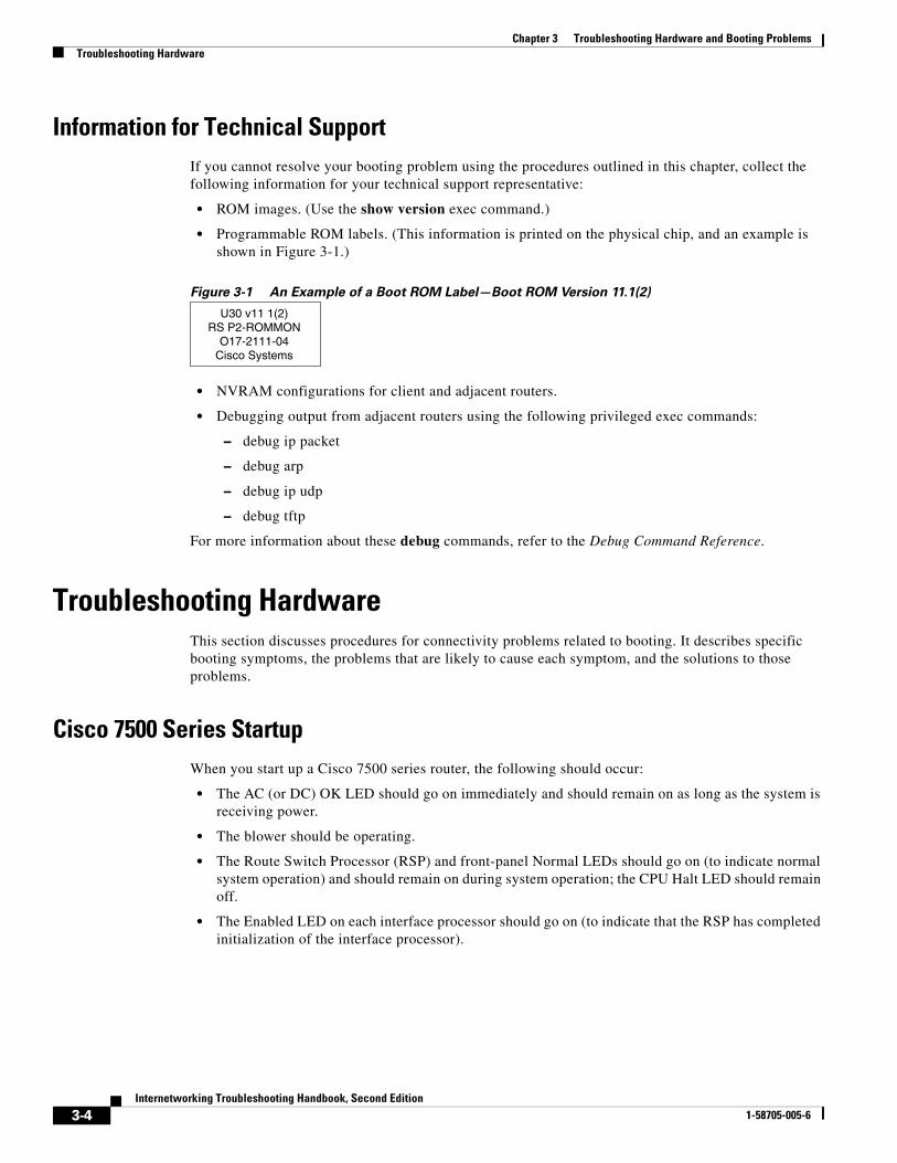
• Programmable ROM labels. (This information is printed on the physical chip, and an example is shown in Figure 3-1.)
Figure 3-1 An Example of a Boot ROM Label—Boot ROM Version 11.1(2)
• NVRAM configurations for client and adjacent routers.
• Debugging output from adjacent routers using the following privileged exec commands:
– debug ip packet
– debug arp
– debug ip udp
– debug tftp
For more information about these debug commands, refer to the Debug Command Reference.
Troubleshooting HardwareThis section discusses procedures for connectivity problems related to booting. It describes specific booting symptoms, the problems that are likely to cause each symptom, and the solutions to those problems.
Cisco 7500 Series StartupWhen you start up a Cisco 7500 series router, the following should occur:
• The AC (or DC) OK LED should go on immediately and should remain on as long as the system is receiving power.
• The blower should be operating.
• The Route Switch Processor (RSP) and front-panel Normal LEDs should go on (to indicate normal system operation) and should remain on during system operation; the CPU Halt LED should remain off.
• The Enabled LED on each interface processor should go on (to indicate that the RSP has completed initialization of the interface processor).
U30 v11 1(2)RS P2-ROMMON
O17-2111-04Cisco Systems
3-4Internetworking Troubleshooting Handbook, Second Edition
1-58705-005-6
Chapter 3 Troubleshooting Hardware and Booting ProblemsTroubleshooting Hardware
When the 7500 series system has initialized successfully, the system banner should be displayed on the console screen. If it is not displayed, make sure that the console terminal is properly connected to the RSP console port and that the terminal is set correctly. The system banner should look similar to the following:
System Bootstrap, Version 4.6(5), SOFTWARECopyright (c) 1986-1995 by cisco SystemsRSP2 processor with 16384 Kbytes of memory### [...] ###F3: 2012356+47852+194864 at 0x1000 Restricted Rights LegendUse, duplication, or disclosure by the Government issubject to restrictions as set forth in subparagraph(c) of the Commercial Computer Software - RestrictedRights clause at FAR sec. 52.227-19 and subparagraph(c) (1) (ii) of the Rights in Technical Data and ComputerSoftware clause at DFARS sec. 252.227-7013. cisco Systems, Inc. 170 Tasman Drive San Jose, CA 95134GS Software (RSP-K), Version 10.3(571) [fc3], RELEASE SOFTWARECopyright (c) 1986-1995 by cisco Systems, Inc.[...]Press RETURN to get started!
If a problem occurs, try to isolate the problem to a specific subsystem. The Cisco 7500 series routers have the following subsystems:
• Power subsystem—Includes power supplies, external power cable, and backplane
• Cooling subsystem—Depending on your system, includes the following:
– Cisco 7505—Fan tray, fan tray spare with six individual fans, and fan control board
– Cisco 7507—Chassis blower
– Cisco 7513—Blower module, including blower, blower-speed control board, front-panel LEDs, and the module itself
• Processor subsystem—Depending on your system, includes all interface processors and either the RSP1 or the RSP2
3-5Internetworking Troubleshooting Handbook, Second Edition
1-58705-005-6

Chapter 3 Troubleshooting Hardware and Booting ProblemsTroubleshooting Hardware
Table 3-1 outlines the areas where Cisco 7500 series startup problems may occur and describes solutions to those problems.
3-6Internetworking Troubleshooting Handbook, Second Edition
1-58705-005-6
Chapter 3 Troubleshooting Hardware and Booting ProblemsTroubleshooting Hardware
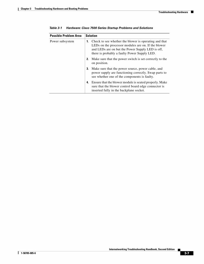
Table 3-1 Hardware: Cisco 7500 Series Startup Problems and Solutions
Possible Problem Area Solution
Power subsystem 1. Check to see whether the blower is operating and that LEDs on the processor modules are on. If the blower and LEDs are on but the Power Supply LED is off, there is probably a faulty Power Supply LED.
2. Make sure that the power switch is set correctly to the on position.
3. Make sure that the power source, power cable, and power supply are functioning correctly. Swap parts to see whether one of the components is faulty.
4. Ensure that the blower module is seated properly. Make sure that the blower control board edge connector is inserted fully in the backplane socket.
3-7Internetworking Troubleshooting Handbook, Second Edition
1-58705-005-6
Chapter 3 Troubleshooting Hardware and Booting ProblemsTroubleshooting Hardware
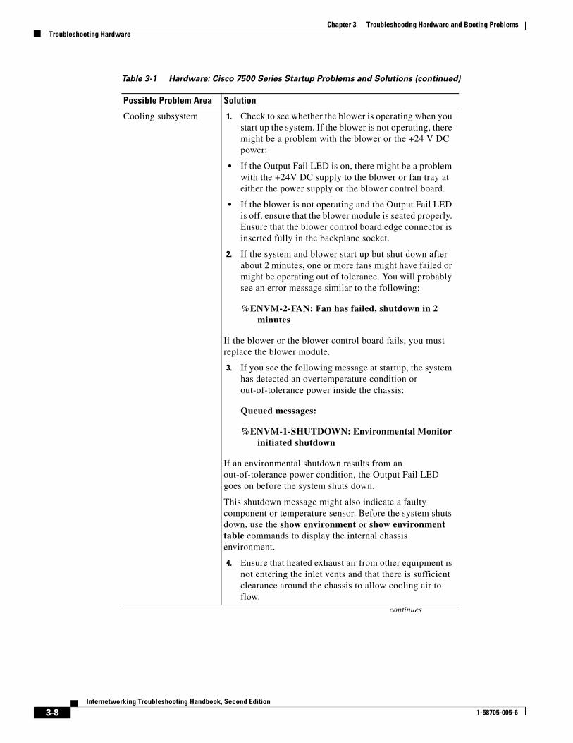
Cooling subsystem 1. Check to see whether the blower is operating when you start up the system. If the blower is not operating, there might be a problem with the blower or the +24 V DC power:
• If the Output Fail LED is on, there might be a problem with the +24V DC supply to the blower or fan tray at either the power supply or the blower control board.
• If the blower is not operating and the Output Fail LED is off, ensure that the blower module is seated properly. Ensure that the blower control board edge connector is inserted fully in the backplane socket.
2. If the system and blower start up but shut down after about 2 minutes, one or more fans might have failed or might be operating out of tolerance. You will probably see an error message similar to the following:
%ENVM-2-FAN: Fan has failed, shutdown in 2 minutes
If the blower or the blower control board fails, you must replace the blower module.
3. If you see the following message at startup, the system has detected an overtemperature condition or out-of-tolerance power inside the chassis:
Queued messages:
%ENVM-1-SHUTDOWN: Environmental Monitor initiated shutdown
If an environmental shutdown results from an out-of-tolerance power condition, the Output Fail LED goes on before the system shuts down.
This shutdown message might also indicate a faulty component or temperature sensor. Before the system shuts down, use the show environment or show environment table commands to display the internal chassis environment.
4. Ensure that heated exhaust air from other equipment is not entering the inlet vents and that there is sufficient clearance around the chassis to allow cooling air to flow.
Table 3-1 Hardware: Cisco 7500 Series Startup Problems and Solutions (continued)
Possible Problem Area Solution
continues
3-8Internetworking Troubleshooting Handbook, Second Edition
1-58705-005-6
Chapter 3 Troubleshooting Hardware and Booting ProblemsTroubleshooting Hardware
Cisco 7000 Series StartupWhen you start up a Cisco 7000 series router, the following should occur:
• The DC OK LED should go on and should remain on as long as the system is receiving source power.
• The fans should be operating.
• The Route Processor (RP) Normal LED should go on and stay on to indicate normal system operation; the Halt CPU LED should remain off.
• The Enabled LED on the Switch Processor (SP) or Silicon Switch Processor (SSP) and each interface processor should go on when the RP has completed initialization of the interface processor or SP (or SSP) for operation.
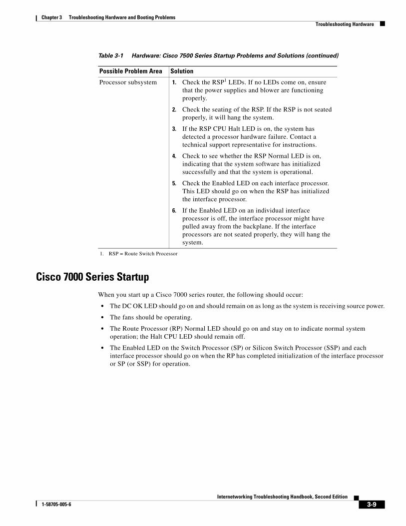
Processor subsystem 1. Check the RSP1 LEDs. If no LEDs come on, ensure that the power supplies and blower are functioning properly.
2. Check the seating of the RSP. If the RSP is not seated properly, it will hang the system.
3. If the RSP CPU Halt LED is on, the system has detected a processor hardware failure. Contact a technical support representative for instructions.
4. Check to see whether the RSP Normal LED is on, indicating that the system software has initialized successfully and that the system is operational.
5. Check the Enabled LED on each interface processor. This LED should go on when the RSP has initialized the interface processor.
6. If the Enabled LED on an individual interface processor is off, the interface processor might have pulled away from the backplane. If the interface processors are not seated properly, they will hang the system.
1. RSP = Route Switch Processor
Table 3-1 Hardware: Cisco 7500 Series Startup Problems and Solutions (continued)
Possible Problem Area Solution
3-9Internetworking Troubleshooting Handbook, Second Edition
1-58705-005-6
Chapter 3 Troubleshooting Hardware and Booting ProblemsTroubleshooting Hardware
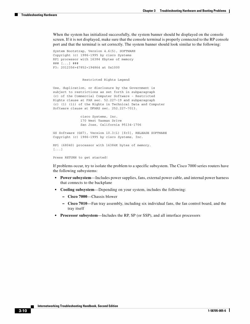
When the system has initialized successfully, the system banner should be displayed on the console screen. If it is not displayed, make sure that the console terminal is properly connected to the RP console port and that the terminal is set correctly. The system banner should look similar to the following:
System Bootstrap, Version 4.6(5), SOFTWARECopyright (c) 1986-1995 by cisco SystemsRP1 processor with 16384 Kbytes of memory### [...] ###F3: 2012356+47852+194864 at 0x1000
Restricted Rights Legend
Use, duplication, or disclosure by the Government issubject to restrictions as set forth in subparagraph(c) of the Commercial Computer Software - RestrictedRights clause at FAR sec. 52.227-19 and subparagraph(c) (1) (ii) of the Rights in Technical Data and ComputerSoftware clause at DFARS sec. 252.227-7013.
cisco Systems, Inc. 170 West Tasman Drive San Jose, California 95134-1706
GS Software (GS7), Version 10.3(1) [fc3], RELEASE SOFTWARECopyright (c) 1986-1995 by cisco Systems, Inc.
RP1 (68040) processor with 16384K bytes of memory.[...]
Press RETURN to get started!
If problems occur, try to isolate the problem to a specific subsystem. The Cisco 7000 series routers have the following subsystems:
• Power subsystem—Includes power supplies, fans, external power cable, and internal power harness that connects to the backplane
• Cooling subsystem—Depending on your system, includes the following:
– Cisco 7000—Chassis blower
– Cisco 7010—Fan tray assembly, including six individual fans, the fan control board, and the tray itself
• Processor subsystem—Includes the RP, SP (or SSP), and all interface processors
3-10Internetworking Troubleshooting Handbook, Second Edition
1-58705-005-6
Chapter 3 Troubleshooting Hardware and Booting ProblemsTroubleshooting Hardware
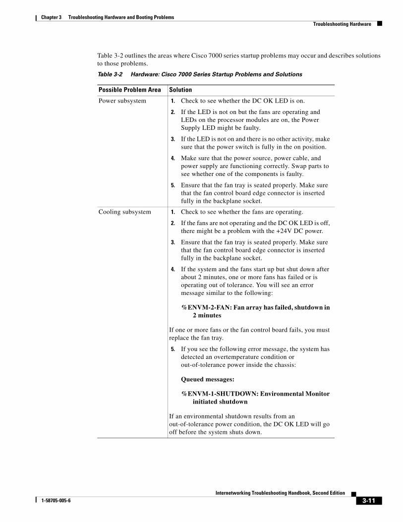
Table 3-2 outlines the areas where Cisco 7000 series startup problems may occur and describes solutions to those problems.
Table 3-2 Hardware: Cisco 7000 Series Startup Problems and Solutions
Possible Problem Area Solution
Power subsystem 1. Check to see whether the DC OK LED is on.
2. If the LED is not on but the fans are operating and LEDs on the processor modules are on, the Power Supply LED might be faulty.
3. If the LED is not on and there is no other activity, make sure that the power switch is fully in the on position.
4. Make sure that the power source, power cable, and power supply are functioning correctly. Swap parts to see whether one of the components is faulty.
5. Ensure that the fan tray is seated properly. Make sure that the fan control board edge connector is inserted fully in the backplane socket.
Cooling subsystem 1. Check to see whether the fans are operating.
2. If the fans are not operating and the DC OK LED is off, there might be a problem with the +24V DC power.
3. Ensure that the fan tray is seated properly. Make sure that the fan control board edge connector is inserted fully in the backplane socket.
4. If the system and the fans start up but shut down after about 2 minutes, one or more fans has failed or is operating out of tolerance. You will see an error message similar to the following:
%ENVM-2-FAN: Fan array has failed, shutdown in 2 minutes
If one or more fans or the fan control board fails, you must replace the fan tray.
5. If you see the following error message, the system has detected an overtemperature condition or out-of-tolerance power inside the chassis:
Queued messages:
%ENVM-1-SHUTDOWN: Environmental Monitor initiated shutdown
If an environmental shutdown results from an out-of-tolerance power condition, the DC OK LED will go off before the system shuts down.
3-11Internetworking Troubleshooting Handbook, Second Edition
1-58705-005-6
Chapter 3 Troubleshooting Hardware and Booting ProblemsTroubleshooting Hardware
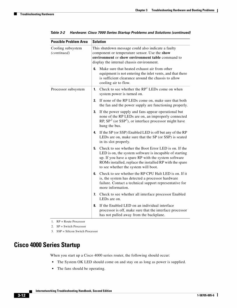
Cisco 4000 Series StartupWhen you start up a Cisco 4000 series router, the following should occur:
• The System OK LED should come on and stay on as long as power is supplied.
• The fans should be operating.
Cooling subsystem (continued)
This shutdown message could also indicate a faulty component or temperature sensor. Use the show environment or show environment table command to display the internal chassis environment.
6. Make sure that heated exhaust air from other equipment is not entering the inlet vents, and that there is sufficient clearance around the chassis to allow cooling air to flow.
Processor subsystem 1. Check to see whether the RP1 LEDs come on when system power is turned on.
2. If none of the RP LEDs come on, make sure that both the fan and the power supply are functioning properly.
3. If the power supply and fans appear operational but none of the RP LEDs are on, an improperly connected RP, SP 2 (or SSP3), or interface processor might have hung the bus.
4. If the SP (or SSP) Enabled LED is off but any of the RP LEDs are on, make sure that the SP (or SSP) is seated in its slot properly.
5. Check to see whether the Boot Error LED is on. If the LED is on, the system software is incapable of starting up. If you have a spare RP with the system software ROMs installed, replace the installed RP with the spare to see whether the system will boot.
6. Check to see whether the RP CPU Halt LED is on. If it is, the system has detected a processor hardware failure. Contact a technical support representative for more information.
7. Check to see whether all interface processor Enabled LEDs are on.
8. If the Enabled LED on an individual interface processor is off, make sure that the interface processor has not pulled away from the backplane.
1. RP = Route Processor
2. SP = Switch Processor
3. SSP = Silicon Switch Processor
Table 3-2 Hardware: Cisco 7000 Series Startup Problems and Solutions (continued)
Possible Problem Area Solution
3-12Internetworking Troubleshooting Handbook, Second Edition
1-58705-005-6
Chapter 3 Troubleshooting Hardware and Booting ProblemsTroubleshooting Hardware
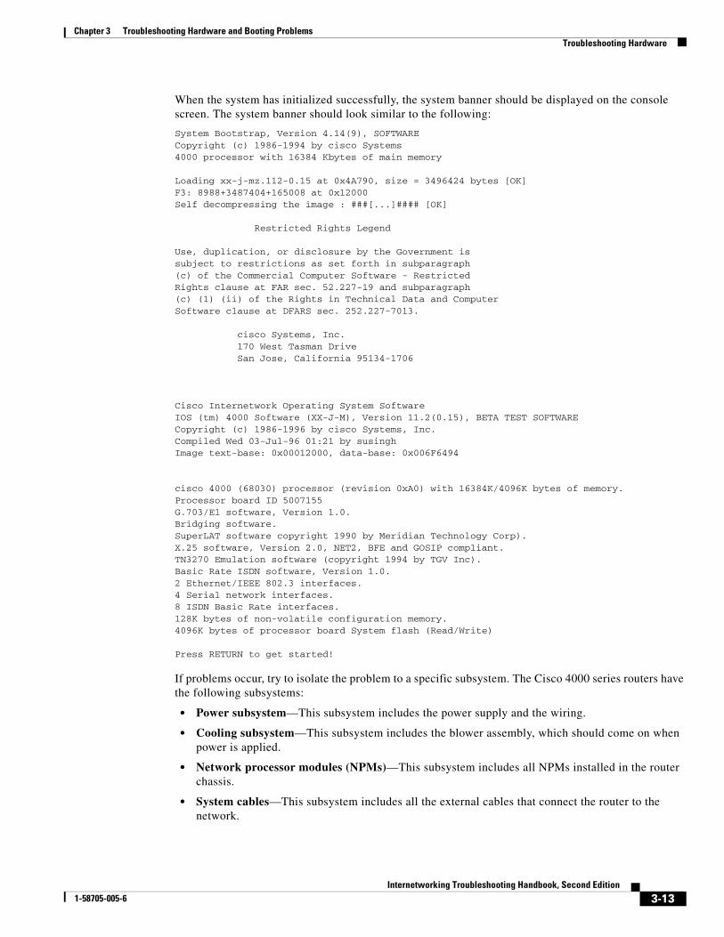
When the system has initialized successfully, the system banner should be displayed on the console screen. The system banner should look similar to the following:
System Bootstrap, Version 4.14(9), SOFTWARECopyright (c) 1986-1994 by cisco Systems4000 processor with 16384 Kbytes of main memory
Loading xx-j-mz.112-0.15 at 0x4A790, size = 3496424 bytes [OK]F3: 8988+3487404+165008 at 0x12000Self decompressing the image : ###[...]#### [OK]
Restricted Rights Legend
Use, duplication, or disclosure by the Government issubject to restrictions as set forth in subparagraph(c) of the Commercial Computer Software - RestrictedRights clause at FAR sec. 52.227-19 and subparagraph(c) (1) (ii) of the Rights in Technical Data and ComputerSoftware clause at DFARS sec. 252.227-7013.
cisco Systems, Inc. 170 West Tasman Drive San Jose, California 95134-1706
Cisco Internetwork Operating System SoftwareIOS (tm) 4000 Software (XX-J-M), Version 11.2(0.15), BETA TEST SOFTWARECopyright (c) 1986-1996 by cisco Systems, Inc.Compiled Wed 03-Jul-96 01:21 by susinghImage text-base: 0x00012000, data-base: 0x006F6494
cisco 4000 (68030) processor (revision 0xA0) with 16384K/4096K bytes of memory.Processor board ID 5007155G.703/E1 software, Version 1.0.Bridging software.SuperLAT software copyright 1990 by Meridian Technology Corp).X.25 software, Version 2.0, NET2, BFE and GOSIP compliant.TN3270 Emulation software (copyright 1994 by TGV Inc).Basic Rate ISDN software, Version 1.0.2 Ethernet/IEEE 802.3 interfaces.4 Serial network interfaces.8 ISDN Basic Rate interfaces.128K bytes of non-volatile configuration memory.4096K bytes of processor board System flash (Read/Write)
Press RETURN to get started!
If problems occur, try to isolate the problem to a specific subsystem. The Cisco 4000 series routers have the following subsystems:
• Power subsystem—This subsystem includes the power supply and the wiring.
• Cooling subsystem—This subsystem includes the blower assembly, which should come on when power is applied.
• Network processor modules (NPMs)—This subsystem includes all NPMs installed in the router chassis.
• System cables—This subsystem includes all the external cables that connect the router to the network.
3-13Internetworking Troubleshooting Handbook, Second Edition
1-58705-005-6

Chapter 3 Troubleshooting Hardware and Booting ProblemsTroubleshooting Hardware
Table 3-3 outlines the areas where Cisco 4000 series startup problems may occur and describes solutions to those problems.
Cisco 2500 Series StartupWhen you start up a Cisco 2500 series router, the following should occur:
• The System OK LED should come on and stay on as long as power is supplied.
• The fans should be operating.
Table 3-3 Hardware: Cisco 4000 Series Startup Problems and Solutions
Possible Problem Area Solution
Power and cooling subsystems
1. Check to see whether the blower is operating. If it is not, check the AC power input, AC power source, router circuit breaker, and power supply cable.
2. If the system shuts down after being on a short time, check the power supply. If the power supply appears operational, the router might have shut down due to overheating. Check the console for error messages similar to the following:
%SYS-1-OVERTEMP: System detected OVERTEMPERATURE condition. Please resolve cooling problem immediately!
Make sure that the fans are working and that there is no air blockage to cooling vents.
3. If the system partially boots but LEDs do not light, contact your technical support representative.
NPMs1 and cables 1. Make sure that NPMs are properly connected to the motherboard connector.
2. Check the external cables.
3. Check the processor or software for proper configuration.
4. Check the external console connection and verify that the console baud rate is correct.
1. NPMs = network processor modules
3-14Internetworking Troubleshooting Handbook, Second Edition
1-58705-005-6
Chapter 3 Troubleshooting Hardware and Booting ProblemsTroubleshooting Hardware
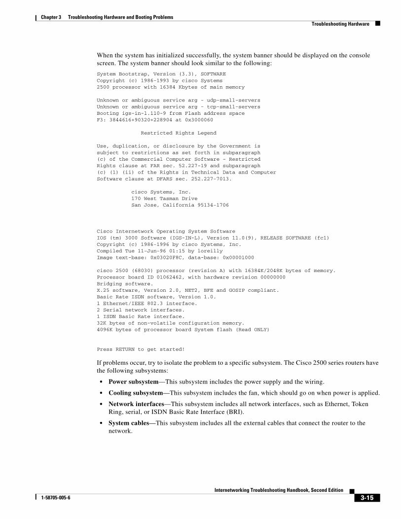
When the system has initialized successfully, the system banner should be displayed on the console screen. The system banner should look similar to the following:
System Bootstrap, Version (3.3), SOFTWARECopyright (c) 1986-1993 by cisco Systems2500 processor with 16384 Kbytes of main memory
Unknown or ambiguous service arg - udp-small-serversUnknown or ambiguous service arg - tcp-small-serversBooting igs-in-l.110-9 from Flash address spaceF3: 3844616+90320+228904 at 0x3000060
Restricted Rights Legend
Use, duplication, or disclosure by the Government issubject to restrictions as set forth in subparagraph(c) of the Commercial Computer Software - RestrictedRights clause at FAR sec. 52.227-19 and subparagraph(c) (1) (ii) of the Rights in Technical Data and ComputerSoftware clause at DFARS sec. 252.227-7013.
cisco Systems, Inc. 170 West Tasman Drive San Jose, California 95134-1706
Cisco Internetwork Operating System SoftwareIOS (tm) 3000 Software (IGS-IN-L), Version 11.0(9), RELEASE SOFTWARE (fc1)Copyright (c) 1986-1996 by cisco Systems, Inc.Compiled Tue 11-Jun-96 01:15 by loreillyImage text-base: 0x03020F8C, data-base: 0x00001000
cisco 2500 (68030) processor (revision A) with 16384K/2048K bytes of memory.Processor board ID 01062462, with hardware revision 00000000Bridging software.X.25 software, Version 2.0, NET2, BFE and GOSIP compliant.Basic Rate ISDN software, Version 1.0.1 Ethernet/IEEE 802.3 interface.2 Serial network interfaces.1 ISDN Basic Rate interface.32K bytes of non-volatile configuration memory.4096K bytes of processor board System flash (Read ONLY)
Press RETURN to get started!
If problems occur, try to isolate the problem to a specific subsystem. The Cisco 2500 series routers have the following subsystems:
• Power subsystem—This subsystem includes the power supply and the wiring.
• Cooling subsystem—This subsystem includes the fan, which should go on when power is applied.
• Network interfaces—This subsystem includes all network interfaces, such as Ethernet, Token Ring, serial, or ISDN Basic Rate Interface (BRI).
• System cables—This subsystem includes all the external cables that connect the router to the network.
3-15Internetworking Troubleshooting Handbook, Second Edition
1-58705-005-6
Chapter 3 Troubleshooting Hardware and Booting ProblemsTroubleshooting Hardware
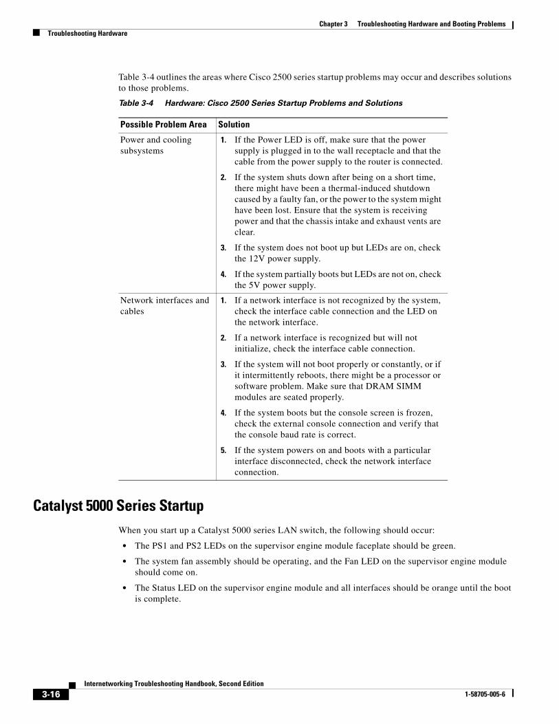
Table 3-4 outlines the areas where Cisco 2500 series startup problems may occur and describes solutions to those problems.
Catalyst 5000 Series StartupWhen you start up a Catalyst 5000 series LAN switch, the following should occur:
• The PS1 and PS2 LEDs on the supervisor engine module faceplate should be green.
• The system fan assembly should be operating, and the Fan LED on the supervisor engine module should come on.
• The Status LED on the supervisor engine module and all interfaces should be orange until the boot is complete.
Table 3-4 Hardware: Cisco 2500 Series Startup Problems and Solutions
Possible Problem Area Solution
Power and cooling subsystems
1. If the Power LED is off, make sure that the power supply is plugged in to the wall receptacle and that the cable from the power supply to the router is connected.
2. If the system shuts down after being on a short time, there might have been a thermal-induced shutdown caused by a faulty fan, or the power to the system might have been lost. Ensure that the system is receiving power and that the chassis intake and exhaust vents are clear.
3. If the system does not boot up but LEDs are on, check the 12V power supply.
4. If the system partially boots but LEDs are not on, check the 5V power supply.
Network interfaces and cables
1. If a network interface is not recognized by the system, check the interface cable connection and the LED on the network interface.
2. If a network interface is recognized but will not initialize, check the interface cable connection.
3. If the system will not boot properly or constantly, or if it intermittently reboots, there might be a processor or software problem. Make sure that DRAM SIMM modules are seated properly.
4. If the system boots but the console screen is frozen, check the external console connection and verify that the console baud rate is correct.
5. If the system powers on and boots with a particular interface disconnected, check the network interface connection.
3-16Internetworking Troubleshooting Handbook, Second Edition
1-58705-005-6
Chapter 3 Troubleshooting Hardware and Booting ProblemsTroubleshooting Hardware
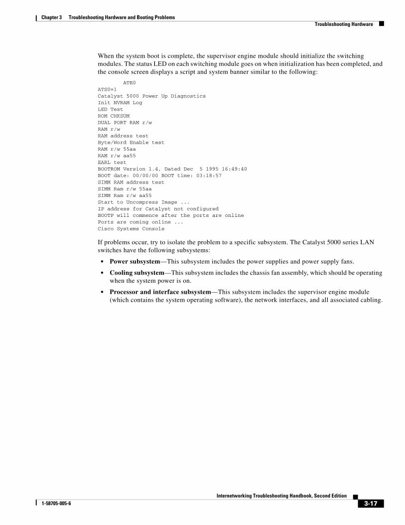
When the system boot is complete, the supervisor engine module should initialize the switching modules. The status LED on each switching module goes on when initialization has been completed, and the console screen displays a script and system banner similar to the following:
ATE0ATS0=1Catalyst 5000 Power Up DiagnosticsInit NVRAM LogLED TestROM CHKSUMDUAL PORT RAM r/wRAM r/wRAM address testByte/Word Enable testRAM r/w 55aaRAM r/w aa55EARL testBOOTROM Version 1.4, Dated Dec 5 1995 16:49:40BOOT date: 00/00/00 BOOT time: 03:18:57SIMM RAM address testSIMM Ram r/w 55aaSIMM Ram r/w aa55Start to Uncompress Image ...IP address for Catalyst not configuredBOOTP will commence after the ports are onlinePorts are coming online ...Cisco Systems Console
If problems occur, try to isolate the problem to a specific subsystem. The Catalyst 5000 series LAN switches have the following subsystems:
• Power subsystem—This subsystem includes the power supplies and power supply fans.
• Cooling subsystem—This subsystem includes the chassis fan assembly, which should be operating when the system power is on.
• Processor and interface subsystem—This subsystem includes the supervisor engine module (which contains the system operating software), the network interfaces, and all associated cabling.
3-17Internetworking Troubleshooting Handbook, Second Edition
1-58705-005-6
Chapter 3 Troubleshooting Hardware and Booting ProblemsTroubleshooting Hardware
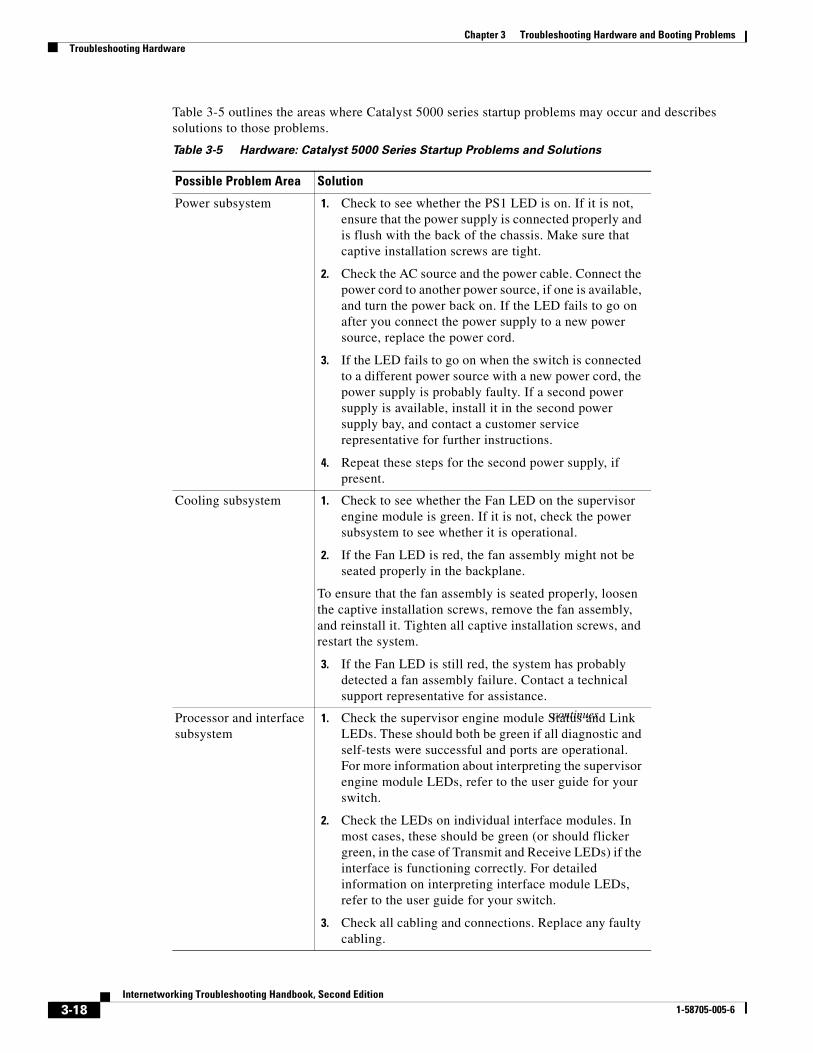
Table 3-5 outlines the areas where Catalyst 5000 series startup problems may occur and describes solutions to those problems.
Table 3-5 Hardware: Catalyst 5000 Series Startup Problems and Solutions
Possible Problem Area Solution
Power subsystem 1. Check to see whether the PS1 LED is on. If it is not, ensure that the power supply is connected properly and is flush with the back of the chassis. Make sure that captive installation screws are tight.
2. Check the AC source and the power cable. Connect the power cord to another power source, if one is available, and turn the power back on. If the LED fails to go on after you connect the power supply to a new power source, replace the power cord.
3. If the LED fails to go on when the switch is connected to a different power source with a new power cord, the power supply is probably faulty. If a second power supply is available, install it in the second power supply bay, and contact a customer service representative for further instructions.
4. Repeat these steps for the second power supply, if present.
Cooling subsystem 1. Check to see whether the Fan LED on the supervisor engine module is green. If it is not, check the power subsystem to see whether it is operational.
2. If the Fan LED is red, the fan assembly might not be seated properly in the backplane.
To ensure that the fan assembly is seated properly, loosen the captive installation screws, remove the fan assembly, and reinstall it. Tighten all captive installation screws, and restart the system.
3. If the Fan LED is still red, the system has probably detected a fan assembly failure. Contact a technical support representative for assistance.
Processor and interface subsystem
1. Check the supervisor engine module Status and Link LEDs. These should both be green if all diagnostic and self-tests were successful and ports are operational. For more information about interpreting the supervisor engine module LEDs, refer to the user guide for your switch.
2. Check the LEDs on individual interface modules. In most cases, these should be green (or should flicker green, in the case of Transmit and Receive LEDs) if the interface is functioning correctly. For detailed information on interpreting interface module LEDs, refer to the user guide for your switch.
3. Check all cabling and connections. Replace any faulty cabling.
continues
3-18Internetworking Troubleshooting Handbook, Second Edition
1-58705-005-6
Chapter 3 Troubleshooting Hardware and Booting ProblemsTroubleshooting Hardware
Catalyst 2900 Series StartupWhen you start up a Catalyst 2900 series LAN switch, the following should occur:
• The PS LED on the supervisor engine module faceplate should come on and stay green while power is applied to the system.
• The system fan assembly and Fan LED should come on and stay on while power is applied to the system.
• The Status LED on the supervisor engine module and on each interface should be orange until the boot is complete.
When the system boot is complete, the supervisor engine module initializes the switching modules. The status LED on each switching module goes on when initialization has been completed, and the console screen displays a script and system banner similar to the following:
BOOTROM Version 2.1, Dated May 22 1996 15:17:09
Boot date: 05/22/96 BOOT time: 15:17:09
Executing from RAM
Cisco Systems Console
Sending RARP request with address 00:40:0b:a0:05:b8
Sending bootp request with address 00:40:0b:a0:05:b8
Sending RARP request with address 00:40:0b:a0:05:b8
Sending bootp request with address 00:40:0b:a0:05:b8
No bootp or rarp response received
Enter password:
If problems occur, try to isolate the problem to a specific subsystem. The Catalyst 2900 series LAN switches have the following subsystems:
• Power subsystem—This subsystem includes the power supplies and power supply fans.
• Cooling subsystem—This subsystem includes the chassis fan assembly, which should be operating when the system power is on.
• Processor and interface subsystem—This subsystem includes the supervisor engine module (which contains the system operating software), the network interfaces, and all associated cabling.
3-19Internetworking Troubleshooting Handbook, Second Edition
1-58705-005-6

Chapter 3 Troubleshooting Hardware and Booting ProblemsTroubleshooting Hardware
Table 3-6 outlines the areas where Catalyst 2900 series startup problems may occur and describes solutions to those problems.
Testing and Verifying Replacement PartsIf you are replacing a part or card to remedy a suspected problem, make only one change at a time.
To test a system, start with a simple hardware configuration and add one card at a time until a failed interface appears or is isolated. Use a simple software configuration, and test connectivity using a ping test.
If you determine that a part or card replacement is required, contact your sales or technical support representative. Specific instructions concerning part or card installation are outlined in the configuration note provided with the replacement.
For modular routers, make sure that you seat all cards correctly. Check the seating of cards if the system is not booting properly. Use the ejector levers to reseat all processor modules, and then reboot.
Caution Before accessing the chassis interior and removing any cards, turn off power to the chassis. Use extreme caution around the chassis. Potentially harmful voltages are present.
Table 3-6 Hardware: Catalyst 2900 Series Startup Problems and Solutions
Possible Problem Area Solution
Power subsystem 1. Check the Power LED. If it is off, ensure that the power supply cord is not damaged and that it is properly attached to the power supply and to an AC receptacle.
2. If the LED is red, the power supply has detected an anomaly or voltage outage and needs to be serviced. Contact your technical support representative for instructions.
Cooling subsystem 1. Check to see whether the Fan LED on the supervisor engine module is green. If it is not, check the power subsystem to see whether it is operational.
2. If the Fan LED is red, contact a technical support representative for assistance.
Series processor and interface subsystem
1. Check the supervisor engine module Status and Link LEDs. These should both be green if all diagnostic and self-tests were successful and ports are operational. For more information about interpreting the supervisor engine module LEDs, refer to the user guide for your switch.
2. Check the LEDs on individual interface modules. In most cases, these should be green (or should flicker green, in the case of transmit and receive LEDs) if the interface is functioning correctly. For detailed information on interpreting interface module LEDs, refer to the user guide for your switch.
3. Check all cabling and connections. Replace any faulty cabling.
3-20Internetworking Troubleshooting Handbook, Second Edition
1-58705-005-6
Chapter 3 Troubleshooting Hardware and Booting ProblemsTroubleshooting Booting Problems
Caution To prevent damage to components that are sensitive to electrostatic discharge (ESD), attach ESD protection before opening a chassis. Make certain that the power cord is connected but that power is off. ESD damage prevention guidelines are provided in the hardware installation and maintenance publication for your router.
If a part replacement appears to solve a problem, reinstall the suspect part to verify the failure. Always double-check a repair.
Troubleshooting Booting ProblemsThis section discusses troubleshooting procedures for connectivity problems related to booting. It describes specific booting symptoms, the problems that are likely to cause each symptom, and the solutions to those problems.
Booting: Router Fails to Boot from Flash MemorySymptom: When a user is booting a router from Flash memory, the boot process appears to complete, but the router does not route traffic or communicate with neighbors. In addition, exec commands might or might not appear to function.
3-21Internetworking Troubleshooting Handbook, Second Edition
1-58705-005-6
Chapter 3 Troubleshooting Hardware and Booting ProblemsTroubleshooting Booting Problems
Table 3-7 outlines the problems that might cause this symptom and describes solutions to those problems.
3-22Internetworking Troubleshooting Handbook, Second Edition
1-58705-005-6
Chapter 3 Troubleshooting Hardware and Booting ProblemsTroubleshooting Booting Problems
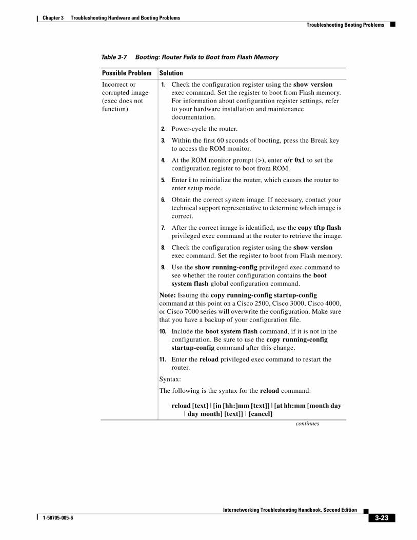
Table 3-7 Booting: Router Fails to Boot from Flash Memory
Possible Problem Solution
Incorrect or corrupted image (exec does not function)
1. Check the configuration register using the show version exec command. Set the register to boot from Flash memory. For information about configuration register settings, refer to your hardware installation and maintenance documentation.
2. Power-cycle the router.
3. Within the first 60 seconds of booting, press the Break key to access the ROM monitor.
4. At the ROM monitor prompt (>), enter o/r 0x1 to set the configuration register to boot from ROM.
5. Enter i to reinitialize the router, which causes the router to enter setup mode.
6. Obtain the correct system image. If necessary, contact your technical support representative to determine which image is correct.
7. After the correct image is identified, use the copy tftp flash privileged exec command at the router to retrieve the image.
8. Check the configuration register using the show version exec command. Set the register to boot from Flash memory.
9. Use the show running-config privileged exec command to see whether the router configuration contains the boot system flash global configuration command.
Note: Issuing the copy running-config startup-config command at this point on a Cisco 2500, Cisco 3000, Cisco 4000, or Cisco 7000 series will overwrite the configuration. Make sure that you have a backup of your configuration file.
10. Include the boot system flash command, if it is not in the configuration. Be sure to use the copy running-config startup-config command after this change.
11. Enter the reload privileged exec command to restart the router.
Syntax:
The following is the syntax for the reload command:
reload [text] | [in [hh:]mm [text]] | [at hh:mm [month day | day month] [text]] | [cancel]
continues
3-23Internetworking Troubleshooting Handbook, Second Edition
1-58705-005-6
Chapter 3 Troubleshooting Hardware and Booting ProblemsTroubleshooting Booting Problems
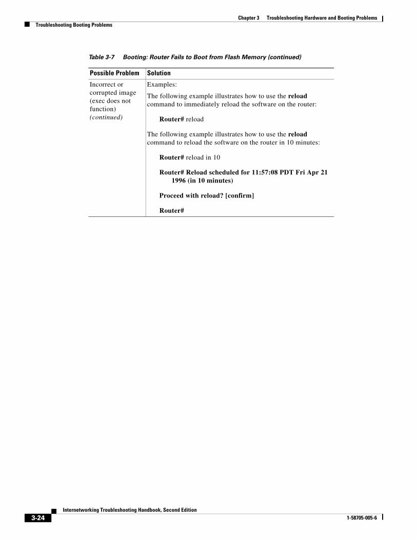
Incorrect or corrupted image (exec does not function) (continued)
Examples:
The following example illustrates how to use the reload command to immediately reload the software on the router:
Router# reload
The following example illustrates how to use the reload command to reload the software on the router in 10 minutes:
Router# reload in 10
Router# Reload scheduled for 11:57:08 PDT Fri Apr 21 1996 (in 10 minutes)
Proceed with reload? [confirm]
Router#
Table 3-7 Booting: Router Fails to Boot from Flash Memory (continued)
Possible Problem Solution
3-24Internetworking Troubleshooting Handbook, Second Edition
1-58705-005-6
Chapter 3 Troubleshooting Hardware and Booting ProblemsTroubleshooting Booting Problems
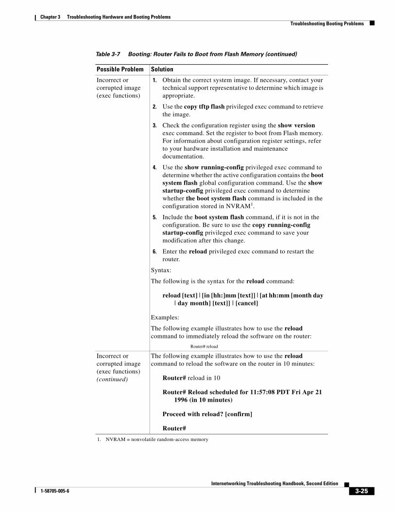
Incorrect or corrupted image (exec functions)
1. Obtain the correct system image. If necessary, contact your technical support representative to determine which image is appropriate.
2. Use the copy tftp flash privileged exec command to retrieve the image.
3. Check the configuration register using the show version exec command. Set the register to boot from Flash memory. For information about configuration register settings, refer to your hardware installation and maintenance documentation.
4. Use the show running-config privileged exec command to determine whether the active configuration contains the boot system flash global configuration command. Use the show startup-config privileged exec command to determine whether the boot system flash command is included in the configuration stored in NVRAM1.
5. Include the boot system flash command, if it is not in the configuration. Be sure to use the copy running-config startup-config privileged exec command to save your modification after this change.
6. Enter the reload privileged exec command to restart the router.
Syntax:
The following is the syntax for the reload command:
reload [text] | [in [hh:]mm [text]] | [at hh:mm [month day | day month] [text]] | [cancel]
Examples:
The following example illustrates how to use the reload command to immediately reload the software on the router:
Router# reload
Incorrect or corrupted image (exec functions) (continued)
The following example illustrates how to use the reload command to reload the software on the router in 10 minutes:
Router# reload in 10
Router# Reload scheduled for 11:57:08 PDT Fri Apr 21 1996 (in 10 minutes)
Proceed with reload? [confirm]
Router#
1. NVRAM = nonvolatile random-access memory
Table 3-7 Booting: Router Fails to Boot from Flash Memory (continued)
Possible Problem Solution
3-25Internetworking Troubleshooting Handbook, Second Edition
1-58705-005-6

Chapter 3 Troubleshooting Hardware and Booting ProblemsTroubleshooting Booting Problems
Booting: Vector Error Occurs When Booting from Flash MemorySymptom: Vector errors occur when a user is booting a router from Flash memory.
3-26Internetworking Troubleshooting Handbook, Second Edition
1-58705-005-6
Chapter 3 Troubleshooting Hardware and Booting ProblemsTroubleshooting Booting Problems
Table 3-8 outlines the problems that might cause this symptom and describes solutions to those problems.
3-27Internetworking Troubleshooting Handbook, Second Edition
1-58705-005-6
Chapter 3 Troubleshooting Hardware and Booting ProblemsTroubleshooting Booting Problems
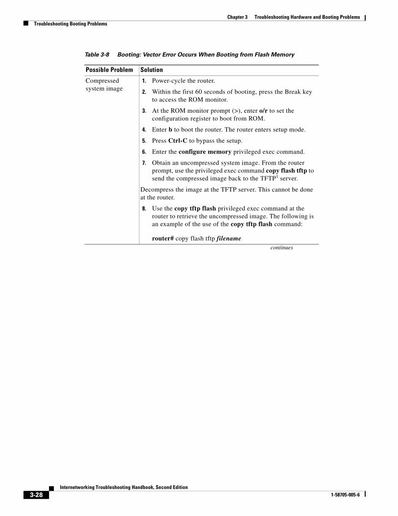
Table 3-8 Booting: Vector Error Occurs When Booting from Flash Memory
Possible Problem Solution
Compressed system image
1. Power-cycle the router.
2. Within the first 60 seconds of booting, press the Break key to access the ROM monitor.
3. At the ROM monitor prompt (>), enter o/r to set the configuration register to boot from ROM.
4. Enter b to boot the router. The router enters setup mode.
5. Press Ctrl-C to bypass the setup.
6. Enter the configure memory privileged exec command.
7. Obtain an uncompressed system image. From the router prompt, use the privileged exec command copy flash tftp to send the compressed image back to the TFTP1 server.
Decompress the image at the TFTP server. This cannot be done at the router.
8. Use the copy tftp flash privileged exec command at the router to retrieve the uncompressed image. The following is an example of the use of the copy tftp flash command:
router# copy flash tftp filenamecontinues
3-28Internetworking Troubleshooting Handbook, Second Edition
1-58705-005-6

Chapter 3 Troubleshooting Hardware and Booting ProblemsTroubleshooting Booting Problems
Compressed system image (continued)
The router asks you for the IP address of the TFTP server and the name of the image file that you are copying to the server. A sample of the output for this command using IP address 131.108.10.6 and filename ic92130n follows:
IP address of remote host [255.255.255.255]? 131.108.10.6
Name of file to copy []? ic92130n
writing ic92130n !!!!!!!!!!!!!!!!!!!!!!!!!!!!!!!!!!!!!!!!!!!
router#
9. Check the configuration register using the show version exec command. Set the router to boot from Flash memory.
10. Use the show running-config privileged exec command to determine whether the router configuration includes the boot system flash global configuration command in the correct order with respect to the other boot system commands.
Note: The boot system global configuration commands are saved in the order in which they were entered. The most recent entry goes to the bottom of the list. For the recommended ordering, refer to the section "Fault-Tolerant Boot Strategies," earlier in this chapter.
11. Configure the boot system flash command, if it is missing. Confirm that the order of boot system commands is correct. Use the copy running-config startup-config command to save this change. The required syntax is as follows:
copy running-config {rcp | startup-config | tftp | file-id} (Cisco 7000, Cisco 7200, and Cisco 7500 series only)
Syntax description:
rcp—Specifies a copy operation to a network server using RCP.
startup-config—Specifies the configuration used for initialization as the destination of the copy operation. The Cisco 4500 series cannot use this keyword.
tftp—Specifies a TFTP server as the destination of the copy operation.
file-id—Specifies device:filename as the destination of the copy operation. The device argument is optional, but when it is used, the colon (:) is required.
12. Enter the reload privileged exec command to restart the router.
Table 3-8 Booting: Vector Error Occurs When Booting from Flash Memory (continued)
Possible Problem Solution
3-29Internetworking Troubleshooting Handbook, Second Edition
1-58705-005-6
Chapter 3 Troubleshooting Hardware and Booting ProblemsTroubleshooting Booting Problems
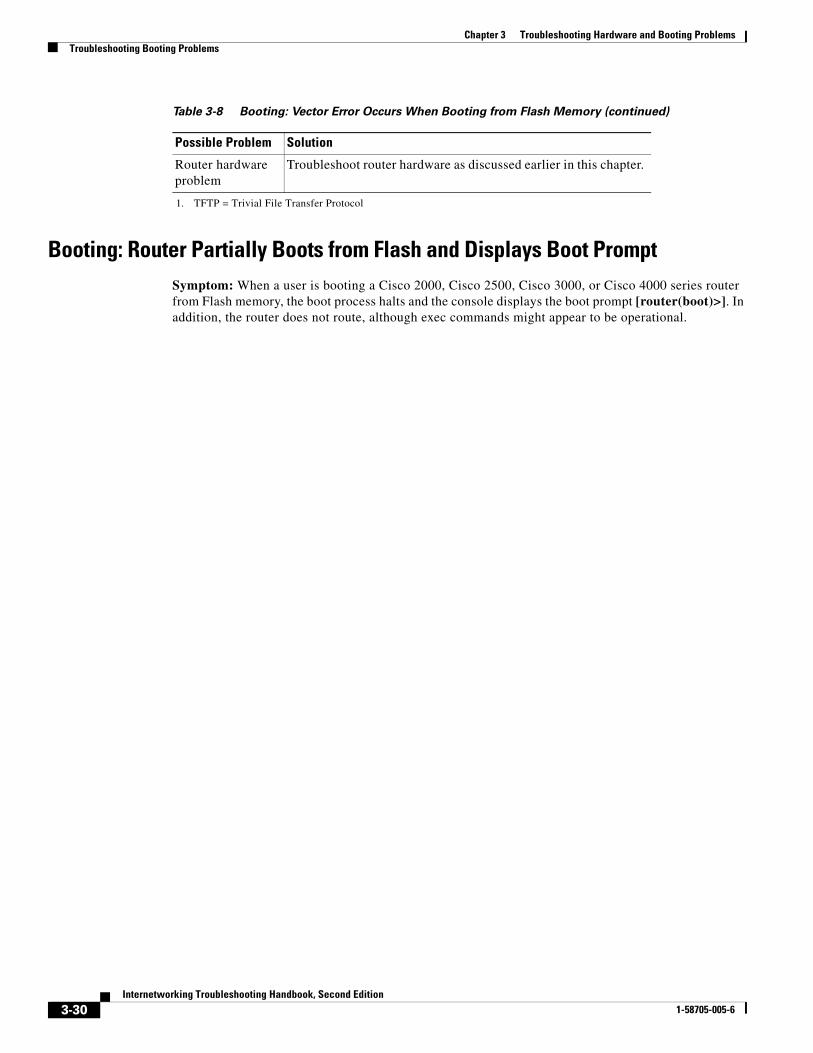
Booting: Router Partially Boots from Flash and Displays Boot PromptSymptom: When a user is booting a Cisco 2000, Cisco 2500, Cisco 3000, or Cisco 4000 series router from Flash memory, the boot process halts and the console displays the boot prompt [router(boot)>]. In addition, the router does not route, although exec commands might appear to be operational.
Router hardware problem
Troubleshoot router hardware as discussed earlier in this chapter.
1. TFTP = Trivial File Transfer Protocol
Table 3-8 Booting: Vector Error Occurs When Booting from Flash Memory (continued)
Possible Problem Solution
3-30Internetworking Troubleshooting Handbook, Second Edition
1-58705-005-6
Chapter 3 Troubleshooting Hardware and Booting ProblemsTroubleshooting Booting Problems
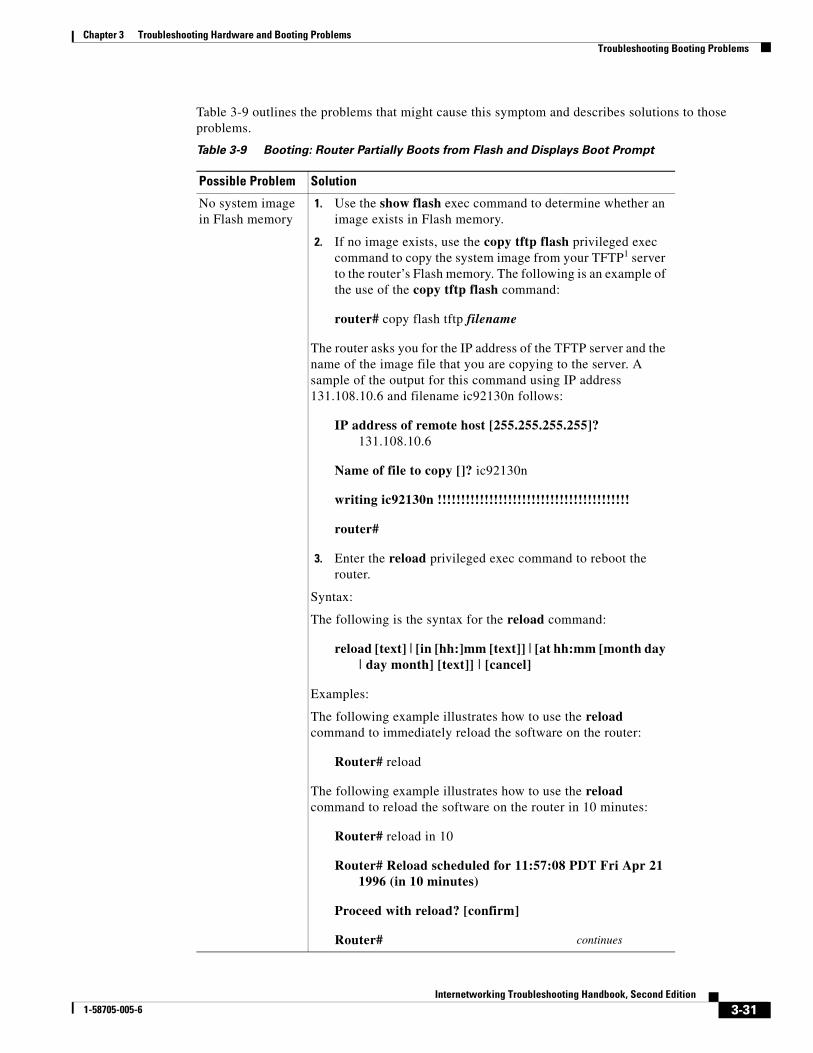
Table 3-9 outlines the problems that might cause this symptom and describes solutions to those problems.
Table 3-9 Booting: Router Partially Boots from Flash and Displays Boot Prompt
Possible Problem Solution
No system image in Flash memory
1. Use the show flash exec command to determine whether an image exists in Flash memory.
2. If no image exists, use the copy tftp flash privileged exec command to copy the system image from your TFTP1 server to the router’s Flash memory. The following is an example of the use of the copy tftp flash command:
router# copy flash tftp filename
The router asks you for the IP address of the TFTP server and the name of the image file that you are copying to the server. A sample of the output for this command using IP address 131.108.10.6 and filename ic92130n follows:
IP address of remote host [255.255.255.255]? 131.108.10.6
Name of file to copy []? ic92130n
writing ic92130n !!!!!!!!!!!!!!!!!!!!!!!!!!!!!!!!!!!!!!!!!
router#
3. Enter the reload privileged exec command to reboot the router.
Syntax:
The following is the syntax for the reload command:
reload [text] | [in [hh:]mm [text]] | [at hh:mm [month day | day month] [text]] | [cancel]
Examples:
The following example illustrates how to use the reload command to immediately reload the software on the router:
Router# reload
The following example illustrates how to use the reload command to reload the software on the router in 10 minutes:
Router# reload in 10
Router# Reload scheduled for 11:57:08 PDT Fri Apr 21 1996 (in 10 minutes)
Proceed with reload? [confirm]
Router# continues
3-31Internetworking Troubleshooting Handbook, Second Edition
1-58705-005-6
Chapter 3 Troubleshooting Hardware and Booting ProblemsTroubleshooting Booting Problems
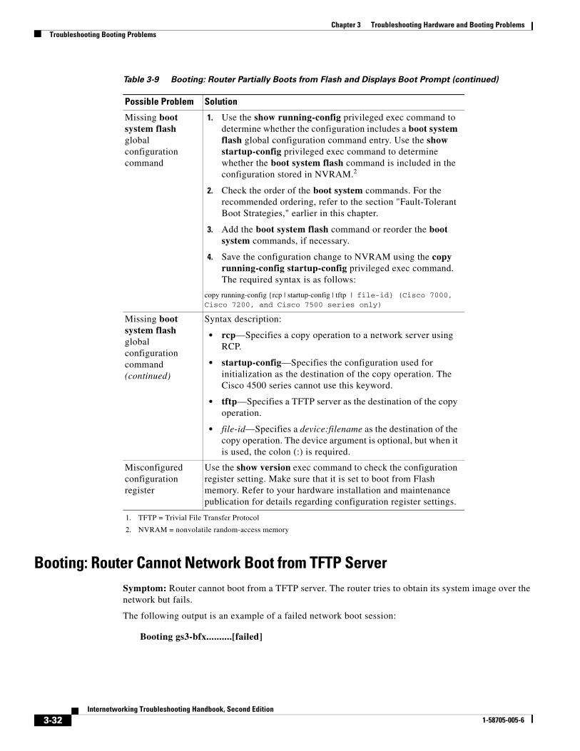
Booting: Router Cannot Network Boot from TFTP ServerSymptom: Router cannot boot from a TFTP server. The router tries to obtain its system image over the network but fails.
The following output is an example of a failed network boot session:
Booting gs3-bfx..........[failed]
Missing boot system flash global configuration command
1. Use the show running-config privileged exec command to determine whether the configuration includes a boot system flash global configuration command entry. Use the show startup-config privileged exec command to determine whether the boot system flash command is included in the configuration stored in NVRAM.2
2. Check the order of the boot system commands. For the recommended ordering, refer to the section "Fault-Tolerant Boot Strategies," earlier in this chapter.
3. Add the boot system flash command or reorder the boot system commands, if necessary.
4. Save the configuration change to NVRAM using the copy running-config startup-config privileged exec command. The required syntax is as follows:
copy running-config {rcp | startup-config | tftp | file-id} (Cisco 7000, Cisco 7200, and Cisco 7500 series only)
Missing boot system flash global configuration command (continued)
Syntax description:
• rcp—Specifies a copy operation to a network server using RCP.
• startup-config—Specifies the configuration used for initialization as the destination of the copy operation. The Cisco 4500 series cannot use this keyword.
• tftp—Specifies a TFTP server as the destination of the copy operation.
• file-id—Specifies a device:filename as the destination of the copy operation. The device argument is optional, but when it is used, the colon (:) is required.
Misconfigured configuration register
Use the show version exec command to check the configuration register setting. Make sure that it is set to boot from Flash memory. Refer to your hardware installation and maintenance publication for details regarding configuration register settings.
1. TFTP = Trivial File Transfer Protocol
2. NVRAM = nonvolatile random-access memory
Table 3-9 Booting: Router Partially Boots from Flash and Displays Boot Prompt (continued)
Possible Problem Solution
3-32Internetworking Troubleshooting Handbook, Second Edition
1-58705-005-6
Chapter 3 Troubleshooting Hardware and Booting ProblemsTroubleshooting Booting Problems
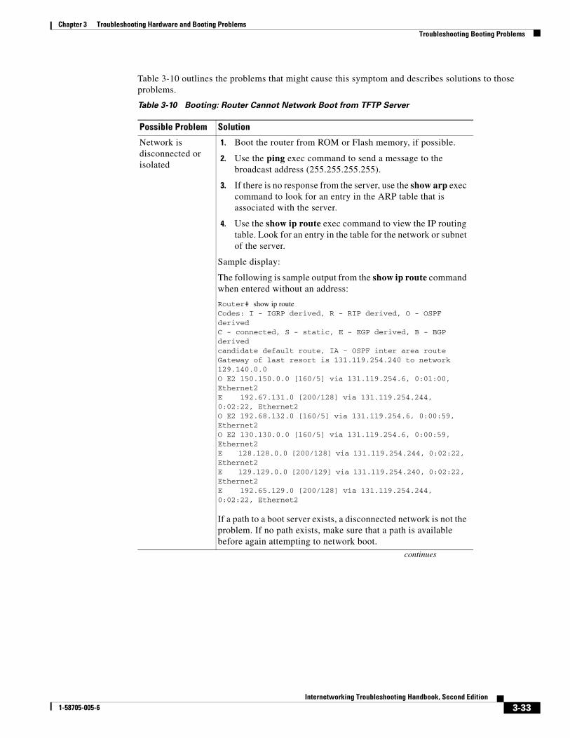
Table 3-10 outlines the problems that might cause this symptom and describes solutions to those problems.
Table 3-10 Booting: Router Cannot Network Boot from TFTP Server
Possible Problem Solution
Network is disconnected or isolated
1. Boot the router from ROM or Flash memory, if possible.
2. Use the ping exec command to send a message to the broadcast address (255.255.255.255).
3. If there is no response from the server, use the show arp exec command to look for an entry in the ARP table that is associated with the server.
4. Use the show ip route exec command to view the IP routing table. Look for an entry in the table for the network or subnet of the server.
Sample display:
The following is sample output from the show ip route command when entered without an address:
Router# show ip routeCodes: I - IGRP derived, R - RIP derived, O - OSPF derivedC - connected, S - static, E - EGP derived, B - BGP derivedcandidate default route, IA - OSPF inter area routeGateway of last resort is 131.119.254.240 to network 129.140.0.0O E2 150.150.0.0 [160/5] via 131.119.254.6, 0:01:00, Ethernet2E 192.67.131.0 [200/128] via 131.119.254.244, 0:02:22, Ethernet2O E2 192.68.132.0 [160/5] via 131.119.254.6, 0:00:59, Ethernet2O E2 130.130.0.0 [160/5] via 131.119.254.6, 0:00:59, Ethernet2E 128.128.0.0 [200/128] via 131.119.254.244, 0:02:22, Ethernet2E 129.129.0.0 [200/129] via 131.119.254.240, 0:02:22, Ethernet2E 192.65.129.0 [200/128] via 131.119.254.244, 0:02:22, Ethernet2
If a path to a boot server exists, a disconnected network is not the problem. If no path exists, make sure that a path is available before again attempting to network boot.
continues
3-33Internetworking Troubleshooting Handbook, Second Edition
1-58705-005-6
Chapter 3 Troubleshooting Hardware and Booting ProblemsTroubleshooting Booting Problems
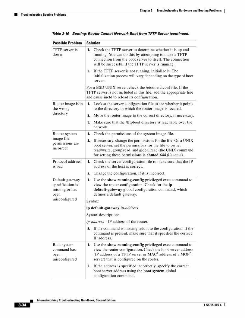
TFTP server is down
1. Check the TFTP server to determine whether it is up and running. You can do this by attempting to make a TFTP connection from the boot server to itself. The connection will be successful if the TFTP server is running.
2. If the TFTP server is not running, initialize it. The initialization process will vary depending on the type of boot server.
For a BSD UNIX server, check the /etc/inetd.conf file. If the TFTP server is not included in this file, add the appropriate line and cause inetd to reload its configuration.
Router image is in the wrong directory
1. Look at the server configuration file to see whether it points to the directory in which the router image is located.
2. Move the router image to the correct directory, if necessary.
3. Make sure that the /tftpboot directory is reachable over the network.
Router system image file permissions are incorrect
1. Check the permissions of the system image file.
2. If necessary, change the permissions for the file. On a UNIX boot server, set the permissions for the file to owner read/write, group read, and global read (the UNIX command for setting these permissions is chmod 644 filename).
Protocol address is bad
1. Check the server configuration file to make sure that the IP address of the host is correct.
2. Change the configuration, if it is incorrect.
Default gateway specification is missing or has been misconfigured
1. Use the show running-config privileged exec command to view the router configuration. Check for the ip default-gateway global configuration command, which defines a default gateway.
Syntax:
ip default-gateway ip-address
Syntax description:
ip-address—IP address of the router.
2. If the command is missing, add it to the configuration. If the command is present, make sure that it specifies the correct IP address.
Boot system command has been misconfigured
1. Use the show running-config privileged exec command to view the router configuration. Check the boot server address (IP address of a TFTP server or MAC1 address of a MOP2 server) that is configured on the router.
2. If the address is specified incorrectly, specify the correct boot server address using the boot system global configuration command.
Table 3-10 Booting: Router Cannot Network Boot from TFTP Server (continued)
Possible Problem Solution
3-34Internetworking Troubleshooting Handbook, Second Edition
1-58705-005-6
Chapter 3 Troubleshooting Hardware and Booting ProblemsTroubleshooting Booting Problems
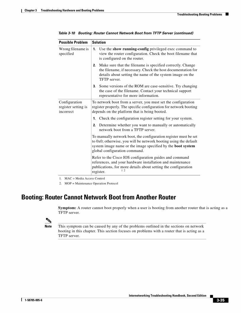
Booting: Router Cannot Network Boot from Another RouterSymptom: A router cannot boot properly when a user is booting from another router that is acting as a TFTP server.
Note This symptom can be caused by any of the problems outlined in the sections on network booting in this chapter. This section focuses on problems with a router that is acting as a TFTP server.
Wrong filename is specified
1. Use the show running-config privileged exec command to view the router configuration. Check the boot filename that is configured on the router.
2. Make sure that the filename is specified correctly. Change the filename, if necessary. Check the host documentation for details about setting the name of the system image on the TFTP server.
3. Some versions of the ROM are case-sensitive. Try changing the case of the filename. Contact your technical support representative for more information.
Configuration register setting is incorrect
To network boot from a server, you must set the configuration register properly. The specific configuration for network booting depends on the platform that is being booted.
1. Check the configuration register setting for your system.
2. Determine whether you want to manually or automatically network boot from a TFTP server.
To manually network boot, the configuration register must be set to 0x0; otherwise, you will be network booting using the default system image name or the image specified by the boot system global configuration command.
Refer to the Cisco IOS configuration guides and command references, and your hardware installation and maintenance publications, for more details about setting the configuration register. 1 2
1. MAC = Media Access Control
2. MOP = Maintenance Operation Protocol
Table 3-10 Booting: Router Cannot Network Boot from TFTP Server (continued)
Possible Problem Solution
3-35Internetworking Troubleshooting Handbook, Second Edition
1-58705-005-6
Chapter 3 Troubleshooting Hardware and Booting ProblemsTroubleshooting Booting Problems
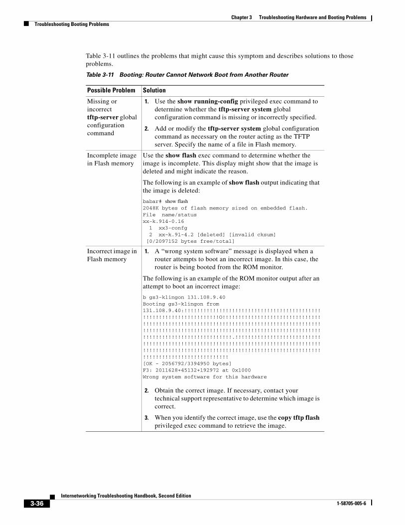
Table 3-11 outlines the problems that might cause this symptom and describes solutions to those problems.
Table 3-11 Booting: Router Cannot Network Boot from Another Router
Possible Problem Solution
Missing or incorrect tftp-server global configuration command
1. Use the show running-config privileged exec command to determine whether the tftp-server system global configuration command is missing or incorrectly specified.
2. Add or modify the tftp-server system global configuration command as necessary on the router acting as the TFTP server. Specify the name of a file in Flash memory.
Incomplete image in Flash memory
Use the show flash exec command to determine whether the image is incomplete. This display might show that the image is deleted and might indicate the reason.
The following is an example of show flash output indicating that the image is deleted:
babar# show flash2048K bytes of flash memory sized on embedded flash.File name/statusxx-k.914-0.16 1 xx3-confg 2 xx-k.91-4.2 [deleted] [invalid cksum] [0/2097152 bytes free/total]
Incorrect image in Flash memory
1. A “wrong system software” message is displayed when a router attempts to boot an incorrect image. In this case, the router is being booted from the ROM monitor.
The following is an example of the ROM monitor output after an attempt to boot an incorrect image:
b gs3-klingon 131.108.9.40Booting gs3-klingon from 131.108.9.40:!!!!!!!!!!!!!!!!!!!!!!!!!!!!!!!!!!!!!!!!!!!!!!!!!!!!!!!!!!!!!!!!!!!O!!!!!!!!!!!!!!!!!!!!!!!!!!!!!!!!!!!!!!!!!!!!!!!!!!!!!!!!!!!!!!!!!!!!!!!!!!!!!!!!!!!!!!!!!!!!!!!!!!!!!!!!!!!!!!!!!!!!!!!!!!!!!!!!!!!!!!!!!!!!!!!!!!!!!!!!!!!!!!!!!!!!!!!!!!!.!!!!!!!!!!!!!!!!!!!!!!!!!!!!!!!!!!!!!!!!!!!!!!!!!!!!!!!!!!!!!!!!!!!!!!!!!!!!!!!!!!!!!!!!!!!!!!!!!!!!!!!!!!!!!!!!!!!!!!!!!!!!!!!!!!!!!!!!!!!!!!!!!!!!!!!!!!!!!!!!!!!!!![OK - 2056792/3394950 bytes] F3: 2011628+45132+192972 at 0x1000Wrong system software for this hardware
2. Obtain the correct image. If necessary, contact your technical support representative to determine which image is correct.
3. When you identify the correct image, use the copy tftp flash privileged exec command to retrieve the image.
3-36Internetworking Troubleshooting Handbook, Second Edition
1-58705-005-6

Chapter 3 Troubleshooting Hardware and Booting ProblemsTroubleshooting Booting Problems
Booting: Timeouts and Out-of-Order Packets Prevent Network BootingSymptom: Timeouts or out-of-order packets prevent successful network booting. The number of timeouts and out-of-order packets indicated on the router’s console display might vary.
The following example shows a network booting session that contains excessive timeouts and out-of-order packets:
Booting gs3-bfx from 131.108.1.123: !O.O!.O..O!!!OOO.O!!.O.O.....
The client router might boot in this situation. However, when excessive timeouts and out-of-order packets occur, there is probably a network problem, and network booting (as well as network service availability) might be inconsistent.
Table 3-12 outlines the problems that might cause this symptom and describes solutions to those problems.
Booting: Invalid Routes Prevent Network BootingSymptom: Invalid routes prevent successful network booting. If the router is sending packets over an invalid path, a message similar to one of the following is displayed on the console:
Booting gs3-bfx!OOOO..........[timed out]
Booting gs3-bfx!.O.O.O.O..........[timed out]
Booting gs3-bfx!!!!!!!!!!OOOOOOOOOO..........[timed out]
Table 3-12 Booting: Timeouts and Out-of-Order Packets Prevent Network Booting
Possible Problem Solution
Link is saturated 1. Boot the router from ROM and ping the TFTP server. Determine whether timeouts and out-of-order packets appear.
2. Check local network concentrators for excessive collisions on the same network. If there are excessive collisions, reorganizing your network topology might help reduce collisions.
3. Use the show interfaces exec command on routers in the path, or place a network analyzer between the router and server. Look for dropped packets and output errors.
4. If approximately 15 percent or more of the traffic is being dropped, or if any output errors occur, congestion might be the problem.
5. Wait until the traffic subsides before attempting to network boot the router. If the problem is chronic, increase bandwidth or move the server closer to the router being booted.
Link is down 1. Check the continuity of the path from the booting router to the boot server using ping or trace exec commands.
2. If a break is found, restore the link and attempt to network boot again.
3-37Internetworking Troubleshooting Handbook, Second Edition
1-58705-005-6
Chapter 3 Troubleshooting Hardware and Booting ProblemsTroubleshooting Booting Problems
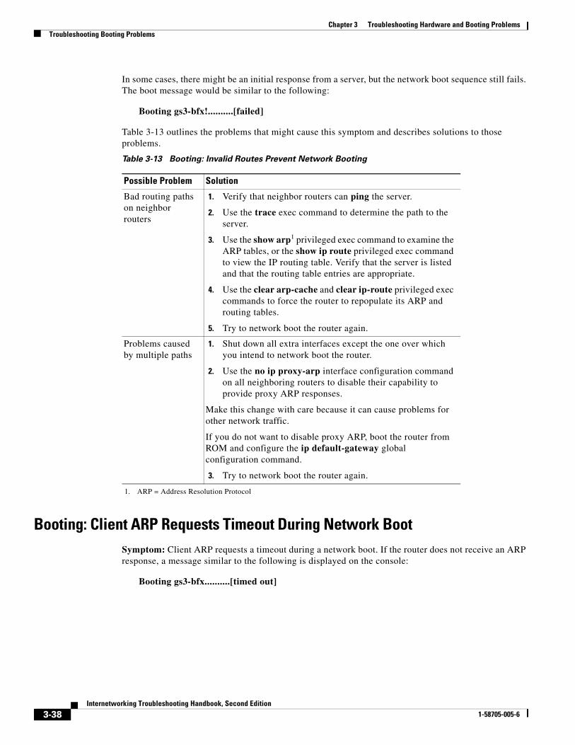
In some cases, there might be an initial response from a server, but the network boot sequence still fails. The boot message would be similar to the following:
Booting gs3-bfx!..........[failed]
Table 3-13 outlines the problems that might cause this symptom and describes solutions to those problems.
Booting: Client ARP Requests Timeout During Network BootSymptom: Client ARP requests a timeout during a network boot. If the router does not receive an ARP response, a message similar to the following is displayed on the console:
Booting gs3-bfx..........[timed out]
Table 3-13 Booting: Invalid Routes Prevent Network Booting
Possible Problem Solution
Bad routing paths on neighbor routers
1. Verify that neighbor routers can ping the server.
2. Use the trace exec command to determine the path to the server.
3. Use the show arp1 privileged exec command to examine the ARP tables, or the show ip route privileged exec command to view the IP routing table. Verify that the server is listed and that the routing table entries are appropriate.
4. Use the clear arp-cache and clear ip-route privileged exec commands to force the router to repopulate its ARP and routing tables.
5. Try to network boot the router again.
Problems caused by multiple paths
1. Shut down all extra interfaces except the one over which you intend to network boot the router.
2. Use the no ip proxy-arp interface configuration command on all neighboring routers to disable their capability to provide proxy ARP responses.
Make this change with care because it can cause problems for other network traffic.
If you do not want to disable proxy ARP, boot the router from ROM and configure the ip default-gateway global configuration command.
3. Try to network boot the router again.
1. ARP = Address Resolution Protocol
3-38Internetworking Troubleshooting Handbook, Second Edition
1-58705-005-6

Chapter 3 Troubleshooting Hardware and Booting ProblemsTroubleshooting Booting Problems
Table 3-14 outlines the problems that might cause this symptom and describes solutions to those problems.
3-39Internetworking Troubleshooting Handbook, Second Edition
1-58705-005-6
Chapter 3 Troubleshooting Hardware and Booting ProblemsTroubleshooting Booting Problems
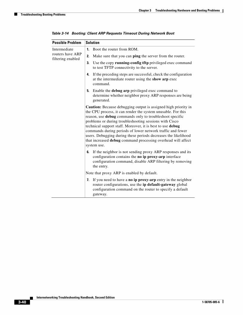
Table 3-14 Booting: Client ARP Requests Timeout During Network Boot
Possible Problem Solution
Intermediate routers have ARP filtering enabled
1. Boot the router from ROM.
2. Make sure that you can ping the server from the router.
3. Use the copy running-config tftp privileged exec command to test TFTP connectivity to the server.
4. If the preceding steps are successful, check the configuration at the intermediate router using the show arp exec command.
5. Enable the debug arp privileged exec command to determine whether neighbor proxy ARP responses are being generated.
Caution: Because debugging output is assigned high priority in the CPU process, it can render the system unusable. For this reason, use debug commands only to troubleshoot specific problems or during troubleshooting sessions with Cisco technical support staff. Moreover, it is best to use debug commands during periods of lower network traffic and fewer users. Debugging during these periods decreases the likelihood that increased debug command processing overhead will affect system use.
6. If the neighbor is not sending proxy ARP responses and its configuration contains the no ip proxy-arp interface configuration command, disable ARP filtering by removing the entry.
Note that proxy ARP is enabled by default.
7. If you need to have a no ip proxy-arp entry in the neighbor router configurations, use the ip default-gateway global configuration command on the router to specify a default gateway.
3-40Internetworking Troubleshooting Handbook, Second Edition
1-58705-005-6
Chapter 3 Troubleshooting Hardware and Booting ProblemsTroubleshooting Booting Problems
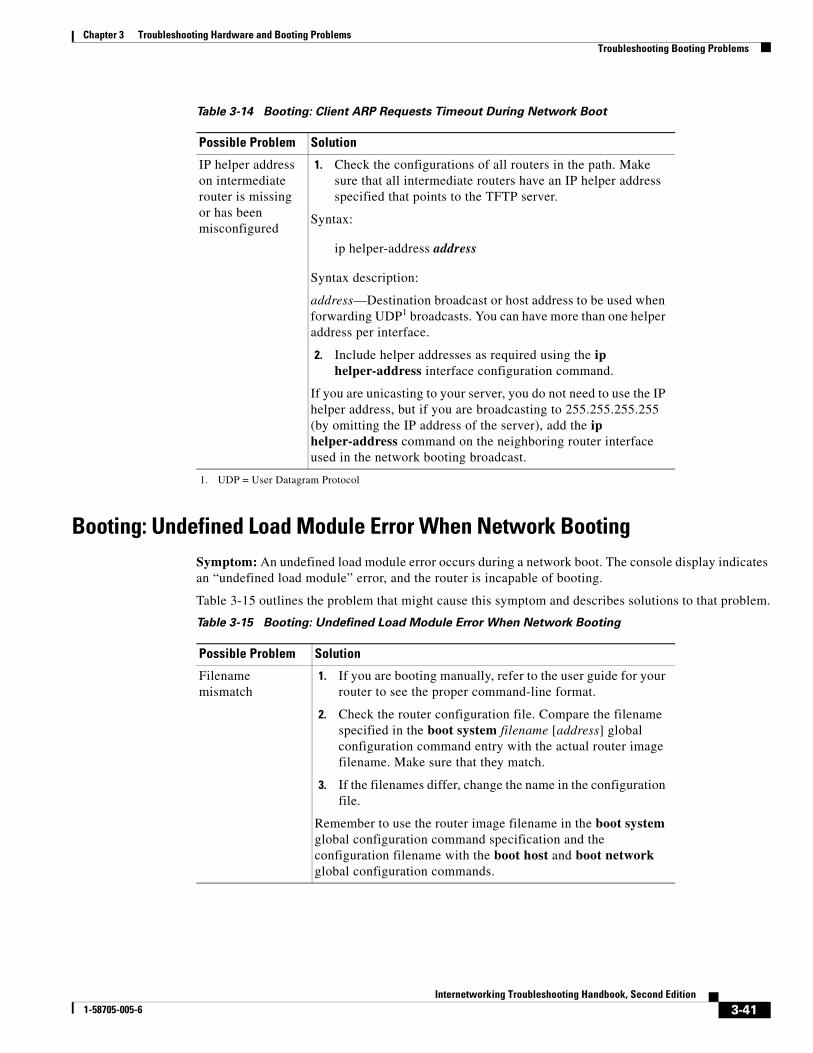
Booting: Undefined Load Module Error When Network BootingSymptom: An undefined load module error occurs during a network boot. The console display indicates an “undefined load module” error, and the router is incapable of booting.
Table 3-15 outlines the problem that might cause this symptom and describes solutions to that problem.
IP helper address on intermediate router is missing or has been misconfigured
1. Check the configurations of all routers in the path. Make sure that all intermediate routers have an IP helper address specified that points to the TFTP server.
Syntax:
ip helper-address address
Syntax description:
address—Destination broadcast or host address to be used when forwarding UDP1 broadcasts. You can have more than one helper address per interface.
2. Include helper addresses as required using the ip helper-address interface configuration command.
If you are unicasting to your server, you do not need to use the IP helper address, but if you are broadcasting to 255.255.255.255 (by omitting the IP address of the server), add the ip helper-address command on the neighboring router interface used in the network booting broadcast.
1. UDP = User Datagram Protocol
Table 3-14 Booting: Client ARP Requests Timeout During Network Boot
Possible Problem Solution
Table 3-15 Booting: Undefined Load Module Error When Network Booting
Possible Problem Solution
Filename mismatch
1. If you are booting manually, refer to the user guide for your router to see the proper command-line format.
2. Check the router configuration file. Compare the filename specified in the boot system filename [address] global configuration command entry with the actual router image filename. Make sure that they match.
3. If the filenames differ, change the name in the configuration file.
Remember to use the router image filename in the boot system global configuration command specification and the configuration filename with the boot host and boot network global configuration commands.
3-41Internetworking Troubleshooting Handbook, Second Edition
1-58705-005-6
Chapter 3 Troubleshooting Hardware and Booting ProblemsTroubleshooting Booting Problems
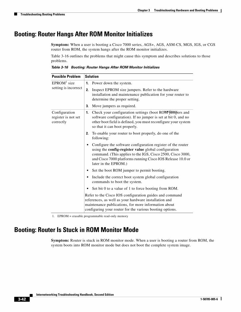
Booting: Router Hangs After ROM Monitor InitializesSymptom: When a user is booting a Cisco 7000 series, AGS+, AGS, ASM-CS, MGS, IGS, or CGS router from ROM, the system hangs after the ROM monitor initializes.
Table 3-16 outlines the problems that might cause this symptom and describes solutions to those problems.
Booting: Router Is Stuck in ROM Monitor ModeSymptom: Router is stuck in ROM monitor mode. When a user is booting a router from ROM, the system boots into ROM monitor mode but does not boot the complete system image.
Table 3-16 Booting: Router Hangs After ROM Monitor Initializes
Possible Problem Solution
EPROM1 size setting is incorrect
1. Power down the system.
2. Inspect EPROM size jumpers. Refer to the hardware installation and maintenance publication for your router to determine the proper setting.
3. Move jumpers as required.
Configuration register is not set correctly
1. Check your configuration settings (boot ROM jumpers and software configuration). If no jumper is set at bit 0, and no other boot field is defined, you must reconfigure your system so that it can boot properly.
2. To enable your router to boot properly, do one of the following:
• Configure the software configuration register of the router using the config-register value global configuration command. (This applies to the IGS, Cisco 2500, Cisco 3000, and Cisco 7000 platforms running Cisco IOS Release 10.0 or later in the EPROM.)
• Set the boot ROM jumper to permit booting.
• Include the correct boot system global configuration commands to boot the system.
• Set bit 0 to a value of 1 to force booting from ROM.
Refer to the Cisco IOS configuration guides and command references, as well as your hardware installation and maintenance publications, for more information about configuring your router for the various booting options.
1. EPROM = erasable programmable read-only memory
continues
3-42Internetworking Troubleshooting Handbook, Second Edition
1-58705-005-6
Chapter 3 Troubleshooting Hardware and Booting ProblemsTroubleshooting Booting Problems
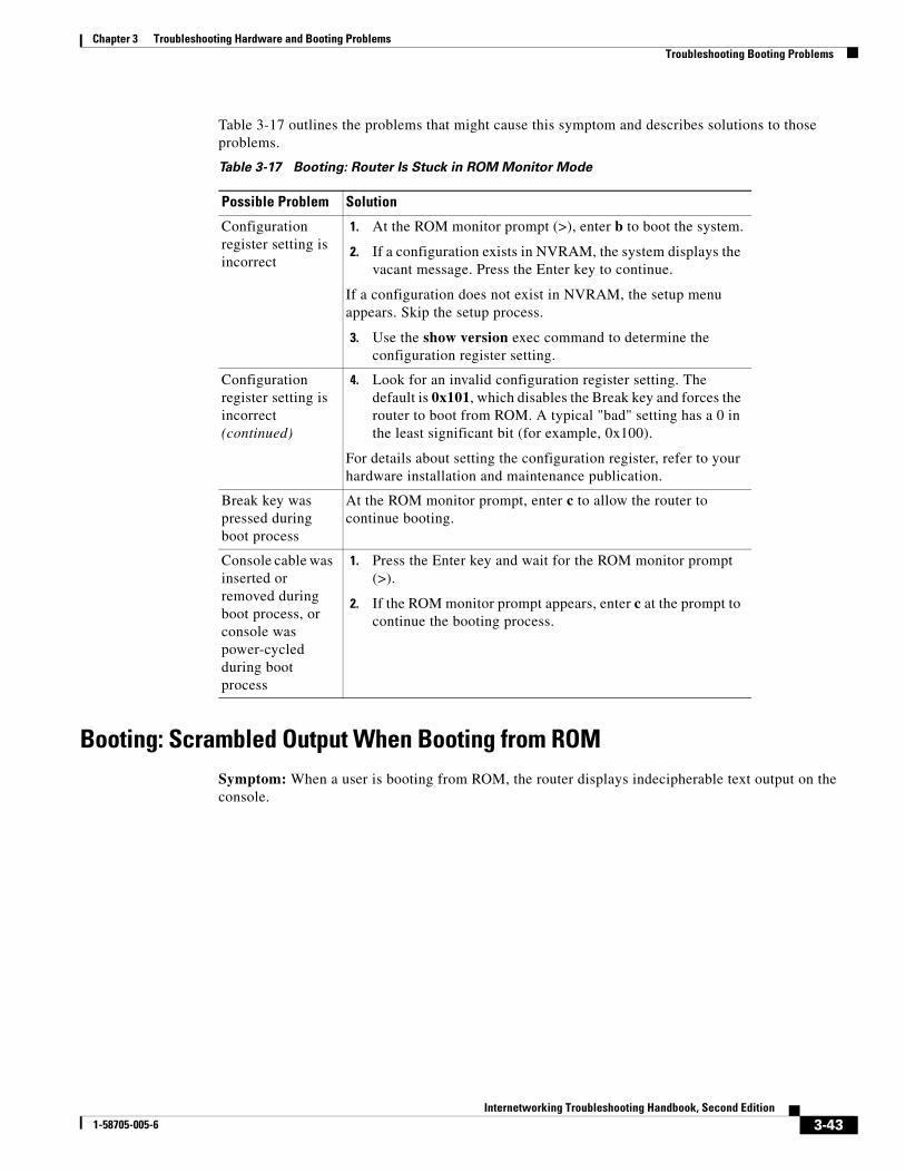
Table 3-17 outlines the problems that might cause this symptom and describes solutions to those problems.
Booting: Scrambled Output When Booting from ROMSymptom: When a user is booting from ROM, the router displays indecipherable text output on the console.
Table 3-17 Booting: Router Is Stuck in ROM Monitor Mode
Possible Problem Solution
Configuration register setting is incorrect
1. At the ROM monitor prompt (>), enter b to boot the system.
2. If a configuration exists in NVRAM, the system displays the vacant message. Press the Enter key to continue.
If a configuration does not exist in NVRAM, the setup menu appears. Skip the setup process.
3. Use the show version exec command to determine the configuration register setting.
Configuration register setting is incorrect (continued)
4. Look for an invalid configuration register setting. The default is 0x101, which disables the Break key and forces the router to boot from ROM. A typical "bad" setting has a 0 in the least significant bit (for example, 0x100).
For details about setting the configuration register, refer to your hardware installation and maintenance publication.
Break key was pressed during boot process
At the ROM monitor prompt, enter c to allow the router to continue booting.
Console cable was inserted or removed during boot process, or console was power-cycled during boot process
1. Press the Enter key and wait for the ROM monitor prompt (>).
2. If the ROM monitor prompt appears, enter c at the prompt to continue the booting process.
3-43Internetworking Troubleshooting Handbook, Second Edition
1-58705-005-6
Chapter 3 Troubleshooting Hardware and Booting ProblemsTroubleshooting Booting Problems
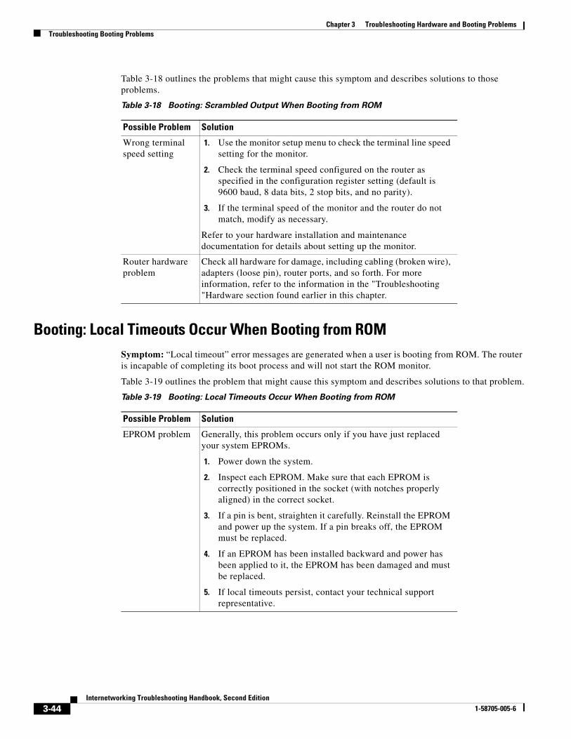
Table 3-18 outlines the problems that might cause this symptom and describes solutions to those problems.
Booting: Local Timeouts Occur When Booting from ROMSymptom: “Local timeout” error messages are generated when a user is booting from ROM. The router is incapable of completing its boot process and will not start the ROM monitor.
Table 3-19 outlines the problem that might cause this symptom and describes solutions to that problem.
Table 3-18 Booting: Scrambled Output When Booting from ROM
Possible Problem Solution
Wrong terminal speed setting
1. Use the monitor setup menu to check the terminal line speed setting for the monitor.
2. Check the terminal speed configured on the router as specified in the configuration register setting (default is 9600 baud, 8 data bits, 2 stop bits, and no parity).
3. If the terminal speed of the monitor and the router do not match, modify as necessary.
Refer to your hardware installation and maintenance documentation for details about setting up the monitor.
Router hardware problem
Check all hardware for damage, including cabling (broken wire), adapters (loose pin), router ports, and so forth. For more information, refer to the information in the "Troubleshooting "Hardware section found earlier in this chapter.
Table 3-19 Booting: Local Timeouts Occur When Booting from ROM
Possible Problem Solution
EPROM problem Generally, this problem occurs only if you have just replaced your system EPROMs.
1. Power down the system.
2. Inspect each EPROM. Make sure that each EPROM is correctly positioned in the socket (with notches properly aligned) in the correct socket.
3. If a pin is bent, straighten it carefully. Reinstall the EPROM and power up the system. If a pin breaks off, the EPROM must be replaced.
4. If an EPROM has been installed backward and power has been applied to it, the EPROM has been damaged and must be replaced.
5. If local timeouts persist, contact your technical support representative.
3-44Internetworking Troubleshooting Handbook, Second Edition
1-58705-005-6
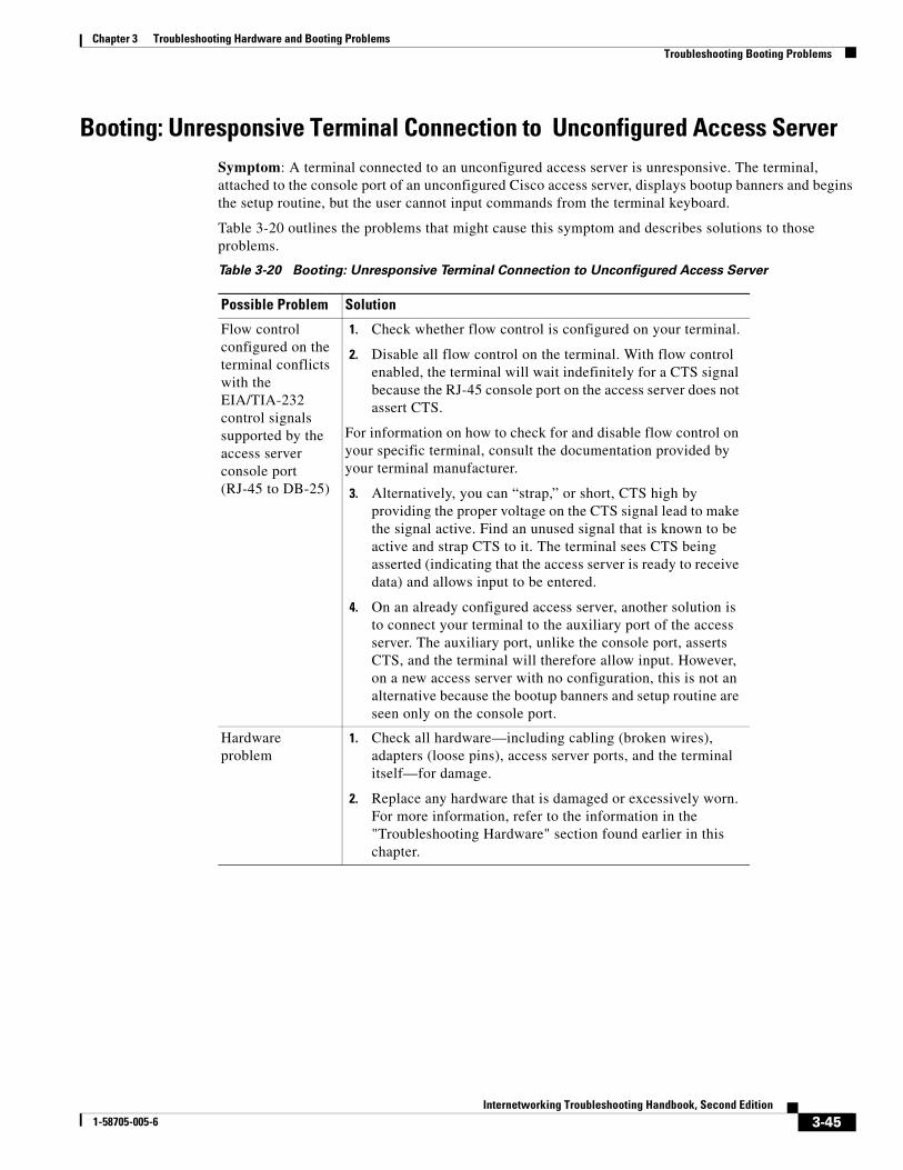
Chapter 3 Troubleshooting Hardware and Booting ProblemsTroubleshooting Booting Problems
Booting: Unresponsive Terminal Connection to Unconfigured Access ServerSymptom: A terminal connected to an unconfigured access server is unresponsive. The terminal, attached to the console port of an unconfigured Cisco access server, displays bootup banners and begins the setup routine, but the user cannot input commands from the terminal keyboard.
Table 3-20 outlines the problems that might cause this symptom and describes solutions to those problems.
Table 3-20 Booting: Unresponsive Terminal Connection to Unconfigured Access Server
Possible Problem Solution
Flow control configured on the terminal conflicts with the EIA/TIA-232 control signals supported by the access server console port (RJ-45 to DB-25)
1. Check whether flow control is configured on your terminal.
2. Disable all flow control on the terminal. With flow control enabled, the terminal will wait indefinitely for a CTS signal because the RJ-45 console port on the access server does not assert CTS.
For information on how to check for and disable flow control on your specific terminal, consult the documentation provided by your terminal manufacturer.
3. Alternatively, you can “strap,” or short, CTS high by providing the proper voltage on the CTS signal lead to make the signal active. Find an unused signal that is known to be active and strap CTS to it. The terminal sees CTS being asserted (indicating that the access server is ready to receive data) and allows input to be entered.
4. On an already configured access server, another solution is to connect your terminal to the auxiliary port of the access server. The auxiliary port, unlike the console port, asserts CTS, and the terminal will therefore allow input. However, on a new access server with no configuration, this is not an alternative because the bootup banners and setup routine are seen only on the console port.
Hardware problem
1. Check all hardware—including cabling (broken wires), adapters (loose pins), access server ports, and the terminal itself—for damage.
2. Replace any hardware that is damaged or excessively worn. For more information, refer to the information in the "Troubleshooting Hardware" section found earlier in this chapter.
3-45Internetworking Troubleshooting Handbook, Second Edition
1-58705-005-6
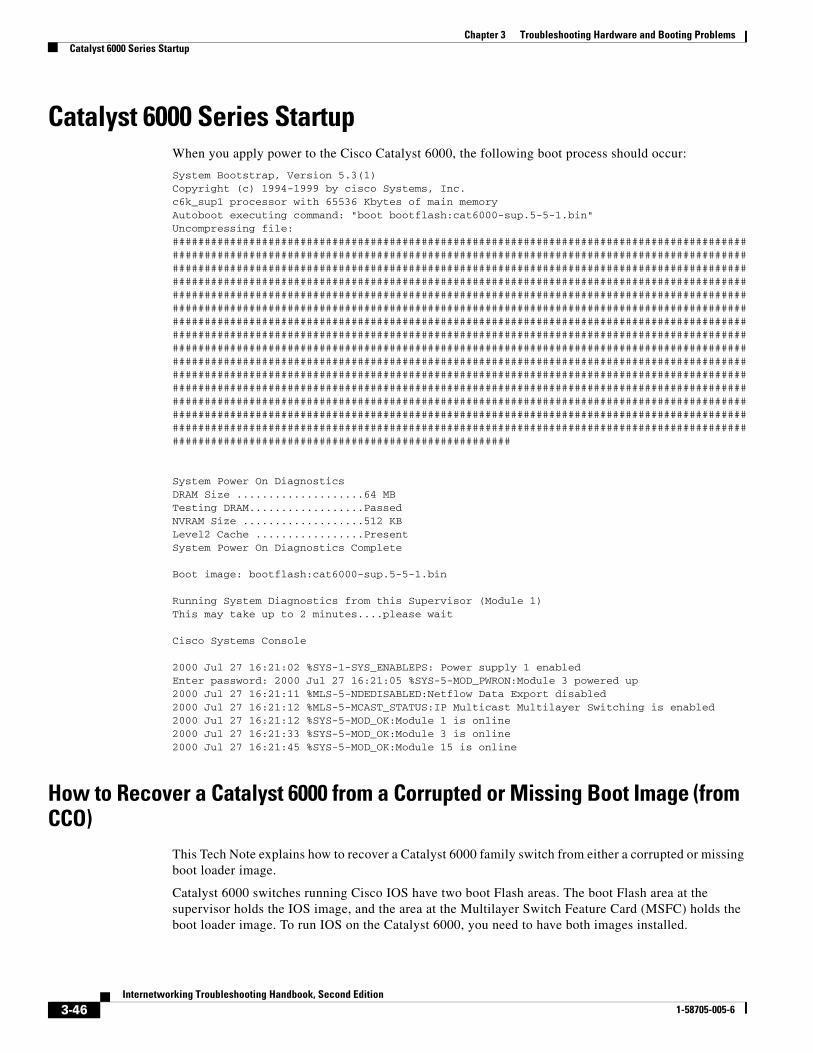
Chapter 3 Troubleshooting Hardware and Booting ProblemsCatalyst 6000 Series Startup
Catalyst 6000 Series StartupWhen you apply power to the Cisco Catalyst 6000, the following boot process should occur:
System Bootstrap, Version 5.3(1)Copyright (c) 1994-1999 by cisco Systems, Inc.c6k_sup1 processor with 65536 Kbytes of main memoryAutoboot executing command: "boot bootflash:cat6000-sup.5-5-1.bin"Uncompressing file: ###########################################################################################################################################################################################################################################################################################################################################################################################################################################################################################################################################################################################################################################################################################################################################################################################################################################################################################################################################################################################################################################################################################################################################################################################################################################################################################################################################################################################################################################################
System Power On DiagnosticsDRAM Size ....................64 MBTesting DRAM..................PassedNVRAM Size ...................512 KBLevel2 Cache .................PresentSystem Power On Diagnostics Complete
Boot image: bootflash:cat6000-sup.5-5-1.bin
Running System Diagnostics from this Supervisor (Module 1)This may take up to 2 minutes....please wait
Cisco Systems Console
2000 Jul 27 16:21:02 %SYS-1-SYS_ENABLEPS: Power supply 1 enabledEnter password: 2000 Jul 27 16:21:05 %SYS-5-MOD_PWRON:Module 3 powered up2000 Jul 27 16:21:11 %MLS-5-NDEDISABLED:Netflow Data Export disabled2000 Jul 27 16:21:12 %MLS-5-MCAST_STATUS:IP Multicast Multilayer Switching is enabled2000 Jul 27 16:21:12 %SYS-5-MOD_OK:Module 1 is online2000 Jul 27 16:21:33 %SYS-5-MOD_OK:Module 3 is online2000 Jul 27 16:21:45 %SYS-5-MOD_OK:Module 15 is online
How to Recover a Catalyst 6000 from a Corrupted or Missing Boot Image (from CCO)
This Tech Note explains how to recover a Catalyst 6000 family switch from either a corrupted or missing boot loader image.
Catalyst 6000 switches running Cisco IOS have two boot Flash areas. The boot Flash area at the supervisor holds the IOS image, and the area at the Multilayer Switch Feature Card (MSFC) holds the boot loader image. To run IOS on the Catalyst 6000, you need to have both images installed.
3-46Internetworking Troubleshooting Handbook, Second Edition
1-58705-005-6
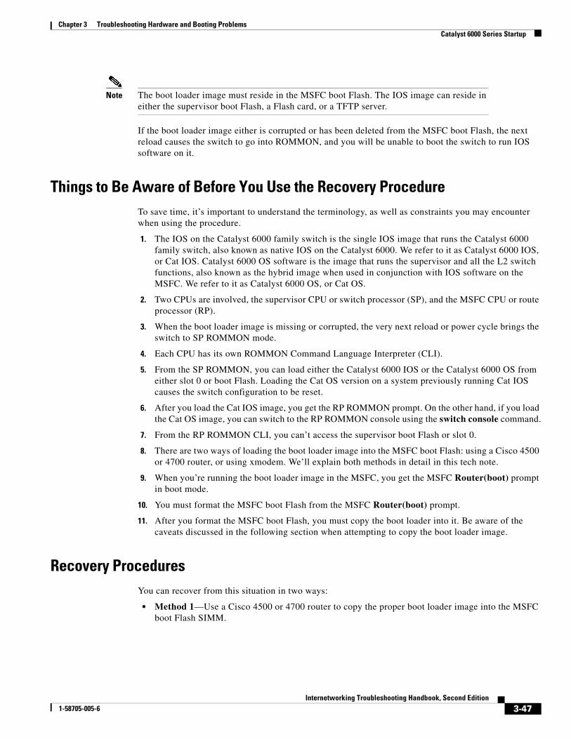
Chapter 3 Troubleshooting Hardware and Booting ProblemsCatalyst 6000 Series Startup
Note The boot loader image must reside in the MSFC boot Flash. The IOS image can reside in either the supervisor boot Flash, a Flash card, or a TFTP server.
If the boot loader image either is corrupted or has been deleted from the MSFC boot Flash, the next reload causes the switch to go into ROMMON, and you will be unable to boot the switch to run IOS software on it.
Things to Be Aware of Before You Use the Recovery ProcedureTo save time, it’s important to understand the terminology, as well as constraints you may encounter when using the procedure.
1. The IOS on the Catalyst 6000 family switch is the single IOS image that runs the Catalyst 6000 family switch, also known as native IOS on the Catalyst 6000. We refer to it as Catalyst 6000 IOS, or Cat IOS. Catalyst 6000 OS software is the image that runs the supervisor and all the L2 switch functions, also known as the hybrid image when used in conjunction with IOS software on the MSFC. We refer to it as Catalyst 6000 OS, or Cat OS.
2. Two CPUs are involved, the supervisor CPU or switch processor (SP), and the MSFC CPU or route processor (RP).
3. When the boot loader image is missing or corrupted, the very next reload or power cycle brings the switch to SP ROMMON mode.
4. Each CPU has its own ROMMON Command Language Interpreter (CLI).
5. From the SP ROMMON, you can load either the Catalyst 6000 IOS or the Catalyst 6000 OS from either slot 0 or boot Flash. Loading the Cat OS version on a system previously running Cat IOS causes the switch configuration to be reset.
6. After you load the Cat IOS image, you get the RP ROMMON prompt. On the other hand, if you load the Cat OS image, you can switch to the RP ROMMON console using the switch console command.
7. From the RP ROMMON CLI, you can’t access the supervisor boot Flash or slot 0.
8. There are two ways of loading the boot loader image into the MSFC boot Flash: using a Cisco 4500 or 4700 router, or using xmodem. We’ll explain both methods in detail in this tech note.
9. When you’re running the boot loader image in the MSFC, you get the MSFC Router(boot) prompt in boot mode.
10. You must format the MSFC boot Flash from the MSFC Router(boot) prompt.
11. After you format the MSFC boot Flash, you must copy the boot loader into it. Be aware of the caveats discussed in the following section when attempting to copy the boot loader image.
Recovery ProceduresYou can recover from this situation in two ways:
• Method 1—Use a Cisco 4500 or 4700 router to copy the proper boot loader image into the MSFC boot Flash SIMM.
3-47Internetworking Troubleshooting Handbook, Second Edition
1-58705-005-6
Chapter 3 Troubleshooting Hardware and Booting ProblemsCatalyst 6000 Series Startup
• Method 2—Use xmodem with the Modem Out-of-Band (OOB) Protocol to load the boot loader image to the MSFC boot Flash. This procedure requires the Catalyst 6000 Supervisor (CAT OS) image if using boot loader version c6msfc-boot-mz.120-7.XE, or the Catalyst IOS image if using version c6msfc-boot-mz.120-7.XE1, to be running on the Supervisor module. The MSFC boot loader image is approximately 1.8 MB and takes about 45 minutes to load.
You should use this second method only as a disaster recovery procedure, and the following caveats apply:
• The xmodem procedure doesn’t save the current switch configuration if you run the Cat OS image on the supervisor, and you were previously running Cat IOS on the switch.
• The xmodem procedure doesn’t save the downloaded image into the MSFC boot Flash.
• The xmodem procedure loads and runs the boot loader in the MFSC, and it puts it in boot mode.
– From boot mode, the MSFC boot Flash must be formatted before you copy the boot loader image into it.
– You must place the boot loader image that you want to load in supervisor’s slot 0.
Note The xmodem procedure has been verified to work with Microsoft Windows Hypertrm program, and minicom under Linux.
If these methods are not successful, contact the Cisco Technical Assistance Center (TAC), and request an RMA for a new boot Flash SIMM with the desired image in it.
Note As it was mentioned earlier, you could use either the Cat OS or Cat IOS image. Which one to use depends on the boot loader version that you are trying to load.
If you are using version c6msfc-boot-mz.120-7.XE, you need to use Cat OS image. If you use boot loader version c6msfc-boot-mz.120-7.XE1 or later, you may use the Cat IOS image. Using release c6msfc-boot-mz.120-7.XE1 or later has major advantages and should be used whenever possible. First, the switch configuration will not be lost by having to load Cat OS in the switch; second, a few extra steps are not necessary, making the process less time-consuming.
The major difference between the releases is the capability to access the supervisor’s slot 0 from boot mode. If you load Cat IOS in the supervisor, you will not be able to access slot 0 until you get to release c6msfc-boot-mz.120-7.XE1 or later.
Method 1: Boot Loader Recovery Procedure Using a Cisco 4500/4700 Router
Note The MSFC in ROMMON mode is capable of reading a 4500/4700 router Flash SIMM. However when Cat IOS is running, the MSFC cannot read a 4500/4700 flash SIMM format. Make sure that you format the MSFC boot Flash from boot mode before the boot loader image is put back on it. The following are the typical messages when attempting to read the MSFC’s boot Flash when running Cat IOS.
3-48Internetworking Troubleshooting Handbook, Second Edition
1-58705-005-6
Chapter 3 Troubleshooting Hardware and Booting ProblemsCatalyst 6000 Series Startup
MSFC in ROMMON:
rommon 1 > dir bootflash: File size Checksum File name 1597884 bytes (0x1861bc) 0x8334 c6msfc-boot-mz.120-7T.XE1.0.95.bin
MSFC in boot mode:
Router(boot)# dir bootflash: Directory of bootflash:/ 1 -rw- 1877456 Jan 01 2000 00:08:25 c6msfc-bootdbg-mz 15990784 bytes total (14113200 bytes free) Router(boot)#
MSFC running Cat IOS:
IOS4C6K# dir bootflash: %Error opening bootflash:/ (Bad device info block)
The following is the recovery procedure utilizing a 4500/4700 router.
Step 1 Remove the boot Flash from the Catalyst 6000, and put it into the 4500/4700 router. Ensure that the Flash SIMM from the slot you have selected does not contain the IOS software running the 4500/4700 router.
Important: After booting up the 4500/4700, you’ll need to partition the Flash, realizing that the boot Flash in the Catalyst 6000 is 16 M.
4500Router(config)# partition flash 2 8 16 4500Router(config)# end 4500Router# 00:07:30: %SYS-5-CONFIG_I: Configured from console by console 4500Router# show flash System flash directory, partition 1: File Length Name/status 1 4512036 c4500-js-mz.112-17.P 2 3838296 c4500-j-mz.111-20 [8350460 bytes used, 38148 available, 8388608 total] 8192K bytes of processor board System flash (Read/Write) System flash directory, partition 2: No files in System flash [0 bytes used, 16777216 available, 16777216 total] 16384K bytes of processor board System flash (Read/Write)
3-49Internetworking Troubleshooting Handbook, Second Edition
1-58705-005-6
Chapter 3 Troubleshooting Hardware and Booting ProblemsCatalyst 6000 Series Startup
Step 2 Copy the boot loader image into the appropriate system partition.
4500Router# copy tftp flash Partition Size Used Free Bank-Size State Copy Mode 1 8192K 8154K 37K 8192K Read/Write Direct 2 16384K 0K 16384K 8192K Read/Write Direct [Type ?<NO> for partition directory; ? for full directory; q to
abort] Which partition? [default = 1] 2 System flash directory, partition 2: No files in System flash [0 bytes used, 16777216 available, 16777216 total] Address or name of remote host [255.255.255.255]? tftpserver Source file name? c6msfc-boot-mz.120-7T.XE1.0.95.bin Destination file name [c6msfc-boot-mz.120-7T.XE1.0.95.bin]? Accessing file 'c6msfc-boot-mz.120-7T.XE1.0.95.bin' on
tftpserver...Loading c6msfc-boot-mz.120-7T.XE1.0.95.bin .from 172.17.196.3 (via
FastEthernet0): ! [OK] Erase flash device before writing? [confirm] Flash contains files. Are you sure you want to erase? [confirm] Copy 'c6msfc-boot-mz.120-7T.XE1.0.95.bin' from server
as 'c6msfc-boot-mz.120-7T.XE1.0.95.bin' into Flash WITH erase? [yes/no] yes
Erasing device... eeeeeeeeeeeeeeeeeeeeeeeeeeeeeeeeeeeeeeeeeeeeeeeeeeeeeeeeeeeeeeee ...erased
Loading c6msfc-boot-mz.120-7T.XE1.0.95.bin from 172.17.196.3 (via FastEthernet0 ):
!!!!!!!!!!!!!!!!!!!!!!!!!! [OK - 1599488/16777216 bytes] Verifying checksum... OK (0x13AF) Flash copy took 00:00:08 [hh:mm:ss]
Step 3 When you finish copying the image, take the SIMM back to the same slot in the Catalyst 6000.
Before the system failing, the bootvar in the Catalyst 6000 may have had the following information:
C6000-IOS# sh bootvar BOOT variable = sup-bootflash:c6sup-jsdbg-mz.120-6.5T.XE1.0.90.bin,1; CONFIG_FILE variable does not exist BOOTLDR variable = bootflash:c6msfc-boot-mz.120-6.5T.XE1.0.90.bin Configuration register is 0x2
If you did not have the bootldr variable set. you will get the following message and will have to bring up the switch manually:
System Bootstrap, Version 5.2(1)CSX Copyright (c) 1994-1999 by cisco Systems, Inc. c6k_sup1 processor with 65536 Kbytes of main memory Autoboot: failed, BOOT string is empty rommon 1 >
3-50Internetworking Troubleshooting Handbook, Second Edition
1-58705-005-6
Chapter 3 Troubleshooting Hardware and Booting ProblemsCatalyst 6000 Series Startup
To bring up the switch manually, you should have either the Cat OS or the Cat IOS image in the supervisor’s boot Flash or slot 0. To list the content of slot 0 or bootflash, type dir slot0: and dir bootflash:, respectively. See the following output.
System Bootstrap, Version 5.2(1)CSX Copyright (c) 1994-1999 by cisco Systems, Inc. c6k_sup1 processor with 65536 Kbytes of main memory rommon 1 > dir slot0: File size Checksum File name 1603124 bytes (0x187634) 0x37e92ad5 c6msfc-boot-mz.120-7T.XE1.2.02.bin
10827684 bytes (0xa537a4) 0xcdcb1ae c6sup-jsdbg-mz.120-7T.XE1.2.02.bin ** Cat IOS image **
6174451 bytes (0x5e36f3) 0xb718ee34 cat6000-sup.5-4-0-97.bin ** Cat IOS image **1877456 bytes (0x1ca5d0) 0x325c9851 c6msfc-bootdbg-mz ** MSFC boot loader image
** 8235 bytes (0x202b) 0x2a825c18 switch.cfg rommon 2 > dir bootflash: File size Checksum File name
10827684 bytes (0xa537a4) 0xcdcb1ae c6sup-jsdbg-mz.120-7T.XE1.2.02.bin *** Cat IOS image **
1603124 bytes (0x187634) 0x37e92ad5 c6msfc-boot-mz.120-7T.XE1.2.02.bin
When you have identified where the image is located, follow the instructions in one ofthese two sections:
• If you are using boot loader release c6msfc-boot-mz.120-7.XE1 or later, go to the section “Loading the Catalyst IOS Image.”
• If you are using boot loader release c6msfc-boot-mz.120-7.XE, go to the section “Loading the Catalyst OS Image.”
Come back to this point after you have loaded either the Cat IOS or the Cat OS image.
The RP is at the boot prompt, and you are ready to bring up the switch running Cat IOS. Ensure that you have the config-register set to 0x2 before you reboot. You also may want to check that the right boot variables are set correctly. If they are not, change them to reflect the right image names. See the following example:
boot system flash sup-bootflash:c6sup-jsdbg-mz.120-7T.XE1.2.02.bin boot bootldr bootflash:c6msfc-bootdbg-mz
3-51Internetworking Troubleshooting Handbook, Second Edition
1-58705-005-6
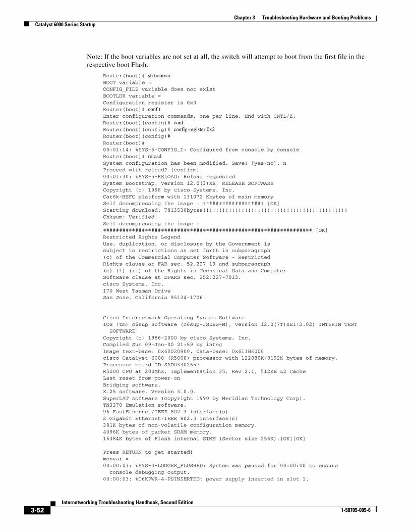
Chapter 3 Troubleshooting Hardware and Booting ProblemsCatalyst 6000 Series Startup
Note: If the boot variables are not set at all, the switch will attempt to boot from the first file in the respective boot Flash.
Router(boot)# sh bootvar BOOT variable = CONFIG_FILE variable does not exist BOOTLDR variable = Configuration register is 0x0 Router(boot)# conf t Enter configuration commands, one per line. End with CNTL/Z. Router(boot)(config)# conf Router(boot)(config)# config-register 0x2 Router(boot)(config)# Router(boot)# 00:01:14: %SYS-5-CONFIG_I: Configured from console by console Router(boot)# reload System configuration has been modified. Save? [yes/no]: n Proceed with reload? [confirm] 00:01:30: %SYS-5-RELOAD: Reload requested System Bootstrap, Version 12.0(3)XE, RELEASE SOFTWARE Copyright (c) 1998 by cisco Systems, Inc. Cat6k-MSFC platform with 131072 Kbytes of main memory Self decompressing the image : ################### [OK] Starting download: 7813530bytes!!!!!!!!!!!!!!!!!!!!!!!!!!!!!!!!!!!!!!!!!!!!! Chksum: Verified! Self decompressing the image : ################################################################# [OK] Restricted Rights Legend Use, duplication, or disclosure by the Government is subject to restrictions as set forth in subparagraph (c) of the Commercial Computer Software - Restricted Rights clause at FAR sec. 52.227-19 and subparagraph (c) (1) (ii) of the Rights in Technical Data and Computer Software clause at DFARS sec. 252.227-7013. cisco Systems, Inc. 170 West Tasman Drive San Jose, California 95134-1706
Cisco Internetwork Operating System SoftwareIOS (tm) c6sup Software (c6sup-JSDBG-M), Version 12.0(7T)XE1(2.02) INTERIM TEST
SOFTWARE Copyright (c) 1986-2000 by cisco Systems, Inc. Compiled Sun 09-Jan-00 21:59 by integ Image text-base: 0x60020900, data-base: 0x611BE000 cisco Catalyst 6000 (R5000) processor with 122880K/8192K bytes of memory. Processor board ID SAD03302657 R5000 CPU at 200Mhz, Implementation 35, Rev 2.1, 512KB L2 Cache Last reset from power-on Bridging software. X.25 software, Version 3.0.0. SuperLAT software (copyright 1990 by Meridian Technology Corp). TN3270 Emulation software. 96 FastEthernet/IEEE 802.3 interface(s) 2 Gigabit Ethernet/IEEE 802.3 interface(s) 381K bytes of non-volatile configuration memory. 4096K bytes of packet SRAM memory. 16384K bytes of Flash internal SIMM (Sector size 256K).[OK][OK]
Press RETURN to get started! monvar =
00:00:03: %SYS-3-LOGGER_FLUSHED: System was paused for 00:00:00 to ensure console debugging output.
00:00:03: %C6KPWR-4-PSINSERTED: power supply inserted in slot 1.
3-52Internetworking Troubleshooting Handbook, Second Edition
1-58705-005-6
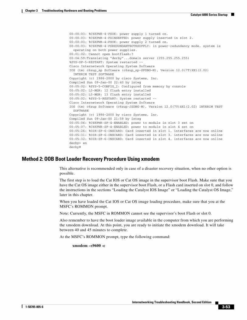
Chapter 3 Troubleshooting Hardware and Booting ProblemsCatalyst 6000 Series Startup
00:00:03: %C6KPWR-4-PSOK: power supply 1 turned on. 00:00:03: %C6KPWR-4-PSINSERTED: power supply inserted in slot 2. 00:00:03: %C6KPWR-4-PSOK: power supply 2 turned on.
00:00:03: %C6KPWR-4-PSREDUNDANTBOTHSUPPLY: in power-redundancy mode, system is operating on both power supplies.
00:01:02: Cannot open bootflash:? 00:04:59:Translating "derby"...domain server (255.255.255.255) %SYS-SP-5-RESTART: System restarted -- Cisco Internetwork Operating System Software
IOS (tm) c6sup_sp Software (c6sup_sp-SPDBG-M), Version 12.0(7T)XE1(2.02) INTERIM TEST SOFTWARE
Copyright (c) 1986-2000 by cisco Systems, Inc. Compiled Sun 09-Jan-00 22:40 by integ 00:05:02: %SYS-5-CONFIG_I: Configured from memory by console 00:05:02: L3-MGR: l2 flush entry installed 00:05:02: L3-MGR: l3 flush entry installed 00:05:02: %SYS-5-RESTART: System restarted -- Cisco Internetwork Operating System Software
IOS (tm) c6sup Software (c6sup-JSDBG-M), Version 12.0(7T)XE1(2.02) INTERIM TEST SOFTWARE
Copyright (c) 1986-2000 by cisco Systems, Inc. Compiled Sun 09-Jan-00 21:59 by integ 00:05:06: %C6KPWR-SP-4-ENABLED: power to module in slot 3 set on 00:05:07: %C6KPWR-SP-4-ENABLED: power to module in slot 4 set on
00:05:26: %OIR-SP-6-INSCARD: Card inserted in slot 1, interfaces are now online00:05:31: %OIR-SP-6-INSCARD: Card inserted in slot 3, interfaces are now online00:05:32: %OIR-SP-6-INSCARD: Card inserted in slot 4, interfaces are now onlinederby> enderby#
Method 2: OOB Boot Loader Recovery Procedure Using xmodem
This alternative is recommended only in case of a disaster recovery situation, when no other option is possible.
The first step is to load the Cat IOS or Cat OS image in the supervisor boot Flash. Make sure that you have the Cat OS image either in the supervisor boot Flash, or a Flash card inserted on slot 0, and follow the instructions in the sections “Loading the Catalyst IOS Image” or “Loading the Catalyst OS Image,” later in this chapter.
When you have loaded the Cat IOS or Cat OS image loading procedure, make sure that you at the MSFC’s ROMMON prompt.
Note: Currently, the MSFC in ROMMON cannot see the supervisor’s boot Flash or slot 0.
Also remember to have the boot loader image available in the computer from which you are performing the xmodem download. At this point, you are ready to initiate the xmodem download. It will take between 40 and 45 minutes to complete.
At the MSFC’s ROMMON prompt, type the following command:
xmodem –s9600 -c
3-53Internetworking Troubleshooting Handbook, Second Edition
1-58705-005-6
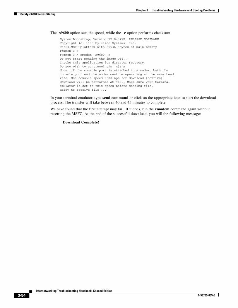
Chapter 3 Troubleshooting Hardware and Booting ProblemsCatalyst 6000 Series Startup
The -s9600 option sets the speed, while the –c option performs checksum.
System Bootstrap, Version 12.0(3)XE, RELEASE SOFTWARE Copyright (c) 1998 by cisco Systems, Inc. Cat6k-MSFC platform with 65536 Kbytes of main memory rommon 1 > rommon 1 > xmodem -s9600 -c Do not start sending the image yet... Invoke this application for disaster recovery. Do you wish to continue? y/n [n]: y Note, if the console port is attached to a modem, both the console port and the modem must be operating at the same baud rate. Use console speed 9600 bps for download [confirm] Download will be performed at 9600. Make sure your terminal emulator is set to this speed before sending file. Ready to receive file ...
In your terminal emulator, type send command or click on the appropriate icon to start the download process. The transfer will take between 40 and 45 minutes to complete.
We have found that the first attempt may fail. If it does, run the xmodem command again without resetting the MSFC. At the end of the successful download, you will the following message:
Download Complete!
3-54Internetworking Troubleshooting Handbook, Second Edition
1-58705-005-6
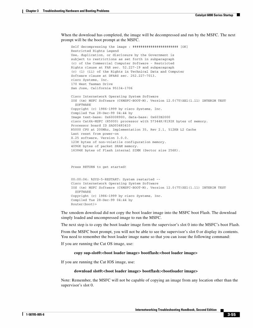
Chapter 3 Troubleshooting Hardware and Booting ProblemsCatalyst 6000 Series Startup
When the download has completed, the image will be decompressed and run by the MSFC. The next prompt will be the boot prompt at the MSFC.
Self decompressing the image : ####################### [OK] Restricted Rights Legend Use, duplication, or disclosure by the Government is subject to restrictions as set forth in subparagraph (c) of the Commercial Computer Software - Restricted Rights clause at FAR sec. 52.227-19 and subparagraph (c) (1) (ii) of the Rights in Technical Data and Computer Software clause at DFARS sec. 252.227-7013. cisco Systems, Inc. 170 West Tasman Drive San Jose, California 95134-1706 Cisco Internetwork Operating System Software
IOS (tm) MSFC Software (C6MSFC-BOOT-M), Version 12.0(7T)XE1(1.11) INTERIM TEST SOFTWARE
Copyright (c) 1986-1999 by cisco Systems, Inc. Compiled Tue 28-Dec-99 04:44 by Image text-base: 0x60008900, data-base: 0x603B2000 cisco Cat6k-MSFC (R5000) processor with 57344K/8192K bytes of memory. Processor board ID SAD03483410 R5000 CPU at 200Mhz, Implementation 35, Rev 2.1, 512KB L2 Cache Last reset from power-on X.25 software, Version 3.0.0. 123K bytes of non-volatile configuration memory. 4096K bytes of packet SRAM memory. 16384K bytes of Flash internal SIMM (Sector size 256K).
Press RETURN to get started! 00:00:04: %SYS-5-RESTART: System restarted -- Cisco Internetwork Operating System Software
IOS (tm) MSFC Software (C6MSFC-BOOT-M), Version 12.0(7T)XE1(1.11) INTERIM TEST SOFTWARE
Copyright (c) 1986-1999 by cisco Systems, Inc. Compiled Tue 28-Dec-99 04:44 by Router(boot)>
The xmodem download did not copy the boot loader image into the MSFC boot Flash. The download simply loaded and uncompressed image to run the MSFC.
The next step is to copy the boot loader image form the supervisor’s slot 0 into the MSFC’s boot Flash.
From the MSFC boot prompt, you will not be able to see the supervisor’s slot 0 or display its contents. You need to remember the boot loader image name so that you can issue the following command:
If you are running the Cat OS image, use:
copy sup-slot0:<boot loader image> bootflash:<boot loader image>
If you are running the Cat IOS image, use:
download slot0:<boot loader image> bootflash:<bootloader image>
Note: Remember, the MSFC will not be capable of copying an image from any location other than the supervisor’s slot 0.
3-55Internetworking Troubleshooting Handbook, Second Edition
1-58705-005-6
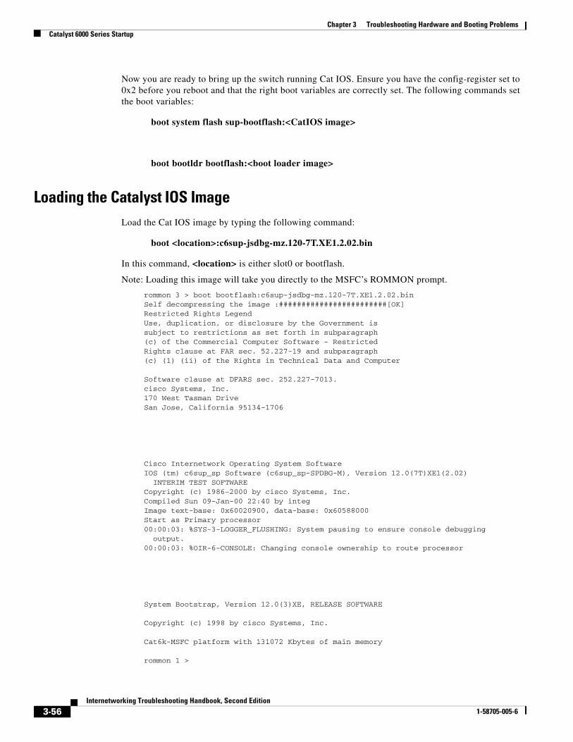
Chapter 3 Troubleshooting Hardware and Booting ProblemsCatalyst 6000 Series Startup
Now you are ready to bring up the switch running Cat IOS. Ensure you have the config-register set to 0x2 before you reboot and that the right boot variables are correctly set. The following commands set the boot variables:
boot system flash sup-bootflash:<CatIOS image>
boot bootldr bootflash:<boot loader image>
Loading the Catalyst IOS ImageLoad the Cat IOS image by typing the following command:
boot <location>:c6sup-jsdbg-mz.120-7T.XE1.2.02.bin
In this command, <location> is either slot0 or bootflash.
Note: Loading this image will take you directly to the MSFC’s ROMMON prompt.
rommon 3 > boot bootflash:c6sup-jsdbg-mz.120-7T.XE1.2.02.bin Self decompressing the image :########################[OK] Restricted Rights Legend Use, duplication, or disclosure by the Government is subject to restrictions as set forth in subparagraph (c) of the Commercial Computer Software - Restricted Rights clause at FAR sec. 52.227-19 and subparagraph (c) (1) (ii) of the Rights in Technical Data and Computer
Software clause at DFARS sec. 252.227-7013. cisco Systems, Inc. 170 West Tasman Drive San Jose, California 95134-1706
Cisco Internetwork Operating System SoftwareIOS (tm) c6sup_sp Software (c6sup_sp-SPDBG-M), Version 12.0(7T)XE1(2.02)
INTERIM TEST SOFTWARE Copyright (c) 1986-2000 by cisco Systems, Inc. Compiled Sun 09-Jan-00 22:40 by integ Image text-base: 0x60020900, data-base: 0x60588000 Start as Primary processor 00:00:03: %SYS-3-LOGGER_FLUSHING: System pausing to ensure console debugging
output. 00:00:03: %OIR-6-CONSOLE: Changing console ownership to route processor
System Bootstrap, Version 12.0(3)XE, RELEASE SOFTWARE
Copyright (c) 1998 by cisco Systems, Inc.
Cat6k-MSFC platform with 131072 Kbytes of main memory
rommon 1 >
3-56Internetworking Troubleshooting Handbook, Second Edition
1-58705-005-6

Chapter 3 Troubleshooting Hardware and Booting ProblemsCatalyst 6000 Series Startup
At this point, the MSFC must run the boot loader image. Display the contents of the MSFC’s boot Flash to ensure that the boot loader image is there. Type the following command:
rommon 2 > dir bootflash:
File size Checksum File name
1877456 bytes (0x1ca5d0) 0x325c9851 c6msfc-bootdbg-mz
Now boot the MSFC using the boot loader image, as follows:
rommon 3 > boot bootflash:c6msfc-bootdbg-mz
Self decompressing the image : ################ [OK] Restricted Rights Legend Use, duplication, or disclosure by the Government is subject to restrictions as set forth in subparagraph (c) of the Commercial Computer Software - Restricted Rights clause at FAR sec. 52.227-19 and subparagraph (c) (1) (ii) of the Rights in Technical Data and Computer Software clause at DFARS sec. 252.227-7013. cisco Systems, Inc. 170 West Tasman Drive San Jose, California 95134-1706 Cisco Internetwork Operating System Software
IOS (tm) MSFC Software (C6MSFC-BOOTDBG-M), Experimental Version 12.1(20000118:211435) [slarson-cosmos_e2 321]
Copyright (c) 1986-2000 by cisco Systems, Inc. Compiled Wed 19-Jan-00 16:23 by slarson Image text-base: 0x60008900, data-base: 0x603C4000 cisco Cat6k-MSFC (R5000) processor with 122880K/8192K bytes of memory. Processor board ID SAD03302657 R5000 CPU at 200Mhz, Implementation 35, Rev 2.1, 512KB L2 Cache Last reset from power-on X.25 software, Version 3.0.0. 123K bytes of non-volatile configuration memory.
4096K bytes of packet SRAM memory. 16384K bytes of Flash internal SIMM (Sector size 256K).
Press RETURN to get started! 00:00:04: %SYS-5-RESTART: System restarted -- Cisco Internetwork Operating System Software IOS (tm) MSFC Software (C6MSFC-BOOTDBG-M), Experimental Version
12.1(20000118:211435) [slarson-cosmos_e2 321] Copyright (c) 1986-2000 by cisco Systems, Inc. Compiled Wed 19-Jan-00 16:23 by slarson Router(boot)> en Router(boot)#
You now need to format the MSFC’s boot Flash and copy the boot loader image from the supervisor’s slot 0.
3-57Internetworking Troubleshooting Handbook, Second Edition
1-58705-005-6
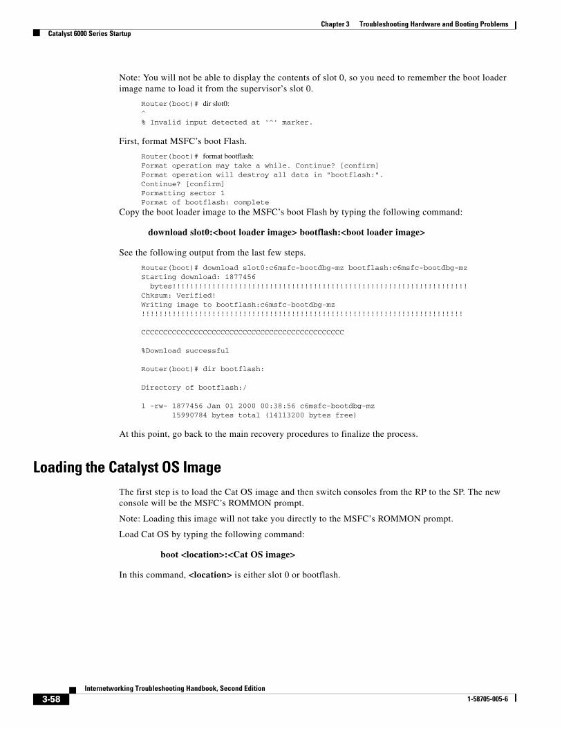
Chapter 3 Troubleshooting Hardware and Booting ProblemsCatalyst 6000 Series Startup
Note: You will not be able to display the contents of slot 0, so you need to remember the boot loader image name to load it from the supervisor’s slot 0.
Router(boot)# dir slot0: ^ % Invalid input detected at '^' marker.
First, format MSFC’s boot Flash.
Router(boot)# format bootflash: Format operation may take a while. Continue? [confirm] Format operation will destroy all data in "bootflash:". Continue? [confirm] Formatting sector 1 Format of bootflash: complete
Copy the boot loader image to the MSFC’s boot Flash by typing the following command:
download slot0:<boot loader image> bootflash:<boot loader image>
See the following output from the last few steps.
Router(boot)# download slot0:c6msfc-bootdbg-mz bootflash:c6msfc-bootdbg-mz Starting download: 1877456
bytes!!!!!!!!!!!!!!!!!!!!!!!!!!!!!!!!!!!!!!!!!!!!!!!!!!!!!!!!!!!!!!!!!!! Chksum: Verified! Writing image to bootflash:c6msfc-bootdbg-mz !!!!!!!!!!!!!!!!!!!!!!!!!!!!!!!!!!!!!!!!!!!!!!!!!!!!!!!!!!!!!!!!!!!!!!!!!
CCCCCCCCCCCCCCCCCCCCCCCCCCCCCCCCCCCCCCCCCCCCCC
%Download successful
Router(boot)# dir bootflash:
Directory of bootflash:/
1 -rw- 1877456 Jan 01 2000 00:38:56 c6msfc-bootdbg-mz 15990784 bytes total (14113200 bytes free)
At this point, go back to the main recovery procedures to finalize the process.
Loading the Catalyst OS ImageThe first step is to load the Cat OS image and then switch consoles from the RP to the SP. The new console will be the MSFC’s ROMMON prompt.
Note: Loading this image will not take you directly to the MSFC’s ROMMON prompt.
Load Cat OS by typing the following command:
boot <location>:<Cat OS image>
In this command, <location> is either slot 0 or bootflash.
3-58Internetworking Troubleshooting Handbook, Second Edition
1-58705-005-6
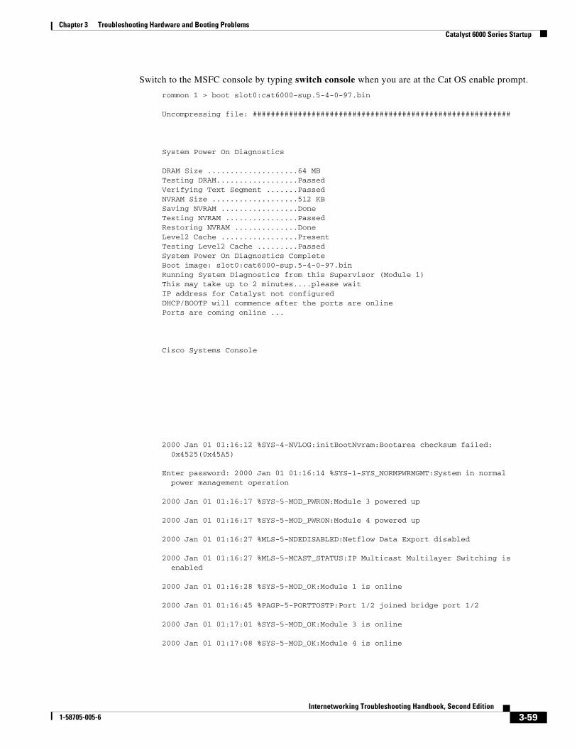
Chapter 3 Troubleshooting Hardware and Booting ProblemsCatalyst 6000 Series Startup
Switch to the MSFC console by typing switch console when you are at the Cat OS enable prompt.
rommon 1 > boot slot0:cat6000-sup.5-4-0-97.bin
Uncompressing file: #########################################################
System Power On Diagnostics
DRAM Size ....................64 MB Testing DRAM..................Passed Verifying Text Segment .......Passed NVRAM Size ...................512 KB Saving NVRAM .................Done Testing NVRAM ................Passed Restoring NVRAM ..............Done Level2 Cache .................Present Testing Level2 Cache .........Passed System Power On Diagnostics Complete Boot image: slot0:cat6000-sup.5-4-0-97.bin Running System Diagnostics from this Supervisor (Module 1) This may take up to 2 minutes....please wait IP address for Catalyst not configured DHCP/BOOTP will commence after the ports are online Ports are coming online ...
Cisco Systems Console
2000 Jan 01 01:16:12 %SYS-4-NVLOG:initBootNvram:Bootarea checksum failed: 0x4525(0x45A5)
Enter password: 2000 Jan 01 01:16:14 %SYS-1-SYS_NORMPWRMGMT:System in normal power management operation
2000 Jan 01 01:16:17 %SYS-5-MOD_PWRON:Module 3 powered up
2000 Jan 01 01:16:17 %SYS-5-MOD_PWRON:Module 4 powered up
2000 Jan 01 01:16:27 %MLS-5-NDEDISABLED:Netflow Data Export disabled
2000 Jan 01 01:16:27 %MLS-5-MCAST_STATUS:IP Multicast Multilayer Switching is enabled
2000 Jan 01 01:16:28 %SYS-5-MOD_OK:Module 1 is online
2000 Jan 01 01:16:45 %PAGP-5-PORTTOSTP:Port 1/2 joined bridge port 1/2
2000 Jan 01 01:17:01 %SYS-5-MOD_OK:Module 3 is online
2000 Jan 01 01:17:08 %SYS-5-MOD_OK:Module 4 is online
3-59Internetworking Troubleshooting Handbook, Second Edition
1-58705-005-6
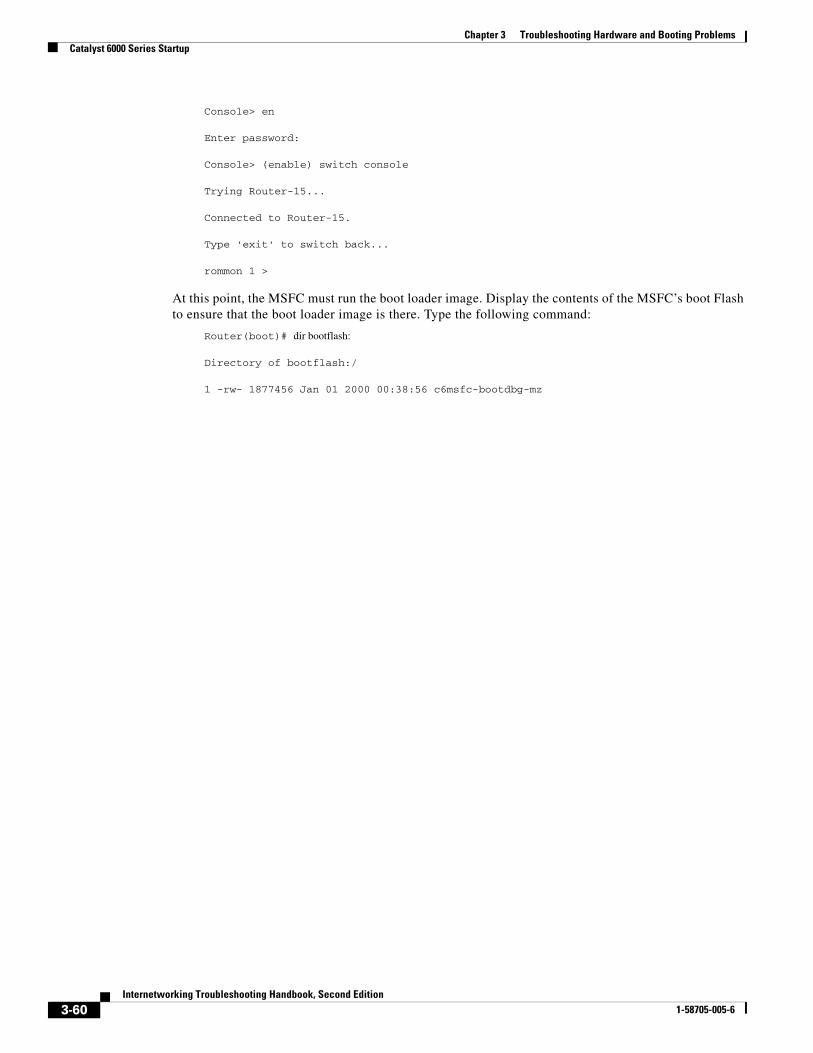
Chapter 3 Troubleshooting Hardware and Booting ProblemsCatalyst 6000 Series Startup
Console> en
Enter password:
Console> (enable) switch console
Trying Router-15...
Connected to Router-15.
Type 'exit' to switch back...
rommon 1 >
At this point, the MSFC must run the boot loader image. Display the contents of the MSFC’s boot Flash to ensure that the boot loader image is there. Type the following command:
Router(boot)# dir bootflash:
Directory of bootflash:/
1 -rw- 1877456 Jan 01 2000 00:38:56 c6msfc-bootdbg-mz
3-60Internetworking Troubleshooting Handbook, Second Edition
1-58705-005-6

Chapter 3 Troubleshooting Hardware and Booting ProblemsCatalyst 6000 Series Startup
Now boot the MSFC using the boot loader image, as follows:
rommon 5 > boot bootflash:c6msfc-bootdbg-mz
Self decompressing the image : ################## [OK]
Restricted Rights Legend
Use, duplication, or disclosure by the Government is
subject to restrictions as set forth in subparagraph
(c) of the Commercial Computer Software - Restricted
Rights clause at FAR sec. 52.227-19 and subparagraph
(c) (1) (ii) of the Rights in Technical Data and Computer
Software clause at DFARS sec. 252.227-7013.
cisco Systems, Inc.
170 West Tasman Drive
San Jose, California 95134-1706
Cisco Internetwork Operating System Software
IOS (tm) MSFC Software (C6MSFC-BOOTDBG-M), Experimental Version 12.1(20000118:211435) [slarson-cosmos_e2 321]
Copyright (c) 1986-2000 by cisco Systems, Inc.
Compiled Wed 19-Jan-00 16:23 by slarson
Image text-base: 0x60008900, data-base: 0x603C4000
cisco Cat6k-MSFC (R5000) processor with 122880K/8192K bytes of memory.
Processor board ID SAD03302657
R5000 CPU at 200Mhz, Implementation 35, Rev 2.1, 512KB L2 Cache
Last reset from power-on
X.25 software, Version 3.0.0.
123K bytes of non-volatile configuration memory.
4096K bytes of packet SRAM memory.
16384K bytes of Flash internal SIMM (Sector size 256K).
Press RETURN to get started!
Module online.
3-61Internetworking Troubleshooting Handbook, Second Edition
1-58705-005-6
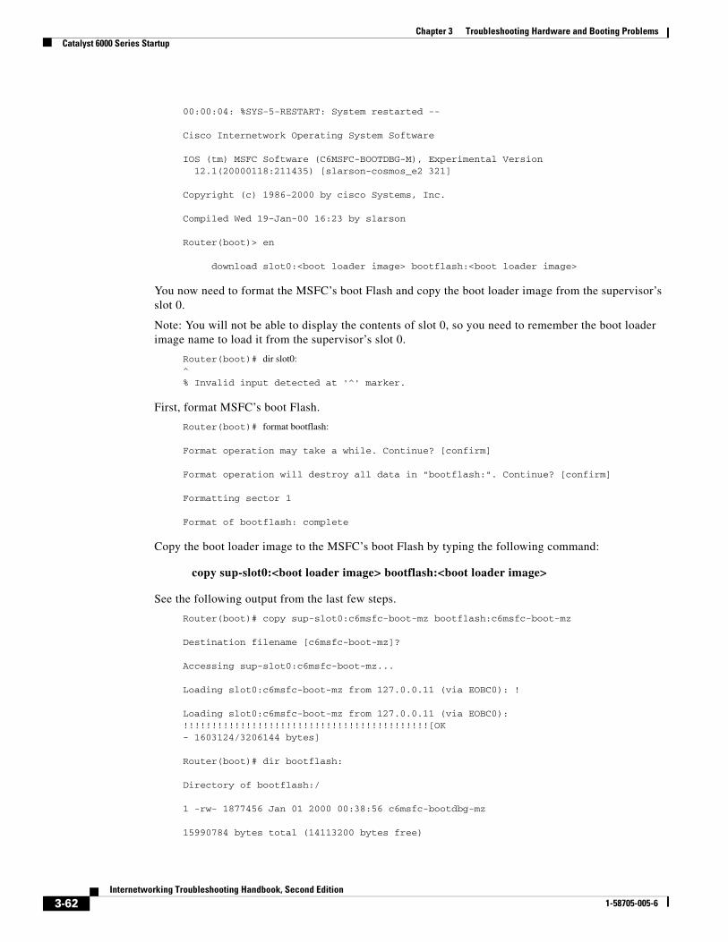
Chapter 3 Troubleshooting Hardware and Booting ProblemsCatalyst 6000 Series Startup
00:00:04: %SYS-5-RESTART: System restarted --
Cisco Internetwork Operating System Software
IOS (tm) MSFC Software (C6MSFC-BOOTDBG-M), Experimental Version 12.1(20000118:211435) [slarson-cosmos_e2 321]
Copyright (c) 1986-2000 by cisco Systems, Inc.
Compiled Wed 19-Jan-00 16:23 by slarson
Router(boot)> en
download slot0:<boot loader image> bootflash:<boot loader image>
You now need to format the MSFC’s boot Flash and copy the boot loader image from the supervisor’s slot 0.
Note: You will not be able to display the contents of slot 0, so you need to remember the boot loader image name to load it from the supervisor’s slot 0.
Router(boot)# dir slot0: ^ % Invalid input detected at '^' marker.
First, format MSFC’s boot Flash.
Router(boot)# format bootflash:
Format operation may take a while. Continue? [confirm]
Format operation will destroy all data in "bootflash:". Continue? [confirm]
Formatting sector 1
Format of bootflash: complete
Copy the boot loader image to the MSFC’s boot Flash by typing the following command:
copy sup-slot0:<boot loader image> bootflash:<boot loader image>
See the following output from the last few steps.
Router(boot)# copy sup-slot0:c6msfc-boot-mz bootflash:c6msfc-boot-mz
Destination filename [c6msfc-boot-mz]?
Accessing sup-slot0:c6msfc-boot-mz...
Loading slot0:c6msfc-boot-mz from 127.0.0.11 (via EOBC0): !
Loading slot0:c6msfc-boot-mz from 127.0.0.11 (via EOBC0): !!!!!!!!!!!!!!!!!!!!!!!!!!!!!!!!!!!!!!!!!!![OK - 1603124/3206144 bytes]
Router(boot)# dir bootflash:
Directory of bootflash:/
1 -rw- 1877456 Jan 01 2000 00:38:56 c6msfc-bootdbg-mz
15990784 bytes total (14113200 bytes free)
3-62Internetworking Troubleshooting Handbook, Second Edition
1-58705-005-6
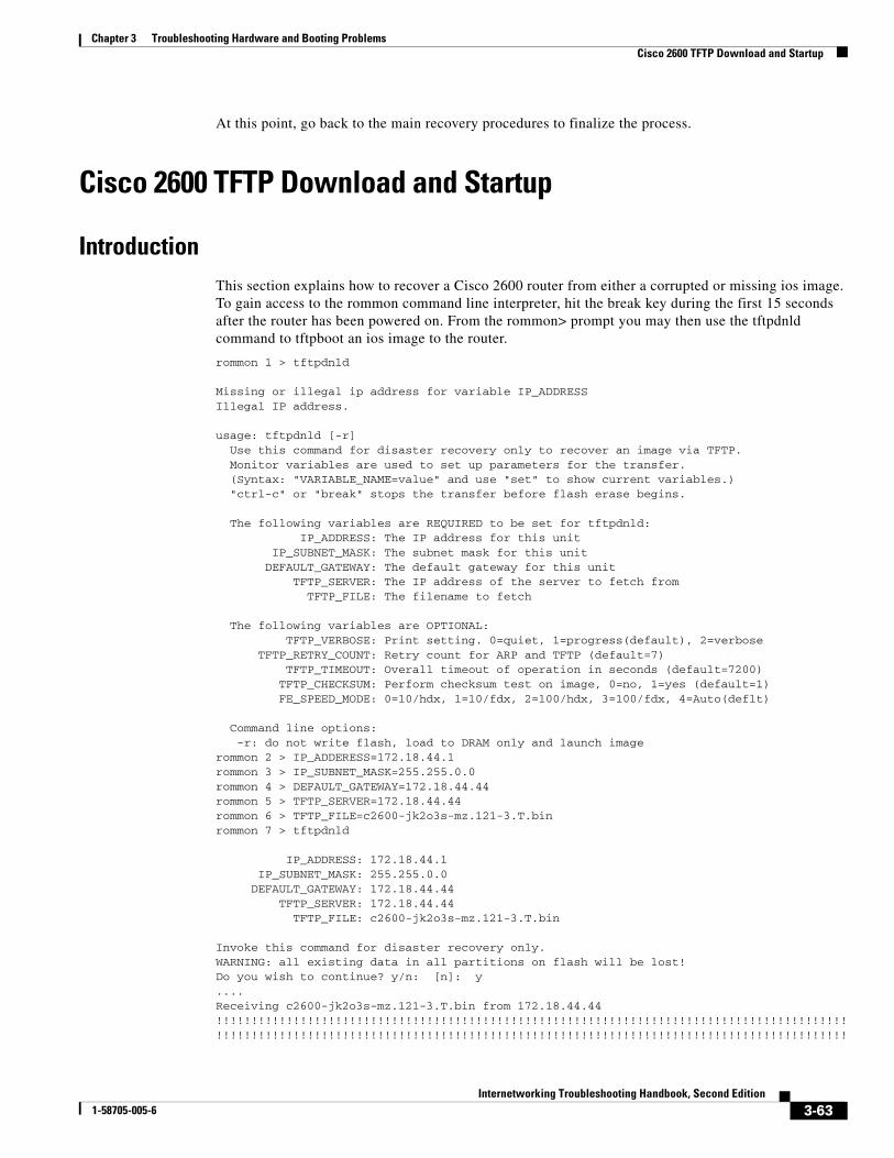
Chapter 3 Troubleshooting Hardware and Booting ProblemsCisco 2600 TFTP Download and Startup
At this point, go back to the main recovery procedures to finalize the process.
Cisco 2600 TFTP Download and Startup
IntroductionThis section explains how to recover a Cisco 2600 router from either a corrupted or missing ios image. To gain access to the rommon command line interpreter, hit the break key during the first 15 seconds after the router has been powered on. From the rommon> prompt you may then use the tftpdnld command to tftpboot an ios image to the router.
rommon 1 > tftpdnld
Missing or illegal ip address for variable IP_ADDRESSIllegal IP address.
usage: tftpdnld [-r] Use this command for disaster recovery only to recover an image via TFTP. Monitor variables are used to set up parameters for the transfer. (Syntax: "VARIABLE_NAME=value" and use "set" to show current variables.) "ctrl-c" or "break" stops the transfer before flash erase begins.
The following variables are REQUIRED to be set for tftpdnld: IP_ADDRESS: The IP address for this unit IP_SUBNET_MASK: The subnet mask for this unit DEFAULT_GATEWAY: The default gateway for this unit TFTP_SERVER: The IP address of the server to fetch from TFTP_FILE: The filename to fetch
The following variables are OPTIONAL: TFTP_VERBOSE: Print setting. 0=quiet, 1=progress(default), 2=verbose TFTP_RETRY_COUNT: Retry count for ARP and TFTP (default=7) TFTP_TIMEOUT: Overall timeout of operation in seconds (default=7200) TFTP_CHECKSUM: Perform checksum test on image, 0=no, 1=yes (default=1) FE_SPEED_MODE: 0=10/hdx, 1=10/fdx, 2=100/hdx, 3=100/fdx, 4=Auto(deflt)
Command line options: -r: do not write flash, load to DRAM only and launch imagerommon 2 > IP_ADDERESS=172.18.44.1rommon 3 > IP_SUBNET_MASK=255.255.0.0rommon 4 > DEFAULT_GATEWAY=172.18.44.44rommon 5 > TFTP_SERVER=172.18.44.44rommon 6 > TFTP_FILE=c2600-jk2o3s-mz.121-3.T.binrommon 7 > tftpdnld
IP_ADDRESS: 172.18.44.1 IP_SUBNET_MASK: 255.255.0.0 DEFAULT_GATEWAY: 172.18.44.44 TFTP_SERVER: 172.18.44.44 TFTP_FILE: c2600-jk2o3s-mz.121-3.T.bin
Invoke this command for disaster recovery only.WARNING: all existing data in all partitions on flash will be lost!Do you wish to continue? y/n: [n]: y....Receiving c2600-jk2o3s-mz.121-3.T.bin from 172.18.44.44 !!!!!!!!!!!!!!!!!!!!!!!!!!!!!!!!!!!!!!!!!!!!!!!!!!!!!!!!!!!!!!!!!!!!!!!!!!!!!!!!!!!!!!!!!!!!!!!!!!!!!!!!!!!!!!!!!!!!!!!!!!!!!!!!!!!!!!!!!!!!!!!!!!!!!!!!!!!!!!!!!!!!!!!!!!!!!!!!!!!!
3-63Internetworking Troubleshooting Handbook, Second Edition
1-58705-005-6
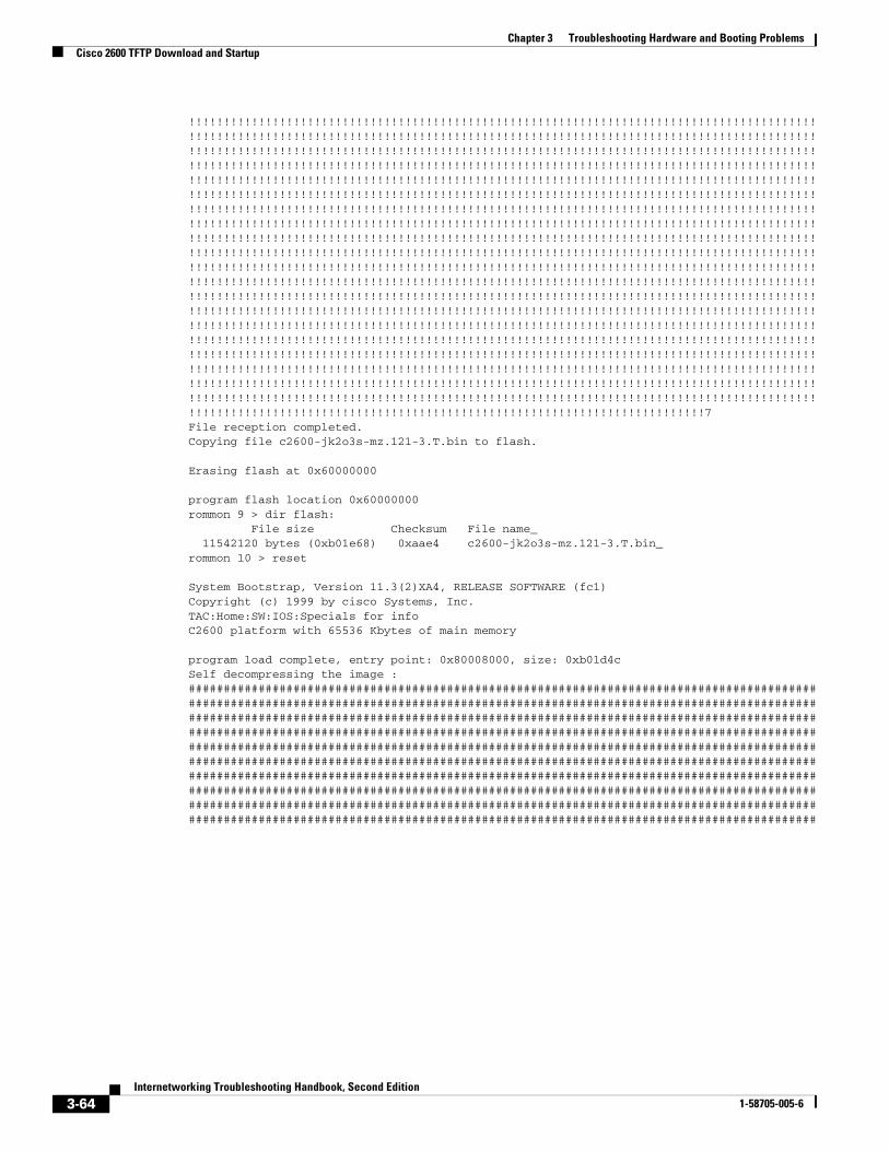
Chapter 3 Troubleshooting Hardware and Booting ProblemsCisco 2600 TFTP Download and Startup
!!!!!!!!!!!!!!!!!!!!!!!!!!!!!!!!!!!!!!!!!!!!!!!!!!!!!!!!!!!!!!!!!!!!!!!!!!!!!!!!!!!!!!!!!!!!!!!!!!!!!!!!!!!!!!!!!!!!!!!!!!!!!!!!!!!!!!!!!!!!!!!!!!!!!!!!!!!!!!!!!!!!!!!!!!!!!!!!!!!!!!!!!!!!!!!!!!!!!!!!!!!!!!!!!!!!!!!!!!!!!!!!!!!!!!!!!!!!!!!!!!!!!!!!!!!!!!!!!!!!!!!!!!!!!!!!!!!!!!!!!!!!!!!!!!!!!!!!!!!!!!!!!!!!!!!!!!!!!!!!!!!!!!!!!!!!!!!!!!!!!!!!!!!!!!!!!!!!!!!!!!!!!!!!!!!!!!!!!!!!!!!!!!!!!!!!!!!!!!!!!!!!!!!!!!!!!!!!!!!!!!!!!!!!!!!!!!!!!!!!!!!!!!!!!!!!!!!!!!!!!!!!!!!!!!!!!!!!!!!!!!!!!!!!!!!!!!!!!!!!!!!!!!!!!!!!!!!!!!!!!!!!!!!!!!!!!!!!!!!!!!!!!!!!!!!!!!!!!!!!!!!!!!!!!!!!!!!!!!!!!!!!!!!!!!!!!!!!!!!!!!!!!!!!!!!!!!!!!!!!!!!!!!!!!!!!!!!!!!!!!!!!!!!!!!!!!!!!!!!!!!!!!!!!!!!!!!!!!!!!!!!!!!!!!!!!!!!!!!!!!!!!!!!!!!!!!!!!!!!!!!!!!!!!!!!!!!!!!!!!!!!!!!!!!!!!!!!!!!!!!!!!!!!!!!!!!!!!!!!!!!!!!!!!!!!!!!!!!!!!!!!!!!!!!!!!!!!!!!!!!!!!!!!!!!!!!!!!!!!!!!!!!!!!!!!!!!!!!!!!!!!!!!!!!!!!!!!!!!!!!!!!!!!!!!!!!!!!!!!!!!!!!!!!!!!!!!!!!!!!!!!!!!!!!!!!!!!!!!!!!!!!!!!!!!!!!!!!!!!!!!!!!!!!!!!!!!!!!!!!!!!!!!!!!!!!!!!!!!!!!!!!!!!!!!!!!!!!!!!!!!!!!!!!!!!!!!!!!!!!!!!!!!!!!!!!!!!!!!!!!!!!!!!!!!!!!!!!!!!!!!!!!!!!!!!!!!!!!!!!!!!!!!!!!!!!!!!!!!!!!!!!!!!!!!!!!!!!!!!!!!!!!!!!!!!!!!!!!!!!!!!!!!!!!!!!!!!!!!!!!!!!!!!!!!!!!!!!!!!!!!!!!!!!!!!!!!!!!!!!!!!!!!!!!!!!!!!!!!!!!!!!!!!!!!!!!!!!!!!!!!!!!!!!!!!!!!!!!!!!!!!!!!!!!!!!!!!!!!!!!!!!!!!!!!!!!!!!!!!!!!!!!!!!!!!!!!!!!!!!!!!!!!!!!!!!!!!!!!!!!!!!!!!!!!!!!!!!!!!!!!!!!!!!!!!!!!!!!!!!!!!!!!!!!!!!!!!!!!!!!!!!!!!!!!!!!!!!!!!!!!!!!!!!!!!!!!!!!!!!!!!!!!!!!!!!!!!!!!!!!!!!!!!!!!!!!!!!!!!!!!!!!!!!!!!!!!!!!!!!!!!!!!!!!!!!!!!!!!!!!!!!!!!!!!!!!!!!!!!!!!!!!!!!!!!!!!!!!!!!!!!!!!!!!!!!!!!!!!!!!!!!!!!!!!!!!!!!!!!!!!!!!!!!!!!!!!!!!!!!!!!!!!!!!!!!!!!!!!!!!!!!!!!!!!!!!!!!!!!!!!!!!!!!!!!!!!!!!!!!!!!!!!!!!!!!!!!!!!!!!!!!!!!!!!!!!!!!!!!!!!!!!!!!!!!!!!!!!!!!!!!!!!!!!!!!!!!!!!!!!!!!!!!!!!!!!!!!!!!!!!!!!!!!!!!!!!!!!!!!!!!!!!!!!!!!!!!!!!!!!!!!!!!!!!!!!!!!!!!!!!!!!!!!!!!!!!7File reception completed.Copying file c2600-jk2o3s-mz.121-3.T.bin to flash.
Erasing flash at 0x60000000
program flash location 0x60000000rommon 9 > dir flash: File size Checksum File name_ 11542120 bytes (0xb01e68) 0xaae4 c2600-jk2o3s-mz.121-3.T.bin_rommon 10 > reset
System Bootstrap, Version 11.3(2)XA4, RELEASE SOFTWARE (fc1)Copyright (c) 1999 by cisco Systems, Inc.TAC:Home:SW:IOS:Specials for infoC2600 platform with 65536 Kbytes of main memory
program load complete, entry point: 0x80008000, size: 0xb01d4cSelf decompressing the image : ####################################################################################################################################################################################################################################################################################################################################################################################################################################################################################################################################################################################################################################################################################################################################################################################################################################################################################################################################
3-64Internetworking Troubleshooting Handbook, Second Edition
1-58705-005-6
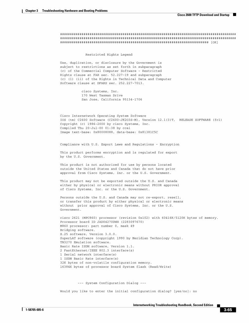
Chapter 3 Troubleshooting Hardware and Booting ProblemsCisco 2600 TFTP Download and Startup
################################################################################################################################################################################################################################################################ [OK]
Restricted Rights Legend
Use, duplication, or disclosure by the Government issubject to restrictions as set forth in subparagraph(c) of the Commercial Computer Software - RestrictedRights clause at FAR sec. 52.227-19 and subparagraph(c) (1) (ii) of the Rights in Technical Data and ComputerSoftware clause at DFARS sec. 252.227-7013.
cisco Systems, Inc. 170 West Tasman Drive San Jose, California 95134-1706
Cisco Internetwork Operating System SoftwareIOS (tm) C2600 Software (C2600-JK2O3S-M), Version 12.1(3)T, RELEASE SOFTWARE (fc1)Copyright (c) 1986-2000 by cisco Systems, Inc.Compiled Thu 20-Jul-00 01:38 by ccaiImage text-base: 0x80008088, data-base: 0x81381C5C
Compliance with U.S. Export Laws and Regulations - Encryption
This product performs encryption and is regulated for exportby the U.S. Government.
This product is not authorized for use by persons locatedoutside the United States and Canada that do not have priorapproval from Cisco Systems, Inc. or the U.S. Government.
This product may not be exported outside the U.S. and Canadaeither by physical or electronic means without PRIOR approvalof Cisco Systems, Inc. or the U.S. Government.
Persons outside the U.S. and Canada may not re-export, resell,or transfer this product by either physical or electronic meanswithout prior approval of Cisco Systems, Inc. or the U.S.Government.
cisco 2621 (MPC860) processor (revision 0x102) with 60416K/5120K bytes of memory.Processor board ID JAD04270DWH (2283097670)M860 processor: part number 0, mask 49Bridging software.X.25 software, Version 3.0.0.SuperLAT software (copyright 1990 by Meridian Technology Corp).TN3270 Emulation software.Basic Rate ISDN software, Version 1.1.2 FastEthernet/IEEE 802.3 interface(s)1 Serial network interface(s)1 ISDN Basic Rate interface(s)32K bytes of non-volatile configuration memory.16384K bytes of processor board System flash (Read/Write)
--- System Configuration Dialog ---
Would you like to enter the initial configuration dialog? [yes/no]: no
3-65Internetworking Troubleshooting Handbook, Second Edition
1-58705-005-6
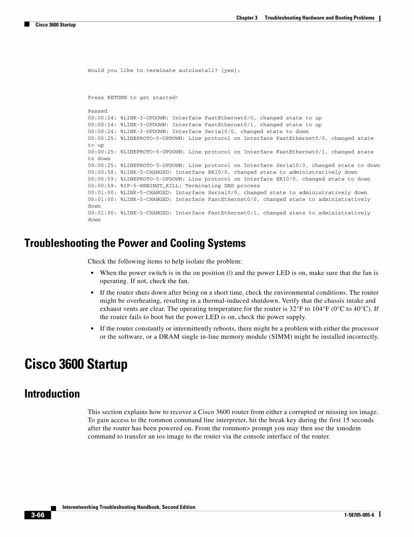
Chapter 3 Troubleshooting Hardware and Booting ProblemsCisco 3600 Startup
Would you like to terminate autoinstall? [yes]:
Press RETURN to get started!
Passed00:00:24: %LINK-3-UPDOWN: Interface FastEthernet0/0, changed state to up00:00:24: %LINK-3-UPDOWN: Interface FastEthernet0/1, changed state to up00:00:24: %LINK-3-UPDOWN: Interface Serial0/0, changed state to down00:00:25: %LINEPROTO-5-UPDOWN: Line protocol on Interface FastEthernet0/0, changed state to up00:00:25: %LINEPROTO-5-UPDOWN: Line protocol on Interface FastEthernet0/1, changed state to down00:00:25: %LINEPROTO-5-UPDOWN: Line protocol on Interface Serial0/0, changed state to down00:00:58: %LINK-5-CHANGED: Interface BRI0/0, changed state to administratively down00:00:59: %LINEPROTO-5-UPDOWN: Line protocol on Interface BRI0/0, changed state to down00:00:59: %IP-5-WEBINST_KILL: Terminating DNS process00:01:00: %LINK-5-CHANGED: Interface Serial0/0, changed state to administratively down00:01:00: %LINK-5-CHANGED: Interface FastEthernet0/0, changed state to administratively down00:01:00: %LINK-5-CHANGED: Interface FastEthernet0/1, changed state to administratively down
Troubleshooting the Power and Cooling SystemsCheck the following items to help isolate the problem:
• When the power switch is in the on position (|) and the power LED is on, make sure that the fan is operating. If not, check the fan.
• If the router shuts down after being on a short time, check the environmental conditions. The router might be overheating, resulting in a thermal-induced shutdown. Verify that the chassis intake and exhaust vents are clear. The operating temperature for the router is 32°F to 104°F (0°C to 40°C). If the router fails to boot but the power LED is on, check the power supply.
• If the router constantly or intermittently reboots, there might be a problem with either the processor or the software, or a DRAM single in-line memory module (SIMM) might be installed incorrectly.
Cisco 3600 Startup
IntroductionThis section explains how to recover a Cisco 3600 router from either a corrupted or missing ios image. To gain access to the rommon command line interpreter, hit the break key during the first 15 seconds after the router has been powered on. From the rommon> prompt you may then use the xmodem command to transfer an ios image to the router via the console interface of the router.
3-66Internetworking Troubleshooting Handbook, Second Edition
1-58705-005-6
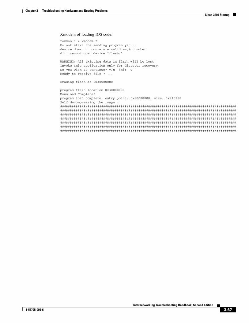
Chapter 3 Troubleshooting Hardware and Booting ProblemsCisco 3600 Startup
Xmodem of loading IOS code:
rommon 1 > xmodem ?Do not start the sending program yet...device does not contain a valid magic numberdir: cannot open device "flash:"
WARNING: All existing data in flash will be lost!Invoke this application only for disaster recovery.Do you wish to continue? y/n [n]: yReady to receive file ? ...
Erasing flash at 0x30000000
program flash location 0x30000000Download Complete!program load complete, entry point: 0x80008000, size: 0xa10988Self decompressing the image : ######################################################################################################################################################################################################################################################################################################################################################################################################################################################################################################################################################################################################################################################
3-67Internetworking Troubleshooting Handbook, Second Edition
1-58705-005-6

Chapter 3 Troubleshooting Hardware and Booting ProblemsCisco 3600 Startup
###################################################################################################################################################################################################### [OK]
Restricted Rights Legend
Use, duplication, or disclosure by the Government issubject to restrictions as set forth in subparagraph(c) of the Commercial Computer Software - RestrictedRights clause at FAR sec. 52.227-19 and subparagraph(c) (1) (ii) of the Rights in Technical Data and ComputerSoftware clause at DFARS sec. 252.227-7013.
cisco Systems, Inc. 170 West Tasman Drive San Jose, California 95134-1706
Cisco Internetwork Operating System SoftwareIOS (tm) 3600 Software (C3640-IK2S-M), Version 12.1(3)T, RELEASE SOFTWARE (fc1)Copyright (c) 1986-2000 by cisco Systems, Inc.Compiled Wed 19-Jul-00 20:18 by ccaiImage text-base: 0x60008950, data-base: 0x6116C000
Compliance with U.S. Export Laws and Regulations - Encryption
This product performs encryption and is regulated for exportby the U.S. Government.
This product is not authorized for use by persons locatedoutside the United States and Canada that do not have priorapproval from Cisco Systems, Inc. or the U.S. Government.
This product may not be exported outside the U.S. and Canadaeither by physical or electronic means without PRIOR approvalof Cisco Systems, Inc. or the U.S. Government.
Persons outside the U.S. and Canada may not re-export, resell,or transfer this product by either physical or electronic meanswithout prior approval of Cisco Systems, Inc. or the U.S.Government.
cisco 3640 (R4700) processor (revision 0x00) with 60416K/5120K bytes of memory.Processor board ID 19704176R4700 CPU at 100Mhz, Implementation 33, Rev 1.0Bridging software.X.25 software, Version 3.0.0.SuperLAT software (copyright 1990 by Meridian Technology Corp).2 FastEthernet/IEEE 802.3 interface(s)DRAM configuration is 64 bits wide with parity disabled.125K bytes of non-volatile configuration memory.16384K bytes of processor board System flash (Read/Write)
SETUP: new interface FastEthernet0/0 placed in "shutdown" stateSETUP: new interface FastEthernet0/1 placed in "shutdown" state
Press RETURN to get started!
00:00:13: %LINK-3-UPDOWN: Interface FastEthernet0/0, changed state to up
3-68Internetworking Troubleshooting Handbook, Second Edition
1-58705-005-6
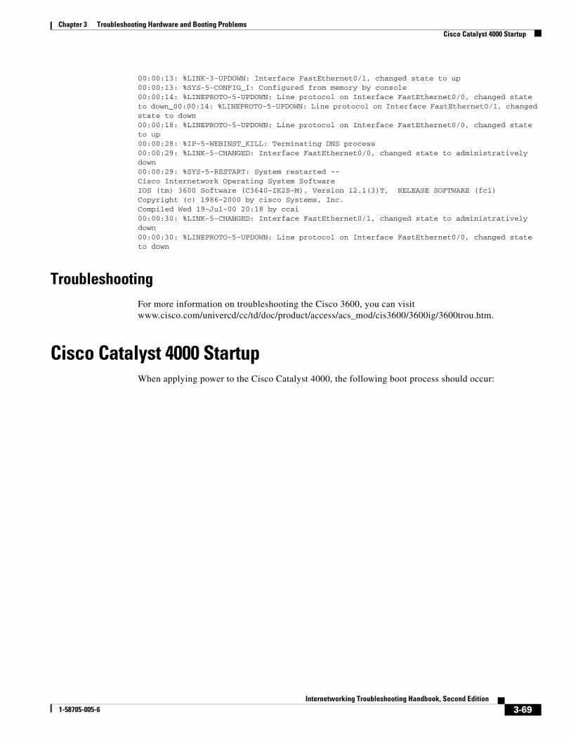
Chapter 3 Troubleshooting Hardware and Booting ProblemsCisco Catalyst 4000 Startup
00:00:13: %LINK-3-UPDOWN: Interface FastEthernet0/1, changed state to up00:00:13: %SYS-5-CONFIG_I: Configured from memory by console00:00:14: %LINEPROTO-5-UPDOWN: Line protocol on Interface FastEthernet0/0, changed state to down_00:00:14: %LINEPROTO-5-UPDOWN: Line protocol on Interface FastEthernet0/1, changed state to down00:00:18: %LINEPROTO-5-UPDOWN: Line protocol on Interface FastEthernet0/0, changed state to up00:00:28: %IP-5-WEBINST_KILL: Terminating DNS process00:00:29: %LINK-5-CHANGED: Interface FastEthernet0/0, changed state to administratively down00:00:29: %SYS-5-RESTART: System restarted --Cisco Internetwork Operating System SoftwareIOS (tm) 3600 Software (C3640-IK2S-M), Version 12.1(3)T, RELEASE SOFTWARE (fc1)Copyright (c) 1986-2000 by cisco Systems, Inc.Compiled Wed 19-Jul-00 20:18 by ccai00:00:30: %LINK-5-CHANGED: Interface FastEthernet0/1, changed state to administratively down00:00:30: %LINEPROTO-5-UPDOWN: Line protocol on Interface FastEthernet0/0, changed state to down
TroubleshootingFor more information on troubleshooting the Cisco 3600, you can visit www.cisco.com/univercd/cc/td/doc/product/access/acs_mod/cis3600/3600ig/3600trou.htm.
Cisco Catalyst 4000 StartupWhen applying power to the Cisco Catalyst 4000, the following boot process should occur:
3-69Internetworking Troubleshooting Handbook, Second Edition
1-58705-005-6
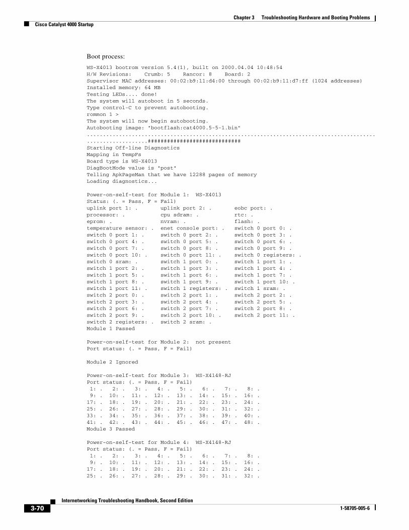
Chapter 3 Troubleshooting Hardware and Booting ProblemsCisco Catalyst 4000 Startup
Boot process:
WS-X4013 bootrom version 5.4(1), built on 2000.04.04 10:48:54H/W Revisions: Crumb: 5 Rancor: 8 Board: 2Supervisor MAC addresses: 00:02:b9:11:d4:00 through 00:02:b9:11:d7:ff (1024 addresses)Installed memory: 64 MBTesting LEDs.... done!The system will autoboot in 5 seconds.Type control-C to prevent autobooting.rommon 1 >The system will now begin autobooting.Autobooting image: "bootflash:cat4000.5-5-1.bin".............................................................................................................#############################Starting Off-line DiagnosticsMapping in TempFsBoard type is WS-X4013DiagBootMode value is "post"Telling ApkPageMan that we have 12288 pages of memoryLoading diagnostics...
Power-on-self-test for Module 1: WS-X4013Status: (. = Pass, F = Fail)uplink port 1: . uplink port 2: . eobc port: . processor: . cpu sdram: . rtc: . eprom: . nvram: . flash: . temperature sensor: . enet console port: . switch 0 port 0: . switch 0 port 1: . switch 0 port 2: . switch 0 port 3: . switch 0 port 4: . switch 0 port 5: . switch 0 port 6: . switch 0 port 7: . switch 0 port 8: . switch 0 port 9: . switch 0 port 10: . switch 0 port 11: . switch 0 registers: . switch 0 sram: . switch 1 port 0: . switch 1 port 1: . switch 1 port 2: . switch 1 port 3: . switch 1 port 4: . switch 1 port 5: . switch 1 port 6: . switch 1 port 7: . switch 1 port 8: . switch 1 port 9: . switch 1 port 10: . switch 1 port 11: . switch 1 registers: . switch 1 sram: . switch 2 port 0: . switch 2 port 1: . switch 2 port 2: . switch 2 port 3: . switch 2 port 4: . switch 2 port 5: . switch 2 port 6: . switch 2 port 7: . switch 2 port 8: . switch 2 port 9: . switch 2 port 10: . switch 2 port 11: . switch 2 registers: . switch 2 sram: . Module 1 Passed
Power-on-self-test for Module 2: not presentPort status: (. = Pass, F = Fail)
Module 2 Ignored
Power-on-self-test for Module 3: WS-X4148-RJPort status: (. = Pass, F = Fail) 1: . 2: . 3: . 4: . 5: . 6: . 7: . 8: . 9: . 10: . 11: . 12: . 13: . 14: . 15: . 16: . 17: . 18: . 19: . 20: . 21: . 22: . 23: . 24: . 25: . 26: . 27: . 28: . 29: . 30: . 31: . 32: . 33: . 34: . 35: . 36: . 37: . 38: . 39: . 40: . 41: . 42: . 43: . 44: . 45: . 46: . 47: . 48: . Module 3 Passed
Power-on-self-test for Module 4: WS-X4148-RJPort status: (. = Pass, F = Fail) 1: . 2: . 3: . 4: . 5: . 6: . 7: . 8: . 9: . 10: . 11: . 12: . 13: . 14: . 15: . 16: . 17: . 18: . 19: . 20: . 21: . 22: . 23: . 24: . 25: . 26: . 27: . 28: . 29: . 30: . 31: . 32: .
3-70Internetworking Troubleshooting Handbook, Second Edition
1-58705-005-6
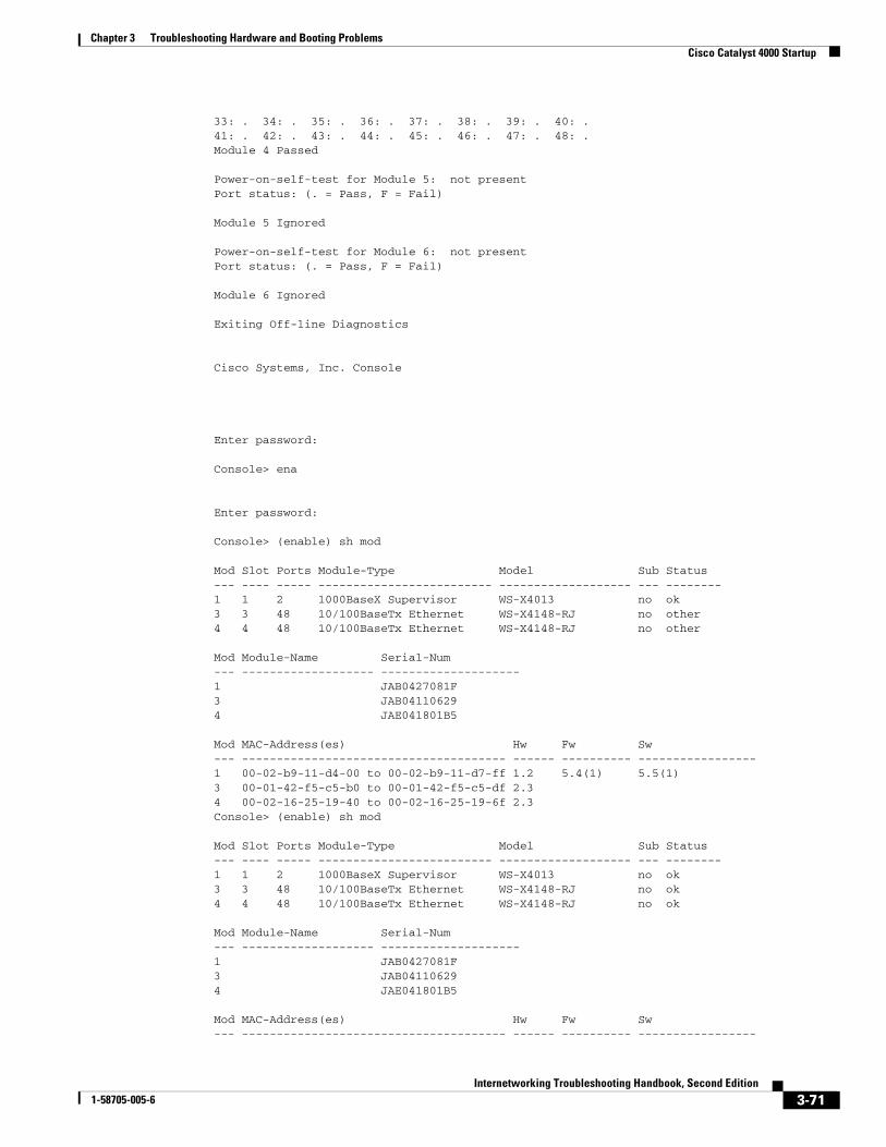
Chapter 3 Troubleshooting Hardware and Booting ProblemsCisco Catalyst 4000 Startup
33: . 34: . 35: . 36: . 37: . 38: . 39: . 40: . 41: . 42: . 43: . 44: . 45: . 46: . 47: . 48: . Module 4 Passed
Power-on-self-test for Module 5: not presentPort status: (. = Pass, F = Fail)
Module 5 Ignored
Power-on-self-test for Module 6: not presentPort status: (. = Pass, F = Fail)
Module 6 Ignored
Exiting Off-line Diagnostics
Cisco Systems, Inc. Console
Enter password:
Console> ena
Enter password:
Console> (enable) sh mod
Mod Slot Ports Module-Type Model Sub Status--- ---- ----- ------------------------- ------------------- --- --------1 1 2 1000BaseX Supervisor WS-X4013 no ok3 3 48 10/100BaseTx Ethernet WS-X4148-RJ no other4 4 48 10/100BaseTx Ethernet WS-X4148-RJ no other
Mod Module-Name Serial-Num--- ------------------- --------------------1 JAB0427081F 3 JAB04110629 4 JAE041801B5
Mod MAC-Address(es) Hw Fw Sw--- -------------------------------------- ------ ---------- -----------------1 00-02-b9-11-d4-00 to 00-02-b9-11-d7-ff 1.2 5.4(1) 5.5(1)3 00-01-42-f5-c5-b0 to 00-01-42-f5-c5-df 2.3 4 00-02-16-25-19-40 to 00-02-16-25-19-6f 2.3 Console> (enable) sh mod
Mod Slot Ports Module-Type Model Sub Status--- ---- ----- ------------------------- ------------------- --- --------1 1 2 1000BaseX Supervisor WS-X4013 no ok3 3 48 10/100BaseTx Ethernet WS-X4148-RJ no ok4 4 48 10/100BaseTx Ethernet WS-X4148-RJ no ok
Mod Module-Name Serial-Num--- ------------------- --------------------1 JAB0427081F 3 JAB04110629 4 JAE041801B5
Mod MAC-Address(es) Hw Fw Sw--- -------------------------------------- ------ ---------- -----------------
3-71Internetworking Troubleshooting Handbook, Second Edition
1-58705-005-6
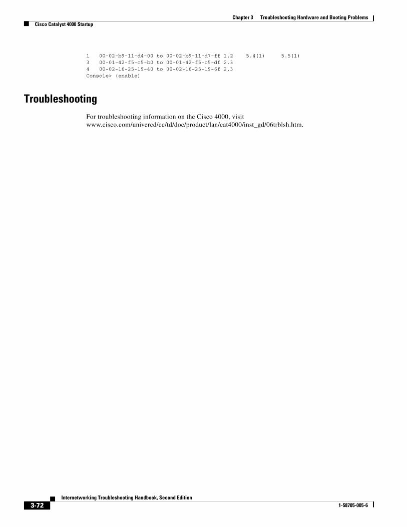
Chapter 3 Troubleshooting Hardware and Booting ProblemsCisco Catalyst 4000 Startup
1 00-02-b9-11-d4-00 to 00-02-b9-11-d7-ff 1.2 5.4(1) 5.5(1)3 00-01-42-f5-c5-b0 to 00-01-42-f5-c5-df 2.3 4 00-02-16-25-19-40 to 00-02-16-25-19-6f 2.3 Console> (enable)
TroubleshootingFor troubleshooting information on the Cisco 4000, visit www.cisco.com/univercd/cc/td/doc/product/lan/cat4000/inst_gd/06trblsh.htm.
3-72Internetworking Troubleshooting Handbook, Second Edition
1-58705-005-6