troubleshooting the home network - the greater … troubleshooting the home... · troubleshooting...
TRANSCRIPT
Troubleshooting the Home Network Mark Ortel System Engineer Communication Test & Measurement JDSU Cable Network Division
Member and Supporter
© 2005 JDSU. All rights reserved. JDSU CONFIDENTIAL & PROPRIETARY INFORMATION 2
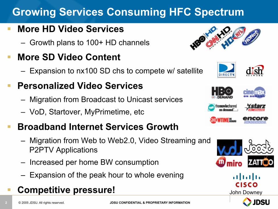
Growing Services Consuming HFC Spectrum § More HD Video Services
– Growth plans to 100+ HD channels
§ More SD Video Content – Expansion to nx100 SD chs to compete w/ satellite
§ Personalized Video Services – Migration from Broadcast to Unicast services – VoD, Startover, MyPrimetime, etc
§ Broadband Internet Services Growth – Migration from Web to Web2.0, Video Streaming and
P2PTV Applications – Increased per home BW consumption – Expansion of the peak hour to whole evening
§ Competitive pressure! John Downey
© 2005 JDSU. All rights reserved. JDSU CONFIDENTIAL & PROPRIETARY INFORMATION 3
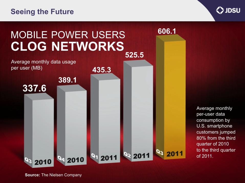
337.6
MOBILE POWER USERS CLOG NETWORKS
389.1 435.3
525.5
606.1
Seeing the Future
Average monthly data usage per user (MB)
Average monthly per-user data consumption by U.S. smartphone customers jumped 80% from the third quarter of 2010 to the third quarter of 2011.
Source: The Nielsen Company

© 2005 JDSU. All rights reserved. JDSU CONFIDENTIAL & PROPRIETARY INFORMATION 4
Seeing the Future
Source: Pipeline Magazine
STREAMING VIDEO DOMINATES WEB TRAFFIC
Nearly60% by 2015
© 2005 JDSU. All rights reserved. JDSU CONFIDENTIAL & PROPRIETARY INFORMATION 5
Seeing The Future
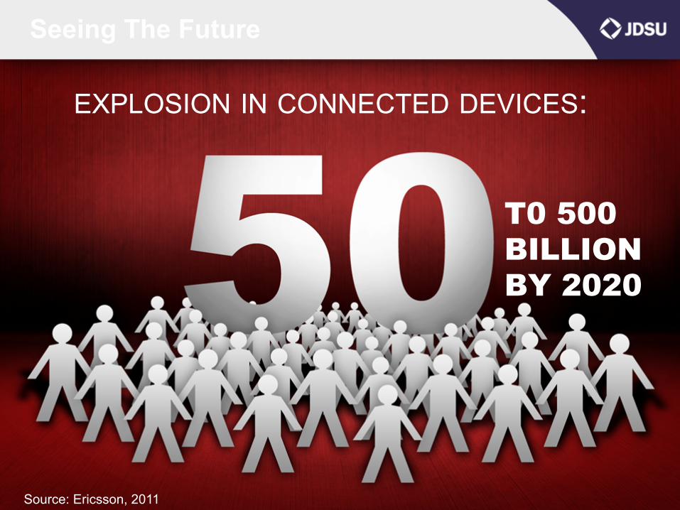
EXPLOSION IN CONNECTED DEVICES:
Source: Ericsson, 2011
T0 500 BILLION BY 2020
© 2005 JDSU. All rights reserved. JDSU CONFIDENTIAL & PROPRIETARY INFORMATION 6
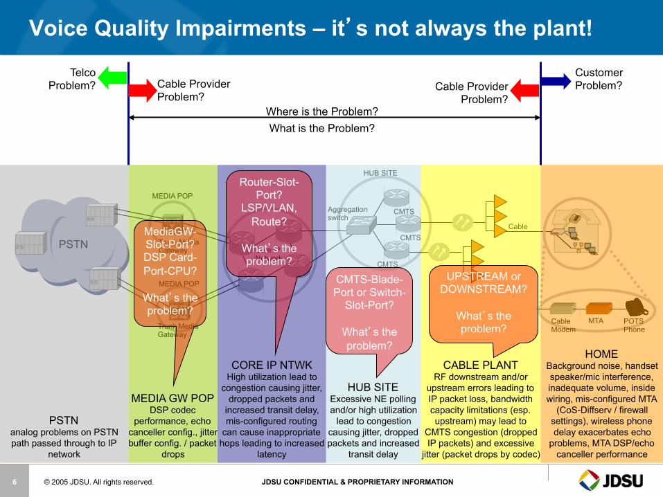
Voice Quality Impairments – it’s not always the plant!
PSTN
Cable
CMTS
CMTS
CMTS
Aggregation switch
Core IP Network
HUB SITE
MEDIA POP
MEDIA POP
Trunk Media Gateway
Trunk Media Gateway
Cable Modem
MTA POTS Phone
HOME Background noise, handset speaker/mic interference, inadequate volume, inside wiring, mis-configured MTA
(CoS-Diffserv / firewall settings), wireless phone delay exacerbates echo
problems, MTA DSP/echo canceller performance
CABLE PLANT RF downstream and/or
upstream errors leading to IP packet loss, bandwidth capacity limitations (esp. upstream) may lead to
CMTS congestion (dropped IP packets) and excessive
jitter (packet drops by codec)
Customer Problem? Cable Provider
Problem?
HUB SITE Excessive NE polling and/or high utilization
lead to congestion causing jitter, dropped packets and increased
transit delay
UPSTREAM or DOWNSTREAM?
What’s the problem?
CORE IP NTWK High utilization lead to
congestion causing jitter, dropped packets and
increased transit delay, mis-configured routing
can cause inappropriate hops leading to increased
latency
MEDIA GW POP DSP codec
performance, echo canceller config., jitter buffer config. / packet
drops
Telco Problem?
PSTN analog problems on PSTN path passed through to IP
network
Cable Provider Problem?
Where is the Problem? What is the Problem?
CMTS-Blade-Port or Switch-
Slot-Port?
What’s the problem?
Router-Slot-Port?
LSP/VLAN, Route?
What’s the problem?
MediaGW-Slot-Port? DSP Card-Port-CPU?
What’s the problem?
© 2005 JDSU. All rights reserved. JDSU CONFIDENTIAL & PROPRIETARY INFORMATION 7
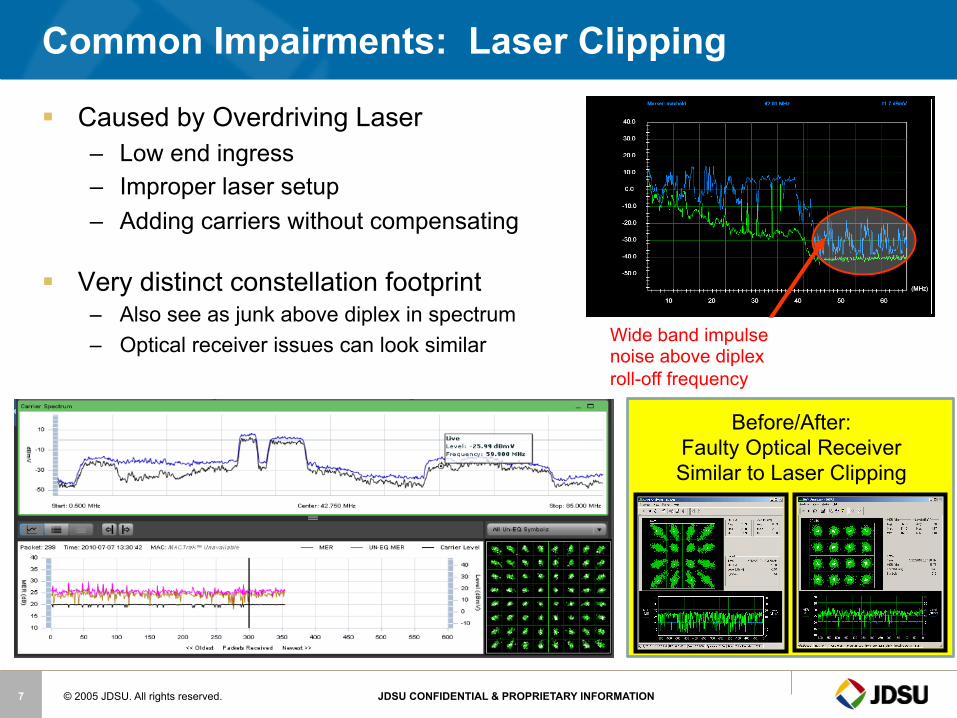
Common Impairments: Laser Clipping
§ Caused by Overdriving Laser – Low end ingress – Improper laser setup – Adding carriers without compensating
§ Very distinct constellation footprint – Also see as junk above diplex in spectrum – Optical receiver issues can look similar
Before/After: Faulty Optical Receiver Similar to Laser Clipping
Wide band impulse noise above diplex roll-off frequency

© 2005 JDSU. All rights reserved. JDSU CONFIDENTIAL & PROPRIETARY INFORMATION 8
§ RF level is too high at input of return laser – Verify light level at input of return optical receiver – Verify RF level at input of return laser – Verify RF spectrum above diplex frequency at input of return laser
30 MHz 60 MHz 36 MHz 72 MHz
Optical Link is Critical to Upstream Performance
WebView v2.5 FFT View of the Upstream
© 2005 JDSU. All rights reserved. JDSU CONFIDENTIAL & PROPRIETARY INFORMATION 9
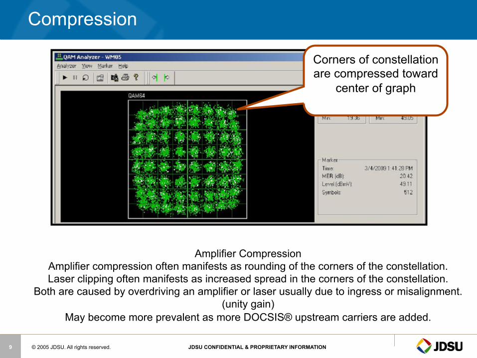
Amplifier Compression Amplifier compression often manifests as rounding of the corners of the constellation. Laser clipping often manifests as increased spread in the corners of the constellation.
Both are caused by overdriving an amplifier or laser usually due to ingress or misalignment. (unity gain)
May become more prevalent as more DOCSIS® upstream carriers are added.
Compression
Corners of constellation are compressed toward
center of graph
© 2005 JDSU. All rights reserved. JDSU CONFIDENTIAL & PROPRIETARY INFORMATION 10
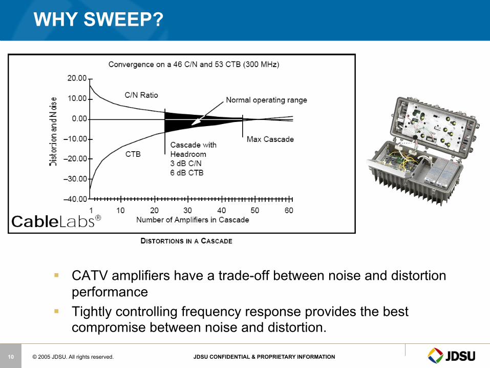
§ CATV amplifiers have a trade-off between noise and distortion performance
§ Tightly controlling frequency response provides the best compromise between noise and distortion.
WHY SWEEP?
© 2005 JDSU. All rights reserved. JDSU CONFIDENTIAL & PROPRIETARY INFORMATION 11
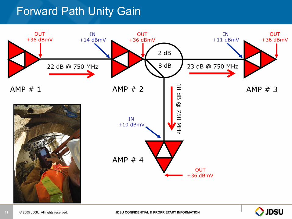
Forward Path Unity Gain
OUT +36 dBmV
OUT +36 dBmV
OUT +36 dBmV
OUT +36 dBmV
AMP # 1 AMP # 2 AMP # 3
AMP # 4
IN +14 dBmV
IN +11 dBmV
IN +10 dBmV
2 dB
8 dB 22 dB @ 750 MHz 23 dB @ 750 MHz
18 dB @
750 MH
z

© 2005 JDSU. All rights reserved. JDSU CONFIDENTIAL & PROPRIETARY INFORMATION 12
Incorrect Levels
§ Low Video Levels § Produces noise in
the picture
• High Video Levels
Produces distortion in the picture
© 2005 JDSU. All rights reserved. JDSU CONFIDENTIAL & PROPRIETARY INFORMATION 13
Low Digital levels
§ Causes Digital signal to Degrade.
§ This causes Tiling and Loss
of high Speed internet access.
© 2005 JDSU. All rights reserved. JDSU CONFIDENTIAL & PROPRIETARY INFORMATION 14
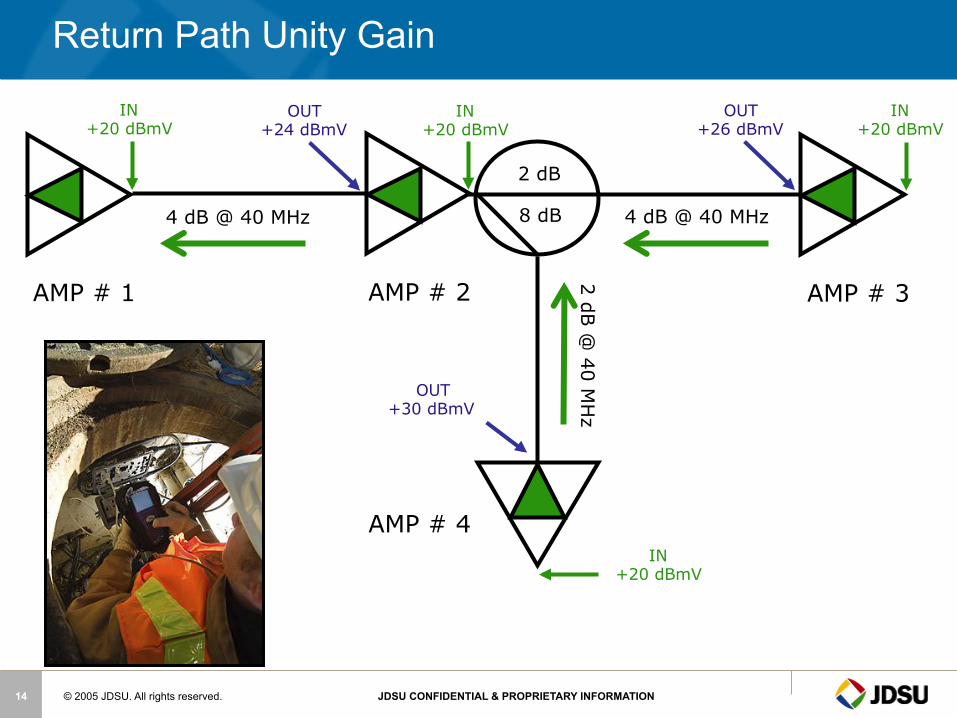
Return Path Unity Gain
AMP # 1 AMP # 2 AMP # 3
AMP # 4
OUT +30 dBmV
2 dB
8 dB
IN +20 dBmV
IN +20 dBmV
IN +20 dBmV
OUT +24 dBmV
OUT +26 dBmV
IN +20 dBmV
4 dB @ 40 MHz 4 dB @ 40 MHz
2 dB @
40 MH
z
© 2005 JDSU. All rights reserved. JDSU CONFIDENTIAL & PROPRIETARY INFORMATION 15
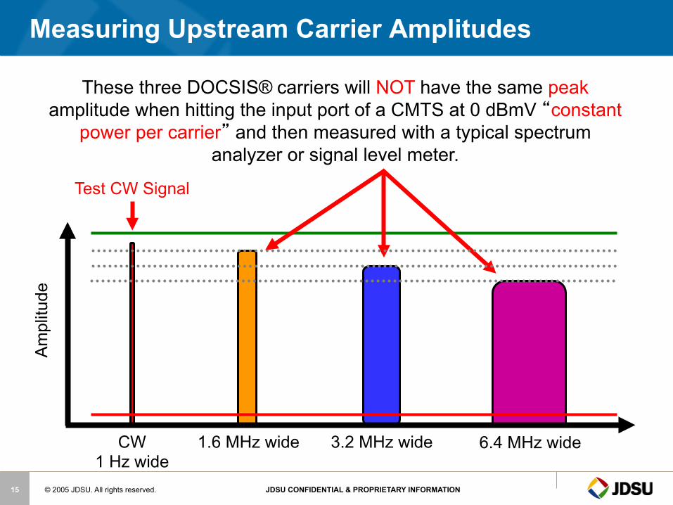
Measuring Upstream Carrier Amplitudes A
mpl
itude
3.2 MHz wide 6.4 MHz wide 1.6 MHz wide CW 1 Hz wide
Test CW Signal
These three DOCSIS® carriers will NOT have the same peak amplitude when hitting the input port of a CMTS at 0 dBmV “constant
power per carrier” and then measured with a typical spectrum analyzer or signal level meter.
© 2005 JDSU. All rights reserved. JDSU CONFIDENTIAL & PROPRIETARY INFORMATION 16
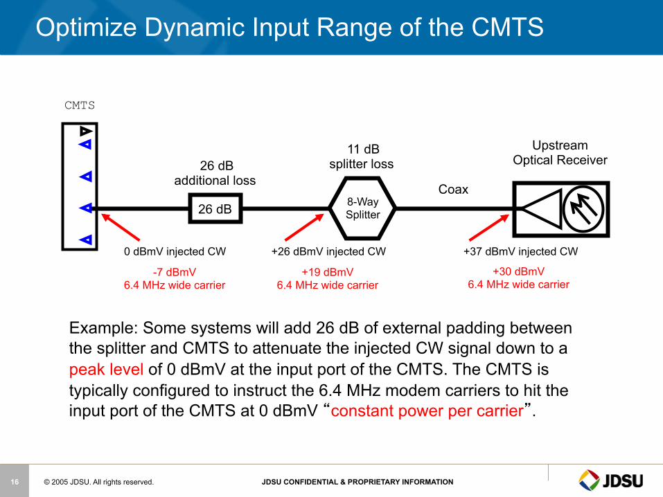
Optimize Dynamic Input Range of the CMTS
26 dB
26 dB additional loss
Upstream Optical Receiver
8-Way Splitter
Coax
Example: Some systems will add 26 dB of external padding between the splitter and CMTS to attenuate the injected CW signal down to a peak level of 0 dBmV at the input port of the CMTS. The CMTS is typically configured to instruct the 6.4 MHz modem carriers to hit the input port of the CMTS at 0 dBmV “constant power per carrier”.
11 dB splitter loss
+37 dBmV injected CW
+30 dBmV 6.4 MHz wide carrier
+26 dBmV injected CW
+19 dBmV 6.4 MHz wide carrier
0 dBmV injected CW
-7 dBmV 6.4 MHz wide carrier
CMTS

Docsis 3

© 2005 JDSU. All rights reserved. JDSU CONFIDENTIAL & PROPRIETARY INFORMATION 18
Maximum and (Maximum Usable)DownStream Speeds
Downstream Version DOCSIS EuroDOCSIS
1.x 42.88 (38) Mbit/s
55.62 (50) Mbit/s
2.0 42.88 (38) Mbit/s
55.62 (50) Mbit/s
3.0 ----------4 channel
171.52 (+152) Mbit/s
+222.48 (+200) Mbit/s
3.0 ----------8 channel
+343.04 (+304) Mbit/s
+444.96 (+400) Mbit/s
© 2005 JDSU. All rights reserved. JDSU CONFIDENTIAL & PROPRIETARY INFORMATION 19
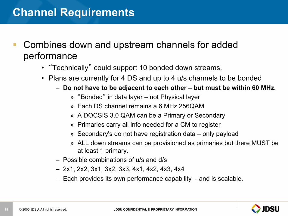
Channel Requirements
§ Combines down and upstream channels for added performance
• “Technically” could support 10 bonded down streams. • Plans are currently for 4 DS and up to 4 u/s channels to be bonded
– Do not have to be adjacent to each other – but must be within 60 MHz. » “Bonded” in data layer – not Physical layer » Each DS channel remains a 6 MHz 256QAM » A DOCSIS 3.0 QAM can be a Primary or Secondary » Primaries carry all info needed for a CM to register » Secondary's do not have registration data – only payload » ALL down streams can be provisioned as primaries but there MUST be
at least 1 primary. – Possible combinations of u/s and d/s – 2x1, 2x2, 3x1, 3x2, 3x3, 4x1, 4x2, 4x3, 4x4 – Each provides its own performance capability - and is scalable.

© 2005 JDSU. All rights reserved. JDSU CONFIDENTIAL & PROPRIETARY INFORMATION 20
Un-Bonded Upstream Data rates
§ Courtesy Motorola

© 2005 JDSU. All rights reserved. JDSU CONFIDENTIAL & PROPRIETARY INFORMATION 21
SCTE Downstream Modem Configuration
Source: SCTE
© 2005 JDSU. All rights reserved. JDSU CONFIDENTIAL & PROPRIETARY INFORMATION 22
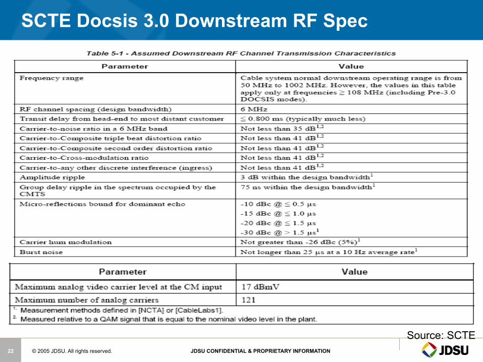
SCTE Docsis 3.0 Downstream RF Spec
Source: SCTE
© 2005 JDSU. All rights reserved. JDSU CONFIDENTIAL & PROPRIETARY INFORMATION 23
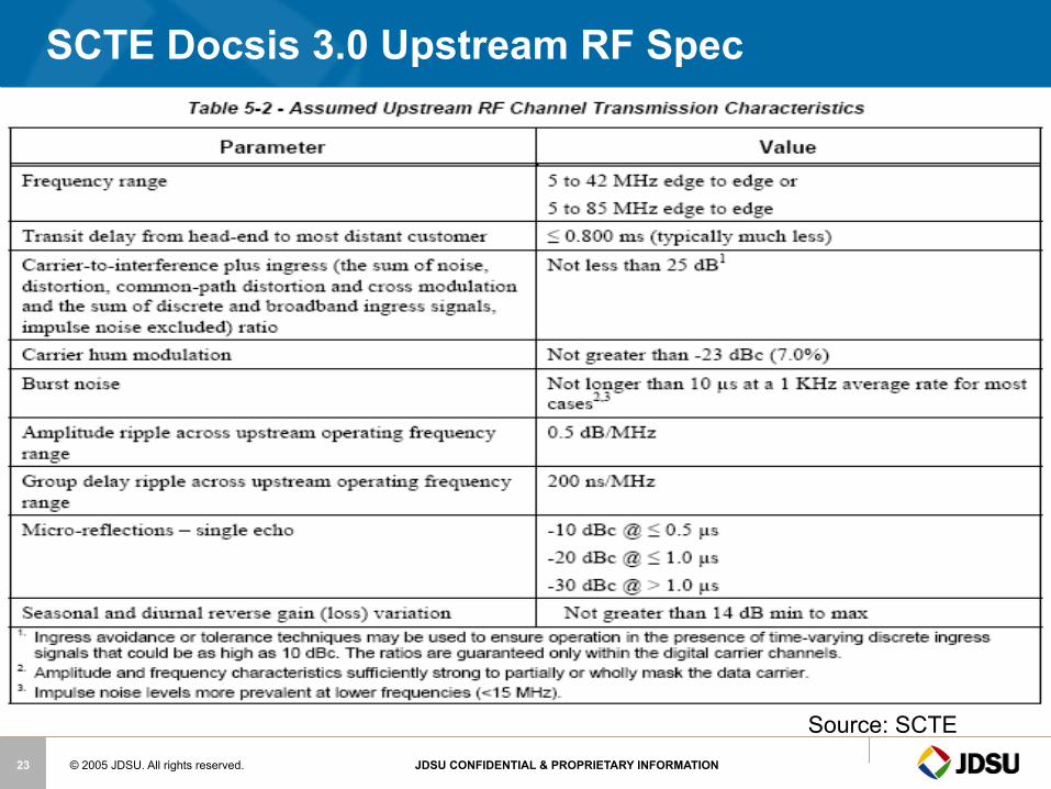
SCTE Docsis 3.0 Upstream RF Spec
Source: SCTE
© 2005 JDSU. All rights reserved. JDSU CONFIDENTIAL & PROPRIETARY INFORMATION 24
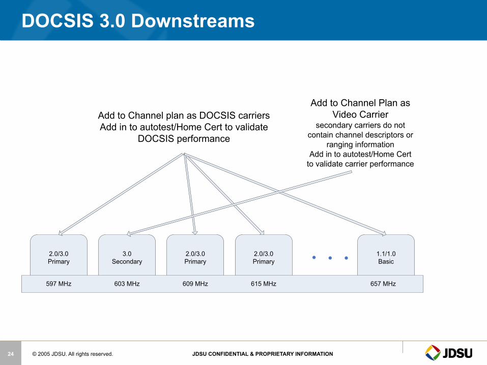
DOCSIS 3.0 Downstreams
2.0/3.0Primary
3.0Secondary
2.0/3.0Primary
2.0/3.0Primary
1.1/1.0Basic
597 MHz 603 MHz 609 MHz 615 MHz 657 MHz
Add to Channel plan as DOCSIS carriersAdd in to autotest/Home Cert to validate
DOCSIS performance
Add to Channel Plan as Video Carrier
secondary carriers do not contain channel descriptors or
ranging informationAdd in to autotest/Home Cert
to validate carrier performance

© 2005 JDSU. All rights reserved. JDSU CONFIDENTIAL & PROPRIETARY INFORMATION 25
DSAM 3.0 Bonded Carrier testing – coming soon
§ Keeping it simple for the technicians
§ Validate overall performance
§ Identifying individual US/DS channel issues

Customer Networks
© 2005 JDSU. All rights reserved. JDSU CONFIDENTIAL & PROPRIETARY INFORMATION 27
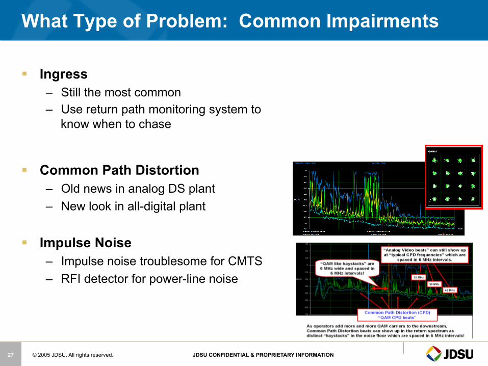
What Type of Problem: Common Impairments
§ Ingress – Still the most common – Use return path monitoring system to
know when to chase
§ Common Path Distortion – Old news in analog DS plant – New look in all-digital plant
§ Impulse Noise – Impulse noise troublesome for CMTS – RFI detector for power-line noise
© 2005 JDSU. All rights reserved. JDSU CONFIDENTIAL & PROPRIETARY INFORMATION 28
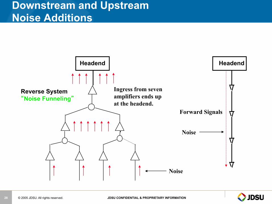
Headend Headend
Reverse System “Noise Funneling”
Ingress from seven amplifiers ends up at the headend.
Forward Signals
Noise
Noise
Downstream and Upstream Noise Additions

© 2005 JDSU. All rights reserved. JDSU CONFIDENTIAL & PROPRIETARY INFORMATION 29
Testing for Ingress on Forward Digital Carriers
© 2005 JDSU. All rights reserved. JDSU CONFIDENTIAL & PROPRIETARY INFORMATION 30
What Causes Signal Leakage & Ingress?
§ Most common source of leakage is within the home wiring (approximately 75%) and drop cable (approximately 20%). There’s a lot of homes that still have the original wiring from 20-30 years ago!
§ Inferior quality coaxial cable, passives, connectors
§ Poor installation of splices and connectors - water and weather can result in pulled out, loose or corroded connectors
§ Illegal connections to neighbor’s cable
§ Some of the older TV sets with poor tuner shielding can produce leakage and ingress problems
© 2005 JDSU. All rights reserved. JDSU CONFIDENTIAL & PROPRIETARY INFORMATION 31
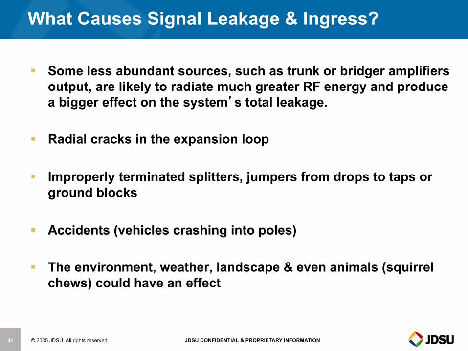
§ Some less abundant sources, such as trunk or bridger amplifiers output, are likely to radiate much greater RF energy and produce a bigger effect on the system’s total leakage.
§ Radial cracks in the expansion loop
§ Improperly terminated splitters, jumpers from drops to taps or ground blocks
§ Accidents (vehicles crashing into poles)
§ The environment, weather, landscape & even animals (squirrel chews) could have an effect
What Causes Signal Leakage & Ingress?
© 2005 JDSU. All rights reserved. JDSU CONFIDENTIAL & PROPRIETARY INFORMATION 32
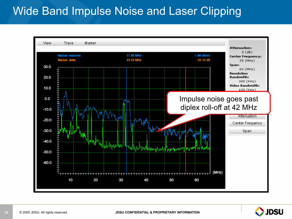
Wide Band Impulse Noise and Laser Clipping
Impulse noise goes past diplex roll-off at 42 MHz
© 2005 JDSU. All rights reserved. JDSU CONFIDENTIAL & PROPRIETARY INFORMATION 33
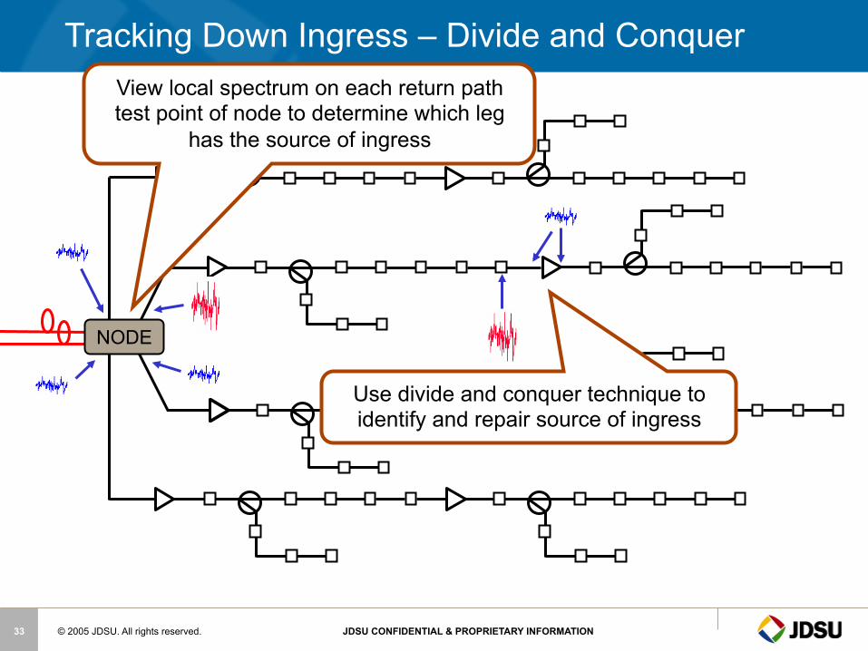
NODE
Tracking Down Ingress – Divide and Conquer View local spectrum on each return path test point of node to determine which leg
has the source of ingress
Use divide and conquer technique to identify and repair source of ingress

© 2005 JDSU. All rights reserved. JDSU CONFIDENTIAL & PROPRIETARY INFORMATION 34
Typical Problem Areas
§ Taps – Most ingress comes from houses off of with low value taps
of approximately 17 dB or less
§ Home Wiring – Drop Cable, splitters & F Connectors are approximately
~95% of Problem
§ Amplifiers, hard line cable and the rest of the system are a small percentage of the problem if a proper leakage maintenance program is performed
low value taps low value taps
© 2005 JDSU. All rights reserved. JDSU CONFIDENTIAL & PROPRIETARY INFORMATION 35
Return Path
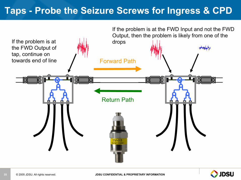
Taps - Probe the Seizure Screws for Ingress & CPD
If the problem is at the FWD Input and not the FWD Output, then the problem is likely from one of the drops If the problem is at
the FWD Output of tap, continue on towards end of line Forward Path
© 2005 JDSU. All rights reserved. JDSU CONFIDENTIAL & PROPRIETARY INFORMATION 36
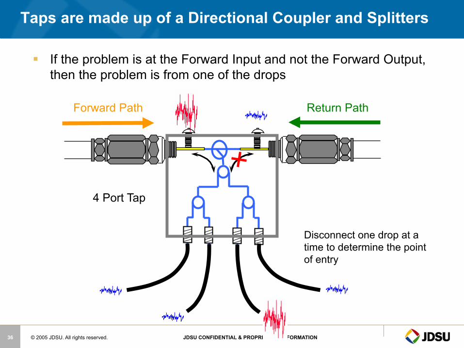
4 Port Tap
Taps are made up of a Directional Coupler and Splitters
Disconnect one drop at a time to determine the point of entry
§ If the problem is at the Forward Input and not the Forward Output, then the problem is from one of the drops
Forward Path Return Path

© 2005 JDSU. All rights reserved. JDSU CONFIDENTIAL & PROPRIETARY INFORMATION 37
Common problems in HFC Networks
© 2005 JDSU. All rights reserved. JDSU CONFIDENTIAL & PROPRIETARY INFORMATION 38
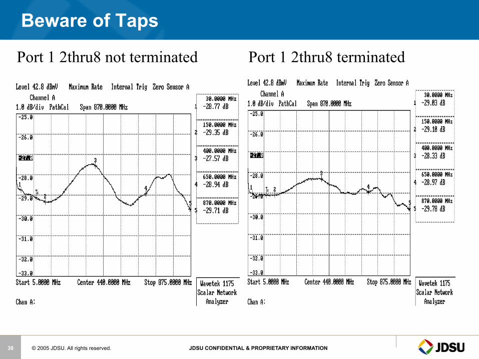
Beware of Taps
Port 1 2thru8 not terminated Port 1 2thru8 terminated

© 2005 JDSU. All rights reserved. JDSU CONFIDENTIAL & PROPRIETARY INFORMATION 39
RF ingress — The 5-42 MHz reverse spectrum is shared with numerous over-the-air users.
Signals in the over-the-air environment include high power shortwave broadcasts, amateur radio, citizens band, government, and other two-way radio communications.
Reverse Path Impairments - Ingress
© 2005 JDSU. All rights reserved. JDSU CONFIDENTIAL & PROPRIETARY INFORMATION 40
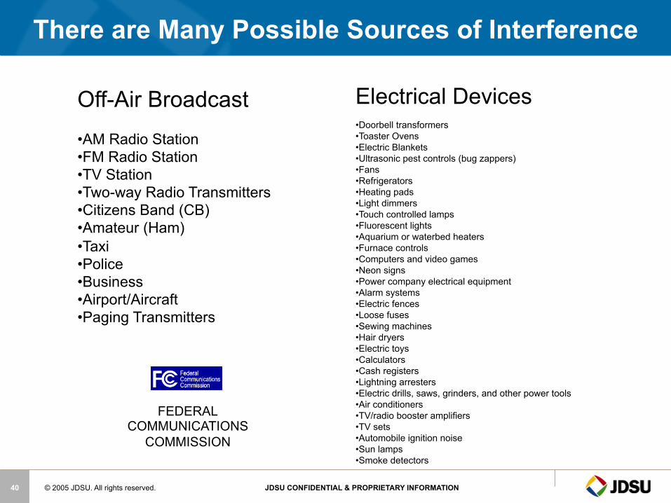
Electrical Devices
• Doorbell transformers • Toaster Ovens • Electric Blankets • Ultrasonic pest controls (bug zappers) • Fans • Refrigerators • Heating pads • Light dimmers • Touch controlled lamps • Fluorescent lights • Aquarium or waterbed heaters • Furnace controls • Computers and video games • Neon signs • Power company electrical equipment • Alarm systems • Electric fences • Loose fuses • Sewing machines • Hair dryers • Electric toys • Calculators • Cash registers • Lightning arresters • Electric drills, saws, grinders, and other power tools • Air conditioners • TV/radio booster amplifiers • TV sets • Automobile ignition noise • Sun lamps • Smoke detectors
There are Many Possible Sources of Interference
Off-Air Broadcast
• AM Radio Station • FM Radio Station • TV Station • Two-way Radio Transmitters • Citizens Band (CB) • Amateur (Ham) • Taxi • Police • Business • Airport/Aircraft • Paging Transmitters
FEDERAL COMMUNICATIONS
COMMISSION
© 2005 JDSU. All rights reserved. JDSU CONFIDENTIAL & PROPRIETARY INFORMATION 41
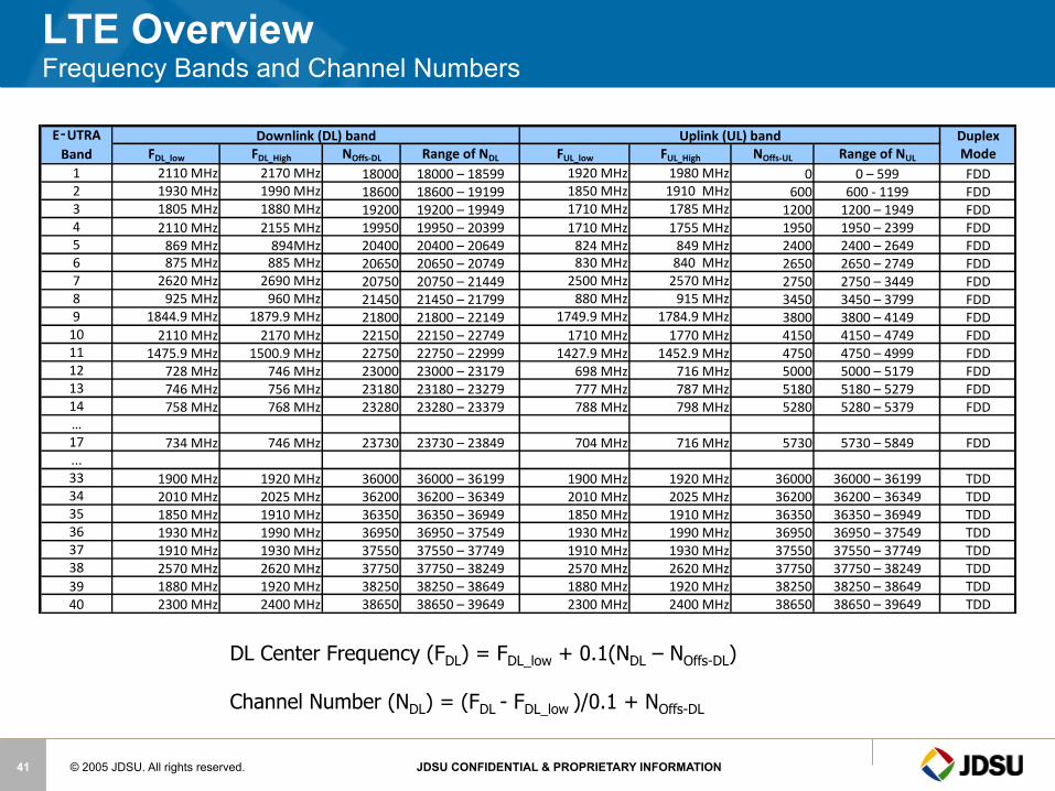
LTE Overview Frequency Bands and Channel Numbers
Duplex FDL_low FDL_High NOffs-‐DL Range of NDL FUL_low FUL_High NOffs-‐UL Range of NUL Mode
1 2110 MHz 2170 MHz 18000 18000 – 18599 1920 MHz 1980 MHz 0 0 – 599 FDD2 1930 MHz 1990 MHz 18600 18600 – 19199 1850 MHz 1910 MHz 600 600 -‐ 1199 FDD3 1805 MHz 1880 MHz 19200 19200 – 19949 1710 MHz 1785 MHz 1200 1200 – 1949 FDD4 2110 MHz 2155 MHz 19950 19950 – 20399 1710 MHz 1755 MHz 1950 1950 – 2399 FDD5 869 MHz 894MHz 20400 20400 – 20649 824 MHz 849 MHz 2400 2400 – 2649 FDD6 875 MHz 885 MHz 20650 20650 – 20749 830 MHz 840 MHz 2650 2650 – 2749 FDD7 2620 MHz 2690 MHz 20750 20750 – 21449 2500 MHz 2570 MHz 2750 2750 – 3449 FDD8 925 MHz 960 MHz 21450 21450 – 21799 880 MHz 915 MHz 3450 3450 – 3799 FDD9 1844.9 MHz 1879.9 MHz 21800 21800 – 22149 1749.9 MHz 1784.9 MHz 3800 3800 – 4149 FDD10 2110 MHz 2170 MHz 22150 22150 – 22749 1710 MHz 1770 MHz 4150 4150 – 4749 FDD11 1475.9 MHz 1500.9 MHz 22750 22750 – 22999 1427.9 MHz 1452.9 MHz 4750 4750 – 4999 FDD12 728 MHz 746 MHz 23000 23000 – 23179 698 MHz 716 MHz 5000 5000 – 5179 FDD13 746 MHz 756 MHz 23180 23180 – 23279 777 MHz 787 MHz 5180 5180 – 5279 FDD14 758 MHz 768 MHz 23280 23280 – 23379 788 MHz 798 MHz 5280 5280 – 5379 FDD…17 734 MHz 746 MHz 23730 23730 – 23849 704 MHz 716 MHz 5730 5730 – 5849 FDD...33 1900 MHz 1920 MHz 36000 36000 – 36199 1900 MHz 1920 MHz 36000 36000 – 36199 TDD34 2010 MHz 2025 MHz 36200 36200 – 36349 2010 MHz 2025 MHz 36200 36200 – 36349 TDD35 1850 MHz 1910 MHz 36350 36350 – 36949 1850 MHz 1910 MHz 36350 36350 – 36949 TDD36 1930 MHz 1990 MHz 36950 36950 – 37549 1930 MHz 1990 MHz 36950 36950 – 37549 TDD37 1910 MHz 1930 MHz 37550 37550 – 37749 1910 MHz 1930 MHz 37550 37550 – 37749 TDD38 2570 MHz 2620 MHz 37750 37750 – 38249 2570 MHz 2620 MHz 37750 37750 – 38249 TDD39 1880 MHz 1920 MHz 38250 38250 – 38649 1880 MHz 1920 MHz 38250 38250 – 38649 TDD40 2300 MHz 2400 MHz 38650 38650 – 39649 2300 MHz 2400 MHz 38650 38650 – 39649 TDD
Uplink (UL) bandDownlink (DL) bandE‑UTRA Band
DL Center Frequency (FDL) = FDL_low + 0.1(NDL – NOffs-DL) Channel Number (NDL) = (FDL - FDL_low )/0.1 + NOffs-DL
© 2005 JDSU. All rights reserved. JDSU CONFIDENTIAL & PROPRIETARY INFORMATION 42
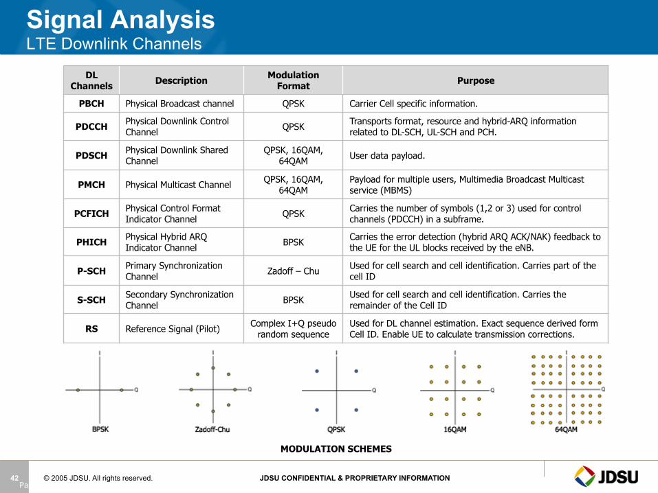
Signal Analysis LTE Downlink Channels
DL Channels Description Modulation
Format Purpose
PBCH Physical Broadcast channel QPSK Carrier Cell specific information.
PDCCH Physical Downlink Control Channel QPSK Transports format, resource and hybrid-ARQ information
related to DL-SCH, UL-SCH and PCH.
PDSCH Physical Downlink Shared Channel
QPSK, 16QAM, 64QAM User data payload.
PMCH Physical Multicast Channel QPSK, 16QAM, 64QAM
Payload for multiple users, Multimedia Broadcast Multicast service (MBMS)
PCFICH Physical Control Format Indicator Channel QPSK Carries the number of symbols (1,2 or 3) used for control
channels (PDCCH) in a subframe.
PHICH Physical Hybrid ARQ Indicator Channel BPSK Carries the error detection (hybrid ARQ ACK/NAK) feedback to
the UE for the UL blocks received by the eNB.
P-SCH Primary Synchronization Channel Zadoff – Chu Used for cell search and cell identification. Carries part of the
cell ID
S-SCH Secondary Synchronization Channel BPSK Used for cell search and cell identification. Carries the
remainder of the Cell ID
RS Reference Signal (Pilot) Complex I+Q pseudo random sequence
Used for DL channel estimation. Exact sequence derived form Cell ID. Enable UE to calculate transmission corrections.
Page 42
MODULATION SCHEMES
© 2005 JDSU. All rights reserved. JDSU CONFIDENTIAL & PROPRIETARY INFORMATION 43
In-Home Wiring is a Challenge
§ Each home is a “headend” for the reverse path § Home wiring frequently has inferior components
and craftsmanship § Replacing all home wiring is economically
unacceptable, § Each year the cable industry buys somewhere in
the neighborhood of 2 billion feet of drop cable.
© 2005 JDSU. All rights reserved. JDSU CONFIDENTIAL & PROPRIETARY INFORMATION 44
§ The subscriber drop remains the weakest link in the cable network
§ Seven out of ten service calls are generated by problems at the drop
§ Ingress caused in the home wreaks havoc on the reverse path – Must be found in the home before connecting to network when
possible – Must be monitored continuously and eliminated quickly
§ Replacing all home wiring is economically unacceptable, testing is required to find faults and bring the home wiring up to standards necessary for new services.
In-Home Wiring Is A Potentially Large Stumbling Block

© 2005 JDSU. All rights reserved. JDSU CONFIDENTIAL & PROPRIETARY INFORMATION 45
§ Kinked or damaged cable (including cracked cable, which causes a reflection and ingress)
§ Use of staples that perforate or compress coaxial cable resulting in impedance mismatches
§ Cable-ready TVs and VCRs connected directly to the drop (Return loss on most cable-ready devices is poor)
§ Older splitters and amplifiers may not be rated for 750MHz, 860MHz or 1GHz
§ Some traps and filters have been found to have poor return loss in the upstream, especially those used for data-only service
Common Problems Typically Identified in the Drop
© 2005 JDSU. All rights reserved. JDSU CONFIDENTIAL & PROPRIETARY INFORMATION 46
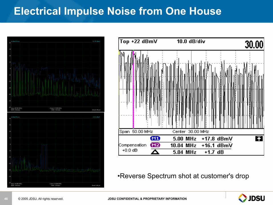
Electrical Impulse Noise from One House
-60
-50
-40
-30
-20
-10
0
10
20
30
40
Center: 25.000 MHzSpan: 40.000 MHzRBW: 300 KHz VBW: 100 KHz Dwell: 400 µS
In-Band Power 10.393 dBmV
-60
-50
-40
-30
-20
-10
0
10
20
30
40
Center: 25.000 MHzSpan: 40.000 MHzRBW: 300 KHz VBW: 100 KHz Dwell: 400 µS
In-Band Power 8.632 dBmV
• Reverse Spectrum shot at customer's drop

© 2005 JDSU. All rights reserved. JDSU CONFIDENTIAL & PROPRIETARY INFORMATION 47
Tools for Troubleshooting
– View 4MHz – 1GHz, in either 10 or 50 MHz spans, without changing modes
– While viewing return spectrum; enable a Low Pass Filter • Cuts out the higher frequency noise • Cleaner return path view; lower noise floor
– Increase Dwell time (1-25ms) per frequency scan • Find intermittent impairments better/quicker
– Adjust resolution bandwidth (RBW) from 330KHz to 30KHz • Shows more spectrum characteristics with smaller spectral
slices adding to the overall resolution
Users can now adjust the spectrum mode to better see intermittent ingress, harmonics, and other channel anomalies. They can also look over both the upstream and downstream spectrums in one mode as well as isolate the return path from the forward path, eliminating noise leaking down into the return path.
*All HW versions

© 2005 JDSU. All rights reserved. JDSU CONFIDENTIAL & PROPRIETARY INFORMATION 48
eMTA-CABLE MODEM
7 dB TAP
Drop Cable
High Pass Filter GROUND
BLOCK
3-Way Splitter
DIGITAL SET-TOP
House
2-Way Amplifier
Testing the Home for Ingress Contribution
VoIP
OLDER TV SET
Return Equalizer
ONLINE GAMING
WIRELESS LAPTOP
COMPUTOR
ETHERNET
Disconnect drop from tap and check for ingress
coming from customer’s home wiring
INGRESS SPECTRUM MEASUREMENTS
If ingress is detected, scan spectrum at ground block
for ingress

© 2005 JDSU. All rights reserved. JDSU CONFIDENTIAL & PROPRIETARY INFORMATION 49
Ingress - CB Radio
CB Radio
© 2005 JDSU. All rights reserved. JDSU CONFIDENTIAL & PROPRIETARY INFORMATION 50
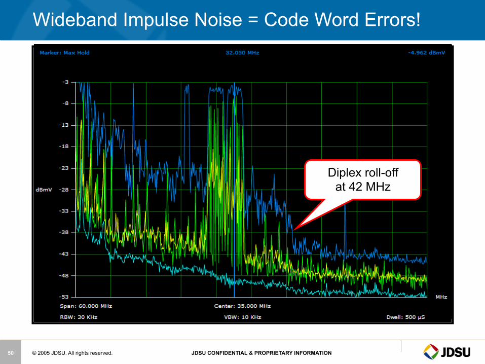
Wideband Impulse Noise = Code Word Errors!
Diplex roll-off at 42 MHz

© 2005 JDSU. All rights reserved. JDSU CONFIDENTIAL & PROPRIETARY INFORMATION 51
Wide Band Impulse Noise and Laser Clipping
Impulse noise goes past diplex roll-off at 42 MHz
© 2005 JDSU. All rights reserved. JDSU CONFIDENTIAL & PROPRIETARY INFORMATION 52
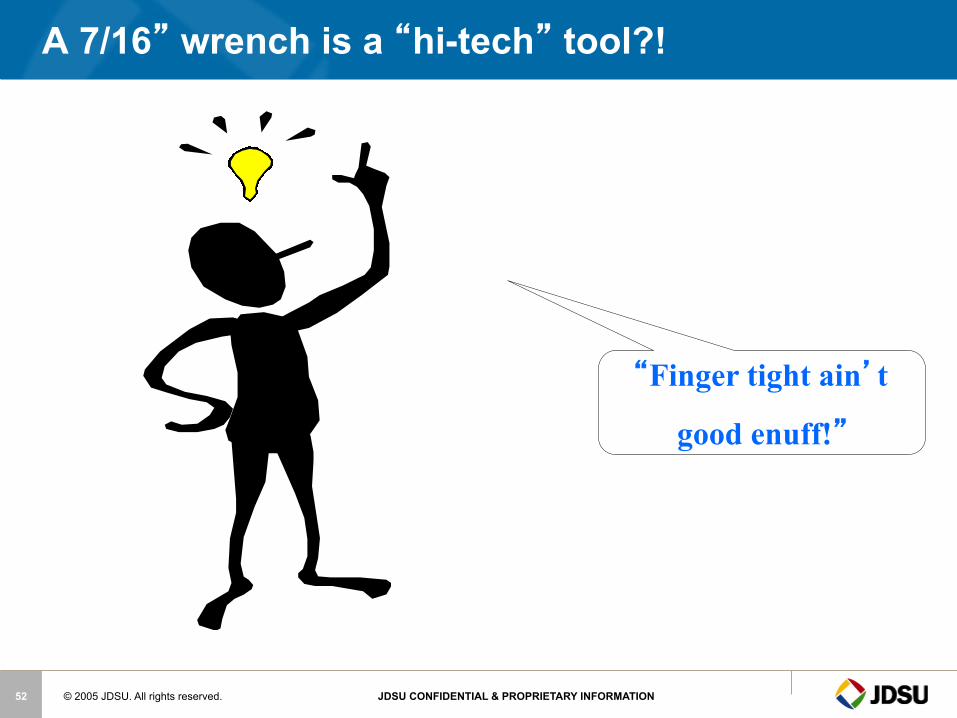
“Finger tight ain’t
good enuff!”
A 7/16” wrench is a “hi-tech” tool?!

Home Networks
© 2005 JDSU. All rights reserved. JDSU CONFIDENTIAL & PROPRIETARY INFORMATION 54
Home Networking Technologies
§ Ethernet – Runs on Cat-5 – Less than 5% of Homes wired for Ethernet
§ MoCA™ Multimedia over Coax Alliance – Runs on existing Coax
§ HPNAv3 Home Phone Network Alliance – Runs on Coax OR over existing phone lines
§ HomePlug® A/V – Runs over AC wiring
§ Proprietary over coax – TV Net(Coaxsys)/HomeRan(TMT Networks)
§ Wireless 802.11 b/g/a – Range limited due to propagation through walls
© 2005 JDSU. All rights reserved. JDSU CONFIDENTIAL & PROPRIETARY INFORMATION 55
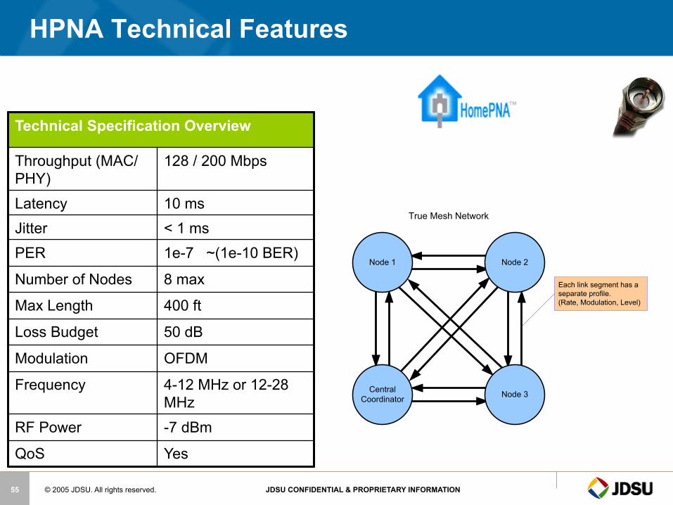
HPNA Technical Features
Node 1 Node 2
Central Coordinator Node 3
True Mesh Network
Each link segment has a separate profile.(Rate, Modulation, Level)
Technical Specification Overview
Throughput (MAC/PHY)
128 / 200 Mbps
Latency 10 ms Jitter < 1 ms PER 1e-7 ~(1e-10 BER)
Number of Nodes 8 max
Max Length 400 ft
Loss Budget 50 dB
Modulation OFDM
Frequency 4-12 MHz or 12-28 MHz
RF Power -7 dBm
QoS Yes
© 2005 JDSU. All rights reserved. JDSU CONFIDENTIAL & PROPRIETARY INFORMATION 56
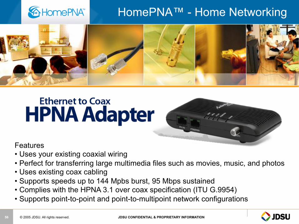
HomePNA™ - Home Networking
Features • Uses your existing coaxial wiring • Perfect for transferring large multimedia files such as movies, music, and photos • Uses existing coax cabling • Supports speeds up to 144 Mpbs burst, 95 Mbps sustained • Complies with the HPNA 3.1 over coax specification (ITU G.9954) • Supports point-to-point and point-to-multipoint network configurations
© 2005 JDSU. All rights reserved. JDSU CONFIDENTIAL & PROPRIETARY INFORMATION 57
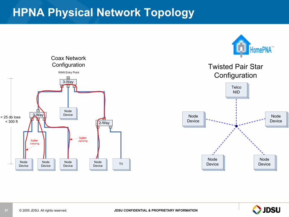
HPNA Physical Network Topology
Node Device
Node Device
TelcoNID
Node Device
Node Device
Twisted Pair Star Configuration
3-Way
2-Way
3-Way
Node Device
Node Device
Node Device TVNode
Device
Node Device
Splitter JumpingSplitter
Jumping
WAN Entry Point
< 25 db loss < 300 ft
Coax Network Configuration
© 2005 JDSU. All rights reserved. JDSU CONFIDENTIAL & PROPRIETARY INFORMATION 58
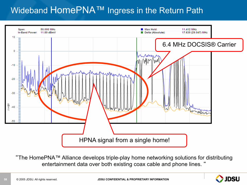
Wideband HomePNA™ Ingress in the Return Path
“The HomePNA™ Alliance develops triple-play home networking solutions for distributing entertainment data over both existing coax cable and phone lines. “
6.4 MHz DOCSIS® Carrier
HPNA signal from a single home!
© 2005 JDSU. All rights reserved. JDSU CONFIDENTIAL & PROPRIETARY INFORMATION 59
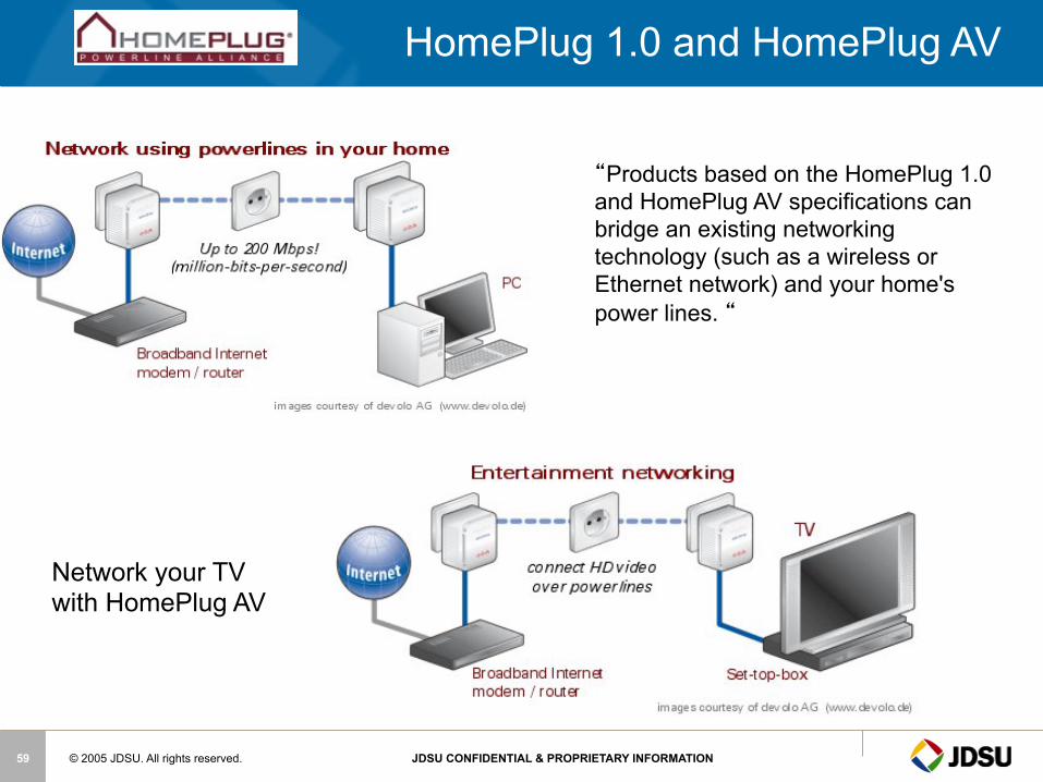
HomePlug 1.0 and HomePlug AV
“Products based on the HomePlug 1.0 and HomePlug AV specifications can bridge an existing networking technology (such as a wireless or Ethernet network) and your home's power lines. “
Network your TV with HomePlug AV

© 2005 JDSU. All rights reserved. JDSU CONFIDENTIAL & PROPRIETARY INFORMATION 60
Node 1 Node 2
Central Coordinator Node 3
True Mesh Network
Each link segment has a separate profile.(Rate, Modulation, Level)
HomePlug AV Technical Features
§ 150 Mbps MAC / 200Mbps Phy – Expected performance of 50-80 Mbps in most installs
§ Works over existing AC power lines § Actively adapts to the wiring § Can support multiple networks on a single media. (with
performance degradation) § True peer-to-peer mesh network § OFDM Modulation § 2-28 MHz § Encrypted data transfer § QoS
© 2005 JDSU. All rights reserved. JDSU CONFIDENTIAL & PROPRIETARY INFORMATION 61
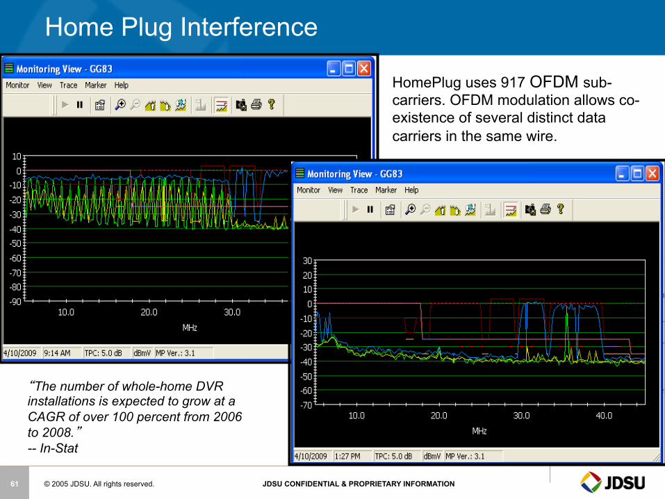
Home Plug Interference
HomePlug uses 917 OFDM sub-carriers. OFDM modulation allows co-existence of several distinct data carriers in the same wire.
“The number of whole-home DVR installations is expected to grow at a CAGR of over 100 percent from 2006 to 2008.” -- In-Stat
© 2005 JDSU. All rights reserved. JDSU CONFIDENTIAL & PROPRIETARY INFORMATION 62
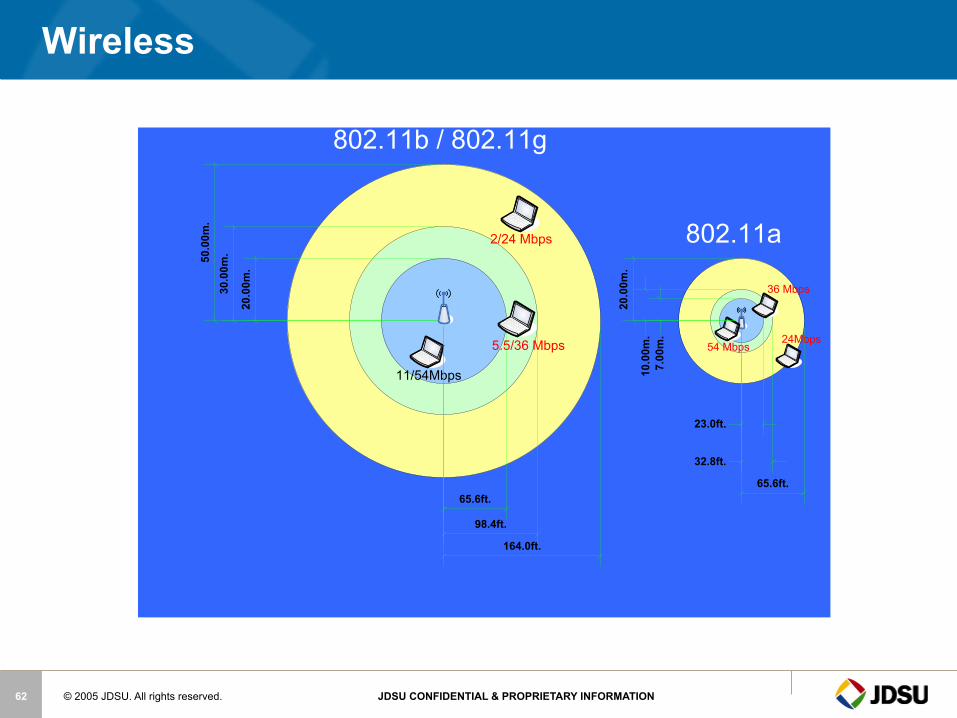
Wireless
20.00m.
30.00m.50.00m.
2/24 Mbps
11/54Mbps
802.11b / 802.11g
54 Mbps
36 Mbps
24Mbps
7.00m.
10.00m.
20.00m.
802.11a
164.0ft.
65.6ft.
98.4ft.
65.6ft.
32.8ft.
23.0ft.
5.5/36 Mbps
© 2005 JDSU. All rights reserved. JDSU CONFIDENTIAL & PROPRIETARY INFORMATION 63
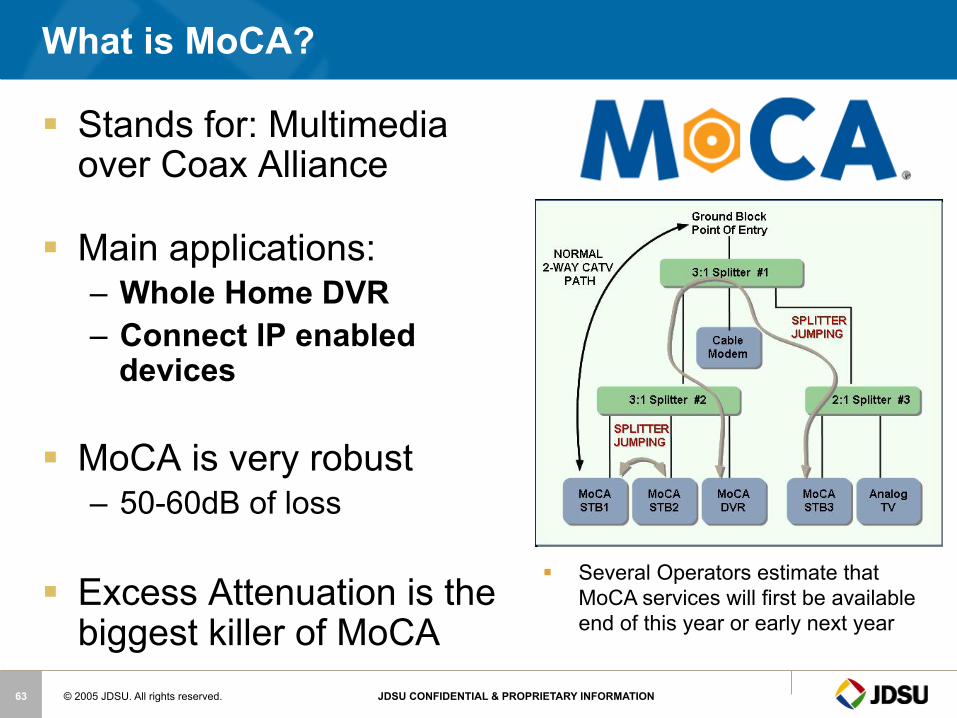
What is MoCA?
§ Stands for: Multimedia over Coax Alliance
§ Main applications: – Whole Home DVR – Connect IP enabled
devices
§ MoCA is very robust – 50-60dB of loss
§ Excess Attenuation is the biggest killer of MoCA
§ Several Operators estimate that MoCA services will first be available end of this year or early next year
© 2005 JDSU. All rights reserved. JDSU CONFIDENTIAL & PROPRIETARY INFORMATION 64
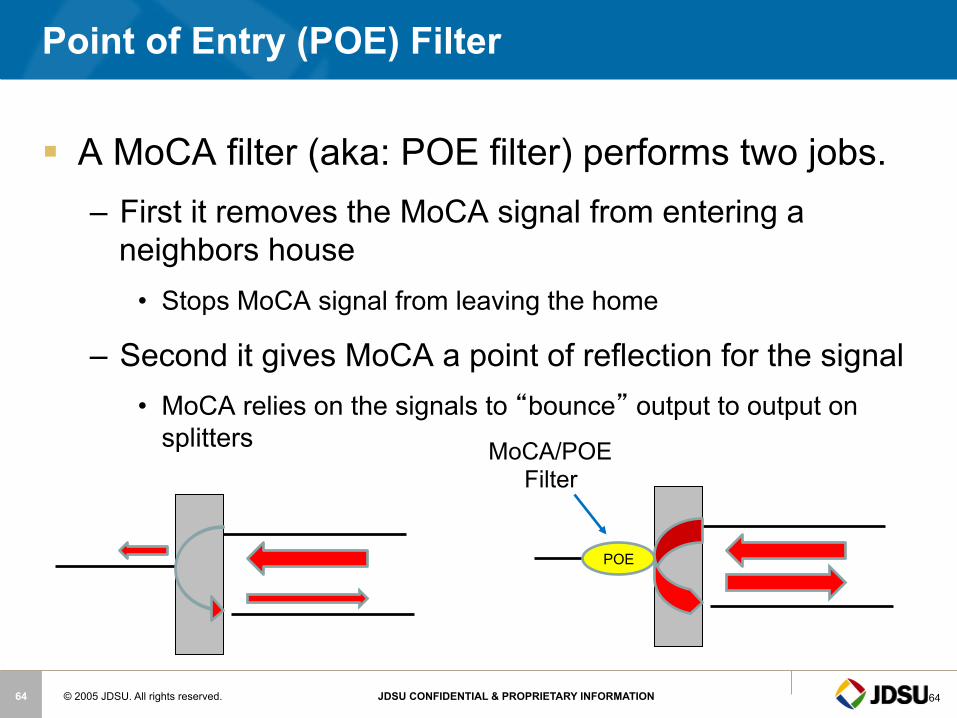
Point of Entry (POE) Filter
§ A MoCA filter (aka: POE filter) performs two jobs. – First it removes the MoCA signal from entering a
neighbors house • Stops MoCA signal from leaving the home
– Second it gives MoCA a point of reflection for the signal • MoCA relies on the signals to “bounce” output to output on
splitters
POE
MoCA/POE Filter
64
© 2005 JDSU. All rights reserved. JDSU CONFIDENTIAL & PROPRIETARY INFORMATION 65
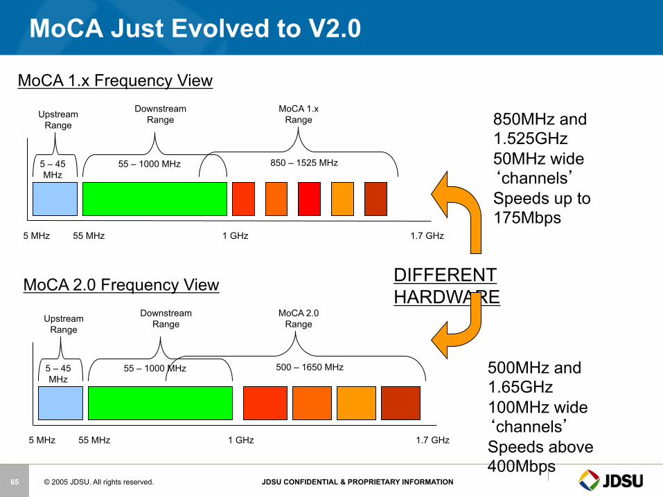
MoCA Just Evolved to V2.0
5 MHz 55 MHz 1 GHz 1.7 GHz
Upstream Range
Downstream Range
MoCA 1.x Range
850 – 1525 MHz 55 – 1000 MHz 5 – 45 MHz
MoCA 1.x Frequency View
5 MHz 55 MHz 1 GHz 1.7 GHz
Upstream Range
Downstream Range
MoCA 2.0 Range
500 – 1650 MHz 55 – 1000 MHz 5 – 45 MHz
MoCA 2.0 Frequency View
850MHz and 1.525GHz 50MHz wide ‘channels’ Speeds up to 175Mbps
500MHz and 1.65GHz 100MHz wide ‘channels’ Speeds above 400Mbps
DIFFERENT HARDWARE

© 2005 JDSU. All rights reserved. JDSU CONFIDENTIAL & PROPRIETARY INFORMATION 66
MoCA 2.0 Detailed
§ MoCA 2.0 (June 15, 2010) - Similar to MoCA 1.1 but with the following differences: – Three new modes of operation:
• Basline Mode: – 400+ Mbps MAC throughput – 700 Mbps PHY Rate – Single 100 MHz Channel
• Enhanced Mode – 800+ Mbps MAC throughput – 1.4 Gbps PHY Rate – Two bonded 100 MHz Channels (“Channel Bonding”)
• “Turbo” mode for a point-to-point configuration that allows: – 500+ Mbps MAC throughput between two connected devices when operating in
Baseline mode – 1+ Gbps MAC throughput when operating in Enhanced mode
– All three modes now have an extended frequency range • 500 MHz through 1650 MHz (center frequencies)
– Backward compatibility with MoCA 1.0 and 1.1 devices • MoCA 2.0 devices can operate at MoCA 2.0 speeds while MoCA 1.x devices are
communicated to at their maximum respectable speeds on the same network
NOTE: MoCA 2.0 is different hardware than previous MoCA 1.1 HW versions
66
© 2005 JDSU. All rights reserved. JDSU CONFIDENTIAL & PROPRIETARY INFORMATION 67
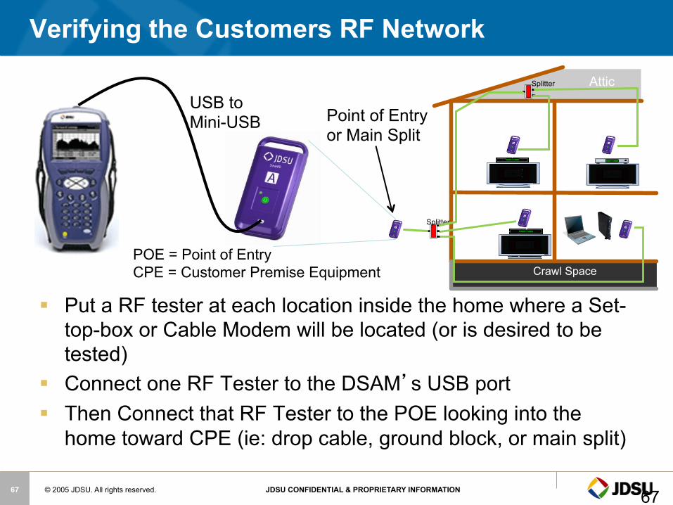
§ Put a RF tester at each location inside the home where a Set-top-box or Cable Modem will be located (or is desired to be tested)
§ Connect one RF Tester to the DSAM’s USB port § Then Connect that RF Tester to the POE looking into the
home toward CPE (ie: drop cable, ground block, or main split)
Verifying the Customers RF Network
USB to Mini-USB Point of Entry
or Main Split
Attic
Crawl Space
Splitter
Splitter
POE = Point of Entry CPE = Customer Premise Equipment
67
© 2005 JDSU. All rights reserved. JDSU CONFIDENTIAL & PROPRIETARY INFORMATION 68
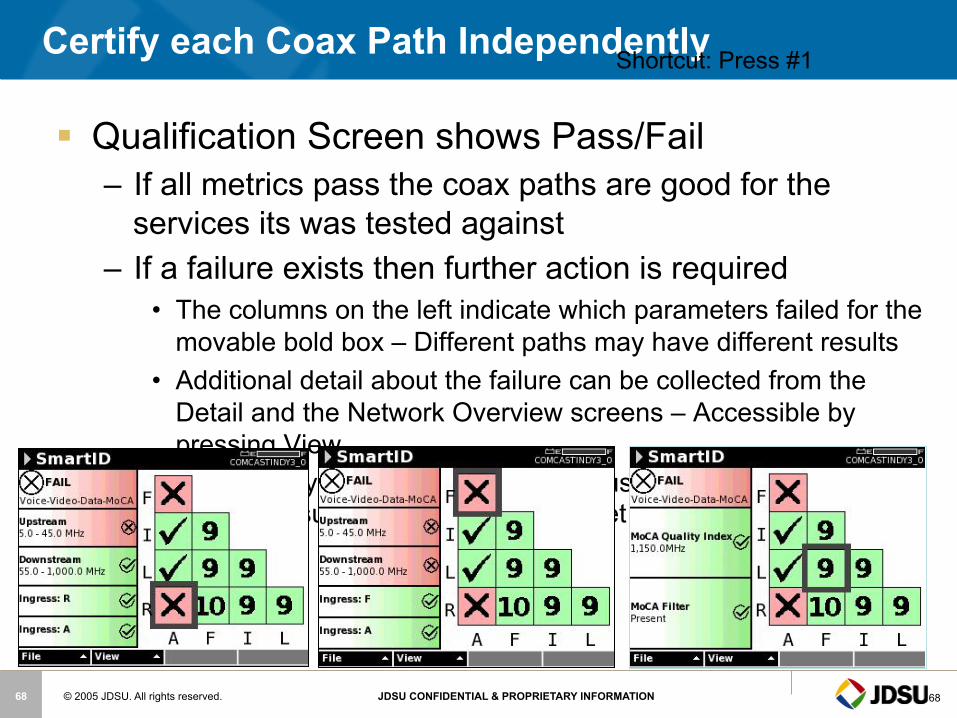
Certify each Coax Path Independently
§ Qualification Screen shows Pass/Fail – If all metrics pass the coax paths are good for the
services its was tested against – If a failure exists then further action is required
• The columns on the left indicate which parameters failed for the movable bold box – Different paths may have different results
• Additional detail about the failure can be collected from the Detail and the Network Overview screens – Accessible by pressing View
• A frequency response graph can be used to help determine why the result was failing the limits set by the test
68
Shortcut: Press #1
© 2005 JDSU. All rights reserved. JDSU CONFIDENTIAL & PROPRIETARY INFORMATION 69
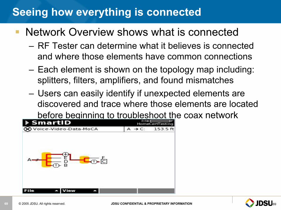
Seeing how everything is connected
§ Network Overview shows what is connected – RF Tester can determine what it believes is connected
and where those elements have common connections – Each element is shown on the topology map including:
splitters, filters, amplifiers, and found mismatches – Users can easily identify if unexpected elements are
discovered and trace where those elements are located before beginning to troubleshoot the coax network
69
© 2005 JDSU. All rights reserved. JDSU CONFIDENTIAL & PROPRIETARY INFORMATION 70
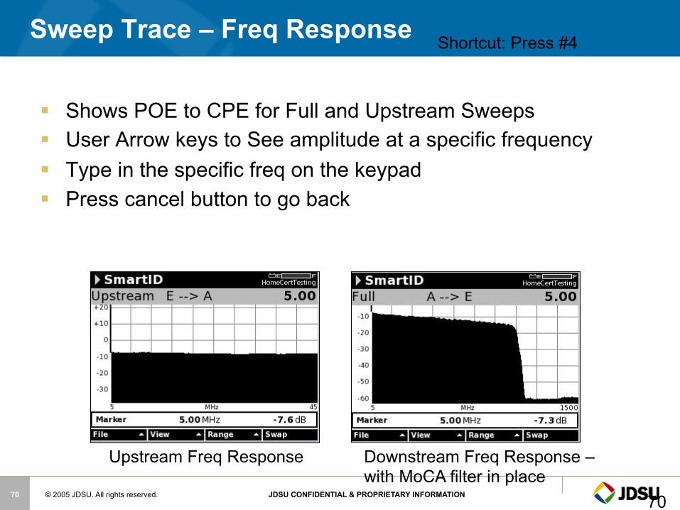
§ Shows POE to CPE for Full and Upstream Sweeps § User Arrow keys to See amplitude at a specific frequency § Type in the specific freq on the keypad § Press cancel button to go back
Sweep Trace – Freq Response
70
Shortcut: Press #4
Upstream Freq Response Downstream Freq Response – with MoCA filter in place
© 2005 JDSU. All rights reserved. JDSU CONFIDENTIAL & PROPRIETARY INFORMATION 71
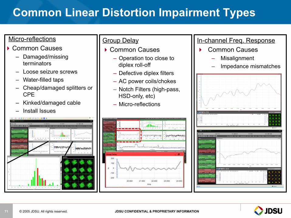
Common Linear Distortion Impairment Types
Micro-reflections Common Causes
– Damaged/missing terminators
– Loose seizure screws – Water-filled taps – Cheap/damaged splitters or
CPE – Kinked/damaged cable – Install Issues
Group Delay Common Causes
– Operation too close to diplex roll-off
– Defective diplex filters – AC power coils/chokes – Notch Filters (high-pass,
HSD-only, etc) – Micro-reflections
In-channel Freq. Response Common Causes
– Misalignment – Impedance mismatches
© 2005 JDSU. All rights reserved. JDSU CONFIDENTIAL & PROPRIETARY INFORMATION 72
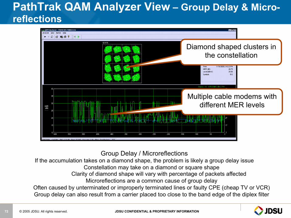
Diamond shaped clusters in the constellation
PathTrak QAM Analyzer View – Group Delay & Micro-reflections
Multiple cable modems with different MER levels
Group Delay / Microreflections If the accumulation takes on a diamond shape, the problem is likely a group delay issue
Constellation may take on a diamond or square shape Clarity of diamond shape will vary with percentage of packets affected
Microreflections are a common cause of group delay Often caused by unterminated or improperly terminated lines or faulty CPE (cheap TV or VCR) Group delay can also result from a carrier placed too close to the band edge of the diplex filter
© 2005 JDSU. All rights reserved. JDSU CONFIDENTIAL & PROPRIETARY INFORMATION 73
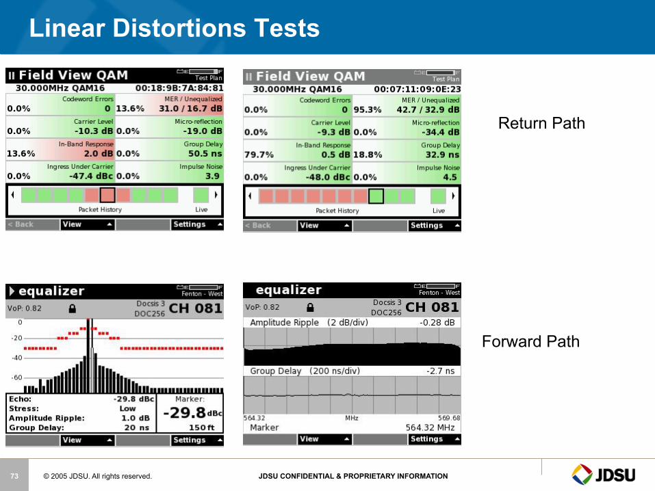
Linear Distortions Tests
Forward Path
Return Path
© 2005 JDSU. All rights reserved. JDSU CONFIDENTIAL & PROPRIETARY INFORMATION 74
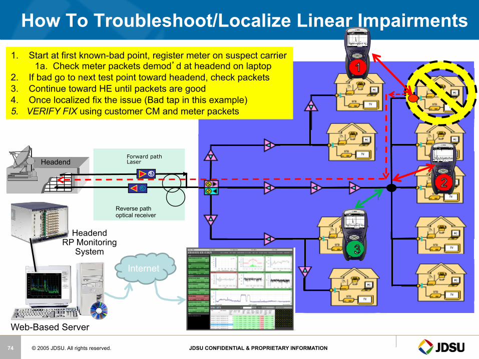
How To Troubleshoot/Localize Linear Impairments
Reverse path optical receiver
Forward path Laser Headend
Web-Based Server
Headend
RP Monitoring System
Internet
1. Start at first known-bad point, register meter on suspect carrier 1a. Check meter packets demod’d at headend on laptop
2. If bad go to next test point toward headend, check packets 3. Continue toward HE until packets are good 4. Once localized fix the issue (Bad tap in this example) 5. VERIFY FIX using customer CM and meter packets
© 2005 JDSU. All rights reserved. JDSU CONFIDENTIAL & PROPRIETARY INFORMATION 75
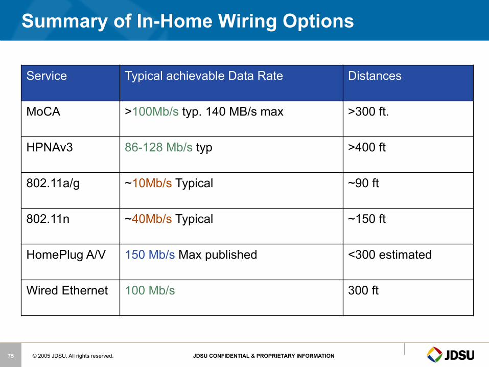
Summary of In-Home Wiring Options
Service Typical achievable Data Rate Distances
MoCA >100Mb/s typ. 140 MB/s max >300 ft.
HPNAv3 86-128 Mb/s typ >400 ft
802.11a/g ~10Mb/s Typical ~90 ft
802.11n ~40Mb/s Typical ~150 ft
HomePlug A/V 150 Mb/s Max published <300 estimated
Wired Ethernet 100 Mb/s 300 ft
© 2005 JDSU. All rights reserved. JDSU CONFIDENTIAL & PROPRIETARY INFORMATION 76
Back to the Basics
§ Check for leakage sources
§ Check for ingress sources
§ Do a visual inspection of cable / connectors / passives
§ Replace questionable cable / connectors / passives
§ Tighten F-connectors per your company’s installation policy – Be very careful not to over tighten connectors on CPE (TVs, VCRs,
converters etc.) and crack or damage input RFI integrity
© 2005 JDSU. All rights reserved. JDSU CONFIDENTIAL & PROPRIETARY INFORMATION 77
Back to the Basics
§ Majority of problems are basic physical layer issues
§ Most of the tests remain the same
§ Check AC power
§ Check forward levels, analog and digital
§ Sweep forward & reverse
© 2005 JDSU. All rights reserved. JDSU CONFIDENTIAL & PROPRIETARY INFORMATION 78
Training… Training… Training…
– You never have too much training! • Learn everything you can about Triple Play & HFC networks
– Company sponsored training – SCTE Chapter Meetings & Certification programs – SCTE EXPO & Emerging Technologies – CED and Communications Technology magazines – Vendor “product specific” training
• Learn everything you can about the devices in your network, both the physical layer and data layer
– Headend: Modulators, Multiplexers, CMTS etc. – Outside plant: Nodes, Amps, Passives etc. – Subscriber’s drop: Digital Converter, DVRs, Cable Modems, eMTAs, house
amps etc. • Learn how to get the most out of your test equipment & CPE diagnostics
– most vendors will train you
– Be thorough - Take pride in your work! • Do the installation right the first time • Take the time to properly certify every drop for Triple Play services
© 2005 JDSU. All rights reserved. JDSU CONFIDENTIAL & PROPRIETARY INFORMATION 79
Questions?
JDSU – See Digital in a Whole New Light!
See digital in a whole new light!
© 2005 JDSU. All rights reserved. JDSU CONFIDENTIAL & PROPRIETARY INFORMATION 80
Thank You ! Mark Ortel
Sales Support Engineer
Cable Networks Division www.jdsu.com
National SCTE Member
Supporter of the National
And Local SCTE Chapters