trus qa workshop - aapm
TRANSCRIPT

TRUS QA Workshop
Introduction
• The goals of using TRUS in prostate brachytherapy• Visualize the prostate
• Need the US to penetrate deeply enough• Need sufficient grey scale resolution to be able to visualize the prostate from background
• Need to be able to accurately measure the volume and linear dimensions of the prostate
• Visualize the needles • Need sufficient resolution to see the needle• Need to be able to see the needle in both AX and SAG
• Visualize the template• Electronic grid must be aligned with both physical grid and TPS grid
• The goal of TRUS QA is to ensure your system can do all of this accurately.
Equipment
• Ultrasound system• TRUS probe• Brachytherapy phantom (e.g. CIRS) (Check that phantom hasn’t changed)• Stepper and stabilizer• Template• Bucket of water (plus adjuncts to bring SOS closer to 1540 m/s)• Needles• Baseline data• Time: ~ 90 minutes
Tests – Element Drop-‐Out
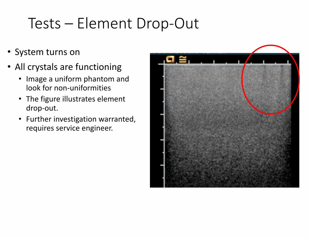
• System turns on• All crystals are functioning• Image a uniform phantom and look for non-‐uniformities
• The figure illustrates element drop-‐out.
• Further investigation warranted, requires service engineer.
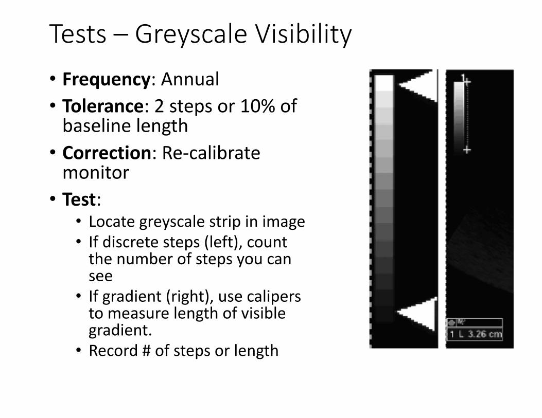
Tests – Greyscale Visibility• Frequency: Annual• Tolerance: 2 steps or 10% of baseline length• Correction: Re-‐calibrate monitor• Test:• Locate greyscale strip in image• If discrete steps (left), count the number of steps you can see• If gradient (right), use calipers to measure length of visible gradient.• Record # of steps or length
Tests – Depth of Penetration
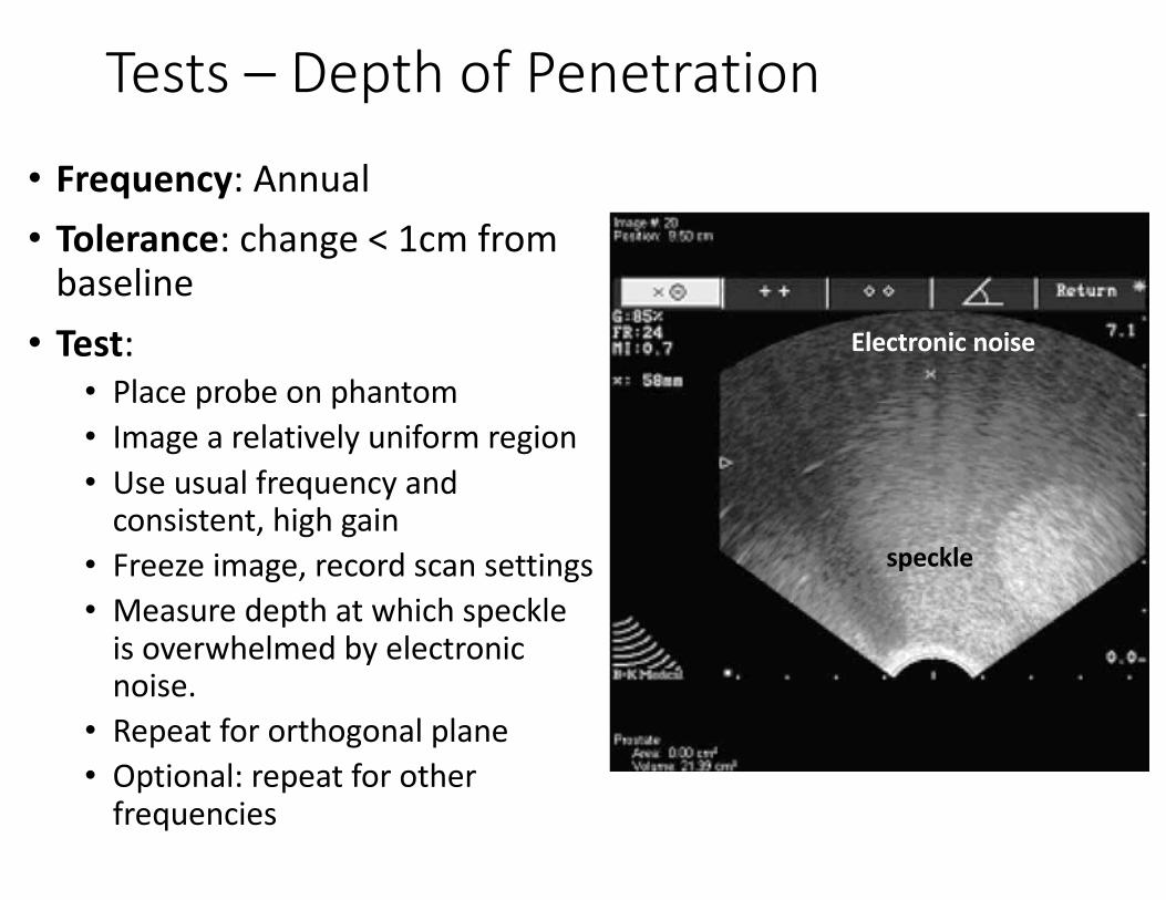
• Frequency: Annual• Tolerance: change < 1cm from baseline • Test:
• Place probe on phantom• Image a relatively uniform region• Use usual frequency and consistent, high gain
• Freeze image, record scan settings• Measure depth at which speckle is overwhelmed by electronic noise.
• Repeat for orthogonal plane• Optional: repeat for other frequencies
speckle
Electronic noise
Tests – Axial and Lateral Resolution
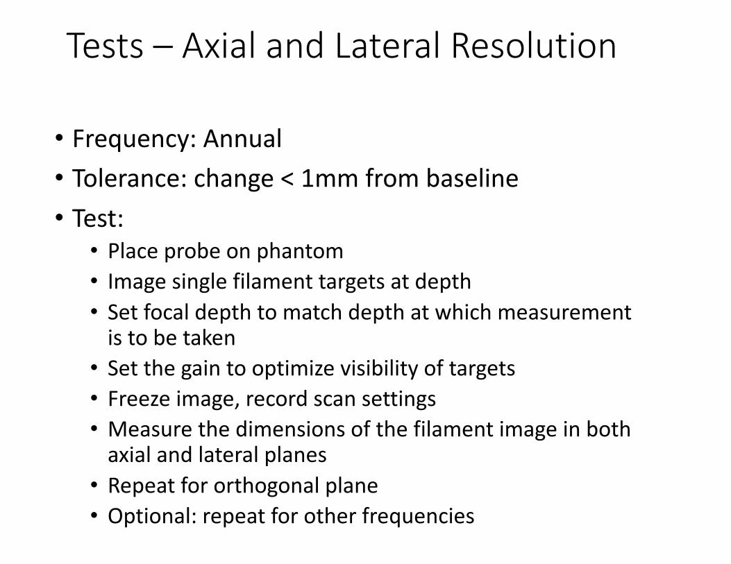
• Frequency: Annual• Tolerance: change < 1mm from baseline • Test:• Place probe on phantom• Image single filament targets at depth• Set focal depth to match depth at which measurement is to be taken
• Set the gain to optimize visibility of targets• Freeze image, record scan settings• Measure the dimensions of the filament image in both axial and lateral planes
• Repeat for orthogonal plane• Optional: repeat for other frequencies
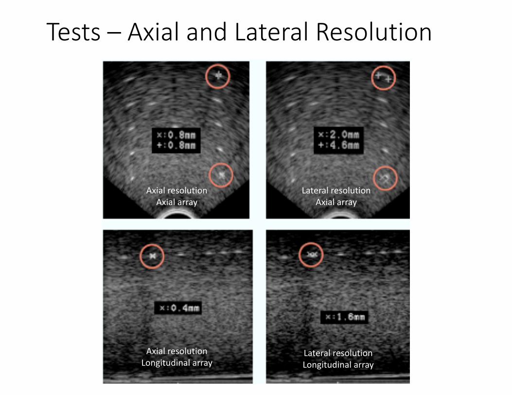
Tests – Axial and Lateral Resolution
Axial resolutionAxial array
Lateral resolutionAxial array
Axial resolutionLongitudinal array
Lateral resolutionLongitudinal array
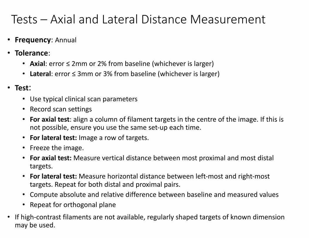
Tests – Axial and Lateral Distance Measurement• Frequency: Annual• Tolerance:
• Axial: error ≤ 2mm or 2% from baseline (whichever is larger)• Lateral: error ≤ 3mm or 3% from baseline (whichever is larger)
• Test:• Use typical clinical scan parameters• Record scan settings• For axial test: align a column of filament targets in the centre of the image. If this is not possible, ensure you use the same set-‐up each time.
• For lateral test: Image a row of targets.• Freeze the image.• For axial test: Measure vertical distance between most proximal and most distal targets.
• For lateral test: Measure horizontal distance between left-‐most and right-‐most targets. Repeat for both distal and proximal pairs.
• Compute absolute and relative difference between baseline and measured values• Repeat for orthogonal plane
• If high-‐contrast filaments are not available, regularly shaped targets of known dimension may be used.
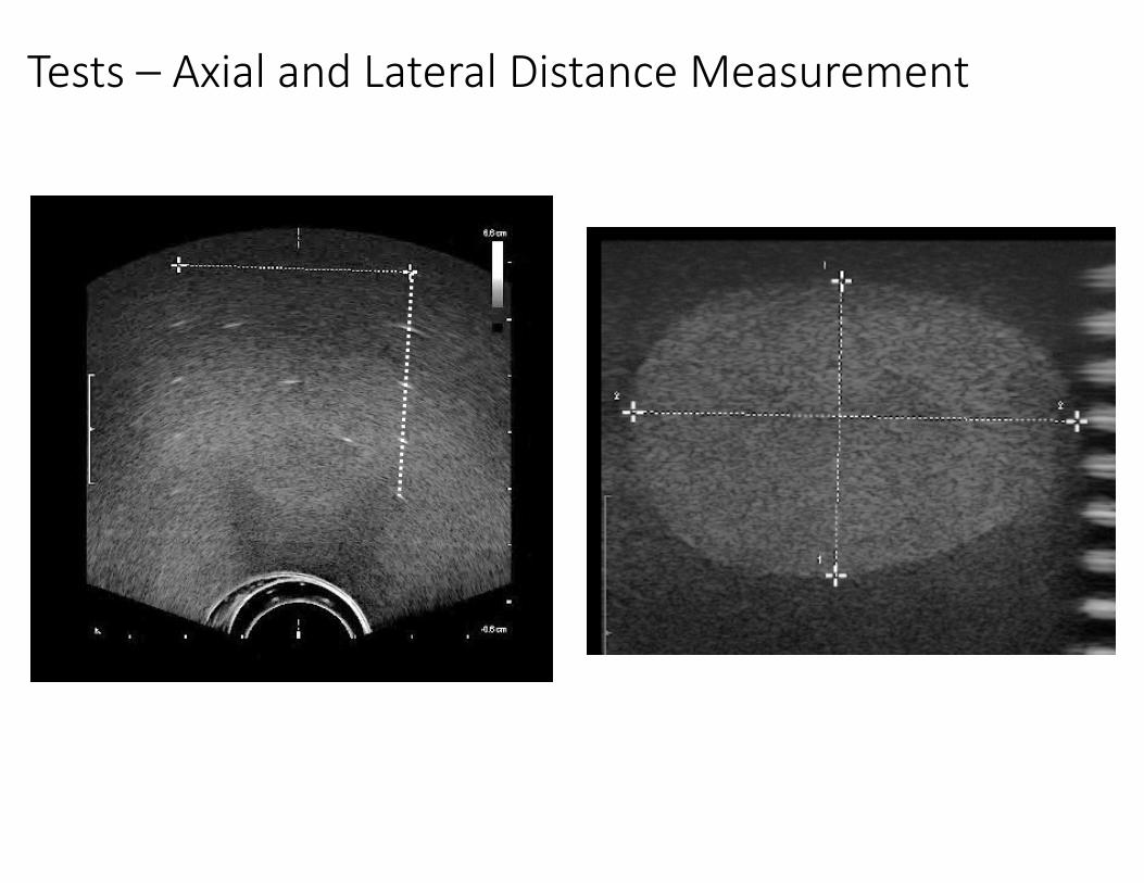
Tests – Axial and Lateral Distance Measurement
Tests – Area and Volume Measurement Accuracy• Frequency: Annual• Tolerance: within 5% of nominal Area or Volume
• Test Area:• Use typical clinical scan parameters• Record scan settings• Scan an object with circular cross section of known size.• Freeze image.• Using appropriate tools on the scanner, trace the boundary of the object.• Record area and calculate % difference.
• Test Volume• Set up the phantom so that the probe can maintain good contact as it is stepped across the volume
• Use typical scan settings• Record scan settings• Scan an egg-‐shaped object in axial cross section.• Locate the equivalent of the base and apex and zero the stepper at the base• Using the typical clinical procedure, translate the probe contouring the target at each step throughout the target
• Record calculated volume and calculate % difference
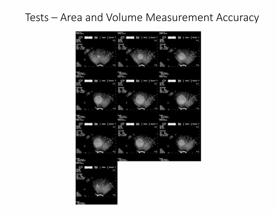
Tests – Area and Volume Measurement Accuracy
Tests – Template/Electronic Grid Alignment
• Frequency: Annual, a vendor’s disposable templates should be checked periodically for consistency
• Tolerance: alignment should be within 3 mm• Test:
• Obtain a water container big enough to immerse the TRUS probe• Ensure water is room temperature and free of bubbles• Set the stepper with probe and needle template attached to be vertical and immerse the probe in the water.
• Place needles at each corner of the template and one in the centre.• Verify that the location of the needle flashes in the image correspond to the physical location of the needles in the template
• Adjust electronic grid as necessary• NOTE: room temperature water has a SOS of 1480 m/s, which will introduce depth dependent distance errors. Adding 43 g of salt per litre of water will increase the SOS to ~1540 m/s. Consider using a probe cover in a saline solution.
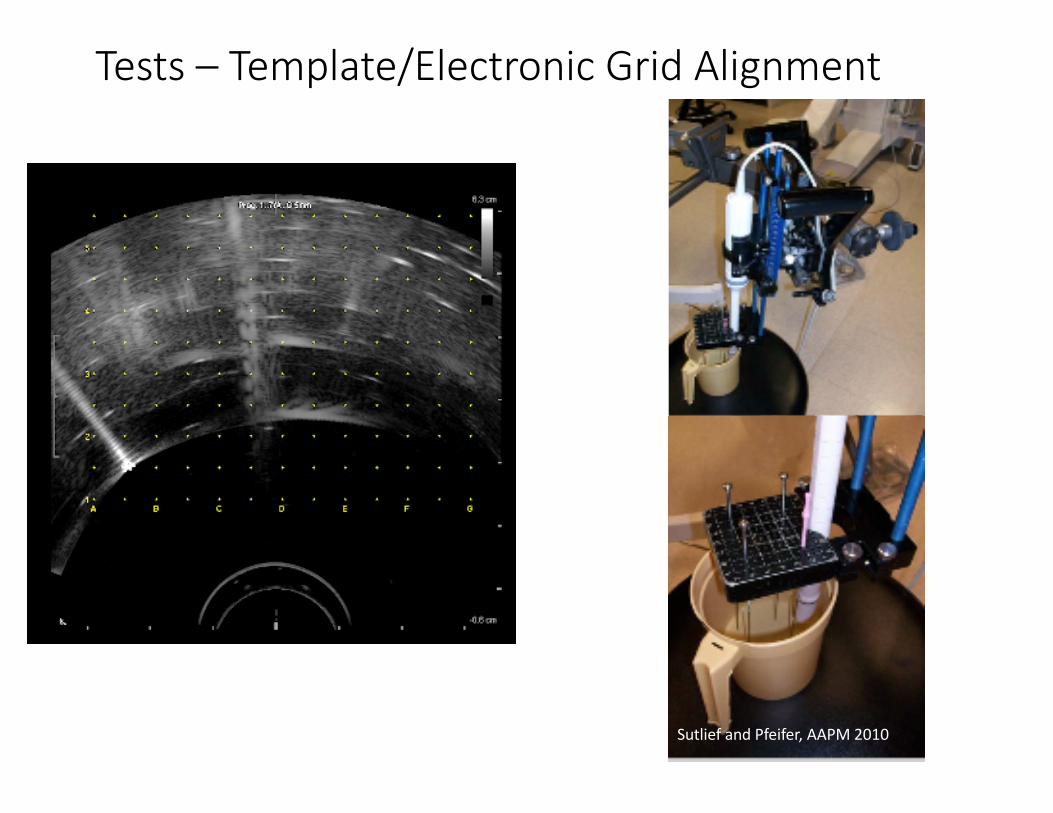
Tests – Template/Electronic Grid Alignment
Sutlief and Pfeifer, AAPM 2010
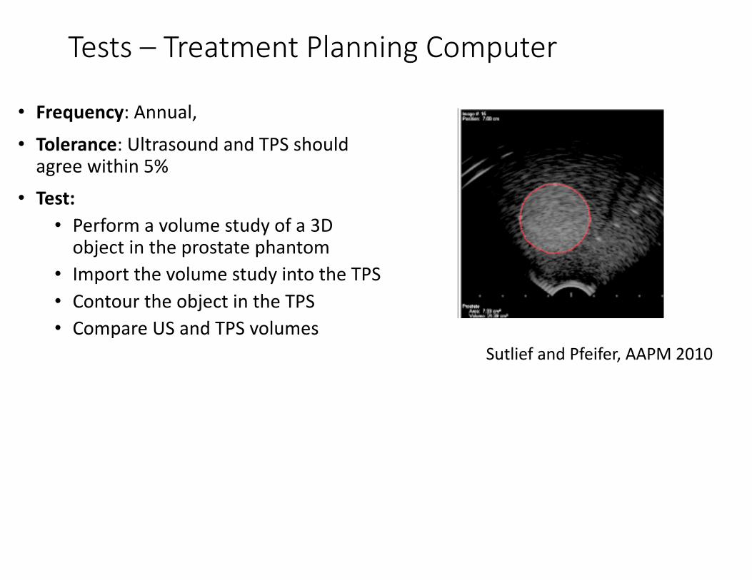
Tests – Treatment Planning Computer
• Frequency: Annual,• Tolerance: Ultrasound and TPS should agree within 5%
• Test:• Perform a volume study of a 3D object in the prostate phantom
• Import the volume study into the TPS• Contour the object in the TPS• Compare US and TPS volumes
Sutlief and Pfeifer, AAPM 2010