truss design
DESCRIPTION
truss designTRANSCRIPT

Timber Design and General Analysis 7-1
Chapter
7Timber Design and
General Analysis
The timber design and general analysis modules can be used to design timber members,calculate section properties, wind pressures on buildings and evaluate drainage systems ofbuilding roofs.

7-2 Timber Design and General Analysis
Quick Reference
General PROKON Analysis Tools....................................................................................... 7-3
Timber Member Design...................................................................................................... 7-5
Section Properties Calculation .......................................................................................... 7-19
Wind Pressure Analysis .................................................................................................... 7-29
Gutter Design ................................................................................................................... 7-35

General PROKON Analysis Tools 7-3
General PROKONAnalysis Tools
The PROKON suite includes a number of simple analysis tools to simplify your life. Theseinclude:
• Timber Member Design: A module that designs timber members for combined axial andbending stresses by post-processing Plane Frame Analysis results
• Section Properties Calculation: For the calculation of bending and torsional properties ofany generalised section.
• Wind Pressure Analysis: For determining the free stream velocity pressure on a building.
• Gutter Design: Use this module to design a drainage system for a roof by sizing a gutter,outlet and downpipe.

7-4 General PROKON Analysis Tools

Timber Member Design 7-5
Timber Member Design
The Timber Member Design module, Timsec is used for designing timber members subjectedto a combination of axial and bending stresses. It acts as a post-processor for the Plane FrameAnalysis module.

7-6 Timber Member Design
Theory and application
A brief background is given below regarding the application of the design principles.
Design scope
The program can design rectangular timber members subjected to axial force and uni-axialbending moment. The output from the Plane Frame Analysis module can be read and memberssizes evaluated and optimised. Members can also be designed interactively without a priorframe analysis.
Design codes
Timsec designs timber uses the allowable stress design procedures given in SABS 0163 - 1980.
Symbols
Where possible, the same symbols are used as in the design codes:
Geometry and design parameters
B : Section width (mm).
D : Section depth (mm).
k2 : Stress modification factor for load sharing.
k3 : Stress modification factor for the type of structure.
k4 : Stress modification factor for quality of fabrication.
k5 : Stress modification factor for moisture content.
Lex factor : Effective length factor for buckling about the x-x axis of the member.
Ley factor : Effective length factor for buckling about the y-y axis of the member.
Le factor : Effective length factor for lateral torsional buckling.L/r : Slenderness ratio of the element, given by the highest ratio of effective length
divided by the radius of gyration, for the x-x and y-y axes.
Note: The program has been developed for fast design of fully triangulated or bracedtrusses. The effective lengths for buckling about the x-x axis and lateral torsional buckling istherefore automatically calculated using the relevant individual member length, i.e. thelength between neighbouring nodes. In contrast with this, the effective length for bucklingabout the y-y axis is based on the laterally unsupported length.

Timber Member Design 7-7
Forces and stresses
F : Axial force (kN).
fc : Axial stress in member (MPa).
fb : Bending stress in member (MPa).
M : Bending moment about the x-x axis (kNm).
pc : Allowable axial stress (MPa).
pb : Allowable bending stress (MPa).
Design parameters
Different design parameters can be set for each group of elements designed:
Effective length factors
The effective length factors depend on the type of restraint to be expected at each end ofcompression members. Guidelines are given in the code:
• Effective lengths for compression members: See clause 6.4.3.
• Effective lateral torsional lengths for members in bending: Refer to clause 6.2.3.2 b.
Considering a truss, the equivalent length Lxx relates to in-plane buckling. For struts whererotational fixety is provided by the connection, e.g. two or more fasteners or a welded connection,a value between 0.70 and 0.85 is usually appropriate. Where rotation at the joints are possible,e.g. single bolted connection, a value of 1.0 would often be acceptable.
The Lyy factor relates to buckling in the vertical plane. This phenomenon can often govern thedesign of the top and bottom flanges of a truss that can buckle in a snakelike 'S' pattern, giving aneffective length equal to unrestrained length. Lateral restraints are normally provided to reducethis effective length. For example, with braced purlins connected to the top flange of the truss, theeffective length could be taken equal to the purlin spacing.
The Le factor relates to lateral torsional buckling about the weak axis. Where a beam has lateralsupports that prevent rotation and lateral movement at its ends and at intermediate points, theeffective laterally unsupported length can be taken as the distance between successive lateralsupports.
Slenderness limits
When launching the program, the slenderness limits defaults to the value given by the designcode, i.e. 180. You may however change the maximum slenderness ratio for each individual loadcase or combination. For example, in the case where wind load is dominant, the maximumslenderness ratio may be increased to 250 (clause 6.4.4).
For tensile forces, the program always uses a maximum allowable slenderness ratio of 250.
7-8 Timber Member Design
Member design
You can use the program to post-process the results of the Plane Frame Analysis module.Alternatively, you can do an independent interactive design of one or more members.
Post-processing frame analysis results
On entering the program, the frame last analysed by the Plane Frame Analysis is loadedautomatically. The frame design procedure can be broken up into the following steps:
• Selecting members to be designed.
• Setting the design parameters.
• Choosing a design approach.
• Selecting load cases and slenderness limits.
• Evaluating the design results.
• Re-analysis of the frame.
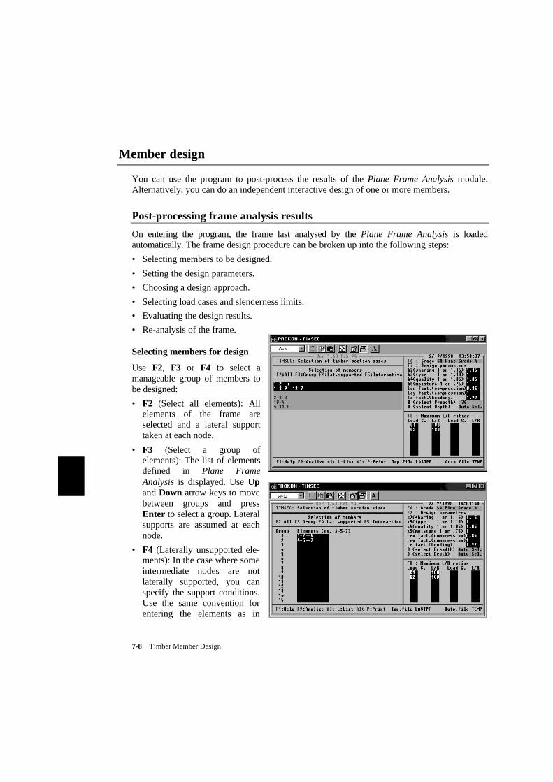
Selecting members for design
Use F2, F3 or F4 to select amanageable group of members tobe designed:
• F2 (Select all elements): Allelements of the frame areselected and a lateral supporttaken at each node.
• F3 (Select a group ofelements): The list of elementsdefined in Plane FrameAnalysis is displayed. Use Upand Down arrow keys to movebetween groups and pressEnter to select a group. Lateralsupports are assumed at eachnode.
• F4 (Laterally unsupported ele-ments): In the case where someintermediate nodes are notlaterally supported, you canspecify the support conditions.Use the same convention forentering the elements as in

Timber Member Design 7-9
Plane Frame Analysis. The first and last nodes entered are taken as supported while theintermediate nodes are assumed to be unsupported. If you enter '1–2– –7', for example, theelement '1–2–3–4–5–6–7' is considered with only nodes 1 and 7 laterally supported.
Note: If you use F4 to indicate nodes with lateral support, Lyy is based on the cumulativelength between supported nodes. However, Lxx and Lvv remain a function of the individualelement lengths between adjacent nodes.
Setting the design parameters
Press F6 to select the grade of timber to design and use F7 to change thedesign parameters as required.
Refer to the clause 5.3 of the code for guidance on values to be used forthe permissible stress modification factors.
After designing a group of members, you can select another group ofmembers and then use a different set of parameters.
Choosing a design approach
Depending on what you would like to achieve, e.g. preliminary sizing or final design checks, youcan choose between the following design approaches:
• Optimising sections: Elements are optimised if you one or both the sectiondimensions, B and D, to 'Auto'.
• Evaluate specific sections: Select values for the section dimensions of youwant to evaluate a specific section size.
Selecting load cases and slenderness limits
When loading the last frame analysis results, the program automatically displays a list of all loadcases and combinations that can be designed and also the default slenderness limit for struts. Youcan manipulate the load case information as follows:
• If you would like to exclude a particular load case or combination from the design, merelydelete the relevant line in the table by pressing D.
Tip: The frame analysis modules allow you to analyse load combination only. The analysisoutput will then be more compact due to the omission of individual load case results.
• You are free to modify the slenderness limit for each individual load case or combination asrequired. In the case where uplift due to wind is dominant, for example, for example, youmay be able to set a higher slenderness limit.
Note: The entered slenderness limits apply to struts only. For elements with tensile forces,the slenderness ratio is automatically limited to 250.

7-10 Timber Member Design
Evaluating the design results
Press F9 to design the selected members. All specified load cases and combinations areconsidered for each member designed. Unless a very large number of elements and load cases areinvolved, the design procedure will normally by completed almost instantaneously.
The following criteria are used in the design:
• The sum of the ratios of the axial and bending stress to the respective allowable stresses maynot exceed unity. In calculating the allowable stress, the program takes account of themember slenderness.
• The slenderness ratio may not exceed the maximum allowable slenderness ratio. Differentlimits are set for compression and tension members.
Press Alt-L to list the design results on the screen. The results of each new design are appendedto the bottom of the existing output.
Tip: To display the results for the last design, press Ctrl-PgDn to jump to the bottom ofthe output.
Re-analysis of the frame
Having evaluated the various member sizes, you may find it necessary to return to the originalframe analysis and make some changes to section sizes. After re-analysing the frame, youshould be in a position to do a final evaluation of the chosen sections.
Tip: In the frame analysis modules it may be easiest to use densities to model theself-weight of members. That way, the self-weight of the frame is updated automaticallywhen changing section sizes.
Interactive design of members
As an alternative to the above procedure, individual members can be designed without the needof a complete frame analysis. You can safely ignore any visible frame analysis output duringinteractive element design.
The design procedure can be broken up into the following steps:
• Setting the design parameters.
• Choosing a design approach.
• Setting a slenderness limit.
• Entering member lengths and forces.
• Evaluating the design results.
Press F5 to enable the interactive design mode.

Timber Member Design 7-11
Setting the design parameters
You may change the design parameters for the group of members, e.g. effective length factors, asrequired. After designing a group of members, you can use a different set of parameters foranother group of members.
Choosing a design approach
Depending on what you would like to achieve, e.g. preliminary sizing or final design checks, youcan choose between the following design approaches:
• Optimising sections: Elements are optimised if you one or both the section dimensions, Band D, to 'Auto'.
• Evaluate specific sections: Select values for the section dimensions of you want to evaluatea specific section size.
Setting a slenderness limit
Press F8 and enter an appropriate maximum allowable slenderness ratio on the first line. If theresults of an earlier frame analysis are displayed, merely edit the slenderness ratio for the firstload case or combination. All other slenderness ratio values will be ignored.
Note: The slenderness limits apply to struts only. For elements with tensile forces, theprogram limits the slenderness ratio to 250.

7-12 Timber Member Design
Entering member lengths and forces
Press F5 to open the interactive member design window. Use as many lines as necessary toenter member lengths, axial forces and bending moments.
Evaluating the design results
The design results are displayed immediately as you enter member data, facilitating interactivemember design. Press F9 to add the displayed results to the output file.
The following criteria are used in the design:
• The total of the ratios of the axial and bending stress to the respective allowable stressesmay not exceed unity.
• The slenderness ratio may not exceed the maximum allowable slenderness ratio.
Press Alt-L to list the design results on the screen. The results of each new interactive designprocedure are appended to the bottom of the output.
Tip: To display the results for the last design, press Ctrl-PgDn to jump to the bottom ofthe output.

Timber Member Design 7-13
Output
The design results are saved in an output file called TEMP. The results of each consecutivedesign are appended to the end of the output.
Note: On exiting and re-entering the program, the design output is cleared automatically.
Viewing output
Press Alt-L to view the output file in the PROKON Text Editor. You can page through theoutput tables, delete unwanted information and even add your own comments. Press Esc to exitthe editor. Refer to Chapter 2 for detail on using the editor functions.
Tip: Design results are always appended to the bottom of the output file. To display theresults for the last design, press Ctrl-PgDn to jump to the bottom of the output.
Printing output
Press Alt-P to print the design output file. In the Print Manager, you can press F5 to view oredit the output file before printing.
7-14 Timber Member Design
Customising
You can edit the default section sizes and add new grades of timber by editing the Timsecconfiguration file. The configuration is saved in the PROKON program directory in a filecalled TIMSEC.CFG. Use any text editor to edit the grades and sections tables:
Adding a new grade of timber
Up to twenty timber grades can be defined. To add a new grade by entering its name andproperties in a new row of the first table:
• Using the PROKON Text Editor, you can position the cursor on the last line, i.e. 'Stocklam'and the press Alt-L to mark the line.
• Press Alt-C to copy the line and Alt-U to remove the highlight.
• Finally replace the information on the new line with the appropriate values.
• In the Sizes column, enter the section range number defined in the next table.
��������������������������������������������������������������������������GRADE � Bending � Tension �Compression� E-modulus �Sizes���������������������������������������������������������������������������SA Pine Grade 4 � 4.0 � 2.2 � 6.4 � 6000 � 1 ��SA Pine Grade 5 � 5.2 � 3.0 � 7.4 � 7800 � 1 ��SA Pine Grade 6 � 6.0 � 3.6 � 8.5 � 8500 � 1 ��SA Pine Grade 7 � 7.1 � 4.5 � 9.4 � 9600 � 1 ��SA Pine Grade 8 � 8.0 � 4.8 � 9.9 � 10500 � 1 ��SA Pine Grade 10 � 10.5 � 6.0 � 10.8 � 12000 � 1 ��SA Pine Grade 12 � 12.4 � 7.4 � 12.7 � 14250 � 1 ��SA Pine Grade 14 � 14.6 � 8.6 � 14.2 � 16000 � 1 ��SA Pine D2/A Lam � 6.5 � 4.2 � 9.0 � 8000 � 2 ��SA Pine D2/A1 Lam� 8.1 � 5.7 � 10.0 � 9000 � 2 ��SA Pine D1/A Lam � 8.1 � 5.7 � 10.0 � 9000 � 2 ��SA Pine D1/A1 Lam� 10.1 � 7.5 � 11.0 � 10000 � 2 ��Saligna Lam � 9.9 � 7.4 � 12.4 � 13100 � 3 ��Stocklam � 6.0 � 3.0 � 8.0 � 7500 � 2 ��New Timber Grade � 12.0 � 7.0 � 12.0 � 15000 � 4 ��������������������������������������������������������������������������
Adding a new grade of timber
By default, the sections listed for the first three size ranges are based on the nominalrough-sawn dimension given on Appendix C of SABS 0163 - 1980. You may change thesesizes as required and also add a fourth range of sizes. A maximum of fifty sections per rangecan be entered.
To enter new section sizes:
• Using the PROKON Text Editor, you can ensure that blank spaces are overwritten withoutthe table lines being moved. Press Ins to toggle between insert and overwrite mode.

Timber Member Design 7-15
• If more rows are required in the table, copy an existing row as many times as required usingAlt-L and Alt-C.
• Enter the section dimensions for the relevant range.
��������������������������������������������������Standard Sizes (mm) ��������������������������������������������������� 1 � 2 � 3 � 4 �� B x D � B x D � B x D � B x D ��������������������������������������������������� 36 x 36 � 40 x 195 � 38 x 99 � 50 x 50 �� 36 x 48 � 40 x 228 � 38 x 152 � 50 x 100 �� 36 x 73 � 65 x 195 � 38 x 198 � 50 x 150 �� 36 x 111 � 65 x 228 � 38 x 231 � 100 x 100 �� 36 x 149 � 65 x 261 � 45 x 99 � 100 x 150 �� 36 x 225 � 65 x 295 � 45 x 152 � 150 x 150 �� 48 x 48 � 65 x 328 � 45 x 198 � �� 48 x 73 � 65 x 361 � 45 x 231 � �� 48 x 111 � 65 x 395 � 45 x 297 � �� 48 x 149 � 95 x 261 � 70 x 152 � �� 48 x 225 � 95 x 295 � 70 x 198 � �� 73 x 73 � 95 x 328 � 70 x 231 � �� 73 x 111 � 95 x 361 � 70 x 264 � �� 73 x 149 � 95 x 395 � 70 x 297 � �� 73 x 225 � 95 x 428 � 70 x 396 � �� � 95 x 461 � 102 x 198 � �� � 95 x 495 � 102 x 297 � �� � 135 x 295 � 102 x 396 � �� � 135 x 328 � 102 x 495 � �� � 135 x 361 � 127 x 297 � �� � 135 x 395 � 127 x 396 � �� � 135 x 428 � 127 x 495 � �� � 135 x 461 � 127 x 594 � �� � 135 x 495 � 142 x 297 � �� � 135 x 528 � 142 x 396 � �� � 135 x 561 � 142 x 495 � �� � 135 x 595 � 142 x 594 � ��������������������������������������������������

7-16 Timber Member Design
Example
In the preceding text, images are shown pertaining to the design of a timber truss. A sampleanalysis input and design output file is given below:
TITLE: Timber Truss Example
NODES Unit: m�������������������������������������������������������������������No �X �Y �No-of�Inc �X-inc �Y-inc ��������������������������������������������������������������������1 �0 �0 �7 �1 �1.0 � ��8 �1.0 �0.3 �1 �1 �1.0 �0.3 ��10 �3.0 �0.9 �2 �1 �1.0 �-0.3 �������������������������������������������������������������������ELEMENTS�����������������������������������������������������������������������������Element Definition �SecNo�Fcode�No-of�Inc ������������������������������������������������������������������������������1-2--7 �1 � � � ��1-8-9--12-7 �1 � � � �� � � � � ��2-8-3 �2 �11 �1 �1 ��10-4 �2 �11 � � ��4-11-5 �2 �11 �1 �1 �����������������������������������������������������������������������������SUPPORTS Prescr.Displacements(m) Spring Constants(kN/m)��������������������������������������������������������������������������No �XYR �X-Disp �Y-Disp �R-Disp �X-sprng�Y-sprng�R-sprng�No-of�Inc ���������������������������������������������������������������������������1 �XY � � � � � � � � ��7 �Y � � � � � � � � ��������������������������������������������������������������������������SECTION PROPERTIES (kN/m3)�����������������������������������������������������������������������������No �Designation �A(m2) �I(m4) �E(kPa) �Density �ëT(øC) �Exp.Coef������������������������������������������������������������������������������1 �36x225 �8.10E-3 �34.2E-6 �10.5E6 �6.5 � � ��2 �36x36 �1.30E-3 �0.14E-6 �10.5E6 �6.5 � � �����������������������������������������������������������������������������NODAL LOADS��������������������������������������������������������������L C �Node �Px(kN) �Py(kN) �M(kNm) �No-of�Inc ���������������������������������������������������������������1 �8 � �-0.3 � �4 �1 ��2 �8 � �-1.5 � �4 �1 ��3 �8 � �1.2 � �4 �1 ��������������������������������������������������������������ELEMENT LOADS Unit: kN/m�����������������������������������������������������������������������������L C �Element Definition �Direc�W-begin �W-end �No-of�Inc ������������������������������������������������������������������������������ � � � � � � �����������������������������������������������������������������������������
Timber Member Design 7-17
LOAD COMBINATIONS�����������������������������������������No �Load Case �ULS Factor�SLS Factor������������������������������������������C1 �1 �1.0 �1.0 �� �2 �1.0 �1.0 �� � � � ��C2 �1 �0.7 �1.0 �� �3 �1.0 �1.0 �����������������������������������������OPTIONS���������������������������������������Second order analysis N ��Analyse load combinations only Y ���������������������������������������
Design output:
INPUT FILE: Timber Truss ExampleDesign Code: SABS 0163 - 1980
Comment: Initial check of main members for 36x225.óóóóóóóóóóóóóóóóóóóóóóóóóóóóóóóóóóóóóóóóóóóóóóóóóóóóóóóóóóóóóóóóóóóóóóóóóóóóDesign parameters: Grade=SA Pine Grade 4 k2=1.15 k3=1 k4=1.05 k5=1 Lex=0.85 Ley=1 Le=1.92 B= 36 D=225Load cases considered: 1 2Maximum L/R ratios : 180 180Element Length L.C. F(kN) M(kNm) L/R Section fc/pc fb/pb Total���������������������������������������������������������������������������� 1- 2 1.000 C1 -11.64 0.68 96 36x225 0.54 0.50 1.04 2- 3 1.000 C1 -11.64 0.68 96 36x225 0.54 0.50 1.04 � � � � � � � � � 11- 12 1.044 C1 12.10 0.63 100 36x225 0.61 0.46 1.08 7- 12 1.044 C1 12.34 0.63 100 36x225 0.63 0.46 1.09����������������������������������������������������������������������������
Comment: Second check of main for 48x225.óóóóóóóóóóóóóóóóóóóóóóóóóóóóóóóóóóóóóóóóóóóóóóóóóóóóóóóóóóóóóóóóóóóóóóóóóóóóDesign parameters: Grade=SA Pine Grade 4 k2=1.15 k3=1 k4=1.05 k5=1 Lex=0.85 Ley=1 Le=1.92 B= 48 D=Auto Sel.Load cases considered: 1 2Maximum L/R ratios : 180 180Element Length L.C. F(kN) M(kNm) L/R Section fc/pc fb/pb Total���������������������������������������������������������������������������� 1- 2 1.000 C1 -11.64 0.68 72 48x225 0.41 0.36 0.76 2- 3 1.000 C1 -11.64 0.68 72 48x225 0.41 0.36 0.76 � � � � � � � � � 11- 12 1.044 C1 12.10 0.63 75 48x225 0.28 0.33 0.61 7- 12 1.044 C1 12.34 0.63 75 48x225 0.28 0.33 0.61����������������������������������������������������������������������������

7-18 Timber Member Design
Comment: Check of bottom chords with lateral supports at middle only.óóóóóóóóóóóóóóóóóóóóóóóóóóóóóóóóóóóóóóóóóóóóóóóóóóóóóóóóóóóóóóóóóóóóóóóóóóóóLaterally supported elementsDesign parameters: Grade=SA Pine Grade 4 k2=1.15 k3=1 k4=1.05 k5=1 Lex=0.85 Ley=1 Le=1.92 B=Auto Sel. D=Auto Sel.Load cases considered: 1 2Maximum L/R ratios : 180 180Element Length L.C. F(kN) M(kNm) L/R Section fc/pc fb/pbTotal���������������������������������������������������������������������������� 1- 2 1.000 C1 -11.64 0.68 216 48x225 0.41 0.36 0.76 2- 3 1.000 C1 -11.64 0.68 216 48x225 0.41 0.36 0.76 3- 4 1.000 C2 5.47 0.14 142 73x111 0.54 0.19 0.73
4- 5 1.000 C2 5.47 0.14 142 73x111 0.54 0.19 0.73 5- 6 1.000 C1 -11.64 0.68 216 48x225 0.41 0.36 0.76 6- 7 1.000 C1 -11.64 0.68 216 48x225 0.41 0.36 0.76����������������������������������������������������������������������������
Comment: Interactive design on secondary members.óóóóóóóóóóóóóóóóóóóóóóóóóóóóóóóóóóóóóóóóóóóóóóóóóóóóóóóóóóóóóóóóóóóóóóóóóóóóDesign parameters: Grade=SA Pine Grade 4 k2=1.15 k3=1 k4=1.05 k5=1 Lex=0.85 Ley=1 Le=1.92 B=Auto Sel. D=Auto Sel.Load cases considered: 1 2Maximum L/R ratios : 180 180Element Length L.C. F(kN) M(kNm) L/R Section fc/pc fb/pb Total���������������������������������������������������������������������������� 0.52 1.22 0.23 50 36x111 0.05 0.64 0.69 0.52 0.98 0.65 38 48x149 0.02 0.76 0.78 0.52 1.67 0.22 50 36x111 0.06 0.62 0.68 0.75 2.01 0.22 72 36x111 0.12 0.62 0.74 0.75 2.46 0.32 54 48x111 0.07 0.67 0.75

Section Properties Calculation 7-19
Section Properties Calculation
The Section Properties Calculation module, Prosec, is used to calculate the bending andtorsional properties of any arbitrary section. The section can be solid or have openings.

7-20 Section Properties Calculation
Theory and application
An overview is given below regarding the theories used to calculate section properties.
Scope
Prosec can be used to calculate the properties of any arbitrary section. The section can be solidor have openings. For bending property calculation, the program uses a simple technique ofdivision into sub-sections. The Prandtl membrane analogy is used to determine the torsionalsection properties, including the shear centre, St. Venant torsional constant and torsionalwarping constant.
Sign convention
A simple Cartesian sign convention applies:
• X coordinates are taken positive to the right and negative to the left.
• Y coordinates are taken positive upward and negative downward.
List of symbols
Below is a list of symbols used for the bending and torsional section properties:
Bending properties
A : Area of the cross section.
Ixx, Iyy : Second moment of inertia about X and Y-axis.
Ixy : Deviation moment of inertia.
Iuu, Ivv : Second moment of inertia about major axis and minor axis.
Ang : Anti-clockwise angle from the X-axis to the U-axis.
Zxx : Elastic section modulus in relation to the top or bottom edge.
Zyy : Elastic section modulus in relation to the left or right edge.
Zuu : Minimum section modulus in relation to the U-axis.
Zvv : Minimum section modulus in relation to the V-axis.
Zplx, Zply : Plastic modulus about X and Y-axis.
Xc : Horizontal centroid position measured from the leftmost extremity of thesection.

Section Properties Calculation 7-21
Yc : Vertical centroid position measured from the bottom most extremity of thesection.
rx, ry : Radius of gyration about the X or Y-axis.
ru, rv : Radius of gyration about the U or V-axis.
Xpl : Horizontal distance from leftmost extremity to centre of mass.
Ypl : Horizontal distance from topmost extremity to centre of mass.
Torsional properties
τ : Shear stress.
X : Horizontal position of shear centre from the leftmost extremity of the section.
Y : Vertical position of shear centre from the bottom of the section.
J : St. Venant torsional constant.
Zt : Torsional modules.
Cw : Warping torsional constant.
Units of measurement
All input and output values are used without a unit of measurement. Whether you define asection using sizes for millimetres, metres, inches or feet, the output will effectively be given inthe same unit of measurement.

7-22 Section Properties Calculation
Input
A section is defined by entering one or more shapes in the input table. A shape may comprisestraight lines and arcs or may be a circle. When more than one shape is entered, the shapes willaccumulate and form one section. You can create openings by entering negative shapes that aresubtracted from the section.
Note: If preferred, section input can be done graphically. Use Padds to draw a polygon toscale or import a DXF drawing from another CAD system. Then generate an input filefor Prosec.
Entering a section
The Code column is used for categorise the data that follows in the next columns:
'+' : The start of a new polygon or circle. An absolute reference coordinate must beentered in the X/Radius and Y/Angle columns.
'–' : Start of an opening. An absolute reference coordinate must be entered in theX/Radius and Y/Angle columns.
'R' : Indicates a line drawn with relative coordinates.
'L' : Indicates a line drawn with absolute coordinates.
'A' : An arc that continues from the last line or arc. The arc radius and angle areentered in the X/Radius and Y/Angle columns respectively. The angle ismeasured clockwise from the previous line or arc end point.
'C' : A circle with the radius entered in the X/Radius column.
Note: If the Code column is left blank, relative coordinates are used.
The X/Radius and Y/Angle columns are used for entering coordinates, radii and angles:
X : Absolute or relative X coordinate. Values are taken positive to the right andnegative to the left.
Radius : Radius of a circle or an arc.
Y : Absolute or relative Y coordinate. Values are taken positive upward andnegative downward.
Angle : Angle than an arc is extending through.
Note: If the X/Radius or Y/Angle column is left blank, a zero value is used.

Section Properties Calculation 7-23
Entering a shape
A shape has two basic components:
• A reference coordinate which gives the starting point of a polygon or the centre of a circle.
• One or more entries defining the polygon’s coordinates of lines and arcs or a circle’s radius.
After entering each coordinate, the image of the polygon updated.
Note: The starting point of a polygon is also used as the ending point and the polygon isclosed automatically. It is therefore not necessary to re-enter the starting coordinate to closea polygon.
The reference coordinate
Every polygon has a start point and every circle has a centre point. These points are calledreference points and are entered as absolute coordinates:
• In the Code column, enter either a '+' or '–' to indicate the start of a new shape. Entering a '+'means that the shape will be added to the section. Likewise, a '–' means that the shape willbe subtracted, e.g. an opening.
• Enter the absolute values of the reference coordinate in the X/Radius and Y/Angle columns.
Coordinates defining the polygon
Given a reference coordinate, two or more additional coordinates are required to define theshape of a polygon. In the case of a circle, only a reference coordinate and radius is required.A coordinate may be entered using absolute or relative values:
• If the Code column is left blank, the coordinate is taken relative from the last point entered.
• An absolute coordinate is entered by setting the Code to 'L'.
• The coordinate values are entered in the X/Radius and Y/Angle columns. A negative X orY coordinate must be preceded by a minus sign. The plus sign before a positive X or Ycoordinate is optional.
• A circular arc is defined by setting the Code to 'A' and entering the radius in the X/Radiuscolumn. The arc is then taken to extend from the end point of the last line or arc, starting atthe angle that the previous line or arc ended and extending through the angle specified in theY/Angle column.
• Define a circle by setting the Code to 'C' and entering the coordinate for the centre point. Onthe next line, enter the radius in the X/Radius column.
Note: You can rotate the section by pressing F6.

7-24 Section Properties Calculation
Procedures for entering shapes
Step-by-step procedures for entering typical section Codes are given below:
Entering a polygon comprising straight lines
A polygon is defined by entering a start point followed by a few lines of additional coordinates.The polygon can be defined using relative or absolute coordinates or both.
Using relative coordinates:
• Define the start position of the polygon by setting the Code to + and entering the absolutecoordinate in the X/Radius and Y/Angle columns.
• Next, leaving the Code column blank, enter the consecutive corner points of the polygon inthe X/Radius and Y/Angle columns. By leaving the Code column blank, the enteredcoordinates are set to relative coordinates.
Using absolute coordinates:
• Define the start position of the polygon by setting the Code to + and entering the absolutecoordinate in the X/Radius and Y/Angle columns.
• For each following coordinate, enter an L in the Code column and enter the absolutecoordinate values in the X/Radius and Y/Angle columns.
Entering a polygon comprising lines and arcs
A polygon with one or more arcs is defined in a similar way as a normal polygon:
• Define the start position of the polygon by setting the Code to + and entering the absolutecoordinate in the X/Radius and Y/Angle columns.
• Define straight lines by entering the consecutive corner points using relative or absolutecoordinates.
• For an arc, set the Code to A and enter its radius and angle in the X/Radius and Y/Anglecolumns. The arc will be taken to extend from the previous line/arc through the specifiedangle. A positive angle is taken as a clockwise rotation and a negative angle as an anti-clockwise rotation.
Tip: If an arc is to start at a certain angle, simply precede it with a short line at that angle.
Entering a circle
A circle is defined by entering the centre point followed by its radius in the next line:
• Define the centre point of the circle by setting the Code to + and entering the absolute X andY coordinates. If you leave either of the coordinates blank, a value of zero is used.
• On the next line, set the Code to C and enter the radius of the circle in the X/Radiuscolumn.

Section Properties Calculation 7-25
Note: A circle should be considered as a complete shape. If a circle has to be incorporatedin another shape, a polygon with arcs should be used.
Entering an opening
An opening is defined exactly like any other shape, with the exception that it is entered as anegative shape:
• Define the start position of the polygon by setting the Code to – and entering the absolutecoordinate in the X/Radius and Y/Angle columns.
• Define lines, arcs or a circle by entering the relevant points as described in the examplesabove.

7-26 Section Properties Calculation
Analysis
Two separate analysis procedures are used to calculate the bending and torsional sectionproperties. The bending analysis is completed almost instantaneously. However, the torsionalanalysis procedure uses a sophisticated finite difference analysis technique and therefore takeslonger to complete.
Analysis settings
Press F8 to adjust the analysis settings applicable to the torsional analysis:
• Poisson ratio: This value influences the shearstress distributions during torsional analysis. Ittherefore also has an effect on the position of theshear centre and warping torsion constant.Typical values given in the table alongside.
• Number of equations: For determination of thetorsional section properties, the finite differencemesh is sized to yield approximately the specifiednumber of equations. More equations will takelonger to solve, but may yield better accuracy,especially when analysing thin-walled sections.
Calculating bending section properties
Press F4 to calculate the section's bending properties. The section properties are calculatedusing a simple method of division into sub-sections:
• Circles and arcs are firstconverted to polygons withapproximately the sameshapes. The program useslines at 30° angle incrementsfor this purpose.
• The section is then sub-divided into a series oftrapeziums and the propertiesare calculated for eachtrapezium.
• The global section propertiesare finally calculated throughsummation of the valuesobtained for each trapezium.
Material Poisson ratio
Aluminium 0.16
Concrete 0.20
Steel 0.30

Section Properties Calculation 7-27
Calculating torsional section properties
To calculate the torsional section properties, press F5. A sophisticated finite different analysismethod is used for calculating the torsional section properties.
The Prandtl membrane analogy is used for determining the Y and X shear stresses and J, theSt. Venant torsional constant. The membrane is modelled using a finite difference mesh.
The shear stress distributions inthe Y and X directions aredetermined for a unit loadapplied in the Y direction. Theshear centre is then calculated byconsidering the moment of shearstresses about the centre of mass.
The torsional constant, J, is takenas twice the volume below themembrane. The maximum slopeof the membrane then gives thetorsional modulus. Themaximum torsional shear stresscan be obtained by dividing thetorsional moment with thetorsional modulus Zt.
Warping torsion is evaluated by using the relationship between shear and axial deformationfrom classical elastic theory. The shear deformation is obtained from the pure torsion analysis.The warping constant, Cw, is then determined from the longitudinal displacements.
Note: Press Prtsc to send a screen image to the printer. When using the program throughthe Windows version of PROKON, pressing Prtsc will send the screen image toCalcpad instead.

7-28 Section Properties Calculation
Example
Below is the complete input for the concrete bridge deck example shown in the preceding text:
TITLE: Bridge Deck
Code X/Rad. Y/Angle����������������������+�0 �0 �� � �-0.23 �� �2.9 �-0.35 �� �1.0 �-3.0 �� �9.0 � �� �1.0 �3.0 �� �2.9 �0.35 �� � �0.23 �� � � ��-�3.5 �-0.58 �� �0.86 �-2.6 �� �0.5 � �� �0.5 �-0.2 �� �2.34 � �� �0.5 �0.2 �� � �2.6 �� �-1.0 �0.35 �� �-2.0 � �� � � ��-�13.3 �-0.58 �� �-0.86 �-2.6 �� �-0.5 � �� �-0.5 �-0.2 �� �-2.34 � �� �-0.5 �0.2 �� � �2.6 �� �1.0 �0.35 �� �2.0 � ����������������������Settings������������������������Poisson's ratio�0.20 ��No of equations�1000 ��Rotation angle �0.00 ������������������������

Wind Pressure Analysis 7-29
Wind Pressure Analysis
The Wind Pressure Analysis module is a simple utility for the calculation free stream velocitypressure on a building.

7-30 Wind Pressure Analysis
Theory and Application
A brief summary is given below with respect to the supported design codes and symbols used.
Design codes
The following codes of practice are supported:
• CP3 - 1972.
• SABS 0160 - 1989.
List of symbols
The code symbols are used as far as possible:
k : Pressure coefficient that depends on altitude.
Qz : Free stream velocity pressure (kPa).
V : Regional wind speed (m/s).
vz : Characteristic wind speed at a height z (m/s)
zg : Gradient height that depends on the terrain category and class of structure (m).
α : Height exponent that depends on the terrain category and class of structure.

Wind Pressure Analysis 7-31
Input
Use the input table to define the structural and environmental parameters:
• Height of building: The total structural height over which the wind pressure should beevaluated.
• Height above sea level: Altitude to use for calculating the design wind speed.
• Wind speed: Regional design wind speed for a fifty year return period. Refer to the relevantdesign code for regional values.
• Terrain category: This value indicates the likely exposure of the structure to wind loading. Ahigher value denotes increased shielding and lower wind pressures:
Terrain Category Description
1 Open terrain
2 Outskirts of towns
3 Built-up and residential areas
4 City centres
• Class: The class of structure quantifies the importance of the analysis:
Class Description
A Structural component
B Structure as a whole
C For checking structural stability

7-32 Wind Pressure Analysis
• Return period: Enter a return period to indicate the importance of the structure:
Return Period Description
100 High risk buildings, e.g. hospitals andcommunication centres
25 Low risk structures, e.g. farm outbuildings
5 Temporary structures
50 Most other structures

Wind Pressure Analysis 7-33
Analysis
Press Alt-A to calculate the wind pressure distribution. The program displays the pressuredistribution for the specified building height. The peak pressure value at the top of the buildingis also listed.
Note: Press Prtsc to print the analysis results. When using the program throughthe Windows version of PROKON, pressing Prtsc will send the screen image toCalcpad instead.

7-34 Wind Pressure Analysis

Gutter Design 7-35
Gutter Design
The Gutter Design Module is used to design gutters and down pipes to drain roofs of typicalbuilding structures.

7-36 Gutter Design
Theory and application
Below is a brief summary of the application of the theory.
Scope
The program can evaluate roof drainage systems subjected to intense short duration rains. Ittakes into account the shape of the gutter, the outlet into which the gutter discharges and thepipework that conveys the flow to below.
Design code
The program is based on the requirements of BS 6367 - 1983.
Assumptions
The same assumptions used in the code are applicable. These include:
• The gutter slope does not exceed 1:350.
• The gutter has a uniform cross-sectional shape.
Reference should be made to the code for guidance on the positioning and sizing of gutteroutlets and other requirements.

Gutter Design 7-37
Input
Use the input table to define the drainage system and storm to be drained.
Storm characteristics
The following parameters should be entered to define the storm:
• Return period (years): This parameter is used as a measure of the security of an acceptabledegree of damage. A return period of between five and fifty years is normally used fortypical situations. For higher risk scenarios, a value of one and a half times the expected lifeof the building and higher should be used. Refer to the code for detail.
• Two minute M5 rainfall (mm): This quantity is defined as the expected rainfall in a twominute period during a one in five year storm. Press F4 to display regional data for theUnited Kingdom and South Africa. Refer to the code or other relevant hydrological data forregions not listed.
• Design duration (1 to 10 minutes): Adjust the default two minute design duration ifnecessary. The M5 rainfall is then adjusted in accordance with Table 10 of the code.
• Effective drainage area: Roof area to be drained, taking into account any adverse effect ofwind on sloping roofs and vertical surfaces and other factors.
Note: Gutters and downpipes may normally be omitted for roofs with area of 6 m2 or less.
Gutter geometry
Rectangular and trapezium shaped gutters can be defined:
• Top width (mm): Width at the top of the gutter.
• Base width (mm): The bottom width of the gutter. Set the base width equal to the top widthfor rectangular gutters.
• Sloping depth (mm): For a trapezium shaped gutter, enter the depth in which the gutterslopes outward from the base.
Note: You are not required to enter the total depth of the gutter. The program calculates thedepth required for proper draining.

7-38 Gutter Design
Outlet and downpipe parameters
The type of outlet influences the flow collected from the gutter. The following types of outletscan be specified:
• Type 1: Outlet with sharp corners.
• Type 2: Outlet with rounded corners.
• Type 3: Outlet with tapered edges not exceeding 45° with the vertical.
The downpipe dimensions are defined using the following values:
• Aspect ratio: The ratio of the larger to smaller downpipe dimensions. Use a unity value forsquare and circular downpipes.
• Larger dimension: Enter the larger dimension of the downpipe. Use the diameter in the caseof a circular downpipe.

Gutter Design 7-39
Analysis
Press Alt-A to analyse the gutter system. The program evaluates the following threecomponents of the drainage system:
• The gutter or channel that collects the flow from the roof.
• The outlet into which the flow from the gutter discharges.
• The pipework that conveys the flow from the outlet to a lower drainage system.
The three parts of the system can be designed separately if the outlet and downpipe is madelarge enough for flow to freely discharge from the gutter. The actual downpipe and outlet mayhowever be smaller than that required for this method, prompting the program to perform amore detailed analysis.
Free-flow design
In the phase of the analysis, the gutter and downpipe sizes for free flow are determined:
• Flow in the gutter is evaluated to establish whether free flow is possible.
• The upstream and downstream free flow depths are determined and the required gutter depthcalculated.
• The flow through the outlet is check to see if orifice or weir-type flow is present.
• The required free-flow sizes are determined for circular and rectangular downpipes.

7-40 Gutter Design
Evaluation of the entered system
The second phase of the analysis involves the evaluation of the entered downpipe andgutter sizes:
• The specified downpipe and outlet is evaluated to determine its flow capacity.
• If the downpipe is smaller than that required for free flow in the gutter, the restricted flowcharacteristics of the gutter is determined and a gutter depth suggested.
• The checking procedure is performed for both rectangular and circular downpipes.
• Finally the design flow volume is calculated.
Note: Press Prtsc to print the analysis results. When using the program throughthe Windows version of PROKON, pressing Prtsc will send the screen image toCalcpad instead