trusted third parties: evaluation report - chrismitchell.net data/deliverables/d14.pdf · 6.1.6...
TRANSCRIPT

Project Number AC095Project Title ASPeCT: Advanced Security for Personal Communications
TechnologiesDeliverable Type IntermediateSecurity Class Public
Deliverable Number D14Title of Deliverable Trusted third parties: evaluation reportNature of the Deliverable ReportDocument reference AC095/KUL/W23/DS/P/14/1Contributing WPs WP2.3Contractual Date of Delivery May 1997 (Y03/M03)Actual Date of Delivery 23 June 1997Editor Keith Martin
Abstract This document provides a report on the evaluation of the initialASPeCT end-to-end security service demonstration involving trustedthird parties.
Keywords ACTS, ASPeCT, TTP, security, integrity, key, escrow, recovery

D14: Trusted Third Parties - Evaluation ReportPage 2 of 55
1. EXECUTIVE SUMMARY 4
2. DOCUMENT CONTROL 5
2.1 Document history 5
2.2 Changes Forecast 5
2.3 Change Control 5
3. DOCUMENT CROSS REFERENCES 5
4. ABBREVIATIONS AND GLOSSARY OF TERMS 6
4.1 Abbreviations 6
4.2 Glossary of terms 7
5. INTRODUCTION 7
5.1 Background to ASPeCT and WP2.3 7
5.2 The first demonstrator 8
5.3 Overview of demonstrator evaluation 8
6. EVALUATION OF THE DEMONSTRATOR 9
6.1 Key escrow protocol 96.1.1 Overview of functionality provided by first demonstrator 96.1.2 Parameters and requirements of escrow protocols 9
6.1.2.1 Escrow parameters 96.1.2.2 Escrow requirements 106.1.2.3 Basic problems with key escrow protocols 11
6.1.3 Desirable Parameters for the demonstrator 116.1.4 Evaluation of the demonstration 12
6.1.4.1 The protocol 126.1.4.2 Evaluation against parameters 136.1.4.3 Evaluation against requirements 13
6.1.5 Enhancements 136.1.5.1 Interception options 13
6.1.5.1.1 TTP releases escrowed keys 136.1.5.1.2 TTP performs decryption 15
6.1.5.2 Time-boundness 156.1.5.2.1 Variant I 156.1.5.2.2 Variant II 156.1.5.2.3 Variant III 156.1.5.2.4 Variant IV 16
6.1.5.3 Two-way communication 166.1.5.4 Escrow in multiple domains 17

D14: Trusted Third Parties - Evaluation ReportPage 3 of 55
6.1.5.5 Split escrow 176.1.5.6 Residual work factor 186.1.5.7 Increased cryptographic flexibility 186.1.5.8 Implementation on trusted hardware 186.1.5.9 Confidentiality of user-TTP communications 186.1.5.10 Compliance with emerging standards 19
6.1.6 Other escrow protocols 19
6.2 TTP services 196.2.1 Introduction 196.2.2 TTP Services 206.2.3 TTP security functions 206.2.4 TTP internal operations 216.2.5 TTP interfaces 216.2.6 Criteria 226.2.7 Enhancements 236.2.8 Remark on authentication 23
6.3 Architecture 236.3.1 Introduction 236.3.2 General considerations 246.3.3 Service architecture considerations 246.3.4 Top-level architecture 256.3.5 Functional architecture 25
6.3.5.1 TTP service API 256.3.5.2 TTP services, functions and internal operations 26
6.3.6 Internal architecture 276.3.7 TTP software architecture 276.3.8 Criteria and Enhancements 30
6.4 Appearance of demonstration 306.4.1 First demonstration’s Graphical User Interface 306.4.2 The observer’s view 326.4.3 Suggestions for enhancement 32
6.5 User-friendliness 336.5.1 Quality of Service 336.5.2 GUI features and suitability 33
6.6 Performance 346.6.1 Methodology 346.6.2 Estimates of processing delays 346.6.3 Analysis 37
6.7 Applicability 376.7.1 Support for user-network mutual authentication 386.7.2 Support for end-to-end security services 38
6.7.2.1 Confidentiality 386.7.2.2 Data integrity and origin authentication 386.7.2.3 Entity authentication 39
6.7.2.3.1 On-line authentication 396.7.2.3.2 Off-line authentication 396.7.2.3.3 In-line authentication 39
6.7.2.4 Access control 406.7.2.5 Non repudiation 40
6.7.3 Support for inter-network roaming 40

D14: Trusted Third Parties - Evaluation ReportPage 4 of 55
6.7.3.1 Mechanisms to facilitate roaming in GSM 416.7.3.2 The application of a TTP infrastructure to facilitate roaming in UMTS 42
6.7.3.2.1 Support for electronic roaming agreements 426.7.3.2.2 Reducing the number of bi-lateral agreements 42
7. SUMMARY OF SUGGESTED ENHANCEMENTS 43
8. APPENDIX 44
8.1 Appendix A: Two-way key escrow protocols 44
8.2 Appendix B: Some alternative escrow protocols 488.2.1 LWY protocol 488.2.2 IBM protocol (SecureWay) 498.2.3 VKT protocol (Binding cryptography) 508.2.4 Parameters of alternative protocols 51
8.2.4.1 Communications structure 518.2.4.2 Trust relationships 518.2.4.3 Interception safeguards 518.2.4.4 Escrow type 528.2.4.5 Cryptographic flexibility 528.2.4.6 Communications type 528.2.4.7 Implementation 52
8.2.5 Evaluation of protocols against escrow requirements 538.2.5.1 LWY 538.2.5.2 IBM 538.2.5.3 VKT 53
8.3 Appendix C: Protocol implemented in the first demonstrator 53
1. Executive summary
Deliverable D14 is the latest deliverable produced by ASPeCT Work Package 2.3 (WP2.3). This WorkPackage is concerned with the research and development of appropriate measures to meet the needs forsecurity and protection in future systems for mobile telecommunications services, and more specificallyUMTS. In particular, WP2.3 is concerned with the use of Trusted Third Parties (TTPs) in providingsuch services.
The initial ASPeCT demonstration is of a working TTP service, with generation and distribution of keymaterial to support protected communications between two users in different domains. Thisdemonstration was specified in ASPeCT Deliverable D07 [D07] and a demonstrable version wasprovided in ASPeCT Deliverable D09 [D09]. Deliverable D14, provides an evaluation of thisdemonstration.
The objective of Deliverable D14 is to review and assess feedback from users and other parties on theinitial end-to-end security service demonstration.
NOTE: The following limitations and restrictions apply. The public nature of this deliverable isrestricted to this document.

D14: Trusted Third Parties - Evaluation ReportPage 5 of 55
No general rights to the programmes and the libraries which constitute the demonstrator/prototype aregiven or implied. Certain components may be• proprietary,• subject to non-disclosure agreements,• claimed and acknowledged as background material,• subject to governmental controls on export or re-export.Specific enquiries or requests for clarification may be addressed, in the first instance, to the editor.
2. Document control
2.1 Document historyVersion 0: 14th May (not issued)Version 1: 9th June (first draft)Version 2: 16th June (second draft)Version 3: 18th June (third draft)
2.2 Changes ForecastNo changes are forecast to this document unless errors are noted subsequent to delivery.
2.3 Change ControlIn conformance with the ASPeCT Quality Plan.
3. Document Cross References
[D02] ASPeCT Deliverable D02 - Initial Report on Security Requirements.Ref. AC095/ATEA/W21/DS/P/011/B
[D07] ASPeCT Deliverable D07 - Security Services: First Specification.Ref. AC095/RHUL/W23/DS/I/07/1
[D09] ASPeCT Deliverable D09 - Trusted Third Parties: First Implementation.Ref. AC095/RHUL/W23/DS/I/09/1
[D11] ASPeCT Deliverable D11 - Trusted Third Parties: Limiting Smart Card Constraints.Ref. AC095/GD/W24/DS/P/11/1
[AR97] R J Anderson and M Roe, The GCHQ protocol and its problems. Advances inCryptology - EUROCRYPT '97, Lecture Notes in Comput. Sci. 1233:134-148, 1997.
[CGM96] L Chen, D Gollman and C J Mitchell, Key escrow in mutually mistrusting domains,Proceedings of 1996 Cambridge Workshop on Security Protocols, Lecture Notes inComput. Sci., 1189:139-153, 1996.
[CM96] L Chen and C J Mitchell, Key escrow in multiple domains. Pre-print, 1996.[D95] D E Denning, Critical factors of key escrow encryption systems, Proceedings of the 18th
National Information Systems Conference, 10-13 October 1995, Baltimore, Maryland,pp384-394.
[DB76] D E Denning and D K Branstad, A taxonomy for key escrow encryption systems,Communications of the ACM, 39(3):33-40, 1976.
[DH76] W Diffie and M Hellman, New directions in cryptography, IEEE Transactions onInformation Theory, 22:644-654, 1976.
[ElG85] T. ElGamal. A public key cryptosystem and a signature scheme based on discretelogarithms. IEEE Transactions on Information Theory, 31:469-472, 1985.

D14: Trusted Third Parties - Evaluation ReportPage 6 of 55
[ETSI97a] ETSI Draft prEG 201 057, Telecommunications Security; Trusted Third Parties TTPs);Requirments for TTP services, Edition 1.1.1, May 1997.
[ETSI97b] ETSI SEC Draft ETS, Specification for Trusted Third Party Services - Part 1 : Keymanagement and key escrow / recovery, Version 5.0, June 1997.
[GCS97] Global Cellular Service - Service Description, Vodafone Ltd and Swiss PTT, Issue 1,April 1997.
[IBM97] IBM Secure Way Key Recovery Technology, White Paper.[IETF96] IETF, Internet Public Key Infrastructure Part III : Certificate Management Protocols,
Internet Draft, November 1996.[ITU93] ITU-T Recommendation I.350 (03/93), General aspects of quality of service and network
performance in digital networks, including ISDNs[ITU94] ITU-T Recommendation E.800 (04/94), Terms and definitions related to quality of
service and network performance including dependability[JMW96a] N. Jefferies, C. Mitchell, M. Walker. A proposed architecture for trusted third party
services, Cryptography : Policy and Algorithms, Lecture Notes in Comput. Sci.,1029:98-104, 1996.
[JMW96b] N. Jefferies, C. Mitchell, M. Walker. Combining TTP-based key management with keyescrow, Royal Holloway Computer Science Department Technical Report CSD-TR-96-10, 1996.
[KP96] L R Knudsen and T P Pederson, On the difficulty of software key escrow, Advances inCryptology - EUROCRYPT '96, Lecture Notes in Comput. Sci. 1070:237-244, 1996.
[Mic93] S Micali, Fair cryptosystems, MIT Technical Report, MIT/LCS/TR-579.b, November1993.
[Mit96] C J Mitchell, Private Communication, 6th November 1996.[UKC96] UK CESG, Securing Electronic Mail within HMG - Part 1 : Infrastructure and Protocol,
Draft C T/3113/TL/2776/11, 21 March 1996.[VKT97] E.R. Verheul, B. Koops, H.C.A. van Tilborg, Binding cryptography - a fraud-detectable
alternative to key-escrow proposals, Computer Law and Security Report, vol. 13, No 1,1997.
[VT97] E.R. Verheul and H.C.A. van Tilborg, Binding ElGamal: A Fraud -DetectableAlternative to Key-Escrow Protocols. Advances in Cryptology - EUROCRYPT '97,Lecture Notes in Comput. Sci. 1233:119-133, 1997.
4. Abbreviations and glossary of terms
4.1 Abbreviations
ACRYL Advanced Cryptographic Library (Siemens)API Applications Programming InterfaceASN.1 Abstract Syntax Notation (version 1)ASPeCT Advanced Security for Personal Communications TechnologiesCA Certification AuthorityETSI European Telecommunications Standards InstituteEXODUS Experiments on the Deployment of UMTSFSM Finite State Machine

D14: Trusted Third Parties - Evaluation ReportPage 7 of 55
GUI Graphical User InterfaceGSM Global System for Mobile CommunicationsIETF Internet Engineering Task ForceIP Internet ProtocolISDN Integrated Services Digital NetworkKRSP Key Recovery Service ProviderLAN Local Area NetworkMAC Message Authentication CodeMoU Memorandum of UnderstandingPAC Privilege Attribute CertificatePC Personal ComputerQoS Quality of ServiceTCP Transmission Control ProtocolTTP Trusted Third PartyUMTS Universal Mobile Telecommunications SystemVASP Value Added Service ProviderWP Work Package
4.2 Glossary of terms
agent see interception authority/agentcertificate a collection of unforgeble information, signed by a CA, conveying trusted
information about the entity to which it relates.certification authority an authority trusted by one or more users to create and assign certificates.digital signature data appended to, or a cryptographic transformation of, a data unit that allows
a recipient to prove the source and integrity of the data unit and protect againstforgery.
escrow to lodge in a safe place for future reference by authorised owner or otherauthorised agent
interceptionauthority/agent
an agency authorised by law, and with appropriate and specific legal warrant,to intercept or recover communications traffic or related material which maybe judged to be prejudicial to the preservation of law and order.
key escrow/recovery the process of allowing authorised persons under certain prescribed conditionsto decrypt ciphertext with the help key escrow/recovery information suppliedby one or more trusted parties.
repudiation denial by one of the parties involved in a communication of having participatedin all or part of the communication.
user human user or an application using a service or network.
5. Introduction
5.1 Background to ASPeCT and WP2.3The ASPeCT project is concerned with the security of future mobile telecommunications systems.Security features must form an integral part of future systems in order to

D14: Trusted Third Parties - Evaluation ReportPage 8 of 55
• to protect user traffic and terminals, and to give confidence that information and communication canbe private, and free from undetected corruption;
• to protect the communications system itself against accidental or malicious abuse; this includes theoperations and services, the network components and equipment, together with the commercial andbusiness aspects necessary to maintain required levels of service.
Security features based on cryptographic techniques in second generation systems such as GSM haveenabled systems to be much less susceptible to abuse than their predecessors. The increasingrequirements from users, operators and regulatory bodies for appropriate security measures call formore advanced features in third generation systems, in particular UMTS. It is the goal of ASPeCT todevelop and demonstrate solutions for UMTS.
Trusted Third Parties (TTPs) provide the means to allow users to establish confidential communicationchannels with other users, possibly in different countries, whilst being able to satisfy law enforcementrequirements at both the national and international level. These type of services can also be used for datarecovery in the event of lost or damaged keys. TTP-based services allow the recovery of confidentialitykeys under appropriate controls - such as an extension of a search warrant.
The general objectives of Work Package 2.3 can be summarised as follows.
• to provide a Europe-wide solution to the problem of managing keys to provide security services formobile telecommunications use;
• to carry out a prototype implementation and demonstration of the feasibility of the solution;• to implement the solution as part of a wider UMTS trial to obtain results on the acceptability and
performance of the solution in a real environment;• to take steps to obtain appropriate European standards approval for the solution.
5.2 The first demonstratorThis document is a report on the completion of the first stage of the second of the WP2.3 objectiveslisted in Section 5.1, namely a first working demonstrator of TTP services. The first demonstrator wasfully described in [D09] and publicly exhibited for the first time at the IS&N conference on the 28th May1997 in Como, Italy. The demonstrator explicitly shows the use of TTPs in establishing an end-to-endencryption service, with the TTPs providing key distribution and certification services. Thedemonstrator also implicitly provides a key recovery service through the same TTPs. Later stages ofthe project will integrate the TTP services with trusted billing services based on secure micropaymenttechniques and with advanced authentication facilities based on smart cards. This integration will be thegoal of the second demonstrator, to be completed in the next phase of the project.
5.3 Overview of demonstrator evaluationThe remainder of this document deals with a detailed evaluation of the first TTP demonstrator. Thisevaluation is divided into seven subsections as follows.
1. Key Escrow Protocol. An overview of the key escrow protocol implemented in the demonstrator,including analysis of protocol features, discussion of possible extensions and comparisons withalternative protocols.
2. TTP Services. A review of the services, security functions, internal operations and interfaces of thefirst TTP demonstrator.
3. Architecture. An overview of the entire architecture of the first demonstrator.

D14: Trusted Third Parties - Evaluation ReportPage 9 of 55
4. Appearance of Demonstration. An analysis of the first TTP demonstrator appearance.5. User Friendliness. A discussion of the features and suitability of the Graphical User Interface.6. Performance. An evaluation of the processing delays involved in the first demonstrator.7. Applicability. A discussion on the application of a TTP infrastructure to support UMTS security
services.
6. Evaluation of the demonstrator
6.1 Key escrow protocol
6.1.1 Overview of functionality provided by first demonstratorThe first TTP demonstrator provides UMTS users with a mechanism to support end-to-endconfidentiality of communications. In our model two users, who wish to communicate with each other,make use of the key management services provided by a TTP infrastructure to support the establishmentof a shared secret confidentiality key to be used in a symmetric cryptosystem. We assume that each userbelongs to a domain (perhaps a country) and that they only directly communicate with a home TTP,which is a TTP associated with their domain.
An important feature of the mechanism is that some information used to generate the shared secretconfidentiality key is escrowed to the TTPs. Thus, the demonstrator offers a mechanism whereby aninterception agent can, under certain prescribed conditions, obtain access to communication betweenthe users by presenting a valid warrant to an appropriate TTP. The TTPs facilitate interception byreleasing certain information, which may be used by the agent to decrypt the targeted communications.
The protocol used to establish a shared secret confidentiality key in the first demonstrator is based onthe JMW architecture [JMW96a, JMW96b]. The particular mechanism and protocols used in theASPeCT demonstrator are described in ASPeCT Deliverables D07 and D09 [D07, D09]. A descriptionof the main protocol is included in Appendix C (Section 8.3) for completeness.
Confidentiality services with key escrow may provide UMTS users with the means to establishconfidential communications channels with other users, possibly in different countries, whilst being ableto satisfy law enforcement requirements at both the national and international level. These type ofservices can also be used for data recovery in the event of lost or damaged keys.
6.1.2 Parameters and requirements of escrow protocolsWe provide two lists that jointly provide a framework within which to analyse proposed escrowprotocols. The first list contains parameters of an escrow protocol, which describe the relationshipbetween entities in the protocol and particular properties of the protocol. The second list containsrequirements of the protocol, which are necessary outcomes of the protocol. Note that while therequirements are distinct from the parameters of the protocol, some of the requirements are specified interms of the protocol parameters. The two lists are partially compiled from previous lists in [JMW96a]and [VKT97]. The detailed taxonomy in [DB76] and the list of criteria in [D95] are also of interest,although somewhat broad to be of direct use in ASPeCT. In this section we also recall a couple ofgeneral problems from [KP96], which apply to all key escrow proposals.
6.1.2.1 Escrow parametersThe following parameters should be identified when proposing or analysing an escrow protocol.

D14: Trusted Third Parties - Evaluation ReportPage 10 of 55
I. Communication structure: Who talks to whom? This parameter includes a description of whichentities are involved in the protocol, and what type of communication channel (if any) existsbetween them.
II. Trust relationships: Who trusts who? This parameter describes the degree of trust that entitiesinvolved in the protocol have for one another. When two entities partially trust one another thenature of this partial trust should be precisely described.
III. Interception safeguards: Which communications can be intercepted, when and by whom? Thisparameter details the scope of interception permissible with respect to precision of target and timelength. It also describes which TTPs can assist in each type of interception.
IV. Escrow type: What type of escrow? This parameter identifies whether session keys are to beescrowed and whether the choice of encryption algorithm is to be fixed, or both.
V. Cryptographic flexibility: How flexible? This parameter describes how cryptographically flexiblethe protocol should be. In particular, how much choice should there be with respect to key updatepolicies and choice and use of trusted third parties.
VI. Communication Type: What type of communication? This parameter describes the communicationscenario that the key escrow protocol is to be applied to. For example, whether communication isone-way or two-way, for national or international networks.
VII. Implementation: What implementation restrictions exist? This parameter describes any relevantimplementation restrictions that exist for the protocol environment. For example whether thesolution is for hardware or software (or both), or whether public or secret key algorithms can besupported.
6.1.2.2 Escrow requirementsAny key escrow protocol should satisfy the following requirements.
1) User completeness: Honest users succeed. By following the protocol, honest users will succeed inestablishing a session key for encrypting messages.
2) Agent completeness: Honest agents succeed. By following the protocol, an interception agent, inpossession of an appropriate warrant, will be able to obtain plaintexts of any messages subject tothe specifications for such interception detailed by the interception safeguards.
3) User soundness: Dishonest users do not benefit. Any user activity that is designed to misuse theprotocol should at least be detectable. This includes using the framework of the protocol to establisha session key by some other means or encrypting by techniques not specified in the protocol.
4) Agent soundness: Dishonest agents do not benefit. Any agent activity that is designed to misusethe protocol should at least be detectable. This includes any activity not specified by the interceptionsafeguards such as release of information by a TTP not designated to do so by the safeguards,release of information not specified by the safeguards, and release of information to an interceptionagent not in possession of an appropriate warrant.
5) User acceptability: User approval. The protocol should be acceptable to users. Factors that arelikely to lead to acceptability include expert approval of the protocol, use of well-knowncryptographic techniques, cryptographic flexibility and compatibility, efficiency of use and visiblebenefits of use.
6) Agent acceptability: Agent approval. The protocol should be acceptable to interception agents.The acceptability factors largely overlap those of user acceptability, however emphasis is differentfor some cases. For example efficiency in this case refers to efficiency of interception.
7) Legality: Within appropriate laws. The protocol should satisfy all relevant legal restrictions,including those concerning interception policy and cryptographic algorithm use and export. Theprotocol should also protect the relevant constitutional rights of all participating entities.

D14: Trusted Third Parties - Evaluation ReportPage 11 of 55
Note that while we claim that the above requirements are necessary for any escrow protocol, it may notbe possible to verify that they all hold for the first demonstrator. For instance, to verify agent soundnesswe must ensure that interception agents can not present forged warrants. This lies outside the scope ofour demonstration. Note also that acceptability is not well-defined. It may be the case that someparticipants find the parameters of the protocol unacceptable, before even considering the protocol itself.For a more detailed separation and discussion of issues concerning acceptability and legality see[VKT97]. Note that in assessing protocols we omit discussion of the last requirement, legality, as thislies somewhat beyond the technical scope of ASPeCT.
6.1.2.3 Basic problems with key escrow protocolsThe following two problems allow users to exploit the framework of a key escrow protocol to sendcommunications that cannot be subsequently accessed by interception authorities. The relevance of suchproblems should be taken into account when assessing user soundness of a key escrow protocol.
1. Use public keys in other systems: In a public key system two users A and B can use the public keysin a different system than the one specified by the protocol.
2. Hash session keys: Users A and B use the specified protocol to exchange keys k i , however sessionkeys Ki are computed K H k K H K kn n n1 1 1= = −( ), , ( , )K , where H is a one-way hash function.
The first type of general problem could be avoided in certain implementations through the use of atamper-resistant device. However the second type of problem seems very difficult to avoid. We suggestthat it is thus quite hard to prevent dishonest users from abusing the framework of a protocol in wayssuch as those described here. In [Mit96] it was suggested that in any protocol where users are providedwith an authenticated channel it is impossible to prevent such attacks. While acknowledging this point, itis still important to consider such problems when assessing user soundness of a protocol. Althoughalmost impossible to prevent completely, it can be argued that a simple to use and efficient user protocoldiscourages this type of user abuse in a significant number of cases.
6.1.3 Desirable Parameters for the demonstratorWe will now consider the scenario assumed in the demonstrator, which we refer to as the basicscenario, and identify a set of desirable parameters for this basic scenario.
I. Communication structure: Two UMTS users A and B, register with separate home TTPs, denotedTA and TB respectively. User A and TA share a secure link, as do user B and TB. The TTPs TAand TB have access to a secure link but use of this link is restricted as it is regarded as expensive.Users A and B communicate over an insecure link. Interception authorities can communicate witheither TA or TB.
II. Trust structure: Users and interception agents trust both TA and TB. Users and interceptionagents do not trust one another directly but rather trust the TTPs to act honourably in dealingsbetween them. The TTPs do not need to trust the users or interception agents however they havesome partial trust, at least to the extent that if either of these entities regularly abuse TTP servicesthen the TTPs may lose their trusted status. This also applies to trust between TA and TB. Users Aand B partially trust one another, at least not to subsequently reveal shared session keys.
III. Interception safeguards: Interception agents have the potential to access any message sent betweenA and B (if an appropriate warrant is obtained). Interceptions should however be targeted and time-bounded A targeted interception specifies precisely whether all messages from (or to) a specificuser can be intercepted, or whether only messages from (or to) other specifies users can beintercepted. Time-bounded interceptions cover only a specified time, marked by dates or time-stamps. All messages sent outside the specified interception period should remain fully protected.
IV. Type of escrow: Only session keys are to be escrowed. Any encryption algorithm can be used.

D14: Trusted Third Parties - Evaluation ReportPage 12 of 55
V. Cryptographic flexibility: Users should be able to generate (or request) fresh keys as often aspossible. The protocol should permit any symmetric encryption algorithm to be used for theencryption of messages. In this basic scenario users have one fixed home TTP.
VI. Communication type: One-way or two-way communication.VII. Implementation: No restrictions for the basic scenario.
6.1.4 Evaluation of the demonstrationThe protocol in the demonstrator is based on the JMW protocol [JMW96a, JMW96b], which hasreceived widespread attention and has sometimes been referred to as the Royal Holloway protocol.Several variants of this protocol have appeared including those in [UKC96] and [CGM96]. We notealso that in [AR97] a variant of the JMW scheme is referred to as the GCHQ protocol. All variants ofthe JMW scheme are based on the Diffie-Hellman key exchange protocol [DH76].
6.1.4.1 The protocolNote: we describe here a simplified version of the JMW protocol. A full description of the protocolimplemented in the first demonstrator can be found in Appendix C (Section 8.3).
Let p be a prime and g be a primitive element modulo p (these values are public). Let K TA TB( , ) be asecret key shared by TA and TB. Let f be a key generating function that takes as input a user identityand K TA TB( , ) and outputs a private receive key for that user. The protocol runs as follows:
1. A sends a message to TA requesting communication with B.2. TA chooses a private send key a for A, and sends to A the values a , g a , a signed copy of g a
and g b , where b is the private receive key of B (which can be generated by both TA and TB).
3. A computes the session key g ab and sends g a and a signed copy of g a to B.
4. B verifies g a and computes g ab (we assume that B has already received b from TB).
A simplified version of this protocol is given in Figure 6-1.
A TA TB Bab b
← a gb, b →
g a → ....... → ....... →
Figure 6-1: The basic JMW protocol of [D07]
We list the types of interception that are possible for the JMW protocol:
• TA releases a . All messages from A can be read for the lifetime of a .• TA or TB releases b . All messages from users with home TTP TA to B can be read for the lifetime
of b .• TA or TB releases g ab . All messages from A to B can be read for the joint lifetime of a and b .

D14: Trusted Third Parties - Evaluation ReportPage 13 of 55
6.1.4.2 Evaluation against parametersWe now check if the protocol has the parameters of our basic scenario. A quick check reveals that italmost does. The only parameter that is not agreed upon is the interception safeguards. As can be seenfrom the types of interception available, while precise targeted interception is possible by the third of thethree interception types, there is no provision for time-bounded interception (except between privatesend and receive key updates). We discuss variants that permit time-bounded interceptions in Section6.1.5.2.
6.1.4.3 Evaluation against requirementsWe now test the protocol against our list of requirements.1) User completeness: Yes.2) Agent completeness: Yes.3) User soundness: The general problems that apply to all key escrow protocols exist (see Section
6.1.2.3).4) Agent soundness: No. Although this is a difficult requirement to ensure there should at least be
provision for time-bounded interceptions before this can be satisfied.5) User acceptability: No. Certainly not acceptable without clarification of agent soundness. The
protocol does use established techniques however and does allow users to request fresh private sendkeys at any time. Private receive key generation is a more complex operation as updating of keysrequires communication between TA and TB.
6) Agent acceptability: Needs clarification of the user soundness. Probably more acceptable to agentsthan users. Some efficient interceptions are possible through the release of private send or receivekeys, however these types of interception should only be permissible when an interception istargeted in such a way that all affected users are covered by the warrant.
6.1.5 Enhancements
6.1.5.1 Interception optionsIn the evaluation of the protocol against our requirements we noted that that agent soundness should beclarified and user acceptability increased. Both these issues can be addressed by considering the exactway in which the TTPs provide warranted access to communications. The purpose of this discussion isto show what options are available.
There are two possible ways for a TTP to provide warranted access to communications. The TTP couldpass the appropriate keys to the intercepting agent, or the TTP could use its escrowed key(s) to decryptmessages presented to it by the intercepting agent, without revealing the keys themselves. We discusseach approach in turn.
6.1.5.1.1 TTP releases escrowed keysThree different keys can be released by TTPs involved in a particular communication.
• private send key The sender's TTP could release the private send key of the sender, which would allow all messages
sent from the sender to be decrypted during the lifetime of the private send key.• private receive key Either the sender's TTP or the receiver's TTP could release the private receive key of the receiver,
which would allow all messages sent to the receiver from all users of the sender's TTP to bedecrypted during the lifetime of the private receive key
• session key

D14: Trusted Third Parties - Evaluation ReportPage 14 of 55
Either the sender's TTP or the receiver's TTP could release the session key, which would allow allmessages from the sender to the receiver to be decrypted during the joint lifetime of the sender'sprivate send key and the receiver's private receive key.
The release of private send or receive keys allows some efficient interceptions to be made. However,care must be taken to ensure that these keys do not allow the agent to access communications which arenot covered by the warrant. For some types of warrant it may not be permissible to release the privatesend key or private receive key. Instead, the TTP must release the session key for each message coveredby the warrant.
In order to investigate the acceptability of the scheme to both users and agents, we consider some of thepossible types of warrant that may be presented. First we note that the scheme supports both node-basedinterception (in which all communications involving a particular target can be decrypted) and edge-based interception (in which only communications between two targets can be decrypted). Both types ofinterceptions are now discussed in turn. For each type of interception we explain how warrantedinterception can be provided.
We consider four possible types of node-based interception:
N1. A TTP is warranted to provide access to all outgoing communications from a user for which itacts.
The TTP can provide the private send key(s) for the targeted user.
N2. A TTP is warranted to provide access to all incoming communications to a user for which it acts.
The TTP can provide the private receive key(s) for the targeted user.
N3. A TTP is warranted to provide access to all incoming communications (from users for which itacts) to a user for which it does not act.
The TTP can provide the private receive key(s) for the targeted user.
N4. A TTP is warranted to provide access to all outgoing communications (to users for which it acts)from a user for which it does not act.
The TTP can provide the session key(s) for outgoing communications (to users for which it acts)from the targeted user.
Interceptions N1, N2, and N3 can be provided with good agent acceptability, since the release of privatesend and receive keys increases the efficiency of interceptions. Interception N4 has a lower agentacceptability, since individual session keys must be obtained. However, although interception N4 is lessefficient, it is likely to be much less common in practice than N1 and N2 (and possibly N3). Note alsothat in each case, user acceptability and agent soundness are maintained by ensuring that the agent canonly access those communications covered by the warrant.
We consider two possible types of edge-based interception:E1. A TTP is warranted to provide access to communications from a particular user for which it does
act to a particular user for which it does not act.
The TTP can provide the session key(s) for communications between the two users.
E2. A TTP is warranted to provide access to communications from a particular user for which is doesnot act to a particular user for which it does act.
The TTP can provide the session key(s) for communications between the two users.
D14: Trusted Third Parties - Evaluation ReportPage 15 of 55
For edge-based interception, only individual session keys can be released. These can be obtained fromeither TTP and only provide access to communications between the two targeted users. Thus, useracceptability and agent soundness is maintained.
6.1.5.1.2 TTP performs decryptionIf the TTP performs decryption then it is easy to ensure that interceptions are targeted, since the actualcommunications to be decrypted are presented to the TTP. Thus, agent soundness and user acceptabilityare maintained, and many of the problems associated with releasing keys are avoided. The maindisadvantage of this approach is the increased amount of communication required between the TTP andthe intercepting agent, and the potential delay in accessing communications. However, this disadvantagecould be partially overcome if the key established in the protocol was used as a key encrypting key usedto encrypt the actual session key. In this case the agent would present encrypted session keys to the TTPfor decryption, rather than whole messages.
6.1.5.2 Time-boundnessIn order to increase the agent soundness and user acceptability of the protocol it is worth incorporatingthe option of time-bounded interceptions. We consider a number of proposals.
6.1.5.2.1 Variant IThis variant was proposed in [JMW96b]. The protocol is identical to the JMW protocol except that theprivate receive key of B is regularly updated. Hence the key b of the JMW protocol becomes apermanent receive key, and a second key generating function G is applied to b and a date-stamp d tocompute a temporary receive key ′=b G b d( , ) . Time-bounded interceptions are now possible by thefollowing types of interception:
• TA or TB releases ′b . All messages from users with home TTP TA to B can be read for thevalidity of date-stamp d .
• TA or TB releases g ab′. All messages from A to B can be read for the joint lifetime of a andvalidity of date-stamp d .
6.1.5.2.2 Variant IIThis variant is based on ideas in [UKC96]. This protocol is very similar to JMW variant II except thatthe private send key of A is also regularly updated. Thus the key a of the JMW protocol becomes apermanent send key, and a key generating function G is applied to a and a date-stamp d to computea temporary send key ′=a G a d( , ) . For simplicity we assume that the date-stamp is updated with thesame frequency for both temporary send and temporary receive keys, although this need not be the case.Time-bounded interceptions are now possible by the following types of interception:
• TA releases ′a . All messages from A can be read for the validity of date-stamp d .• TA or TB releases ′b . All messages from users with home TTP TA to B can be read for the
validity of date-stamp d .• TA or TB releases g a b′′. All messages from A to B can be read for the validity of date-stamp d .
6.1.5.2.3 Variant III

D14: Trusted Third Parties - Evaluation ReportPage 16 of 55
Proceed as in the JMW protocol until a session key g ab has been established by user A. Now A takes a
hash function H and a date-stamp d and computes a session key of the day H g dab( , ) which isemployed as the session key for encrypting messages from A to B. Time-bounded interceptions are nowpossible by the following type of interception:
• TA or TB releases H g dab( , ) . All messages from A to B can be read for the joint lifetime of keysa , b and validity of date-stamp d .
Note that it is most likely that the lifetimes of keys a and b span several date-stamps and so a time-bounded interception over an extended time period is likely to require the release of H g dab( , ) for alldate-stamps d corresponding to the time covered by the court order.
6.1.5.2.4 Variant IVProceed as in JMW variant II except replace date-stamp d with date-stamp D , where D lasts for agreater time period than d . User A then proceeds to establish the session key as in JMW variant II butthen incorporates the ideas of JMW variant III. Thus user A takes a hash function H and date-stampd and computes a session key of the day H g da b( , )′′ , which is then employed as the session key forencrypting the message from A to B. Time-bounded interceptions are now possible by the followingtypes of interception:
• TA releases ′a . All messages from A can be read for the validity of date-stamp D .• TA or TB releases ′b . All messages from users with home TTP TA to B can be read for the
validity of date-stamp D .• TA or TB releases H g da b( , )′′ . All messages from A to B can be read for the joint validity of date-
stamps d and D .
Thus in JMW variant IV time-bounded interceptions for short time intervals and precise targets can beconducted by release of session keys by either TTP. For longer interceptions that apply to wider targetsit is possible to release the private temporary send or receive keys that are date-stamped by all Dcovered by the appropriate court order. The exact granularity of the two different date-stamps can beadjusted to fit the application.
6.1.5.3 Two-way communicationAlthough we have discussed the basic protocol (and variants) in terms of one-way communication, thereis no reason why session keys established by the protocol cannot be used for two-way communication. Ifit is preferred that both users should contribute to the establishment of a two-way session key then theone-way protocol can be performed twice, once in each direction, and the two resulting session keyscould be combined. Note that if a session key has been agreed upon for two-way communicationbetween user A and user B then, when a warrant is issued for interception of communication from A toB, it is unavoidable that all communication from B to A will also be intercepted. If this situation is notacceptable then such two-way keys should not be established and communication between A and Bshould take the form of two separate streams of one-way communication (one from A to B, and theother from B to A) with a different one-way session key protecting the information flow in eachdirection.

D14: Trusted Third Parties - Evaluation ReportPage 17 of 55
In Appendix A various merits of several variants of the basic one-way communication protocol extendedto two-way communication are considered. These are based on several simplified protocols that hadpreviously appeared in ASPeCT related documents. All these protocols are Diffie-Hellman [DH76]based protocols for establishing a two-way session key. The following general conclusions resulted fromthis study.
• Combining two one-way keys does not seem profitable. There does not seem to be any significantadvantages in combining the two one-way keys as suggested as an option in [JMW96a] as thisappears to result in a protocol that does not offer many obvious gains over a simple Diffie-Hellmankey exchange [DH76] with escrowed secret keys..
• It is possible to use “one-way” keys for “two-way” communication. User security does not seem tobe affected by the adoption of a one-way key for two-way communication. This allows the benefitsof efficient warranted interception in some one-way protocols to be extended to two-way protocols.The basic one-way escrow scheme of [JMW96b] is the most efficient in this regard.
• Directional targeting can not be done with a two-way key. This somewhat obvious comment ismade to highlight the fact that if sent and received communication is to be separated then a protocolthat establishes a two-way key should not be used. Rather, a one-way key should be established ineach direction and these keys should not be combined, but used separately, one for communicationin each direction (the basic two-way version of [JMW96b]).
6.1.5.4 Escrow in multiple domainsThe first demonstration assumes that each user belongs to a domain and only directly communicateswith a home TTP, which is a TTP associated with the user's domain. Interception agents in either thesender's or the receiver's home domain can then access the communications by approaching theappropriate TTP under their jurisdiction.
However, in a multiple domain environment it may be required that interception agents in other domains,other than the home domain of the sender and receiver, have access to the communications. Consider forexample a potential scenario in UMTS where two UMTS users A and B, who communicate with eachother using end-to-end encryption, are citizens of countries C and D, respectively, work in countries Eand F, are registered with two networks in countries G and H, and are roaming in two countries I and J.Their traffic might conceivably need to be intercepted by agents in any of the countries (domains) C-J.In this scenario the secret confidentiality key may need to be escrowed to TTPs in all the countries C-J.
Key escrow in multiple domains is easily catered for in key escrow schemes which are not combinedwith key distribution; keys are simply escrowed to all the required TTPs. In the JMW scheme, wherekey escrow is combined with key distribution, multiple domains can be catered for using a conferencekey distribution scheme, which allows the TTPs in the required domains to independently gain access toan escrowed key and make an updated contribution to the key without communication with TTPs in anyother domain [CM96]. The use of key escrow in multiple domains may be used to increase agentacceptability in some scenarios.
6.1.5.5 Split escrowIn the demonstration a user can only register with one TTP. However, in practice a user may want theextra reassurance offered by having their keys shared between a number of independent keys. This ideais sometimes called split escrow. In order to support split escrow, a user X must be able to register witha set of TTPs { }TX i , which the user is prepared to trust collectively, but perhaps not individually. Thebasic protocol could be adapted using the ideas of Micali [Mic96] or by using the solution proposed in[JMW96b]. In this scenario we must assume that each pair of TTPs ( )TA TBi i, , have access to a secure

D14: Trusted Third Parties - Evaluation ReportPage 18 of 55
link, and that in addition, interception agents can communicate with the sets of TTPs { }TAi and { }TBi ,in order to obtain the means to intercept communications.
6.1.5.6 Residual work factorIt could be argued that user acceptance would be increased if recovery of session keys required aconsiderable amount of effort on the part of the TTP and the interception agent. This approach wouldalso help to discourage casual recovery requests.
Increasing the residual work factor associated with key recovery can be increased in some schemes quitesimply. For instance, in key escrow schemes which are not combined with key distribution, the user canretain a variable amount of the session key, and escrow the rest to a TTP. Thus, an interception agentcan only recover part of the session key from the TTP, the rest must be recovered as part of a labourintensive exhaustive key search.An enhancement to the demonstrator would be to include a mechanism for increasing the residual workfactor associated with key recovery.
6.1.5.7 Increased cryptographic flexibilityIt is assumed that g and p are system wide parameters. However, in practice different integers g and pcould be agreed between each pair of TTPs in the network. If this approach was adopted then each usermust receive the value of p before it can carry out the required cryptographic operations. This could beachieved by ensuring that the appropriate TTP sends the value of p to the user as part of the protocol.
6.1.5.8 Implementation on trusted hardwareThe security functionality in the demonstration is implemented in software on the demonstration PCs.However, the security of the protocol relies on a trustworthy implementation, which protects certaincryptographic information which must be stored by users' TTPs. In order to achieve a higher degree ofsecurity, parts of the security functionality on the user's terminal could be implemented on a separate,trusted, tamperproof security module or smart card. On the TTP side all the security functionalityshould be trusted, though implementation on trusted hardware within a tightly controlled operation andmanagement regime.
The split of functionality between the terminal (PC) and the smart card will be limited by the processingand storage capabilities on the smart card. Thus, it is important to implement those functions on thesmart card which provide the greatest increase in the level of security. For instance, it would bedesirable in the first instance to store the public and private components of send and receive keys in asmart card and to calculate the session key from these values in the smart card. In addition it would bedesirable to perform the encryption in the smart card, but the bandwidth limitations of the card interfaceare likely to make this difficult, especially when high bit rate services such as those proposed for UMTSare involved [D11].
It has been previously assumed that smart cards will be used in the second demonstrator and trial.However, the exact split of functionality has yet to be decided.
6.1.5.9 Confidentiality of user-TTP communicationsAn enhancement for the second demonstration would be to protect the user-TTP communicationschannel. In the simplest case this could be achieved using a static session key which could be distributedto the user manually when he first registers with his home TTP. An alternative is that the user and TTPestablish this shared secret cryptographically. This would increase the flexibility and practicality of keymanagement. The secret key shared between the user and his TTP could be released to an interceptionagent by the TTP under certain prescribed conditions.

D14: Trusted Third Parties - Evaluation ReportPage 19 of 55
6.1.5.10 Compliance with emerging standardsIn order to aid interoperability, the demonstrator should be compliant with emerging standards,specifications and recommendations. ETSI are currently defining a set of European TelecommunicationsStandards for Trusted Third Party Services. These standards will be based on the set of requirementsdetailed in [ETSI97a]. The first part of these standards will specify key management services[ETSI97b]. The key management services will include support for the generation and distribution ofsession keys for use in symmetric encryption systems, including support for the escrow of session keys.
Furthermore, IETF have produced a set of four Internet Drafts which specify an architecture for aPublic Key Infrastructure [IETF96]. The aim of the architecture is to provide support for privacy anddigital signature services over the Internet in support of international commerce, balancing legitimateneeds of commerce, governments and privacy of citizens. As such the draft specifications support theneed for key recovery.
6.1.6 Other escrow protocolsKey escrow/recovery is currently a very active research area and there are many protocols and schemesunder discussion. In Appendix B we describe three well publicised alternative protocols and brieflycompare them to the protocol implemented in the first demonstrator.
6.2 TTP services
6.2.1 IntroductionOne well established role for TTPs is the generation, distribution and management of public keycertificates. Such certification services will become increasingly important in future mobiletelecommunication services as public key-based security services become more widespread.Another important role for TTPs in future mobile networks will be in supporting end-to-endconfidentiality services, with key escrow to enable lawful interception.
In the first demonstrator the TTP is used to support key management for confidentiality, with keyescrow functionality, by implementing a protocol based on the JMW architecture [JMW96a, JMW96b].Generally, the specifications in deliverables [D07] and [D09] have been implemented in the first TTPdemonstration. In this demonstrator two ASPeCT defined TTPs (TA and TB) provide public keycertification services to their two users (User A and User B respectively). Based on the certificationservices, these two users establish a shared key for end-to-end confidential communications and the keyshared between two users is escrowed at both TTPs.
The public key certification services are implemented in the first demonstrator, including thedemonstration of key generation, certification, distribution, storage and verification amongst User A,User B, TA and TB.
The key escrow service is held implicitly in this demonstration version, as either TTP has access to thesecret key shared between User A and User B, however in this first demonstrator version, no specificinterfaces (i.e., user interface, key escrow interface, inter-TTP interface and application interface) havebeen provided for an explicit key escrow/recovery service.Comparing with the requirements for TTP services described in an ETSI Guide [ETSI97a], and withother requirements for TTP internal operations described in [D02], we shall explain what TTP services,

D14: Trusted Third Parties - Evaluation ReportPage 20 of 55
internal functions and operations, and external interfaces have been provided in the followingsubsections.
6.2.2 TTP Services
An ETSI Guide on Requirements for Trusted Third Party Services [ETSI97a] describes six TTPsecurity services. The first ASPeCT TTP demonstrator includes two of them.
ETSI TTP services Available inDemo 1
Consideration forDemo 2 & Trial
Key management services for symmetric cryptosystems N N
Key management services for asymmetric cryptosystems Y Y
public/private key pair generation Y Y
public key certification Y Y
public/private key pair distribution Y Y
public/private key pair revocation N Y
public/private key pair storage and retrieval Y Y
public/private key pair archival Y Y
Key escrow/recovery services Y1 Y
Identification and authentication support services N N
Access control support services N N
Non-repudiation services N N
6.2.3 TTP security functionsAn ETSI Guide on Requirements for Trusted Third Party Services [ETSI97a] describes sixteen TTPsecurity functions. The first TTP demonstrator includes four of them.
ETSI TTP functions Available inDemo 1
Consideration forDemo 2 & Trial
Key generation Y Y
Key distribution Y Y
1 implicit recovery

D14: Trusted Third Parties - Evaluation ReportPage 21 of 55
Key revocation N Y
Key archival N N
Key storage/retrieval Y Y
Key reconstruction N Y
Public key certification Y Y
Certification for access control N N
Claimant/verifier exchanges N N
Evidence generation N N
Evidence recording N N
Evidence verification N N
Dispute resolution N N
Time-stamping N Y
Audit N N
Delivery authority N N
6.2.4 TTP internal operationsASPeCT deliverable [D02] describes nine TTP internal operations. The first TTP demonstrator includesfive of them.
TTP Internal Operations in [D02] Available inDemo 1
Consideration forDemo 2 & Trial
Cryptographic computation Y Y
Cryptographic key storage Y Y
User information storage Y Y
Cryptographic key generation Y Y
Event information storage N N
Access control information generation N N
Certificate generation Y Y
Event analysis N N
Time-stamp generation N Y
6.2.5 TTP interfacesAn ETSI Guide on Requirements for Trusted Third Party Services [ETSI97a] describes threecommunication relationships between TTP and user. The first TTP demonstrator includes two of them.

D14: Trusted Third Parties - Evaluation ReportPage 22 of 55
ETSI communication relationships between TTP / user Available inDemo 1
Consideration forDemo 2 & Trial
off-line Y Y
on-line Y Y
in-line N N
An ETSI Guide on Requirements for Trusted Third Party Services [ETSI97a] describes four TTPrelated interfaces. The first TTP demonstrator includes two of them.
ETSI TTP Interfaces Available inDemo 1
Consideration forDemo 2 & Trial
User interface Y Y
Key escrow/recovery interface N N
Inter-TTP interface Y Y
Application interface N Y
6.2.6 Criteria1. Critique of Demo 1 itself
The TTP security services, security functions, internal operations and interfaces developed for thefirst TTP demonstrator meet the specifications of the demonstration in deliverables [D07] and [D09].They all work well.
2. General applicability
The TTP security services, security functions, internal operations and interfaces developed for thefirst TTP demonstrator contain only part of the basic requirements for TTPs defined in [ETSI97a],namely those concerned with key generation, certification, verification and escrow based onasymmetric cryptographic systems.
These TTP security services, security functions, internal operations and interfaces implemented forthe first TTP demonstrator are suitable for various application environments.
3. Secure billing requirements
For the second demonstration of supporting a secure billing service, it is assumed that the certificateshave yet to be retrieved and checked against a revocation list from a TTP, which is on-line during thecharging procedure.
4. Trial requirements
In the trial the ASPeCT TTP will provide on-line certification services to the mobile user and VASP(Value-Added Service Provider), who both require certificates as part of the secure billing service.The certification management services will include time-stamping and revocation list management.

D14: Trusted Third Parties - Evaluation ReportPage 23 of 55
6.2.7 EnhancementsThe following enhancements are suggested for the specification and implementation of the seconddemonstrator and the trial.
• Determine a suitable TTP based protocol either by improving the protocol currently used in thefirst TTP demonstration or by choosing an alternative, in order to meet the requirements on bothSecure Billing service and trial with EXODUS.
• Design and choose more general application program interfaces to meet the requirements of moregeneral and varied application environments.
• Add more TTP security services, functions and internal operations to meet the requirements onboth the secure billing service and the EXODUS trial, for example adding key revocation andcertification for access control and time-stamping.
6.2.8 Remark on authenticationIt is an assumption of the first demonstrator implementation that there exists a protected channelbetween the User and its TTP (channel-P, say). This assumption will be maintained in future versions ofthe TTP implementation. The rationale is as follows.
• In each of the two scenarios - EXODUS-based trial and Secure Billing Demonstrator - an earlierauthentication of the User will have taken place before the TTP service is accessed.
• Details of the strength and longevity of the authentication between the User and TTP are outsidethe scope of this development.
• A further assumption is that there is trusted communication between the various relevantcomponents of the demonstrator; hence an authenticated identity (or evidence thereof) from theearlier authentication can be passed between components.
• As the authenticated identity of the User is known, simple protection of channel-P might be theuse of a previously-established long-term secret key between the User and TTP or use of eachother's public-keys.
• A further autonomous authentication between the User and TTP is not necessary, and would bean unwelcome additional operation.
6.3 Architecture
6.3.1 IntroductionThis section examines the architecture of the first TTP demonstrator against the relevant documents:
• D09 Specification [D09]• D07 Specification [D07]• D02 Requirements [D02]• ETSI Requirements [ETSI97a]
The [D09] specification was restricted to a subset of features and facilities to be implemented as part ofthat deliverable, and hence the implementation closely conforms to this document.

D14: Trusted Third Parties - Evaluation ReportPage 24 of 55
Document [D07] described a broader perspective based on [D02] (which in turn formed one of theprincipal inputs to [ETSI97a]). It suggested a number of architectural views of a TTP Service.
1. Logical and physical model comprising two users and two TTPs (see Figure 6-3);2. TTP client/server model (see Figure 6-4);3. Internal interface architecture of TTP server (see Figure 6-5);4. Internal software architecture (see Figure 6-6).
6.3.2 General considerationsIn general, the implemented TTP architecture meets the relevant parts of the specifications indeliverables [D07] and [D09]. This TTP architecture developed for the first TTP demonstrator issuitable for simple integration with other systems/applications.
The entities involved in this TTP architecture are two TTP servers and two mobile users. The Value-Added Service Providers (VASPs) and administrative roles specified in [D07] are not explicitlyprovided in this version. The logical and physical connections between the above entities in thedemonstration are shown in Figure 6-2. All three physical configurations shown have been set up.(Other physical configurations - 3 PCs, or different distributions of roles in 2 PCs, say - are alsofeasible.)
TTP1 TTP2 VASPUser
logicalmodel
physicalrealization
PCb PCcPCa PCd
PCa PCbPCa PCb
PCa PCaPCa PCa
(2) - two PCs
(3) - single PC
(1) - four PCs
Figure 6-2 : Logical and physical connections between the entities involved in the demonstration.
Note: This first TTP demonstrator uses no external applications or services, but consists only ofsoftware produced by the project. The demonstration “application” comprises the execution of aprotocol establishing an escrowed key supporting end-to-end confidential communication.
6.3.3 Service architecture considerations
The following gives an indication of TTP applicability in the three relevant cases.
Applicability/Useoff-line end-to-end communicationon-line establishment of keys for end-to-end communicationin-line none

D14: Trusted Third Parties - Evaluation ReportPage 25 of 55
6.3.4 Top-level architectureFigure 6-3 shows the logical model of the first demonstrator. This model remains valid for thesubsequent implementations. In particular, in the context of the Secure Billing demonstrator, for anyUser (or more correctly any instance of a User), there will be a single current TTP service provider,TA; TA may have bilateral relationships with many TB (and vice versa) secured by knowledge of eachother's certified public keys; the target - (an instance of) a Value-Added Service, say - again depends onthe support of a single current TTP service provider (TB).
TA TB VASPUser
Figure 6-3 : Two-user/ two-TTP model
6.3.5 Functional architectureFigure 6-4 illustrates the relationship between a TTP service user/client and the TTP server. The servicecomponents may be distributed over a number of servers (physical or virtual machines).The feasibility of, and need for, future implementations to provide the layering and modularity of thisview is for further study; in particular the need for some protection of inter-process communication(over and above that already provided by the protocol).
6.3.5.1 TTP service APIThe user interface provided in the first demonstrator is the GUI (Graphical User Interface), which wasentirely appropriate to that context. For the future implementations, the normal user may not actdirectly with the TTP service, but with applications which in turn need to use the TTP service. In thiscontext an API (Applications Programming Interface) may be required.In addition to supporting normal user applications, the API may be required to provide for the key-recovery facility, and possibly some simple management operations. This is for further study.

D14: Trusted Third Parties - Evaluation ReportPage 26 of 55
6.3.5.2 TTP services, functions and internal operations
Client service request
Client service result
TTP ServerTTP Client
TTPprotocolhandler
TTPFunctions
TTPComponents(1) Internal operations
TTPComponents(2) External interfaces
inter-Servercommunications
Crypto API
Crypto Library
Algorithms
User/Directory Information Base user information event information key information
TTPServices
ClientprotocolhandlerTTP
API
Authentication(of request)
TTPSecurityCheck
protocolexchange
Figure 6-4 : Relationship of TTP functional units

D14: Trusted Third Parties - Evaluation ReportPage 27 of 55
6.3.6 Internal architecture
Firstlayer
Secondlayer
Thirdlayer
Fourthlayer
User interfaces• GUI• API
TTPsecurity control
TTP functions
TTP operations
Crypto functions
Accessinterface
Securityservice
interface
Cryptographicinterface
Sec. MgmtDatabase
Figure 6-5 : Internal interface architecture of TTP server
Document [D07] defined a number of layers which relate to Figure 6-5.This gives rise to identifiable interfaces between layers which provide useful external references.
• access interface;• security service interface;• internal operations interface;• cryptographic interface.
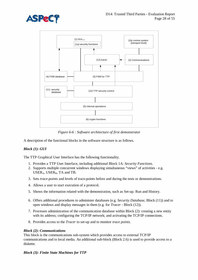
6.3.7 TTP software architectureThe TTP uses the general software structure described in [D07] as shown in Figure 6-6.
D14: Trusted Third Parties - Evaluation ReportPage 28 of 55
(1) GUITTP
(4) FSM database
(2) Communications
(6) crypto functions
(2a) comms system (transport level)
(12) tracer
(10) TTP security control(11) security database
(3) FSM for TTP
(5) internal operations
(1a) security functions
Figure 6-6 : Software architecture of first demonstrator
A description of the functional blocks in the software structure is as follows.
Block (1): GUI
The TTP Graphical User Interface has the following functionality.
1. Provides a TTP User Interface, including additional Block 1A: Security Functions.2. Supports multiple concurrent windows displaying simultaneous “views” of activities - e.g.
USERA, USERB, TA and TB.
3. Sets trace-points and levels of trace-points before and during the tests or demonstrations.
4. Allows a user to start execution of a protocol.
5. Shows the information related with the demonstration, such as Set-up. Run and History. 6. Offers additional procedures to administer databases (e.g. Security Database, Block (11)) and to
open windows and display messages in them (e.g. for Tracer - Block (12)).
7. Processes administration of the communication database within Block (2): creating a new entitywith its address; configuring the TCP/IP network; and activating the TCP/IP connections.
8. Provides access to the Tracer to set-up and to monitor trace points.
Block (2): CommunicationsThis block is the communications sub-system which provides access to external TCP/IPcommunications and to local media. An additional sub-block (Block 2.6) is used to provide access to adiskette.
Block (3): Finite State Machines for TTP
D14: Trusted Third Parties - Evaluation ReportPage 29 of 55
This software block defines all the finite state machine classes. One instant of a finite state machineclass represents one entity in the configuration. One application may represent one or more entities. Oneof the available finite state machines is chosen for each entity running on the PC. A single FSM isrequired for a TTP. In the first demonstrator only a single mode of operation supporting an end-userinterface will be provided. Future versions will support additional modes. The role of the FSM is
• to recognise TTP requests and protocol messages,• to analyse incoming protocol messages,• to formulate protocol response messages,• to identify security aspects, and• to initiate the appropriate sequence of actions in security control.
Block (4): FSM databaseThis block holds parameters used in the TTP finite state machine. These parameters can be written viathe GUI.
Block (5): Internal OperationsIn the general model in [D07], this block is titled Security Functions/Procedures. Here, TTP internaloperations are in this block. Details of the interface depend on the facilities that will be available fromthe ACRYL library, although it is currently anticipated that differences in, say, certificate willnecessitate some specific interface and operations here.
Block (6): Cryptographic FunctionsThis block contains the cryptographic algorithms and related computational facilities. These areprovided by the ACRYL library.
Block (7): ASN.1Not shown, as it is not planned to use ASN.1 in the first TTP demonstrator.
Block (8): WinsocksNot shown, as this block contains the standard Winsock libraries, and is accessed only via Block (2).
Block (9): Existing applicationsNot shown, as no existing applications are used by TTP.
Block (10): Security ControlIn the case of a TTP this could be integrated into the FSM block. It is currently a separate block whichchecks identified security issues
• initiates sequence of internal operations, and• passes results of internal operations back to FSM.
Block (11): Security DatabaseThe security database holds parameters specific to the security layer and is administered via the GUI.
Block (12): TracerThe tracer can display messages on a screen. The finite state machines instruct the tracer to display orsave messages. Trace-points are defined in the finite state machine.
This software architecture of the first TTP Demonstrator has the following interfaces.
FSM - TTP security control
D14: Trusted Third Parties - Evaluation ReportPage 30 of 55
This interface consists of the TTP functions implemented.TTP security control - TTP functions and operationsThis interface consists of the TTP internal operations implemented.TTP functions and operations - cryptographic functionsThis is the cryptographic interface. It is to be provided by the ACRYL API.
6.3.8 Criteria and Enhancements1. Critique of Demo 1 itself
The TTP architecture developed for the first TTP demonstrator meets the specifications indeliverables [D07] and [D09]. It works well.
2. General applicability
This architecture was specific to the first implementation, and provides a free-standing demonstrator.
For the future, the more general requirement is for an API to be called by a particular applicationrequiring protected communication, or possibly a protection package called by the user which pre-requests keys for communication with address-book entries, say.
3. Secure billing and trial requirements
It is required in the second demonstration and EXODUS based trial that the user and VASP willinsert the TTP and secure billing trial smart card, and the TTP will have a card reader
4. Enhancements
The following enhancements are suggested for the specification and implementation of the seconddemonstrator and the trial.
• Check and improve the TTP architecture used in the first demonstration to match the architectureof ASPeCT entities in the secure billing trial.
• Implement more complete and flexible TTP security information storage function.
• Provide a TTP service API.
6.4 Appearance of demonstration
6.4.1 First demonstration’s Graphical User InterfaceThe main objective of the first WP2.3 demonstration is to present a procedure for communication,supporting end-to-end encryption, through the use of TTP services. It comprises two clients, User A andUser B, located in different domains and the relevant pair of TTPs, one for each domain. User Acommunicates securely with User B with the intervention of their respective TTPs which collaborativelyperform the role of providing the users with key management services. Figure 6-7 illustrates the logicalconnections between the entities involved in the first demonstration.

D14: Trusted Third Parties - Evaluation ReportPage 31 of 55
User A User B
Figure 6-7 : The logical connections between entities
The GUI offers the possibility for the user to run one application, which simulates all the involvedentities in a single PC, or to assign the entities over a number of applications, which may run on one ormore PCs. In the latter case, the communication between the applications is provided via an EthernetLAN, using the TCP/IP protocol.
The protocol involves the four participants, namely two users, one as a sender (user A) and the other asa receiver (user B) and their corresponding TTPs, exchanging seven messages, as shown inFigure 6-8, in order to establish secure communication. First the two TTPs establish a shared secret keyamong them (messages M1 and M2). Then, user A sends his TTP a request for communication withuser B (message M3). In message M4, user A receives from TTP A the items he needs to prove hisidentity to the other party (a certificate) and compute the secret key that the two users will share. Now,user A is ready to send the certificate and his message, encrypted with the secret shared key, to User B,in M5. Finally, user B and TTP B exchange messages M6, M7, in order for user B to verify A’s identityand compute the shared key.
This is the minimum amount of information that the demonstration user needs to know, in order tounderstand the interactions he will enable.
user Auser A TTP ATTP A TTP BTTP B user Buser B
M 1M 1M 2M 2
M 3M 3M 4M 4M 5M 5
M 6M 6M 7M 7

D14: Trusted Third Parties - Evaluation ReportPage 32 of 55
Figure 6-8 : Demonstrated message exchange
6.4.2 The observer’s view
The role of the GUI is to provide the user with all the necessary means to initiate, observe and guide theend-to-end communication establishment process. From that point of view, the GUI must beunambiguous, detailed, informative and flexible against any improper user’s selections.In this first demonstration, the user is able to configure and view a series of important parameters aboutthe communication database, such as:
• type mode (server or client),• number of clients,• server IP address, and• client identity
and the involved entities, namely:• state• identity• secret, public and shared keys, and• certificate.
An overall graphical representation of the message flow is provided via the Monitor option, so that anyviewer of the demonstration can immediately have an idea of what is going on.The Tracer window, on the other hand, has the complementary role of providing the information neededfor observing the internal process, including key generation, certificates, entities’ state, etc., while theprotocol is running. Thus, the information contained in the Tracer window is intended for users that arefamiliar with the protocol and the scope of the demonstration, while these data also enable all users toverify the successful execution of the secure communication establishment procedure.
The demonstration is entirely driven by the GUI. First, the GUI user has to configure the communicationsubsystem and then he must “create” and register the four entities involved. Then, through the entities’Action menu items, he can initiate and steer the process of the end-to-end confidential communicationestablishment. To achieve this, he must follow the correct sequence of steps, described in the user guide.
Error messages are displayed when an improper selection is made. There are also some indicativemessages which appear in order to help the user follow the proper sequence of actions. Finally, there areinformative messages that confirm the successful completion of some actions. Thus, the GUI providesinformation to the demonstration user on the impact of his actions.
6.4.3 Suggestions for enhancement
The current implementation requires that the demonstration user possesses either a minimum of relatedbackground or a small user guide. The addition of the on-line help will fulfil that requirement.Some improvements can be made concerning the displayed messages in Monitor window, since nowthese are only indicative. This improvement would allow the message flow to be more intelligible for aproject-unrelated user.

D14: Trusted Third Parties - Evaluation ReportPage 33 of 55
The Tracer window can also be enhanced to support options, for example to save or print the presentedmessages, so that they can be viewed off-line. An option initiating the automatic execution of theprotocol can be added. This alternative will facilitate performance measurements and allow users tosimply observe the procedure rather than conducting it.
6.5 User-friendliness
6.5.1 Quality of Service
Among many definitions, it can be generally assumed that Quality of Service (QoS) is determined by theuser’s perception of the degree to which the service meets, or surpasses, the need for which it isdesigned. It may also be defined by the level of overall user satisfaction regarding the provided service.QoS is defined in [ITU94] as follows: “The collective effect of service performance which determine thedegree of satisfaction of a user of the service”. This definition of QoS is a wide one, encompassing manyareas. The QoS parameters, such as user satisfaction, are subjective in nature, depending on individualperceptions and expectations.
As derived from [ITU93], the user-oriented QoS parameters provide a valuable framework for design,but they are not necessarily practical for specifying performance requirements. Similarly, theperformance parameters ultimately determine the user-observed QoS but they do not necessarilydescribe that quality in a way that is meaningful to users.
6.5.2 GUI features and suitability
The Graphical User Interface enables the user to configure the communication database and to observeand guide the end-to-end confidential communication establishment process. Thus, the GUI must bedesigned according to the user’s needs. In order to estimate the GUI’s friendliness for the user, severalpoints are considered, such as:
The overall appearance: The GUI provides a simple visual representation of the demonstrated protocolthrough the Monitor bitmaps and an accurate record of all interactions through the Tracer window.The flexibility: The demonstration is flexible regarding potential misuse by the users. There aremessages that appear when the user makes inapplicable selections, in order to help them define theproper sequence of actions.The sufficiency of the displayed features: The user has the options of configuring the communicationdatabase and the entities involved and watching the message flow in an abstract (Monitor option) orconcrete way (Tracer option).The degree of detail of the displayed information: The Tracer window enables the user to observe andunderstand the internal actions that are not presented in the main GUI window (key generation,certificates, etc.). Also, detailed information on the involved entities’ features is included in the Statuswindows for the user’s convenience.The degree of guidance of the user on the steps he must follow: The menu bar is designed in a waythat all the actions can be selected sequentially. The on-line Help option that will be available in thefuture is intended to include more extensive information about the GUI features and the recommendedsuccession of user actions.The security functions impact as perceived by the user: The duration of the security functionsexecution is not perceivable by the user.

D14: Trusted Third Parties - Evaluation ReportPage 34 of 55
6.6 Performance
6.6.1 Methodology
The performance of the first demonstrator was evaluated by making a number of timing measurementsof the processing delays involved during execution of the protocol. Following the full protocoldescription in Appendix C (Section 8.3), the protocol was divided into four parts and the processingdelays involved for each part were treated separately. Where timings were appropriate, estimates of theprocessing delays were made by measuring the delays between fixed measuring points. Thesemeasuring points are indicated in Figure 6-9 and Figure 6-10. Each timing was measured five times andan average measurement was computed and taken as a basic estimate of the processing delay. Theresults are shown in Tables 1 to 6.
All timings were made using an INTEL 486 33,4 Mhz.
6.6.2 Estimates of processing delays
Part 1: Share a secret between two TTP’s
Part 1 can be conducted off-line, and thus no secure communication timings were taken for this part ofthe demonstrator operation.
Part 2 : Certificate generation in A’s domain
The measurement points for Part 2 are indicated in Figure 6-9.
Aa
Bb
TAtA
TBtB
TPR09
TPS03
TPR12
TPS04
B
CertTA(ga) a, gb
User input via GUIDelta1
Delta2
Figure 6-9 : Measurement points for Part 2
Two measurements are provided for Part 2 of the protocol. Firstly user A prepares a request to send toTA (TPR09 - TPS03) and then TA generates a certificate and key values for A. Due to a minortechnical problem it was not possible to obtain estimates of the full processing time of the certificategeneration process during Part 2. However most of this process was measured (TPR12 - TPS04) andthe remaining time Delta1 represents the time taken to generate a user window in the demonstrator, andcan be considered as negligible. A similar technical problem prevented a processing delay estimate being

D14: Trusted Third Parties - Evaluation ReportPage 35 of 55
calculated for the generation of the session key at user A. This measurement is represented in Figure 6-9as Delta2 and corresponds to one exponentiation.
The measured delays during Part 2 are shown in Table 1 (seconds.milliseconds).
TPR09 TPS03 Time at A TPR12 TPS04 Time at TA Time at A and TA19.570 19.630 0.060 26.990 37.640 10.650 10.71021.380 21.380 0.000 50.760 01.470 10.710 10.71004.310 04.310 0.000 15.510 26.220 10.710 10.71018.620 18.620 0.000 41.360 52.070 10.710 10.710
Table 1 : Measured delays during Part 2
The average processing delay during Part 2 (excluding timings Delta1 and Delta2) is thus 10.710seconds.
Parts 3 and 4 : Message transmission from A to B and certificate generation in B’s domain
The measurement points for Parts 3 and 4 are indicated in Figure 6-10.
Aa
Bb
TAtA
TBtB
TPR10
TPS05TPR05
TPS06
ga,b
CertTA(ga)
User input via GUI
TPR06
TPS07 TPR07
TPS08
CertTA(ga),gb,eKAB(m)
Figure 6-10 : Measurement points for Parts 3 and 4
The first measured delay was that of the sending user (user A) as they prepare the message to be sent toB (TPR10 - TPS05). This processing includes one encryption and the delays are shown in Table 2(seconds.milliseconds).
TPR10 TPS05 Time at A01.530 01.960 0.43011.970 12.410 0.44017.570 17.950 0.40037.870 38.250 0.47035.320 35.650 0.330

D14: Trusted Third Parties - Evaluation ReportPage 36 of 55
Table 2 : Delay at A during Parts 3 and 4
The average processing delay at A during Parts 3 and 4 is thus 0.414 seconds.
At the receiving end there are two sources of processing delay - user B and TB. The delay at TB(TPR06 - TPS07) is largely taken up by a certificate verification and the measured delays(seconds.milliseconds) are shown in Table 3.
TPR06 TPS07 Time at TB03.610 14.930 11.32013.950 25.320 11.37019.490 30.860 11.37039.950 51.380 11.43037.300 48.670 11.370
Table 3 : Delay at TB during Parts 3 and 4
The processing delay at TB during Parts 3 and 4 is thus 11.372 seconds.
The processing delay at B consists of two stages. Firstly B extracts a certificate for the messagereceived from A and forwards this to TB (TPR05 - TPS06). Then later B computes the session keyfrom information received from TB and decrypts the message (TPR07 - TPS08). The measuredprocessing delays at B are indicated in Table 4 (seconds.milliseconds).
TPR05 TPS06 Time at B TPR07 TPS08 Time at B Total time at B02.020 03.500 1.480 15.200 19.930 4.730 6.21012.410 13.900 1.490 25.540 30.320 4.780 6.27017.950 19.380 1.430 31.080 35.800 4.720 6.15038.360 39.850 1.490 51.490 56.320 4.830 6.32035.710 37.190 1.480 48.830 53.560 4.730 6.210
Table 4 : Delay at B during Parts 3 and 4
The average processing delay at B during Parts 3 and 4 is thus 6.232 seconds.
Table 5 indicates the total processing delay involved at the receiving end (TPR05 - TPS08). This delayinclude processing at both user B and TB.
TPR05 TPS08 Time at B and TB02.020 19.930 17.91012.410 30.320 17.91017.950 35.800 17.85038.360 56.320 17.96035.710 53.560 17.850
Table 5 : Total delay at B and TB during Parts 3 and 4
The average processing delay at B and TB during Parts 3 and 4 is thus 17,896 seconds.
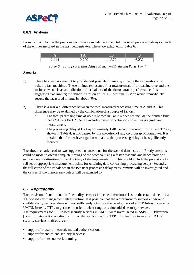
D14: Trusted Third Parties - Evaluation ReportPage 37 of 55
6.6.3 Analysis
From Tables 1 to 5 in the previous section we can calculate the total measured processing delays at eachof the entities involved in the first demonstrator. These are exhibited in Table 6.
A TA TB B0.414 10.700 11.372 6.232
Table 6 : Total processing delays at each entity during Parts 1 to 4
Remarks
1) There has been no attempt to provide best possible timings by running the demonstrator onsuitably fast machines. These timings represent a first measurement of processing time and theirmain relevance is as an indication of the balance of the demonstrator performance. It issuggested that running the demonstrator on an INTEL pentium 75 Mhz would immediatelyreduce the measured timings by about 40%.
2) There is a marked difference between the total measured processing time at A and B. This
difference may be explained by the combination of a couple of factors:• The total processing time at user A shown in Table 6 does not include the omitted time
Delta2 during Part 2. Delta2 includes one exponentiation and is thus a significantmeasurement.
• The processing delay at B of approximately 1.480 seconds between TPR05 and TPS06,shown in Table 4, is not caused by the execution of any cryptographic primitives. It ispossible that further investigation will allow this processing delay to be significantlyreduced.
The above remarks lead to two suggested enhancements for the second demonstrator. Firstly attemptscould be made to obtain complete timings of the protocol using a faster machine and hence provide amore accurate estimation of the efficiency of the implementation. This would include the provision of afull set of appropriate measurement points for obtaining data concerning processing delays. Secondly,the full cause of the imbalance in the two user processing delay measurements will be investigated andthe causes of the unnecessary delays will be attended to.
6.7 ApplicabilityThe provision of end-to-end confidentiality services in the demonstrator relies on the establishment of aTTP-based key management infrastructure. It is possible that the requirement to support end-to-endconfidentiality services alone will not sufficiently stimulate the development of a TTP infrastructure forUMTS. Instead, TTPs might need to offer a wider range of value-added security services.The requirements for TTP-based security services in UMTS were investigated in ASPeCT Deliverable[D02]. In this section we discuss further the application of a TTP infrastructure to support UMTSsecurity services in three areas:
• support for user-to-network mutual authentication;• support for end-to-end security services;• support for inter-network roaming.

D14: Trusted Third Parties - Evaluation ReportPage 38 of 55
6.7.1 Support for user-network mutual authenticationMany of the user-network mutual authentication schemes proposed for UMTS are based on public keycryptography. As such they require that the entities in the protocol can obtain authentic copies of thepublic keys they need. In this scenario a TTP could provide key management services to users, whichwould include the certification and provision of public keys. Typically, authentic copies of public keyscould be made available as certificates generated and issued by a TTP acting as a certification authority.
In a simple scenario where the user just needs to authenticate with one network, authentic copies ofpublic keys and associated private keys could be distributed by interacting with the TTP off-line. Forinstance, the keys could be distributed by the TTP as part of smart card pre-personalisation. However,in order to be able to enhance the level of security, the user or network may also require on-line accessto a TTP in order to request updates on public keys, or to check or request appropriate revocation lists.In the more general case, the user will need to be able to register and authenticate with differentnetworks, with which it has had no previous security association. In this case the relevant authenticpublic keys could be made available through a trusted infrastructure of TTPs acting as certificationauthorities and certificate servers.
6.7.2 Support for end-to-end security servicesThe TTP infrastructure can allow two users who have had no previous security association to establishsecure communications by receiving trusted services from their respective TTPs. A TTP infrastructurecould be used in support of a wide range of security services for end users. In the following we describethe role of TTPs in support of some of these services.
6.7.2.1 ConfidentialityA TTP infrastructure can provide the means to allow UMTS users to establish confidentialcommunication channels with other users, possibly in different countries, whilst being able to satisfy lawenforcement requirements at both the national and international level. This is the service provided in thedemonstrator.
In the demonstrator a TTP-based key management scheme allows the users to establish a shared secretconfidentiality key for use in a symmetric cryptosystem. An important feature of the scheme is that someinformation used to generate the shared secret confidentiality key is escrowed to the TTPs. Thus, aninterception agent can, under certain prescribed conditions, obtain access to communications betweenthe users by presenting a valid warrant to an appropriate TTP, who releases the escrowed information.
Note that it is important that only keys used for confidentiality can be recovered from the TTP. It shouldnot be possible for an agent to obtain secret signature keys, or keys used for integrity protection, forexample. Therefore, care must be taken in distinguishing TTP services that support confidentiality, fromTTP services that support integrity, authentication, access control and non-repudiation.
6.7.2.2 Data integrity and origin authenticationA TTP infrastructure could also be used to help users establish a shared secret integrity key for use ingenerating a message authentication code (MAC). This type of service would allow users to protect theirmessages against unauthorised modification. It also allows receivers to be sure of the true identity of thesender.
Digital signatures could also be used to support message integrity and origin authentication. In this casethe TTP infrastructure could be used to manage the asymmetric key pairs required to support the digitalsignature scheme. Typically, the TTPs would act as certification authorities and certificate servers forthe public keys to be used in the scheme.
D14: Trusted Third Parties - Evaluation ReportPage 39 of 55
6.7.2.3 Entity authenticationIt is likely that some users and services may require a mechanism whereby end users of a UMTStelecommunications service can mutually authenticate each other. For basic telephony services this isunlikely to be a requirement. However, for non-telephony services, where users interact with servicesprovided by other users acting as value-added service providers, a cryptographic means of user-to-userauthentication may be a strong requirement. Note that in implementing user-to-user authentication, itmay be desirable to re-use the user-network mutual authentication mechanism.
In supporting entity authentication a TTP can be used as an authentication server in schemes thatinvolve third parties. The services can be categorised according to whether the authentication server ison-line, off-line or in-line.
6.7.2.3.1 On-line authenticationIn symmetric authentication schemes, there is a requirement for every verifier to maintain a secretsymmetric key with every claimant. This may not be practical for end-to-end user authentication.Instead, a trusted on-line authentication server could be introduced. This would share a secret key withevery claimant and verifier. Two general approaches to this scheme are outlined below:
• In the first approach, the claimant encrypts or seals a message with its secret key and sends it to theverifier. Since the verifier does not share the claimant’s key, it must obtain it through a separateexchange with the server. This exchange should be secured using a shared key between the serverand the verifier.
• In the second approach, the claimant first obtains a ticket from the server which contains a secret keyto be used by the claimant to authenticate itself. The communication with the server is protectedusing a secret key shared between the server and the claimant. After the exchange, the claimantauthenticates itself by encrypting or sealing a message with the secret key it received from the serverand sending it to the verifier for checking.
The major disadvantage of this approach is that the users require on-line access to the TTP during theauthentication process. This may not be practical for end-to-end user authentication in UMTS.
6.7.2.3.2 Off-line authenticationWith asymmetric authentication the need for the authentication server to be on-line is removed. Instead,verifiers can obtain certified public keys for claimants and certificate revocation lists from an off-lineserver, prior to or during authentication. This information can be cached and reused to avoid having tocommunicate with the server each time authentication is initiated. However, if a user wants to beabsolutely certain that a certified public key has not been revoked it should verify the status of thecertificate or the certificate revocation list with the server. An off-line authentication server may actsimply as a directory server for certificates generated by another TTP acting as a certification authority.
6.7.2.3.3 In-line authenticationIn-line authentication involves an authentication server positioned in the communication path betweenclaimant and verifier. The authentication is, in effect, split into two sets of interactions. Firstly, theclaimant attempts to authenticate itself to the server, which vouches for the identity of the verifier.Secondly, the verifier attempts to authenticate the server, which vouches for the identity of the claimant.
The major disadvantage of this approach is that the authenticated channel is set up via a TTP, thereforesubsequent messages passed between the users may have to be sent via the TTP. This may have aserious impact on performance in a UMTS environment.

D14: Trusted Third Parties - Evaluation ReportPage 40 of 55
6.7.2.4 Access controlUsers may wish to obtain access privileges in order to be able to access services or data provided byother end users. In this scenario a TTP infrastructure may be used to certify and manage privileges foraccess control. Certified privileges may be obtained from a TTP in the form of a Privilege AttributeCertificate (PAC).
The PAC will contain a list of resources that the user may wish to access and the associated privilegelevel that the user has been assigned. A user will send a request for a given privilege attribute to a TTP,which will then identify and authenticate the user. If the current security policy states that the user isauthorised to make the requested access, then the TTP will generate and certify the privilege attribute.The privilege attribute certificate is then distributed by the TTP by publishing it in a directory.
The veracity of privilege information can be checked on demand by anyone who obtains the TTP’spublic certification key. The PAC may need to be revoked if changes in access control privileges arerequired, or if a compromise of sensitive information is suspected.
6.7.2.5 Non repudiationIt is possible that end users will require protection against repudiation of origin or delivery of messagessent to other uses. This type of service may be particularly important where a user interacts with anotheruser, acting as a value-added service provider, in order to receive a chargeable service. In this case, inorder to ensure that charging is incontestable, the parties involved should have the assurance thatjustified claims relating to charges can be proved and that unjustified claims cannot be successfullymade. A non repudiation service can be used to provide incontestable charging by generating evidencewhich can be used to prove that the user invoked certain chargeable actions.Non repudiation involves the generation, verification and recording of evidence about a particular eventor action, and the subsequent retrieval and re-verification of this evidence in order to resolve disputes. ATTP infrastructure may have an important role to play in each phase of a non-repudiation service.
Evidence may be generated by digitally signing information related to a specific event or action.Information may include the identities of the entities involved, the communicated data, and the date andtime. Additional information that may be required could include the mode of transfer, the location ofentities or the creator of data. The evidence may be generated by the evidence subject, perhaps inconjunction with a TTP, or by a TTP alone. In the case where digital signatures are used, a TTPinfrastructure could be used to manage the asymmetric key pairs require to support the digital signaturescheme.A TTP may also have to record evidence in a non-repudiation role so that it can be retrieved by anevidence user or adjudicator. The evidence to be recorded will typically be received via an interface withthe network over which the communication entities are sending messages. The recording process mayinvolve the addition of a time-stamp and certain user-related information.
The purpose of evidence verification is to provide the evidence user with the confidence that the suppliedevidence will be adequate in the event of a dispute. The evidence verifier may be the evidence user, or aTTP trusted by the evidence user. For evidence generated using digital signatures, evidence verificationwill involve verification of the digital signature. In dispute resolution, a TTP could act as an adjudicatormaking a decision, based on evidence collected, to resolve the dispute.
6.7.3 Support for inter-network roamingIn UMTS it is likely that there will be an extremely large number of network operators providing a widerange of mobile telecommunication services to users. The requirement to provide global coverage willnecessitate that UMTS users can roam freely between networks. It is assumed that in order for a user to

D14: Trusted Third Parties - Evaluation ReportPage 41 of 55
be able to roam onto a given network, his service provider must have some kind of roaming agreementestablished with that network.
In GSM roaming is facilitated by a set of procedures laid out by the GSM MoU Association. Inparticular, the MoU specifies procedures for establishing written bi-lateral roaming agreements betweenMoU members. Procedures also exist to facilitate the establishment and testing of signalling linksbetween networks. Currently, the management and administration of roaming agreements in GSM ismanageable because each operator operates under the control of the MoU, which effectively acts as aregulatory body. Moreover, the number of operators involved is relatively low. Thus, there is arelatively high degree of trust among operators which allows roaming agreements to be established moreeasily.
However, it cannot be assumed that all UMTS operators world-wide would be willing to join such anMoU. Also, the cost and complexity of roaming trials and agreements between a large number ofoperators world-wide would be very difficult to support. Even within the GSM community, it is widelyaccepted that a complete set of bi-lateral roaming agreements between every GSM network will never beachieved due to the administration and costs involved. Currently, of the approximately 20,000 potentialworld-wide roaming agreements, only around 1,500 are currently in place, and of those there are asignificant number whose volume of traffic do not justify their maintenance costs.The establishment of roaming agreements will become even more cumbersome in UMTS as the numberof network operators and service providers increases. Moreover, the trust relationships between thenetwork operators and service providers will become more complex because of the potential lack of aregulatory body similar to the GSM MoU and because of the number of entities involved. Therefore, itis likely that alternative mechanisms will be required for UMTS. One approach may be to make use of aTTP infrastructure to help manage the trust relationships between network operators and serviceproviders and thus support the establishment of roaming agreements.
6.7.3.1 Mechanisms to facilitate roaming in GSMIn GSM various mechanisms have been established in order to reduce the cost of setting up roamingagreements between network operators. For instance, clearing houses can be introduced to reduce thecost associated with exchanging billing information. This significantly reduces the cost in cases wheresmall individual amounts of billing information need to be sent to a large number of operators. In thisway an operator need only interact with one clearing house in order to exchange billing information withmany operators.
The cost of establishing roaming between networks can also be reduced by introducing an intermediarywhich acts as an relay point for signalling information sent between networks. Thus, instead of settingup bi-lateral signalling links with many other networks, links would only need to be established with arelay point. This would significantly reduce the cost associated with the establishment and subsequenttesting of signalling links.
In both scenarios the network operator would need to set up agreements with the clearing house orsignalling relay point in order to negotiate and agree conditions. If the roles of clearing house andsignalling relay point are combined then the combined agreement can effectively replace bi-lateralroaming agreements between operators.
Recently, within the GSM community, a scheme has been established, which facilitates theestablishment of roaming agreements through the use of a combined International Roaming Platform(IRP) to handle signalling traffic and a clearing house facility to handle the exchange of billinginformation [GCS97]. The Global Cellular Service involves the establishment of written agreementsbetween the network operator and the entity offering the service. This means that individual bi-lateral

D14: Trusted Third Parties - Evaluation ReportPage 42 of 55
roaming agreements between network operators are no longer required. This is a particularly attractivesolution in cases where the amount of roaming traffic is low.
6.7.3.2 The application of a TTP infrastructure to facilitate roaming in UMTSWe now consider how a TTP infrastructure could be used to facilitate roaming in UMTS.
6.7.3.2.1 Support for electronic roaming agreementsIn UMTS it would be desirable to avoid having to exchange written bi-lateral agreements as part ofestablishing roaming between a service provider and a network operator. For instance, it might bedesirable for roaming agreements to be set up dynamically, as and when they are required (e.g. on a percall basis). Clearly, this cannot be implemented if the exchange of written documents is required.In the first instance we consider how electronic roaming conditions could be negotiated and agreed off-line. We then consider how electronic agreements could facilitate the on-line establishment of roaming.
Before negotiating and establishing a roaming agreement electronically, a network operator and serviceprovider will have to mutually authenticate each other. After authentication has been performed roamingconditions could be negotiated and agreed. When an agreement has been reached, the service providercould commit to the conditions by signing them using a digital signature. To support this procedure anetwork of TTPs could be used to provide a certification infrastructure which would enable networkoperators and service providers to mutually authenticate each other, and subsequently allow serviceproviders to sign a roaming agreement.
This procedure could also facilitate the on-line establishment of roaming agreements. In this case weassume that a UMTS subscriber, wishing to gain access to a network, sends the identify of its serviceprovider to the network. The network could then initiate the on-line establishment of a roamingagreement with the user's service provider using the electronic procedures described above. The roamingagreement may be established for this particular user access, or it may apply to subsequent accesses byany user of the particular service provider concerned.
If the roaming agreement only applies to particular user accesses, then the network operator could givethe service provider a statement containing specific call related information (e.g. the identity of the user,the charging rate and a time stamp). If the service provider is satisfied with the terms of the statement hewill sign it with his unique digital signature and this will be his commitment to pay for the servicesprovided to the subscriber. However, if the roaming agreement applies to subsequent user accesses, thenthe agreement will specify the long term roaming conditions which apply.
Further study is required into an appropriate certification infrastructure based on TTPs for the supportof electronic roaming agreements in UMTS. It is also necessary to study the feasibility of the on-lineestablishment of roaming agreements in UMTS.
6.7.3.2.2 Reducing the number of bi-lateral agreementsIn UMTS it is likely that in many cases the amount of roaming traffic associated with a particularservice provider / network operator pair is unlikely to justify the cost of managing and maintainingindividual bi-lateral roaming agreements. Thus, it may be desirable to avoid having to establishindividual bi-lateral roaming agreements between every network operator / service provider pair.One approach to reduce the cost of establishing individual bi-lateral roaming agreements may be toestablish roaming agreements only when they are required. In this case roaming agreements may applyto individual accesses to a network, or they may apply to all subsequent accesses by users of theparticular service provider concerned. The choice here will depend on the likely amount of roaming

D14: Trusted Third Parties - Evaluation ReportPage 43 of 55
traffic associated with the particular service provider / network operator pair. This approach assumesthat roaming agreements can be established on-line, as described in Section 6.7.3.2.1 above.An alternative, but potentially complementary approach, for reducing the cost of managing andmaintaining individual agreements, would be to group service providers and network operators in TTPdomains. Instead of establishing individual bi-lateral agreements between each network operator /service provider pair, agreements would be established between a TTP and each of the service providersand network operators in its domain.
For each service provider, the agreement would specify the conditions to be applied by each network itwishes its users to be able to roam with. For each network operator the agreement would specify theconditions to be applied by each service provider whose users are permitted to roam on the operator'snetwork. Thus, when a user attempts to access a network, the appropriate roaming agreement can beobtained and verified by the network operator. In the case where more than one TTP is involved, it maybe necessary to verify a chain of certificates before being able to verify the appropriate roamingagreement.
TTPs offering this type of service could also act as clearing houses for billing information or relaypoints for signalling information in a similar way to that described in Section 6.7.3.1 above.
7. Summary of suggested enhancements
In summary, the first TTP demonstrator meets the specifications of [D07] and [D09] and runs well.There are however a number of suggested enhancements for the implementation of the seconddemonstrator. These have been described throughout Section 6 and we provide a brief summary here.
The most significant direction to future enhancements is provided by the need to integrate with thesecure billing demonstrator and the trial with EXODUS. Further study is needed before it can beprecisely stated what changes to the current demonstrator are needed to successfully navigate thisintegration process, however some likely enhancements are as follows:
• Key escrow protocol. The protocol implemented in the first demonstrator is unlikely to be perfectlysuitable for implementation in the second demonstrator. Clarification of likely escrow scenarios isnecessary. Either the existing protocol will be subject to some suitable refinements or alternativeprotocols will be considered. If the existing protocol is adapted then some extra provision for time-bounded interceptions is a likely enhancement.
• Security Aspects. More TTP services, functions and internal operations could be provided.Suggested services include key revocation and certification for access control and time-stamping.These services are a priority because they are services likely to be demanded on integration with thesecure billing demonstrator.
• Architecture. The architecture should be matched with that of the secure billing trial. A morecomplete and flexible TTP security information storage function should be provided as well as aTTP Service API.
• Demonstrator Appearance. Suggested enhancements include the addition of an on-line help,improvements in Monitor message display, extra Tracer options to permit off-line viewing and anautomatic protocol execution option. Note that other minor refinements to the first demonstratorcould include an explicit demonstration of key recovery (rather than an implicit one) and an option

D14: Trusted Third Parties - Evaluation ReportPage 44 of 55
to slow down certain screen operations (such as message arrow display) to ease visualcomprehension of the protocol message sequence.
• Implementation. Implementation refinements arising from analysis of the first demonstrator shouldbe incorporated into the second demonstrator.
8. Appendix
8.1 Appendix A: Two-way key escrow protocolsThis appendix contains supplementary information relevant to Section 6.1.5.3.
We consider here some simplified protocols that have appeared in ASPeCT related documents. In thefollowing protocols user A establishes a session key for communication with user B. Each user has ahome TTP (TA for A, and TB for B) with which they can communicate (securely). Some of theprotocols require a secure link between TA and TB. Note that we have simplified all the protocols forease of comparison.
In the illustrations of the protocols a value appearing in the column of entity X means that entity Xgenerates that value. An arrow and values between column X and column Y indicate transfer of valuesbetween entity X and entity Y (dotted lines in the column of entity X indicate that the value beingtransferred is not sent to that entity).
Protocol IA A TA TB Ba g a →
b b← gb b →
g a → ....... → ....... →
Protocol 1A is an earlier version of the protocol in [JMW96b]. At the end of the exchange A and B canboth compute the key g ab . In Protocol IA, b is a function of the identities of TA, TB and B. Thisprotocol is a one-way protocol and we simply adopt the one-way key as a two-way key.
Protocol IBA TA TB Ba g a →
b b← gb b →
← g b1 b1a1 a1
← a1 g a1 →

D14: Trusted Third Parties - Evaluation ReportPage 45 of 55
g a → ....... → ....... →← ....... ← ....... ← g b1
Protocol IB simply consists of two runs of Protocol IA, one in each direction, and a subsequentcombination of the two one-way keys. At the end of the above exchange A and B can both compute thekeys g ab (for communication from A to B) and g a b1 1 (for communication from B to A). Two-waycommunication could now be established by using some combination of these two keys, perhapsg gab a b+ 1 1 . In Protocol IB, b is determined as a function of the identities of TA, TB and B, and a1 isdetermined as a function of TA, TB and A.
Protocol IIAA TA TB B
ab b
← a gb, b →
g a → ....... → ....... →Protocol IIA is the original one-way protocol of [JMW96b]. At the end of the previous exchange A andB can both compute the keys g ab . In Protocol IIA, b is a function of the identities of TA, TB and B.We simply adopt the one-way key as a two-way key.
Protocol IIBA TA TB B
ab b
← a gb, b →
b1a1 a1
← a1 b g a1 1, →
g a → ....... → ....... →← ....... ← ....... ← g b1
Protocol IIB simply consists of two runs of Protocol IIA, one in each direction, and a subsequentcombination of the two one-way keys. At the end of the above exchange A and B can both compute thekeys g ab (for communication from A to B) and g a b1 1 (for communication from B to A). Two-waycommunication could now be established by using some combination of these two keys, perhapsg gab a b+ 1 1 . In Protocol IIB, b is determined as a function of the identities of TA, TB and B, and a1is determined as a function of TA, TB and A.
Protocol IIIA TA TB Ba a → ← b b

D14: Trusted Third Parties - Evaluation ReportPage 46 of 55
k A
a k A → b →k B
← b k B
← g bk kA B g ak kA B →
Protocol III is a reduction of the protocol of [CGM96]. At the end of the above exchange A and B canboth compute the key g abk kA B . In Protocol III, k A is determined as a function of the identities of TA, Aand B, and k B is determined as a function of TB, A and B.
Protocol IVA TA TB Ba g a → ← gb b
k A k B
← g k A g k B →
g ga k A → ....... → ....... →← ....... ← ....... ← g gb k B
Protocol IV is a reduction of the protocol of [CM96]. At the end of the exchange A and B can both
compute the key g ga k A b kB+. In Protocol IV, k A is a function only of the identity of TA, and k B is
determined as a function only of TB.
Protocol VA TA TB B
a b← a b →
g a → ....... → ....... →← ....... ← ....... ← gb
Protocol V is a basic escrow version of the original Diffie-Hellman key exchange [DH76]. At the end ofthe above exchange A and B can both compute the key g ab .
First we make some comments on parameter differences among the protocols (see Section 6.1.2.1).
Communication Structure• All protocols need links between A and TA, B and TB and between A and B.• All protocols except Protocol IA and Protocol IV require a secure link between A and TA.• All protocols except Protocol IV require a secure link between B and TB.• Protocols IA, IB, IIA and IIB require a secure (off-line) link between TA and TB.• Protocol III requires an on-line secure link between TA and TB.

D14: Trusted Third Parties - Evaluation ReportPage 47 of 55
Cryptographic flexibility: Key Generation• In Protocol IA the session key is generated jointly by A, TA and TB.• In Protocols IB, III and IV the session key is generated jointly by A, B, TA and TB.• In Protocols IIA, IIB and V the session key is generated jointly by TA and TB.
Interception safeguardsIn each protocol an interception authority can obtain the session key by approaching either TTP. Weconsider possible releases of information for the various protocols.
Protocol IA :• TA or TB release b . All messages between users with home TTP TA and B (initiated by the user
with home TTP TA) can be read for the lifetime of key b ;• TA or TB release g ab . All messages from A to B (initiated by A) can be read for the joint lifetime
of keys a and b .
Protocol IB :• TA or TB release b and a1. All messages between A and B can be read for the joint lifetimes of
keys b and a1;• TA or TB release g gab a b+ 1 1 . All message between A and B can be read for the joint lifetimes of
keys a b a, , 1 and b1 .
Protocol IIA :• TA releases a . All messages between A and any user (initiated by A) can be read for the lifetime of
key a ;• TA or TB release b . All messages between users with home TTP TA and B (initiated by the user
with home TTP TA) can be read for the lifetime of key b ;• TA or TB release g ab . All messages from A to B (initiated by A) can be read for the joint lifetime
of keys a and b .
Protocol IIB :• TA release a and a1 . All messages between A and B can be read for the joint lifetime of keys
a and a1 ;• TB release b and b1 . All messages between A and B can be read for the joint lifetime of keys b and
b1 ;• TA or TB release b and a1 . All messages between A and B can be read for the joint lifetime of
keys b and a1 ;• TA or TB release g gab a b+ 1 1 . All messages between A and B can be read for the joint lifetimes of
keys a b a, , 1 and b1 .
Protocol III :• TA or TB release g abk kA B . All messages between A and B can be read for the joint lifetime of keys
a b k A, , and k B .
Protocol IV :• TA releases k A . All messages between A and B can be read for the lifetime of key k A ;

D14: Trusted Third Parties - Evaluation ReportPage 48 of 55
• TA releases g ak A .All messages between A and B can be read for the lifetime of keys a and k A ;• TB releases k B . All messages between A and B can be read for the lifetime of key k B ;
• TB releases g bkB .All messages between A and B can be read for the lifetime of keys b and k B .
Protocol V :• TA releases a . All messages between A and B can be read for the lifetime of key a ;• TB releases b . All messages between A and B can be read for the lifetime of key b
The most significant differences among the five protocols occur with respect to the communicationstructure. Protocol III requires on-line secure communication between TA and TB which for manysituations, including within ASPeCT, is fairly impractical. Protocol IV in contrast requires no securelinks between any of the entities. Note that our basic ASPeCT communication scenario does not requirethis lack of secure links.
There does not seem to be a great deal of difference between Protocols IB, IIB, III, IV and V withrespect to types of interception possible. All only obviously permit interception of messages directlybetween users A and B (although in Protocols IV and V wider interceptions might be possible dependingon the scope of use of key information generated by TA and TB). If a wider interception is required thenextra information will have to be released. In contrast Protocols IA and IIA allow certain widerinterceptions to take place. In this respect it can be claimed that Protocols IA and, particularly, IIA aremore efficient from the point of view of interception authorities.
The extra complexity of Protocols IB and IIB does not seem to have any distinct advantages over thesimpler Protocol V. Indeed Protocol IV has the additional attraction of reducing the use of secure linksbetween the main entities. Neither do there seem to be any significant advantages of using Protocol IBover IA, and of using Protocol IIB over IIA. The notable difference between Protocols IB and IA is thatboth users can contribute to the generation of the session key in IB, but as B trusts TB (who contributesto the key generation in Protocol IA) this does not seem a significant gain. These remarks aresummarised in Section 6.1.5.2.
8.2 Appendix B: Some alternative escrow protocolsThis Appendix provides details relevant to Section 6.1.6.
8.2.1 LWY protocolThe following protocol is referred to as the LWY protocol and was proposed in [LWY95].Let p and q be large primes, such that q divides p − 1 , and let g be an element of order q (modulo
p ). Let S x P x( ), ( ) be the secret and public keys of X, where P x g S x( ) ( )= (modulo p ). Let E be asecure block cipher and H be a one-way hash function. Values p q g E, , , and H are all public.In advance of communications1. User A selects a TTP in each domain that requires access to the future communication. Let A select
TTP TA, and let B select TTP TB.2. User A generates S a P a( ), ( ) , while user B generates S b P b( ), ( ) .3. S a( ) is escrowed to TA , while S b( ) is escrowed to TB.Note that in step 2 we assume that the users generate their own secret and public keys. However, in[LWY95] it is not specified who generates these keys.At time of communication1. A computes the following:

D14: Trusted Third Parties - Evaluation ReportPage 49 of 55
K a b d H P b dS a( , , ) ( ( ) , )( )=S a d H S a d( , ) ( ( ), )=S a b d H S a d P b( , , ) ( ( , ), ( ))=
2. B computes the following:K b a d H P a dS b( , , ) ( ( ) , )( )=S b d H S b d( , ) ( ( ), )=S b a d H S b d P a( , , ) ( ( , ), ( ))=
3. A sends E K a b dS a b d( , , ) ( ( , , )) to B.
4. B sends E K b a dS b a d( , , ) ( ( , , )) to A.
Users A and B can now exchange messages using session key K a b d K b a d( , , ) ( , , )= .Key recoverySeveral types of interception are possible using the LWY protocol:• TA releases S a( ) . All messages from or to A can be read for the lifetime of S a( ) .• TA releases S a d( , ) . All messages from or to A can be read for the joint lifetime of S a( ) and
date-stamp d .• TA releases S a b d( , , ) . All messages between A and B can be intercepted for the joint lifetime of
S a( ) , S b( ) and date-stamp d .• TB releases S b( ) . All messages from or to B can be read for the lifetime of S b( ) .• TB releases S b d( , ) . All messages from or to B can be read for the joint lifetime of S b( ) and date-
stamp d .• TB releases S b a d( , , ) . All messages between A and B can be intercepted for the joint lifetime of
S a( ) , S b( ) and date-stamp d .
8.2.2 IBM protocol (SecureWay)The infrastructure of SecureWay [IBM97] relies on the existence of a number of key recovery serviceproviders (KRSPs) in each domain. In the documentation an amount of stress is placed on suggestingthat these service providers are not trusted third parties (TTPs). We note however that the KRSPs doplay a very similar role to TTPs in other protocols. In each case TTPs (KRSPs) hold some secretinformation that is on its own necessary but not sufficient to determine the session key.Assume that user A wishes to send a message to user B. We briefly describe how to send a messageusing SecureWay.In advance of communication1. User A selects a subset of KRSPs in each domain that requires access to the future communication.
For simplicity let A select two KRSPs in each of the sending and receiving domains; label theseSPA1, SPA2 and SPB1, SPB2.
2. For each designated KRSP, users A, B and the KRSP mutually agree on a “random” number. Thisrandom number (one for each designated KRSP in each domain) is fixed over a number of differentcommunication sessions.
Note that it is suggested that Step 2 could be achieved by means of a “three-way” Diffie-Hellman keyexchange. Another option is for A and B to exchange a random seed that is then used topseudorandomly derive the random numbers, and for them to pass them on to the KRSPs using a publickey encryption method.
At time of communication1. User A selects a symmetric encryption algorithm E .2. User A selects a session key K .

D14: Trusted Third Parties - Evaluation ReportPage 50 of 55
3. For each random number r r r rA A B B1 2 1 2, , , , user A computes a secondary parameter (by somepublicly known procedure that takes as input the random number and, possibly, date, addressdetails, encryption method etc.). Denote the results k k k kA A B B1 2 1 2, , , .
4. A sends to B: E E K E E K E mk k k k KA A B B2 1 2 1( ( )), ( ( )), ( ), where m is the message.
On receiving1. User B decrypts the message. To do this B must already have a copy of session key K . It is not
precisely specified how B computes this key, but one option is by a key agreement exchange with Aprior to communication.
2. User B checks the key recovery information (B can do this as B knows each of the random numberseeds from which the secondary parameters are computed).
Key recoveryThe process of key recovery is identical in each domain. For example, for the sending domain:1. Interception authority approaches SPA1 and SPA2 with an interception warrant and details of the
communication to be intercepted.2. SPA1 computes and releases k A1 , SPA2 computes and releases.3. Interception authority decrypts (in reverse order) the nested encryption of K .4. Interception authority decrypts the message.
8.2.3 VKT protocol (Binding cryptography)The concept of binding cryptography was discussed in [VKT97] and [VT97]. Binding cryptographycan be thought of as a type of escrow protocol and it has some attractive properties that make it worthconsidering for ASPeCT.Let p be a large prime and G be the multiplicative group Ζ p
∗ . Let g be a generator of Ζ p∗ . Let
S x P x( ), ( ) be the secret and public keys of user or TTP X, where P x g S x( ) ( )= (modulo p ). Theparameters p and g are public. The protocol is based on the ElGamal public key encryption system[ElG85].In advance of communications1. User A selects a TTP in each domain that requires access to the future communication. Let A select
TTP TA, and let B select TTP TB.2. User agrees ElGamal parameters with its TTP.At time of communications1. User A generates a random r2. User A sends the following to user B:
g P b Kr r, ( ) g P ta Kr r, ( )
g P tb Kr r, ( ) binding data
Values 1, 2 and 3 represent ElGamal encryptions of K using the public keys of B, TA and TBrespectively. The binding data is the text of a zero-knowledge proof that enables anyone to test that thethree encryptions have all been performed using the same parameter r (and thus represent validElGamal encryptions for the three entities). Details of the construction of the binding data can be foundin [VT97].On receiving1. User B decrypts the session key using his secret ElGamal key2. User B checks the key recovery information (B can do this as B knows the public ElGamal keys for
the TTPs TA and TB)
Key recovery
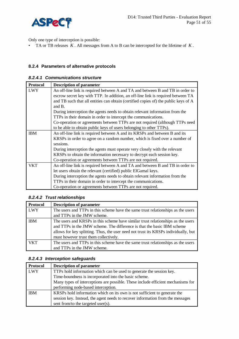
D14: Trusted Third Parties - Evaluation ReportPage 51 of 55
Only one type of interception is possible:• TA or TB releases K . All messages from A to B can be intercepted for the lifetime of K .
8.2.4 Parameters of alternative protocols
8.2.4.1 Communications structure
Protocol Description of parameterLWY An off-line link is required between A and TA and between B and TB in order to
escrow secret key with TTP. In addition, an off-line link is required between TAand TB such that all entities can obtain (certified copies of) the public keys of Aand B.During interception the agents needs to obtain relevant information from theTTPs in their domain in order to intercept the communications.Co-operation or agreements between TTPs are not required (although TTPs needto be able to obtain public keys of users belonging to other TTPs).
IBM An off-line link is required between A and its KRSPs and between B and itsKRSPs in order to agree on a random number, which is fixed over a number ofsessions.During interception the agents must operate very closely with the relevantKRSPs to obtain the information necessary to decrypt each session key.Co-operation or agreements between TTPs are not required.
VKT An off-line link is required between A and TA and between B and TB in order tolet users obtain the relevant (certified) public ElGamal keys.During interception the agents needs to obtain relevant information from theTTPs in their domain in order to intercept the communications.Co-operation or agreements between TTPs are not required.
8.2.4.2 Trust relationships
Protocol Description of parameterLWY The users and TTPs in this scheme have the same trust relationships as the users
and TTPs in the JMW scheme.IBM The users and KRSPs in this scheme have similar trust relationships as the users
and TTPs in the JMW scheme. The difference is that the basic IBM schemeallows for key splitting. Thus, the user need not trust its KRSPs individually, butmust however trust them collectively.
VKT The users and TTPs in this scheme have the same trust relationships as the usersand TTPs in the JMW scheme.
8.2.4.3 Interception safeguards
Protocol Description of parameterLWY TTPs hold information which can be used to generate the session key.
Time-boundness is incorporated into the basic scheme.Many types of interceptions are possible. These include efficient mechanisms forperforming node-based interception.
IBM KRSPs hold information which on its own is not sufficient to generate thesession key. Instead, the agent needs to recover information from the messagessent from/to the targeted user(s).

D14: Trusted Third Parties - Evaluation ReportPage 52 of 55
The scheme naturally incorporates key splitting, thus the agent may have toapproach more than one KRSP before being able to intercept the communication.Time-bounded interceptions are possible, but at the expense of a greatercomplexity of interception.Only one type of interception possible - KRSPs release information which can beused to help compute the session key. Thus, efficient node-based interceptionsare not possible.The receiver can check the correctness of the key recovery information.However, this process is more complex than VKT.
VKT TTPs hold information which on its own is not sufficient to generate the sessionkey. Instead, the agent needs to recover information from the messages sentfrom/to the targeted user(s).Key splitting is not featured in the basic scheme.Time-bounded interceptions are possible, but at the expense of a greatercomplexity of interception.Only one type of interception possible - TTPs release information which can beused to help compute the session key. Thus, efficient node-based interceptionsare not possible.The receiver can check the correctness of key recovery information.Before an interception, a third party can verify that key recovery information hasbeen correctly computed.
8.2.4.4 Escrow type
Protocol Description of parameterLWY Session key onlyIBM Session key onlyVKT Session key only
8.2.4.5 Cryptographic flexibility
Protocol Description of parameterLWY Session key is jointly generated by A, B, TA and TB.IBM Session key generated by user.
Flexible with regard to key recovery demands of different domains.Symmetric algorithm used to compute key recovery information can be differentin each domain.
VKT Session key generated by user.Flexible with regard to key recovery demands of different domains.
8.2.4.6 Communications type
Protocol Description of parameterLWY Two-way communication (thus no directional targeting).IBM Two-way communication (thus no directional targeting).VKT Two-way communication (thus no directional targeting).
8.2.4.7 Implementation
Protocol Description of parameterLWY No restrictions.IBM No restrictions.VKT ElGamal public key encryption used to compute key recovery information.

D14: Trusted Third Parties - Evaluation ReportPage 53 of 55
8.2.5 Evaluation of protocols against escrow requirements
8.2.5.1 LWY1. User completeness: Yes2. Agent completeness: Yes3. User soundness: The general problems that apply to all key escrow protocols exist (see section 0).4. Agent soundness: No. Although this is a difficult requirement to meet.5. User acceptability: No. Users do not have good flexibility over key management (changing their
secret and public keys is difficult). No built in mechanism for split escrow. However, communicationbetween TTPs not required.
6. Agent acceptability: Needs clarification of user soundness. Many types of interception are possible,including efficient means of performing node-based interceptions. TTPs can also generateinformation required for interception in advance, therefore interceptions do not necessarily requirecomputations to be performed by the TTP.
8.2.5.2 IBM1. User completeness: Yes2. Agent completeness: Yes3. User soundness: The general problems that apply to all key escrow protocols exist (see section 0).4. Agent soundness: No. Although this is a difficult requirement to meet.5. User acceptability: Yes. Users have good flexibility over key management (they can change their
session key), and cryptographic algorithms used. Split escrow can be catered for. Flexible withregard to key recovery demands of different domains. However, the initialisation stage is relativelycomplex.
6. Agent acceptability: Needs clarification of user soundness. Node based interceptions are inefficient.Agents may need to co-operate with many KRSPs. Computation required by KRSP in order torecover session key.
8.2.5.3 VKT1. User completeness: Yes2. Agent completeness: Yes3. User soundness: The general problems that apply to all key escrow protocols exist (see section 0).
However, a third party can detect that key recovery information has been correctly computed withoutactually performing key recovery. This may discourage abuse of the scheme.
4. Agent soundness: No. Although this is a difficult requirement to meet.5. User acceptability: Yes. User can change session key at any time. Split escrow can be catered for.
Flexible with regard to key recovery demands of different domains.6. Agent acceptability: Needs clarification of user soundness. Node-based interceptions are inefficient.
Computation required by TTP in order to recover session key. However, some abuse of the schemecan be detected without having to perform interception.
8.3 Appendix C: Protocol implemented in the first demonstratorThe following protocol, which is based on the protocol described in [JMW96a,JMW96b], isimplemented in the first demonstrator. The protocol is in the context of a pair of users, where one userwishes to send the other a confidential message and needs to be provided with a session key to protect it.The start situation for the first demonstrator is as follows.
1. Four participants, namely two users (one as a sender, say A, and the other as a receiver, say B)and two TTPs (one for each user, say TA and TB), are involved.

D14: Trusted Third Parties - Evaluation ReportPage 54 of 55
2. Two TTPs have agreed between them values g and p. These values must have the usualproperties required for operation of the Diffie-Hellman key exchange mechanism, namely that gmust be a primitive element modulo p, where p is a large prime and p-1 can be divided by anotherlarge prime q. These values have been passed to the two users.
3. Each TTP has an asymmetric signature verification key pair. The private signature key is knownonly to himself, and an authenticated copy of the public verification key can be accessed by hisown user and the other TTP.
4. Each user and his TTP have access to a protected channel between them, which provides originauthentication, data integrity and confidentiality.
Figure 8.3.11 shows the message exchanges of the protocol among the four participants. The protocolincludes four parts, each of which can optionally be run separately.
A TA TB B a tA tB b… … … … … … … … … … … … … … … … … … … … … … … … … … … … … …
M1 CertTA(gtA) → Part 1
M2 CertTB(gtB) ← … … … … … … … … … … … … … … … … … … … … … … … … … … … … … …
M3 B →
M4 CertTA(ga), a, gb Part 2
← … … … … … … … … … … … … … … … … … … … … … … … … … … … … … …
M5 CertTA(ga), gb, (optional eKAB(m))
→ Part 3
… … … … … … … … … … … … … … … … … … … … … … … … … … … … … …M6 CertTA(ga)
← M7 ga,b Part 4
→Figure 8.3.11 : The first demonstrator protocol
The following is the description of the protocol.Part 1: share a secret between two TTPs.
1. Each TTP, TA or TB, generates a private and public key agreement key pair (tA, gtA) or (tB, gtB).2. Each TTP sends his public key agreement key signed using his private signature key to the other
TTP in M1: CertTA(gtA) or in M2: CertTB(gtB).3. Each TTP verifies the received public key agreement key using an authenticated public signature
verification key of one another.4. Each TTP computes a shared secret, KTATB = gtAtB, using his own private key agreement key and
the other’s public key agreement key in Diffie-Hellman key establishment algorithm.Part 2: Certificate generation in A’s domain
1. A sends TA a request in M3 including B’s name.2. TA generates a random number a as A’s private send key and a corresponding public send key,
ga.3. TA makes a certificate for A’s public send key, CertTA(ga).

D14: Trusted Third Parties - Evaluation ReportPage 55 of 55
4. TA computes B’s private receive key, b = h(KTATB, B), and the corresponding public receive key,gb.
5. TA sends A’s public send key certificate, A’s private send key and B’s public receive key to A inM4.
6. A computes a shared key, KAB = gba, using his own private send key and B’s public receive key.Part 3: message transmission from A to B
A sends the following information to B in M5:• his public send key certificate issued by TA,• B’s public receive key, and• a optional message encrypted by the shared key, KAB.
Part 4: Certificate generation in B’s domain1. After receiving M5, B sends TB a request including A’s public send key certificate issued by TA,
and B's public receive key sent by A.2. TB computes B’s private receive key, b = h(KTATB, B), and verifies gb.3. TB verifies A's public send key certificate using the public signature verification key of TA.4. TB sends A’s public send key and B’s private receive key to B. Note that if B has already got his
current private receive key, this key does not need to be sent in M7.5. B computes the shared key, KAB = gab, using his own private receive key and A’s public send key.
After running the protocol successfully, a shared key KAB will be established between the sender andreceiver, and this key will be escrowed by both TTPs.