ts 102 687 - v1.1.1 - intelligent transport systems (its ... · etsi ts 102 687 v1.1.1 (2011-07)...
TRANSCRIPT
ETSI TS 102 687 V1.1.1 (2011-07)
Technical Specification
Intelligent Transport Systems (ITS);Decentralized Congestion Control Mechanisms for
Intelligent Transport Systems operating in the 5 GHz range;Access layer part

ETSI
ETSI TS 102 687 V1.1.1 (2011-07)2
Reference DTS/ITS-0040014
Keywords ITS, radio, transmission
ETSI
650 Route des Lucioles F-06921 Sophia Antipolis Cedex - FRANCE
Tel.: +33 4 92 94 42 00 Fax: +33 4 93 65 47 16
Siret N° 348 623 562 00017 - NAF 742 C
Association à but non lucratif enregistrée à la Sous-Préfecture de Grasse (06) N° 7803/88
Important notice
Individual copies of the present document can be downloaded from: http://www.etsi.org
The present document may be made available in more than one electronic version or in print. In any case of existing or perceived difference in contents between such versions, the reference version is the Portable Document Format (PDF).
In case of dispute, the reference shall be the printing on ETSI printers of the PDF version kept on a specific network drive within ETSI Secretariat.
Users of the present document should be aware that the document may be subject to revision or change of status. Information on the current status of this and other ETSI documents is available at
http://portal.etsi.org/tb/status/status.asp
If you find errors in the present document, please send your comment to one of the following services: http://portal.etsi.org/chaircor/ETSI_support.asp
Copyright Notification
No part may be reproduced except as authorized by written permission. The copyright and the foregoing restriction extend to reproduction in all media.
© European Telecommunications Standards Institute 2011.
All rights reserved.
DECTTM, PLUGTESTSTM, UMTSTM and the ETSI logo are Trade Marks of ETSI registered for the benefit of its Members. 3GPPTM and LTE™ are Trade Marks of ETSI registered for the benefit of its Members and
of the 3GPP Organizational Partners. GSM® and the GSM logo are Trade Marks registered and owned by the GSM Association.

ETSI
ETSI TS 102 687 V1.1.1 (2011-07)3
Contents
Intellectual Property Rights ................................................................................................................................ 5
Foreword ............................................................................................................................................................. 5
1 Scope ........................................................................................................................................................ 6
2 References ................................................................................................................................................ 6
2.1 Normative references ......................................................................................................................................... 6
2.2 Informative references ........................................................................................................................................ 7
3 Definitions, symbols and abbreviations ................................................................................................... 7
3.1 Definitions .......................................................................................................................................................... 7
3.2 Symbols .............................................................................................................................................................. 7
3.3 Abbreviations ..................................................................................................................................................... 8
4 Decentralized congestion control overview ............................................................................................. 8
4.1 DCC operational requirements ........................................................................................................................... 8
4.2 DCC architecture ................................................................................................................................................ 9
4.3 Network design limits (NDL) ............................................................................................................................. 9
4.4 DCC_access functional view ............................................................................................................................ 10
5 DCC access mechanisms ........................................................................................................................ 11
5.1 Transmit power control .................................................................................................................................... 11
5.1.1 TPC parameters .......................................................................................................................................... 11
5.1.2 TPC Operation ............................................................................................................................................ 12
5.2 Transmit rate control ........................................................................................................................................ 12
5.2.1 TRC parameters .......................................................................................................................................... 12
5.2.2 TRC Operation ............................................................................................................................................ 13
5.3 Transmit datarate control .................................................................................................................................. 13
5.3.1 TDC parameters .......................................................................................................................................... 13
5.3.2 TDC Operation ........................................................................................................................................... 14
5.4 DCC Sensitivity control ................................................................................................................................... 14
5.4.1 DSC parameters .......................................................................................................................................... 14
5.4.2 DSC operation ............................................................................................................................................ 15
5.5 Transmit access control .................................................................................................................................... 15
5.5.1 TAC parameters .......................................................................................................................................... 15
5.5.2 TAC operation ............................................................................................................................................ 15
5.6 DCC Transmit model ....................................................................................................................................... 16
5.7 DCC receive model .......................................................................................................................................... 16
5.7.1 Receive model parameters .......................................................................................................................... 16
5.7.2 Channel model ............................................................................................................................................ 17
5.7.3 Demodulation model................................................................................................................................... 17
5.7.4 Communication ranges ............................................................................................................................... 18
5.7.5 Example receive model ............................................................................................................................... 18
6 DCC_access components ....................................................................................................................... 19
6.1 DCC transmit queueing .................................................................................................................................... 19
6.2 Channel probing ............................................................................................................................................... 19
6.3 Transmit packet statistics ................................................................................................................................. 20
6.4 DCC access control loop .................................................................................................................................. 20
6.4.1 State machine .............................................................................................................................................. 20
6.4.2 State transitions ........................................................................................................................................... 21
6.4.3 State configuration ...................................................................................................................................... 22
6.4.4 State processing .......................................................................................................................................... 23
7 DCC access interfaces ............................................................................................................................ 25
7.1 Interface 1: IN-UNITDATA service ................................................................................................................ 25
7.2 Interface 2: MI-SET and MI-GET services ...................................................................................................... 25
Annex A (normative): DCC parameter .............................................................................................. 26

ETSI
ETSI TS 102 687 V1.1.1 (2011-07)4
A.1 Channel load measures ........................................................................................................................... 26
A.1.1 Parameters ........................................................................................................................................................ 26
A.1.2 Channel load ..................................................................................................................................................... 26
A.1.3 Load arrival rate ............................................................................................................................................... 26
A.1.4 Load average duration ...................................................................................................................................... 27
A.1.5 Receive packet arrival rate ............................................................................................................................... 27
A.1.6 Receive packet average duration ...................................................................................................................... 27
A.1.7 Packet Occupancy ............................................................................................................................................ 28
A.1.8 Channel busy time ............................................................................................................................................ 28
A.2 Transmit packet statistics ....................................................................................................................... 28
A.2.1 Transmit packet rate ......................................................................................................................................... 28
A.2.2 Transmit packet average duration..................................................................................................................... 29
A.2.3 Average transmit signal power ......................................................................................................................... 29
A.2.4 Transmit channel use ........................................................................................................................................ 29
A.3 Communication Ranges ......................................................................................................................... 30
A.3.1 Carrier Sense Range ......................................................................................................................................... 30
A.3.2 Estimated communication range ...................................................................................................................... 30
A.3.3 Estimated communication range under interference ........................................................................................ 30
A.4 Network Design Limits .......................................................................................................................... 31
A.4.1 NDL types and formats .................................................................................................................................... 31
A.4.2 NDL Input parameter and constants ................................................................................................................. 31
A.4.3 NDL database ................................................................................................................................................... 32
A.4.4 NDL output parameters .................................................................................................................................... 33
A.4.5 Channel dependent parameter .......................................................................................................................... 33
A.4.6 Priority dependent parameters .......................................................................................................................... 34
A.4.7 Basic control loop NDL database ..................................................................................................................... 34
A.4.8 Enhanced DCC algorithm NDL database ......................................................................................................... 35
Annex B (informative): Transmit power calibration .......................................................................... 36
B.1 Common principles of transmit power calibration ................................................................................. 36
B.2 Transmit power certification process for non modular ITS stations ...................................................... 36
B.2.1 Applicability and overview for non modular ITS stations ............................................................................... 36
B.2.2 Determination of antenna pattern for non modular ITS stations ...................................................................... 36
B.2.3 Measurement of e.i.r.p. for non modular ITS stations ...................................................................................... 37
B.3 Transmit power certification process for modular ITS stations ............................................................. 37
B.3.1 Applicability and overview for modular ITS stations ...................................................................................... 37
B.3.2 Determination of antenna pattern for modular ITS stations ............................................................................. 37
B.3.3 Determination of cable loss for modular ITS stations ...................................................................................... 37
B.3.4 Determination of output power level for modular ITS stations ........................................................................ 37
B.4 Specified e.i.r.p. levels and step requirements to be calibrated .............................................................. 38
Annex C (informative): Example of a DCC_Net algorithm................................................................ 39
C.1 Enhanced DCC algorithm ...................................................................................................................... 39
C.2 Remote information ................................................................................................................................ 40
Annex D (informative): Validation ....................................................................................................... 42
D.1 Validation scenarios ............................................................................................................................... 42
D.2 Validation performance criteria .............................................................................................................. 43
Annex E (informative): Bibliography ................................................................................................... 44
History .............................................................................................................................................................. 45

ETSI
ETSI TS 102 687 V1.1.1 (2011-07)5
Intellectual Property Rights IPRs essential or potentially essential to the present document may have been declared to ETSI. The information pertaining to these essential IPRs, if any, is publicly available for ETSI members and non-members, and can be found in ETSI SR 000 314: "Intellectual Property Rights (IPRs); Essential, or potentially Essential, IPRs notified to ETSI in respect of ETSI standards", which is available from the ETSI Secretariat. Latest updates are available on the ETSI Web server (http://ipr.etsi.org).
Pursuant to the ETSI IPR Policy, no investigation, including IPR searches, has been carried out by ETSI. No guarantee can be given as to the existence of other IPRs not referenced in ETSI SR 000 314 (or the updates on the ETSI Web server) which are, or may be, or may become, essential to the present document.
Foreword This Technical Specification (TS) has been produced by ETSI Technical Committee Intelligent Transport System (ITS).

ETSI
ETSI TS 102 687 V1.1.1 (2011-07)6
1 Scope ITS road safety and traffic efficiency systems include both vehicle to vehicle communications and related vehicle to roadside communication in highly dynamic vehicular ad hoc networks. These systems (ITS stations) are based on a set of protocols and parameters called ITS-G5 as specified in the European profile standard on the physical and medium access layer of 5 GHz ITS [2].
Many applications and services in ITS rely on the cooperative behavior of the vehicles and roadsides units which form a vehicular ad hoc network (VANET). The VANET enable the time critical road safety applications where fast information exchange is necessary to timely warn and support the driver. Special care should be taken to ensure proper functioning of the VANET and this includes decentralized congestion control (DCC) for the channels of ITS-G5.
DCC is a cross layer function, i.e. it has functions located on several layers of the ITS station reference architecture. Therefore the present document defines which DCC components are located on which layer of the ITS station communication architecture [5]. Furthermore the present document specifies the DCC mechanisms on the access layer (DCC_access) including transmit power control (TPC) per packet, transmit rate control (TRC) and transmit datarate control (TDC). The latter two control functions modify the average transmit power by modifying the duty cycle of the ITS station, i.e. the fraction of time that the ITS station is in "transmit" state. Additionally, DCC sensitivity control (DSC) adapts the clear channel assessment to resolve local channel congestion. Packets with higher priority are handled less restrictive introducing a transmit queueing concept and transmit access control (TAC).
The DCC mechanisms rely on knowledge about the channel. The channel state information is gained using channel probing. Channel probing measures are defined that enable the DCC methods TPC, TRC and TDC. The measures are on receive signal level thresholds or preamble information of detected packets.
The present document does not define the mechanisms at other layers than the access layer nor defines management aspects. These other mechanisms and the management aspects are necessary in order to make DCC work properly. The present document is primarily intended for trial use and may need to be updated after validation in field trials and/or other projects.
2 References References are either specific (identified by date of publication and/or edition number or version number) or non-specific. For specific references, only the cited version applies. For non-specific references, the latest version of the reference document (including any amendments) applies.
Referenced documents which are not found to be publicly available in the expected location might be found at http://docbox.etsi.org/Reference.
NOTE: While any hyperlinks included in this clause were valid at the time of publication ETSI cannot guarantee their long term validity.
2.1 Normative references The following referenced documents are necessary for the application of the present document.
[1] IEEE 802.11-2007: "IEEE Standard for Information technology - Telecommunications and information exchange between systems - Local and metropolitan area networks - Specific requirements - Part 11: Wireless LAN Medium Access Control (MAC) and Physical Layer (PHY) Specifications".
[2] ETSI ES 202 663: "Intelligent Transport Systems (ITS); European profile standard for the physical and medium access control layer of Intelligent Transport Systems operating in the 5 GHz frequency band".
[3] ETSI EN 302 571: "Intelligent Transport Systems (ITS); Radiocommunications equipment operating in the 5 855 MHz to 5 925 MHz frequency band; Harmonized EN covering the essential requirements of article 3.2 of the R&TTE Directive".

ETSI
ETSI TS 102 687 V1.1.1 (2011-07)7
[4] ETSI TS 102 868-1: "Intelligent Transport Systems (ITS); Testing; Conformance test specification for Co-operative Awareness Messages (CAM); Part 1: Test requirements and Protocol Implementation Conformance Statement (PICS) proforma".
[5] ETSI EN 302 665: "Intelligent Transport Systems (ITS); Communications Architecture".
[6] IEEE 802.2-1998: "Standard for Information technology -- Telecommunications and information exchange between systems -- Local and metropolitan area networks -- Specific requirements -- Part 2: Logical Link Control", (ISO/IEC 8802-2:1998).
2.2 Informative references The following referenced documents are not necessary for the application of the present document but they assist the user with regard to a particular subject area.
[i.1] ETSI TS 102 724: "Intelligent Transport Systems (ITS); Harmonized Channel Specifications for Intelligent Transport Systems operating in the 5 GHz frequency band".
[i.2] ETSI TS 102 723-3: "Intelligent Transport Systems; OSI cross-layer topics; Part 3: Interface between management entity and access layer".
[i.3] ETSI TS 102 723-10: "Intelligent Transport Systems; OSI cross-layer topics; Part 10: Interface between access layer and network and transport layers".
[i.4] ETSI TS 102 723-1: "Intelligent Transport Systems; OSI cross-layer topics; Part 1: Architecture and addressing schemes".
3 Definitions, symbols and abbreviations
3.1 Definitions For the purposes of the present document, the terms and definitions given in [1], [2], [3], [5] and the following apply:
DCC component: part of the DCC, located in one layer, e.g. DCC_access
DCC_access mechanism: functionality of DCC_access usually using several DCC_access components
NDL database: database that contains DCC_access configuration parameters, input parameters and output parameters
reference parameter: parameter controlled by a control loop
3.2 Symbols For the purposes of the present document, the symbols given in [1], [2], [3], [5] and the following apply:
acPrio access priority
NOTE: Provided by network layer or derived as specified in [1].
dB(x) decibel function: 10·log10(x) cl variable for channel load cs variable for carrier sense threshold ds variable for DCC sensitivity MIN(x1; …;xN) minimum function, returns its lowest argument minCL(Δt) minimum channel load for time time period Δt MAX(x1; …;xN) maximum function, returns its largest argument maxCL(Δt) maximum channel load for time time period Δt Mpkt measured number of packets Np number of probes

ETSI
ETSI TS 102 687 V1.1.1 (2011-07)8
NPR number of OFDM symbols in the preamble NDPMS data bits per OFDM symbol pow(p, x) exponentiation: xp
S signal power level Sth signal level threshold TAIR packet air time TCA average time for channel access Tm measuring interval Tp probing interval txQ number of DCC_access transmit queues
3.3 Abbreviations For the purposes of the present document, the abbreviations given in [1], [2], [3], [5] and the following apply:
DCC Decentralized Congestion Control DCC_access DCC component of the access layer DCC_app DCC component of the facility layer DCC_mgmt DCC component of the management layer DCC_net DCC component of the network layer D-CCA CCA sensitivity for DCC DPSK Digital Phase Shift Keying DSC DCC sensitivity control NDL Network Design Limits SM State Machine SNR Signal to Noise Ratio TAC Transmit Access Control TDC Transmit Datarate Control TPC Transmit Power Control TRC Transmit Rate Control VANET Vehicular Ad-hoc NETwork
4 Decentralized congestion control overview
4.1 DCC operational requirements "Decentralized congestion control" (DCC) is a mandatory component of ITS-G5 stations operating in ITS-G5A and ITS-G5B frequency bands to maintain network stability, throughput efficiency and fair resource allocation to ITS-G5 stations. DCC requires components on several layers of the protocol stack and these components jointly work together to fulfil the following operational requirements:
• Provide fair allocation of resources and fair channel access among all ITS stations in the same communication zone.
• Keep channel load caused by periodic messages below pre-defined thresholds.
• Reserve communication resources for the dissemination of event driven high priority messages.
• Provide fast adoption to a changing environment (busy / free radio channel).
• Keep oscillations in the control loops within well-defined limits.
• Comply to specific system requirements, e.g. reliability.

ETSI
ETSI TS 102 687 V1.1.1 (2011-07)9
4.2 DCC architecture The DCC architecture is displayed in Figure 1. It consists of the DCC components:
• DCC_access located in the access layer;
• DCC_net located in the networking and transport layer;
• DCC_app located in the facility layer;
• DCC_mgmt located in the management layer.
The components are connected through the DCC interfaces 1 to 5 as shown in Figure 1. These interfaces are mapped to the corresponding cross layer interfaces as described in TS 102 723 [i.2], [i.3], [i.4] and the present document.
Figure 1: DCC Architecture
The present document specifies DCC_access, which comprises the DCC mechanisms transmit power control (TPC), DCC sensitivity control (DSC), transmit rate control (TRC) transmit datarate control (TDC) and DCC access control (TAC)
Additionally DCC_access services are specified that are offered to other DCC components using interface 1 [i.3] and interface 2 [i.2]. These services are a transmit model (Clause 5.6), a receive model (Clause 5.7) and channel probing (Clause 6.2) and transmit packet statistics (Clause 6.3).
NOTE: The term packet is used on the access layer and the network layer to indicate that usually the same payload is transported.
4.3 Network design limits (NDL) An operational requirement of DCC is to keep the actual channel load below predefined limits that are part of the Network Design Limits (NDL, Clause A.4). The NDL are used to configure DCC_access. The NDL are stored in the NDL database that contains all relevant information used by DCC_access, i.e. configuration parameters, controlled parameters and DCC status information.
The NDL database is part of DCC_mgmt, i.e. the management layer is responsible for maintaining the information (configuration parameters). Data exchange between DCC_mgmt (including NDL database) and the other layers is described in the corresponding interface documents (TS 102 723 [i.2], [i.3], [i.4]).

ETSI
ETSI TS 102 687 V1.1.1 (2011-07)10
The NDL database includes:
• ranges of the controlled parameters (minimum and maximum values);
• design limits, i.e. default and target values of the controlled parameters;
• regulatory limits and device dependent parameters (e.g. max. transmit power);
• model parameters, e.g. parameters of the transmit model, channel model and receive model;
• internal control loop parameters, e.g. signal level thresholds and time constants.
The controlled parameters and the measured parameters are written to the NDL database, especially:
• reference values, i.e. the average target value used by DCC_access transmit queuing for per packet control;
• channel load measures.
4.4 DCC_access functional view Figure 2 shows the functional view of DCC_access with the building blocks:
• transmit queuing (Clause 6.1), which enhance the standard 802.11 queues by DCC mechanisms;
• channel probing (Clause 6.2) to collect statistics on the communication channel;
• transmit statistics (Clause 6.3) to observe the behavior of the own ITS station;
• control loop (Clause 6.4) that adapt the behavior of the own ITS station to the actual channel load.
Figure 2: DCC_access functional view
DCC_access relies on measured values for the channel load (Channel probing) and on statistics about transmitted packets (Transmit statistics).
The transmit statistics of DCC_access shall take into account all packets that are transmitted, including packet repetitions, RTS, CTS and ACK packets.
The Control loop manages reference parameters according to the DCC_access mechanisms TPC, TRC, TDC and DSC. The reference parameters are:
• TPC → reference transmit power: NDL_refTxPower
• TRC → reference packet interval: NDL_refPacketInterval

ETSI
ETSI TS 102 687 V1.1.1 (2011-07)11
• TDC → reference datarate: NDL_refDatarate
• DSC → reference D-CCA sensitivity: NDL_refCarrierSense
• TAC → reference queue status NDL_refQueue
Their usage is specified in Clause 5.
Packets are classified at network layer, which provides the access priority (acPrio) per packet via interface 1 (see Figure 1). Additionally each packet that arrives from the network layer has a preset value of transmit power and datarate.
The block Transmit queuing in Figure 2 assigns the packets to the corresponding MAC transmit queue (see [1]).
Enqueuing a packet to the MAC transmit queue shall not occur more frequently than specified by TRC.
On enqueuing a packet to its MAC transmit queue the preset values are compared with the current reference values of TPC, TRC and TDC and modified if necessary (see Clause [4]).
The DSC reference parameter NDL_refCarrierSense is used to control the CCA (see [1]).
DCC_app and DCC_net are out of scope of the present document. They may affect DCC_access indirectly by dynamically modifying the NDL database (Clause 4.3), i.e. the control loop configuration parameters. DCC_access provides a set of status parameters to these upper layers via the NDL database.
5 DCC access mechanisms
5.1 Transmit power control
5.1.1 TPC parameters
"Transmit power control" (TPC) is based on transmit power thresholds listed in Table 1.
The signal power thresholds depend on the selected channel from ITS-G5A or ITS-G5B and the selected transmit queue.
These thresholds are part of the NDL and shall be maintained by DCC_mgmt (Clause 4.2).
All transmit signal power thresholds shall be of type ndlType_txPower as specified in Table A.1.
Table 1: Transmit power thresholds
Transmit power thresholds Definition
NDL_minTxPower minimum transmit power (e.i.r.p.) NDL_maxTxPower maximum transmit power (e.i.r.p.) NDL_defTxPower(acPrio) default transmit power (e.i.r.p.) NDL_refTxPower(acPrio) reference transmit power (e.i.r.p.)
NDL_minTxPower is the minimum transmit signal power that can be selected by DCC_access.
NDL_maxTxPower is the maximum transmit signal power that can be selected by DCC_access, considering the maximum possible power and the maximum power allowed by regulation. Thus this value depends on the selected channel.
NDL_defTxPower is the default value for NDL_refTxPower, i.e. the transmit power that is used if no preset value is available.
NDL_refTxPower is the reference parameter set by the DCC_access mechanism TPC.

ETSI
ETSI TS 102 687 V1.1.1 (2011-07)12
The NDL transmit signal power thresholds shall fulfil the following relations:
EQ 1: NDL_minTxPower ≤ NDL_refTxPower ≤ NDL_maxTxPower
EQ 2: NDL_minTxPower ≤ NDL_defTxPower ≤ NDL_maxTxPower
5.1.2 TPC Operation
The transmit power (effTxPower) of a packet can be set per-MSDU as described in [2]. This presetting of the network layer is modified by TPC according to the following rules:
• On reception via DCC interface 1 the packet is assigned to the corresponding transmit queue defined by the per-MSDU priority (acPrio).
• The preset per-MSDU value of effTxPower is corrected according to the following relation:
EQ 3: effTxPower = MIN(NDL_refTxPower(acPrio), effTxPower)
5.2 Transmit rate control
5.2.1 TRC parameters
"Transmit Rate Control" (TRC) is based on packet timing thresholds listed in Table 2.
The packet timing thresholds depend on the selected channel from ITS-G5A or ITS-G5B and the selected transmit queue. Timing thresholds are divided into packet duration thresholds and packet interval thresholds.
Packet duration thresholds shall be of type ndlType_packetDuration as specified in Table A.1. Packet interval thresholds shall be of type ndlType_packetInterval as specified in Table A.1. The thresholds are part of the NDL and shall be maintained by DCC_mgmt (Clause 4.2).
Table 2: Packet timing thresholds
Packet timing thresholds Definition Packet duration thresholds NDL_maxPacketDuration(acPrio) maximum duration (air time) of a packet Packet interval thresholds NDL_minPacketInterval minimum interval between packets NDL_maxPacketInterval maximum interval between packets NDL_defPacketInterval(acPrio) default interval between packets NDL_refPacketInterval(acPrio) reference interval between packets
NDL_maxPacketDuration is the maximum allowed air time of a packet (TAIR). TAIR is derived from the preamble duration and the number of data bits per OFDM symbol NDBPS (see note 1):
EQ 4: NPR= (TPREAMBLE+TSIGNAL) / TSYMBOL
EQ 5: TAIR = (NPR+ NSYMBOL)*TSYMBOL
with TPREAMBLE, TSIGNAL, TSYMBOL and NSYMBOL as specified in [1].
NOTE 1: NSYMBOL≈8*packetLength/NDBPS with packetLength as the number of bytes of the packet as encoded in the SIGNAL field of the PPDU (see [1]). NDPSK is the number of data bits in an OFDM symbol dependent on MCS.
NOTE 2: NPR = 5
NOTE 3: TSYMBOL = 8 μs for 10 MHz channels.
NDL_maxPacketDuration shall be of type ndlType_packetDuration as specified in Table A.1.
NDL_minPacketInterval is the minimum packet interval that can be selected by DCC_access.

ETSI
ETSI TS 102 687 V1.1.1 (2011-07)13
NDL_maxPacketInterval is the maximum packet interval that can be selected by DCC_access.
NDL_defPacketInterval is the default value for NDL_refPacketInterval, i.e. the packet interval that is used if TRC is inactive.
NDL_refPacketInterval is the reference parameter set by the DCC_access mechanism TRC.
The packet timing thresholds shall fulfil the following relations:
EQ 6: NDL_minPacketInterval ≤ NDL_refPacketInterval ≤ NDL_maxPacketInterval
EQ 7: NDL_minPacketInterval ≤ NDL_defPacketInterval ≤ NDL_maxPacketInterval
The packet intervals shall be measured between subsequent starts of packets.
NDL_maxPacketDuration shall be small compared to NDL_minPacketInterval (see [i.1]).
The packet intervals are of type ndlType_packetInterval as specified in Table A.1.
5.2.2 TRC Operation
The packet air time of a packet (TAIR) is derived from the packet length according Clause 5.2.1.
• On reception via DCC Interface 1 the packet is assigned to the corresponding transmit queue defined by the per-MSDU priority (acPrio).
• In case that TAIR exceeds NDL_maxPacketDuration the packet shall be dropped.
NOTE 1: TDC could be used to decrease TAIR and avoid packet drops (Clause 5.3.2).
• If NDL_refPacketInterval(acPrio) > 0 the configured packet interval shall be ensured.
Ensuring the packet interval means that there shall be a time interval of at least NDL_refPacketInterval(acPrio) between the transmission start of the current packet (from queue acPrio) and the transmission start of the previous packet.
NOTE 2: Transmissions of the previous packet also includes packet repetitions, RTS, CTS or ACK packets.
NOTE 3: The time for arbitration can be neglected.
5.3 Transmit datarate control
5.3.1 TDC parameters
"Transmit Datarate Control" (TDC) is based on datarate thresholds listed in Table 3.
The datarate thresholds depend on the selected channel from ITS-G5A or ITS-G5B and the selected priority.
All datarate thresholds shall be of type ndlType_dataRate as specified in Table A.1. They shall be maintained by DCC_mgmt (Clause 4.2).
Table 3: Packet datarate thresholds
Packet datarate thresholds Definition NDL_minDatarate minimum datarate NDL_maxDatarate maximum datarate NDL_defDatarate(acPrio) default datarate NDL_refDatarate(acPrio) reference datarate
NDL_minDatarate is the minimum datarate that can be selected by DCC_access.
NDL_maxDatarate is the maximum datarate that can be selected by DCC_access.

ETSI
ETSI TS 102 687 V1.1.1 (2011-07)14
NDL_defDatarate is the default value of NDL_refDatarate, i.e. the value that is used if TDC is inactive.
NDL_refDatarate is the reference parameter set by the DCC_access mechanism TDC.
The datarate parameters are specified via the MCS value as specified in [2].
The datarate parameters shall fulfil the following relations:
EQ 8: NDL_minDatarate ≤ NDL_refDatarate ≤ NDL_maxDatarate
EQ 9: NDL_minDatarate ≤ NDL_defDatarate ≤ NDL_maxDatarate
5.3.2 TDC Operation
The transmit datarate (effTxDatarate) of a packet can be set on a per-MSDU basis as described in [2]. This reference setting is modified by DCC_access according the following rules:
• On reception via Interface 1 the packet is assigned to the corresponding transmit queue defined by the per-MSDU priority (acPrio).
• The preset per-MSDU value effTxDatarate is corrected according to the following relation:
EQ 10: effTxDatarate = MAX(NDL_refDatarate(acPrio), effTxDatarate)
Furthermore the following TDC functionality shall be provided
• While the air time TAIR of a packet exceeds NDL_maxPacketDuration the datarate effTxDatarate shall be increased, but not above NDL_maxDatarate.
5.4 DCC Sensitivity control
5.4.1 DSC parameters
"DCC Sensitivity Control" DSC is based on sensitivity thresholds listed in Table 4. All sensitivity thresholds shall be of type ndlType_rxPower as specified in Table A.1. They shall be maintained by DCC_mgmt (Clause 4.2).
The sensitivity thresholds are used to determine whether the transmitter is clear to send or not (Table 4). They depend on the selected channel from ITS-G5A or ITS-G5B (see [i.1]).
Table 4: DCC sensitivity thresholds
Receive signal thresholds Definition NDL_minCarrierSense minimum D-CCA sensitivity NDL_maxCarrierSense maximum D-CCA sensitivity for DCC NDL_defCarrierSense default D-CCA sensitivity NDL_refCarrierSense reference D-CCA sensitivity
The "Clear Channel Assessment for DCC" (D-CCA) shall indicate a busy channel during a reception of a packet with receive level greater than NDL_refCarrierSense. In case that the preamble portion was missed, the D-CCA shall hold the carrier sense signal busy for any signal above NDL_refCarrierSense.
NDL_minCarrierSense is the minimum D-CCA sensitivity that can be selected by DCC_access.
NDL_maxCarrierSense is the maximum D-CCA sensitivity that can be selected by DCC_access.
NDL_defCarrierSense is the default value of NDL_refCarrierSense, i.e. the value that is used if DSC is inactive.
NDL_refCarrierSense is the reference parameter set by DCC_access mechanism DSC.
The thresholds for D-CCA sensitivity shall fulfil the following relations:
EQ 11: NDL_ minCarrierSense ≤ NDL_refCarrierSense ≤ NDL_maxCarrierSense

ETSI
ETSI TS 102 687 V1.1.1 (2011-07)15
5.4.2 DSC operation
DSC has an impact on CCA by applying the reference parameters NDL_refCarrierSense instead of the installed receiver sensitivity and the -65 dBm carrier sense threshold defined in [1]. This modified version of CCA is called D-CCA.
NOTE 1: The receiver sensitivity is not modified, only the thresholds for CCA. This provides the same chance for channel access to ITS stations with high sensitive receivers. The transmitter is allowed to transmit although a far distant transmitter might be active at the same time.
Whenever the DCC_acces control loop changes its state (Clause 6.4.2) the D-CCA reference parameter NDL_refCarrierSense is modified accordingly (Clause 6.4.4).
NOTE 2: DSC gives priority in channel access to higher priority messages by setting a higher D-CCA sensitivity threshold NDL_refCarrierSense for the "priority" transmit queues and DCC prevents channel congestion resulting from external interference blocking the transmitter due to a too sensitive carrier sensing.
5.5 Transmit access control
5.5.1 TAC parameters
"Transmit access control" (TAC) is the DCC_access mechanism that support the operational requirement of fair channel access. In case of high channel load the TAC is more restrictive to ITS-stations that transmit many packets. This is done using the DCC_access transmit queueing (Clause 6.1).
The DCC_mgmt shall maintain the queueing parameters as shown in Table 6 (Clause 4.2). The parameters shall be maintained per channel.
Table 5: Queueing parameters
Receive signal thresholds Definition NDL_numQueue Number of transmit queues in DCC_access NDL_refQueueStatus(acPrio) Status of transmit queue
NDL_numQueue is the number of available transmit queues (Clause 6.1).
NDL_refQueueStatus(acPrio) is the reference parameter set by the DCC_access mechanism TAC. It is an array of length NDL_numQueue. An array element NDL_refQueueStatus(acPrio) indicates the status of the transmit queue with priority acPrio.
5.5.2 TAC operation
The transmit queues are ordered according the priority such that the highest priority queue has priority index q = 0. The actual transmit statistics (A.2) are compared with the statistics of the DCC transmit model (Clause 5.6).
If too many packets are sent with priority index less or equal q the corresponding queue is marked as closed, i.e.:
EQ 12: NDL_refQueueStatus(q) = CLOSED if txChannelUse(q) ≥ NDL_tmChannelUse(q)
otherwise the queue is OPEN, i.e.:
EQ 13: NDL_refQueueStatus(q) = OPEN if txChannelUse(q) < NDL_tmChannelUse(q)
Packets with priority acPrio that arrives at a closed transmit queue (NDL_refQueueStatus(acPrio) = CLOSED) shall be dropped.
NOTE: Packet drops can be avoided by the network layer by checking the queue status before sending a packet to the access layer.

ETSI
ETSI TS 102 687 V1.1.1 (2011-07)16
The time interval between subsequent checks of the rules above shall be not greater than NDL_minDccSampling (Table 14).
5.6 DCC Transmit model DCC_access relies on a transmit model that approximates the expected channel use of an ITS station. DCC_access compares the statistics of the own transmissions with the transmit model.
The DCC_mgmt shall maintain the transmit model parameters as shown in Table 6 (Clause 4.2). The parameters shall be maintained per channel.
Table 6: Transmit model parameters
Transmit model parameters Definition NDL_tmPacketArrivalRate(acPrio) expected transmit packet arrival rate NDL_tmPacketAvgDuration(acPrio) expected average transmit packet duration NDL_tmPacketAvgPower(acPrio) expected average transmit power NDL_tmChannelUse(acPrio) expected cumulative channel use NDL_maxChannelUse maximum channel use
NDL_tmPacketArrivalRate(acPrio) is specified as the expected arrival rate of all packets transmitted by the ITS-station with priority acPrio.
EXAMPLE: NDL_tmPacketArrivalRate(AC_BE) = 3 packet/s means that not more than 3 packets/s are expected with priority AC_BE.
NDL_tmPacketAvgDuration(acPrio) is specified as the expected average duration of all packets transmitted with priority acPrio.
NDL_tmPacketAvgPower(acPrio) is specified as the expected average signal power of all packets arriving from the network layer with priority acPrio, considering the preset per-MSDU values effTxPower (Clause 5.1.2) and effTxDatarate (Clause 5.3.2).
The cumulative transmit channel use NDL_tmChannelUse(acPrio) is specified as the fraction of time that the ITS station is expected to use the channel by transmitting packets with priority less or equal acPrio. It is derived from the expected transmit packet arrival rate and the expected average duration.
EQ 14 NDL_tmChannelUse(acPrio) = ∑n=0…acPrio NDL_tmPacketAvgDuration(n) * NDL_tmPacketArrivalRate(n)
The channel use parameters shall be of type ndlType_channelUse as specified in Table A.1.
NOTE: NDL_tmChannelUse(acPrio) could be used as reference parameter by other DCC components, e.g. DCC_net.
NDL_maxChannelUse is the overall channel use with
EQ 15 NDL_maxChannelUse = NDL_tmChannelUse(NDL_numQueue-1)
5.7 DCC receive model The mechanisms of DCC_access rely on a receive model that is used to estimate the communication range. This receive model is based on a demodulation model and a channel model.
5.7.1 Receive model parameters
The DCC_mgmt shall maintain the receive model parameters as shown in Table 7.

ETSI
ETSI TS 102 687 V1.1.1 (2011-07)17
Table 7: Receive model parameters
Receive model parameter Definition NDL_defDccSensitivity Default DCC receiver sensitivity NDL_maxCsRange Maximum carrier sensing range NDL_refPathloss Reference pathloss parameter NDL_minSNR Minimum SNR to decode 3 Mbit/s datarate
These parameters are used in the demodulation model (Clause 5.7.3) and the channel model (Clause 5.7.2).
NDL_defDccSensitivity is the default receiver sensitivity that DCC_access assumes for other ITS stations. It shall be of type ndlType_rxPower as specified in Table A.1.
NDL_maxCsRange is the maximum carrier sensing range that results for the 3 Mbit/s datarate assuming that a packet can be decoded at a signal to noise ratio NDL_minSNR whereas the receive signal strength equals NDL_defDccSensitivity and the transmit signal power equals NDL_maxTxPower.
NDL_refPathloss is the pathloss parameter of the pathloss channel model (Clause 5.7.2) for which the following relation shall hold:
EQ 16: 1,8 ≤ NDL_refPathloss ≤ 4,0
NDL_refPathloss shall be of type ndlType_pathloss as specified in Table A.1.
NDL_minSNR is the expected SNR at which other ITS stations can successfully decode the 3 Mbit/s datarate.
NDL_minSNR shall be of type ndlType_snr as specified in Table A.1.
5.7.2 Channel model
DCC_access shall estimate the communication range for line-of-sight communication. The estimates shall be made available to the management entity (Clause 5.7.4).
This estimation relies on the log-distance path loss model given in EQ 17 and EQ 18. The channel model links the distance between transmitter and receiver to a receive signal power rxPower given a transmit power txPower with the following properties:
EQ 17: rxPower(distance/2) = rxPower(distance) + 3 dB * NDL_refPathloss
EQ 18: rxPower(NDL_maxCsRange) = NDL_defDccSensitivity + (txPower− NDL_maxTxPower)
EQ 17 establishes a linear behavior of the receive signal power (in decibel) when displayed on an logarithmic distance axis (Figure 3). EQ 18 gives a fixed-point as a result of the specification of NDL_maxCsRange in Clause 5.7.1.
NOTE: NDL_refPathloss=2 gives the free space channel model.
5.7.3 Demodulation model
DCC_access relies on a demodulation model. The SNR demodulation model is based on the assumption that the demodulation and decoding process is successful if the actual SNR is above a given threshold requiredSnr(datarate). The detection process is assumed to be successful if the actual SNR is at least NDL_minSNR.
On request DCC_access shall provide the required SNR requiredSnr(datarate) dependent on the datarate:
EQ 19: requiredSnr(datarate) = NDL_minSNR + NDL_snrBackoff(datarate)
with NDL_snrBackoff(datarate) as given in Table 8.
All SNR values shall be encoded with type ndlType_snr as specified in Table A.1.

ETSI
ETSI TS 102 687 V1.1.1 (2011-07)18
Table 8: SNR backoff
MCS Datarate (Mbit/s)
ΔSNR (dB)
0 3 0 1 4,5 1 2 6 3 3 9 5 4 12 8 5 18 12 6 24 16 7 27 17
NOTE 1: Table 8 is derived from the minimum receiver sensitivity as specified in [1].
NOTE 2: MCS according Table 3 of [2].
5.7.4 Communication ranges
On request DCC_access shall provide the communication ranges as summarized in Table 9 to the management entity.
Table 9: Communication ranges
Communication ranges carrierSenseRange (txPower)
estCommRange(txPower, datarate) estCommRangeIntf(txPower, datarate)
The communication ranges depend on the input parameters txPower and the datarate.
The specification of the communication ranges is given in Clause A.3.
All communication ranges shall be of type ndlType_distance as specified in Table A.1.
5.7.5 Example receive model
Figure 3 shows an example of the receive model. In this example it is assumed that the noise level (-95 dBm) is by NDL_minSNR = 10 dB smaller than the NDL_defDccSensitivity level (-85 dBm). In case the packet is transmitted at 3 Mbit/s with the maximum transmit power NDL_maxTxPower, it can be successfully decoded at a distance of NDL_maxCsRange = 1 000 m.
In the same scenario, the successful decoding of a packet transmitted at a datarate of 12 Mbit/s requires a SNR that is by ΔSNR(12 Mbit/s) = 8 dB higher than the one for the packet transmitted at 3 Mbit/s. The corresponding distance reduces to less than 500 m.

ETSI
ETSI TS 102 687 V1.1.1 (2011-07)19
Figure 3: Example receive model
6 DCC_access components
6.1 DCC transmit queueing ITS-G5 shall use the EDCA mechanism per channel defined in [1]. DCC transmit queuing shall support one transmit queue per EDCA queue. The EDCA parameters (AIFS, CWmin, CWmax and TXOP) shall be set as specified in [1] on a per-queue basis.
Additionally to the standard EDCA mechanisms in [1] the DCC_access transmit queuing shall meet the DCC_access transceiver requirements for TPC, TRC and TDC (Clause 5). The following additional parameters are used to define the characteristic of each queue.
Table 10: DCC transmit queuing parameter
Channel load thresholds Definition NDL_refTxPower(acPrio) Reference transmit power per queue (implements TPC) NDL_refPacketInterval(acPrio) Reference frame rate per queue (implements TRC) NDL_refDatarate(acPrio) Reference frame datarate per queue (implements TDC) NDL_refCarrierSense(acPrio) Reference threshold for D-CCA (implements DSC) NDL_queueLen(acPrio) Maximum count of pending frames
NOTE: According to [1] at least 4 transmit queues are available (AC_VI, AC_VO, AC_BE and AC_BK), but typical WLAN controllers implement up to 10 transmit queues.
6.2 Channel probing DCC relies on channel probing, i.e. the extraction of channel load measures from the received signal and detected packets (PLCP header).
DCC_access shall provide the channel load measures as listed in Table 10 as a service (Clause 4.2). The channel load measures are specified in Clause A.1.

ETSI
ETSI TS 102 687 V1.1.1 (2011-07)20
Table 11: Channel load measures
Channel load measure channelLoad(ds)
loadArrivalRate(ds) loadAvgDuration(ds) packetArrivalRate(ds) packetAvgDuration(ds) channelBusyTime(ds, cs)
The channel load measures depend on the DCC sensitivity ds and the carrier sense threshold cs. Although the channel load measures are defined for all values of ds and cs, only the following settings are mandatory:
ds = cs = NDL_defCarrierSense
NOTE: The default value NDL_defCarrierSense is not changed. Therefore the channel load measurements are independent of the adaptation by the DCC control loop.
Channel probing shall use the threshold NDL_defCarrierSense (Clause A.1.2).
D-CCA (Clause 5.4.2) shall use NDL_refCarrierSense
The DCC_access methods TPC, TRC and TDC rely on the channel load measures channelLoad(ds) or channelBusyTime(ds, cs). The other measures are provided to other DCC components as a service (Clause 4.2).
6.3 Transmit packet statistics DCC relies on packet statistics, i.e. how often packets are transmitted by the ITS station of a given priority. All transmitted packets are taken into account including system generated packets like RTS, CTS, ACK and packet repetitions.
DCC_access shall provide the transmit packet statistics as a service (Clause 4.2). The transmit packet statistics are summarized in Table 12 and specified in Clause A.2.
Table 12: Transmit packet statistics
Transmit packet statistics Definition txPacketArrivalRate(acPrio) transmit packet arrival rate txPacketAvgDuration(acPrio) transmit packet average duration txSignalAvgPower(acPrio) transmit signal average power txChannelUse(acPrio) cumulative transmit channel use
The transmit model parameter tmChannelUse(acPrio) as specified in Table 6 serve as thresholds for the actual channel use txChannelUse(acPrio).
RTS, CTS and ACK shall be accounted with the highest priority (AC_VI) and packet repetitions shall be accounted with the same priority as the original packet.
6.4 DCC access control loop
6.4.1 State machine
The DCC_access control loop is the central element of DCC_access. It distinguishes three states RELAXED, RESTRICTIVE and ACTIVE building a "state-machine" (SM) as displayed in, Figure 4.

ETSI
ETSI TS 102 687 V1.1.1 (2011-07)21
RELAXED RESTRICTIVEACTIVE
Figure 4: DCC_access state machine
The SM relies on channel load threshods as listed Table 13. The DCC_mgmt shall maintain the channel load thresholds for the selected channel from ITS-G5A or ITS-G5B.
Table 13: State machine parameters
Channel load thresholds Definition NDL_minChannelLoad relaxed channel load NDL_maxChannelLoad restrictive channel load
The channel load channelLoad(ds) is specified as the fraction of time that the received signal level is above ds (Clause A.1). The objective of DCC_access is to keep the channel load below NDL_maxChannelLoad, i.e.
EQ 20: channelLoad(NDL_defDccSensitivity) ≤ NDL_maxChannelLoad
The NDL channel load thresholds shall fulfil the following relation:
EQ 21: NDL_minChannelLoad ≤ NDL_maxChannelLoad
NDL_minChannelLoad is the minimum channel load below which the channel is assumed to be mainly free and DCC_access will be in state RELAXED.
NDL_maxChannelLoad is the maximum channel load above which the channel is assumed to be overloaded and DCC_access will be in state RESTRICTIVE.
The state changes are triggered if the measured channel load exceeds given thresholds for a period of time. The DCC_mgmt shall maintain the state machine time constants (Table 14) for the selected channel from ITS-G5A or ITS-G5B.
Table 14: State machine time constants
State machine time constants NDL_TimeUp Time constant ramping up (more restrictive) NDL_TimeDown Time constant ramping down (less restrictive) NDL_minDccSampling sampling time of the DCC_access SM
Two time constants NDL_TimeUp and NDL_TimeDown control how fast the SM react on changes of the channel load.
NDL_TimeUp controls how fast the control loop reacts if the channel load is increased.
NDL_TimeDown controls how fast the control loop reacts if the channel load is decreased.
NDL_minDccSampling is the minimum time interval between subsequent checks for SM transitions (Clause 6.4.2)
The state machine time constants shall fulfil the following relation:
EQ 22: NDL_minDccSampling ≤ NDL_timeUp ≤ NDL_timeDown
6.4.2 State transitions
The state transitions of the SM shall be based on two input signals:
• minCL(NDL_timeUp) Minimum channel load for the past time period of length NDL_timeUp
ETSI
ETSI TS 102 687 V1.1.1 (2011-07)22
• maxCL minCL(NDL_timeDown). Maximum channel load for the past time period of length NDL_timeDown
The channel load measure channelLoad(NDL_defCarrierSense) shall be used to determine minCL(NDL_timeUp) and maxCL (NDL_timeDown).
The initial state shall be the state RELAXED.
The state transitions of the SM shall be event driven according the following rules:
In state RELAXED:
• the state shall be switched to ACTIVE if clMin(NDL_timeUp) ≥ NDL_minChannelLoad.
In state RESTRICTIVE:
• the state shall be switched to ACTIVE if clMax(NDL_timeDown) < NDL_maxChannelLoad.
In state ACTIVE:
• the state shall be switched to RELAXED if clMax(NDL_timeDowm) < NDL_minChannelLoad.
• the state shall be switched to RESTRICTIVE if clMin(NDL_timeUp) ≥ NDL_maxChannelLoad.
The time interval between subsequent checks of the rules above shall be not greater than NDL_minDccSampling.
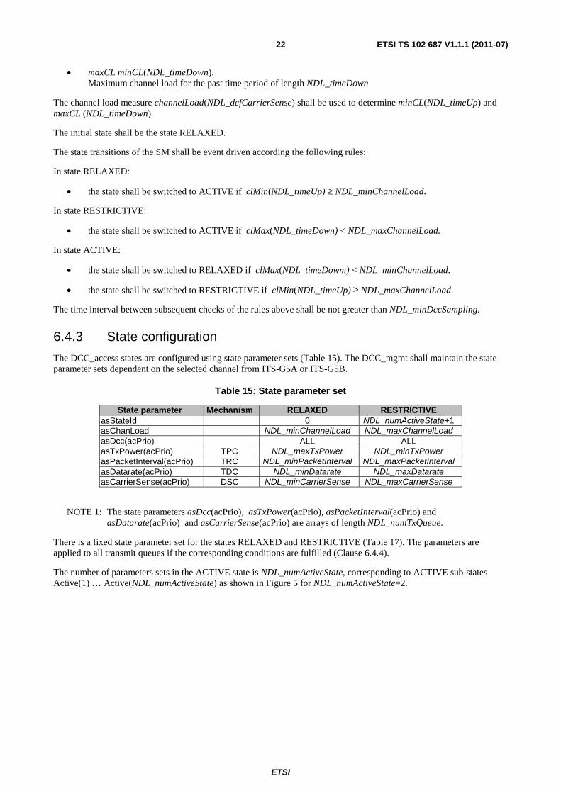
6.4.3 State configuration
The DCC_access states are configured using state parameter sets (Table 15). The DCC_mgmt shall maintain the state parameter sets dependent on the selected channel from ITS-G5A or ITS-G5B.
Table 15: State parameter set
State parameter Mechanism RELAXED RESTRICTIVE asStateId 0 NDL_numActiveState+1 asChanLoad NDL_minChannelLoad NDL_maxChannelLoad asDcc(acPrio) ALL ALL asTxPower(acPrio) TPC NDL_maxTxPower NDL_minTxPower asPacketInterval(acPrio) TRC NDL_minPacketInterval NDL_maxPacketInterval asDatarate(acPrio) TDC NDL_minDatarate NDL_maxDatarate asCarrierSense(acPrio) DSC NDL_minCarrierSense NDL_maxCarrierSense
NOTE 1: The state parameters asDcc(acPrio), asTxPower(acPrio), asPacketInterval(acPrio) and asDatarate(acPrio) and asCarrierSense(acPrio) are arrays of length NDL_numTxQueue.
There is a fixed state parameter set for the states RELAXED and RESTRICTIVE (Table 17). The parameters are applied to all transmit queues if the corresponding conditions are fulfilled (Clause 6.4.4).
The number of parameters sets in the ACTIVE state is NDL_numActiveState, corresponding to ACTIVE sub-states Active(1) … Active(NDL_numActiveState) as shown in Figure 5 for NDL_numActiveState=2.

ETSI
ETSI TS 102 687 V1.1.1 (2011-07)23
RELAXED Active(2)Active(1) RESTRICTIVE
ACTIVE
increasing channel load
Figure 5: ACTIVE sub-states (NDL_numActiveState=2)
NOTE 2: The ACTIVE sub-states are fully meshed. The current sub-state depends on the channel load history. Nevertheless if the channel load changes slowly the list index n increases and decreases accordingly.
The DCC_mgmt shall maintain the number of ACTIVE sub-states and the current state of the SM as listed in Table 16.
Table 16: SM status parameter
DCC parameters Definition NDL_numActiveState number of ACTIVE sub-states NDL_curActiveState current state
The configuration of the ACTIVE sub-states describes the DCC_access mechanisms TPC, TRC, TDC and DSC.
All parameter sets are collected in a state list stateList with list index asStateId. The parameter set of the state RELAXED is stateList(0). The parameter set the of state RESTRICTIVE is stateList(NDL_numActiveState+1). The parameter sets of the ACTIVE sub-states have list indices NDL_asStateId ∈ {1… NDL_numActiveState}.
The state list stateList shall form an ordered list with respect to the channel load parameter NDL_asChanLoad, i.e.:
EQ 23 NDL_asChanLoad(n−1) < NDL_asChanLoad(n) for n ∈ {1; 2; … ; NDL_numActiveState+1}
Hereby NDL_asChanLoad(n) is the parameter NDL_asChanLoad of the parameter set stateList(n), i.e. the argument n is the sub-state selector.
The state parameters asDcc(acPrio), asTxPower(acPrio), asPacketInterval(acPrio), asDatarate(acPrio) and asCarrierSense(acPrio) are arrays of length NDL_numTxQueue.
The parameter asDcc of type ndlType_dccMechanism (Table A.2) is used to select which DCC_access mechanisms are selected (Table A.2).
6.4.4 State processing
When a state is entered the state output parameters are set as listed in Table 17. The state output parameters are in a set of the same type as the configured state parameter sets of Table 15. This enables the assignment of a state parameter set to the state output parameters.

ETSI
ETSI TS 102 687 V1.1.1 (2011-07)24
Table 17: State output parameters
State output parameter Definition NDL_refStateId State identifier NDL_refChannelLoad applied channel load threshold NDL_refDcc applied DCC_access mechanism NDL_refTxPower applied TPC parameter NDL_refPacketInterval applied TRC parameter NDL_refDatarate applied TDC parameter NDL_refCarrierSense applied DSC parameter
When a state change occur the following state output parameters shall be set:
In state RELAXED:
• Set the state output parameters to the RELAXED parameter set of Table 15.
In state RESTRICTIVE:
• Set the state output parameters to the RESTRICTIVE parameter set of Table 15.
In state ACTIVE:
• Find asStateId = MAX(stateUp, stateDown) with:
EQ 24 minCL(NDL_timeUp) ≥ NDL_asChanLoad(stateUp −1) minCL(NDL_timeUp) < NDL_asChanLoad(stateUp)
EQ 25 maxCL (NDL_timeDown) < NDL_asChanLoad(stateDown+1) maxCL (NDL_timeDown) ≥ NDL_asChanLoad(stateDown)
• Set the state output parameters to the ACTIVE sub-state parameter set stateList(asStateId). If a DCC_access mechanism is not selected in stateList(asStateId), the corresponding reference parameters shall not be changed, i.e. the value shall be taken from the previous state output parameter set.
When leaving a state the SM status shall be updated, i.e. NDL_curActiveState shall be set to asStateId.
In Figure 6 an example for the timing of state transitions is shown with two ACTIVE sub-states Active(1) and Active(2). The measured channel load is used to calculate the input signals minCL(NDL_timeUp) and maxCL (NDL_timeDown). State transitions to state stateId are triggered if these signals cross the channel load thresholds NDL_asChanLoad(stateId). In Figure 6 the measured channel load is first increasing linearly then decreasing. When increasing the triggering times are based on minCL(NDL_timeUp). When decreasing the triggering times are based on maxCL(NDL_timeDown).
time
state
minCl( NDL_timeUp)
maxCl( NDL_timeDown)
NDL_timeUp
NDL_timeDownchannel load
RESTRICTIVE
RELAXED
NDL_maxChannelLoad
NDL_chanLoad(2)
NDL_chanLoad(1)
NDL_minChannelLoad
Active(2)
Active(1)
stateId
measured channel load
Figure 6: Example: Timing of state transitions
The state transitions of the SM (Clause 6.4.2) and the sub-state transitions in state ACTIVE (EQ 24, EQ 25) depend on conditions for the channel load. The time interval between subsequent checks of the rules above shall be not greater than NDL_minDccSampling.

ETSI
ETSI TS 102 687 V1.1.1 (2011-07)25
7 DCC access interfaces In this clause the interfaces are specified to an extent, which is required for a proper interaction of DCC_access with DCC_net and DCC_mgmt. This means that the present document does not claim to specify a complete set of services, related primitives and parameters lists, which may be required for access layer functionalities that are beyond the scope of DCC_access.
In the context of the present document the following interfaces are relevant :
• IN-SAP: Access ↔ Network & Transport (Clause 7.1)
• MI-SAP: Access ↔ Management (Clause 7.2)
The interfaces shall be as defined in [i.4].
7.1 Interface 1: IN-UNITDATA service This clause specifies the IN-SAP based on IEEE 802.2 [6] and defines the IN-DATA service that enables an unacknowledged, connectionless mode data transfer. The following service primitives apply:
• IN-UNITDATA.request
• IN-UNITDATA-STATUS.indication
The primitive IN-UNITDATA-STATUS.indication is used by DCC_access as a local acknowledge following a previously received IN-UNITDATA.request.
The interface shall be as defined in [i.3].
7.2 Interface 2: MI-SET and MI-GET services The MI-SET and MI-GET services gives full access to the network design limits database, which shall be located in the management entity (Clause A.4). The NDL database stores configuration parameters for DCC_access, which can partly be set by higher communication layer mechanisms (e.g. DCC_net). In turn DCC_access can store information (e.g. NDL_channelLoad (ds)), which may be relevant for other DCC components, e.g. DCC_net. In order to set and retrieve parameters to and from the NDL database the following services of the MI-SAP are relevant for DCC_access:
• MI-SET
• MI-GET
The MI-SET service is used by DCC_access in order to set a configuration parameter in the NDL database. For this it uses the MI-SET.request primitive, which contains a key-value pair of parameters to be configured in the database. The request is confirmed by the management entity with the aid of the MI-SET.confirm primitive.
In order to retrieve configuration data from the NDL database DCC_access uses the MI-GET service. For this it uses the MI-GET.request primitive, which contains a complete list of desired parameters. On this request the management entity responds using the MI-GET.confirm primitive. It contains a list of key-value pairs according to the previous MI-GET.request.
The services, related service primitives and their parameter lists shall be in accordance with [i.2].
ETSI
ETSI TS 102 687 V1.1.1 (2011-07)26
Annex A (normative): DCC parameter
A.1 Channel load measures
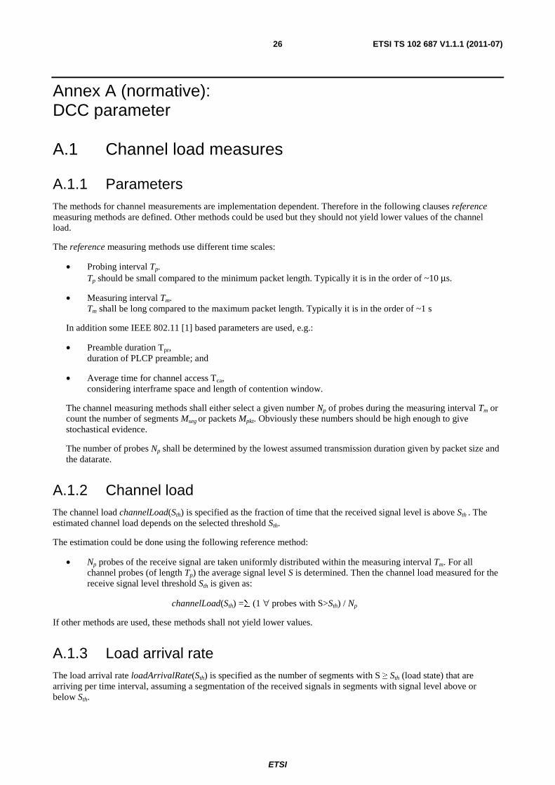
A.1.1 Parameters The methods for channel measurements are implementation dependent. Therefore in the following clauses reference measuring methods are defined. Other methods could be used but they should not yield lower values of the channel load.
The reference measuring methods use different time scales:
• Probing interval Tp. Tp should be small compared to the minimum packet length. Typically it is in the order of ~10 μs.
• Measuring interval Tm. Tm shall be long compared to the maximum packet length. Typically it is in the order of ~1 s
In addition some IEEE 802.11 [1] based parameters are used, e.g.:
• Preamble duration Tpr, duration of PLCP preamble; and
• Average time for channel access Tca, considering interframe space and length of contention window.
The channel measuring methods shall either select a given number Np of probes during the measuring interval Tm or count the number of segments Mseg or packets Mpkt. Obviously these numbers should be high enough to give stochastical evidence.
The number of probes Np shall be determined by the lowest assumed transmission duration given by packet size and the datarate.
A.1.2 Channel load The channel load channelLoad(Sth) is specified as the fraction of time that the received signal level is above Sth . The estimated channel load depends on the selected threshold Sth.
The estimation could be done using the following reference method:
• Np probes of the receive signal are taken uniformly distributed within the measuring interval Tm. For all channel probes (of length Tp) the average signal level S is determined. Then the channel load measured for the receive signal level threshold Sth is given as:
channelLoad(Sth) =∑ (1 ∀ probes with S>Sth) / Np
If other methods are used, these methods shall not yield lower values.
A.1.3 Load arrival rate The load arrival rate loadArrivalRate(Sth) is specified as the number of segments with S ≥ Sth (load state) that are arriving per time interval, assuming a segmentation of the received signals in segments with signal level above or below Sth.
ETSI
ETSI TS 102 687 V1.1.1 (2011-07)27
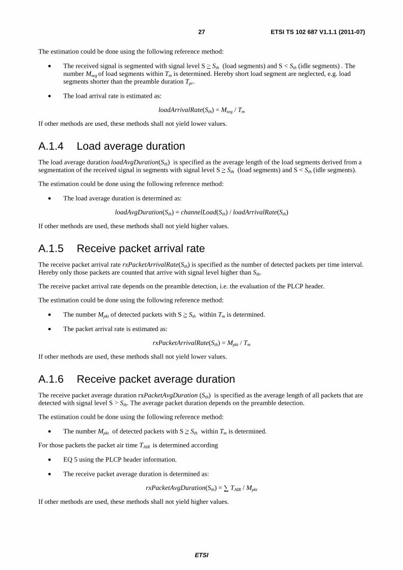
The estimation could be done using the following reference method:
• The received signal is segmented with signal level S ≥ Sth (load segments) and S < Sth (idle segments) . The number Mseg of load segments within Tm is determined. Hereby short load segment are neglected, e.g. load segments shorter than the preamble duration Tpr.
• The load arrival rate is estimated as:
loadArrivalRate(Sth) = Mseg / Tm
If other methods are used, these methods shall not yield lower values.
A.1.4 Load average duration The load average duration loadAvgDuration(Sth) is specified as the average length of the load segments derived from a segmentation of the received signal in segments with signal level S ≥ Sth (load segments) and S < Sth (idle segments).
The estimation could be done using the following reference method:
• The load average duration is determined as:
loadAvgDuration(Sth) = channelLoad(Sth) / loadArrivalRate(Sth)
If other methods are used, these methods shall not yield higher values.
A.1.5 Receive packet arrival rate The receive packet arrival rate rxPacketArrivalRate(Sth) is specified as the number of detected packets per time interval. Hereby only those packets are counted that arrive with signal level higher than Sth.
The receive packet arrival rate depends on the preamble detection, i.e. the evaluation of the PLCP header.
The estimation could be done using the following reference method:
• The number Mpkt of detected packets with S ≥ Sth within Tm is determined.
• The packet arrival rate is estimated as:
rxPacketArrivalRate(Sth) = Mpkt / Tm
If other methods are used, these methods shall not yield lower values.
A.1.6 Receive packet average duration The receive packet average duration rxPacketAvgDuration (Sth) is specified as the average length of all packets that are detected with signal level S ≥ Sth. The average packet duration depends on the preamble detection.
The estimation could be done using the following reference method:
• The number Mpkt of detected packets with S ≥ Sth within Tm is determined.
For those packets the packet air time TAIR is determined according
• EQ 5 using the PLCP header information.
• The receive packet average duration is determined as:
rxPacketAvgDuration(Sth) = ∑ TAIR / Mpkt
If other methods are used, these methods shall not yield higher values.
ETSI
ETSI TS 102 687 V1.1.1 (2011-07)28
A.1.7 Packet Occupancy The packet occupancy packetOccupancy(Sth) is specified as the fraction of time that the channel is occupied by packets detected with receive signal level above Sth including the waiting times between subsequent packets due to channel access.
Therefore a packetOccupancy(Sth) = 100 % occurs if the detected packets with S ≥ Sth are ideally lined up.
The packetOccupancy can be estimated by the following reference method:
• The packet occupancy is determined as:
packetOccupancy(Sth) = rxPacketArrivalRate(Sth) * (rxPacketAvgDuration(Sth) + TCA)
If other methods are used, these methods shall not yield lower values.
A.1.8 Channel busy time The channel busy time channelBusyTime is specified as the fraction of time the channel is regarded as busy, i.e. when one of the following conditions are met:
• A detected packet has a higher signal level than NDL_defDccSensitivity.
• The received signal level is higher than NDL_defCarrierSense.
The estimation could be done using the following reference method:
• The received signal is segmented in busy and idle channel states: The channel is sensed busy for the duration of detected packets with S ≥ NDL_defDccSensitivity. Furthermore the channel is sensed busy if the received signal level is higher than NDL_defCarrierSense. This defines the channel busy signal.
• Np probes of the channel busy signal are taken uniformly distributed within the measuring interval Tm. An estimation of the channel busy time is given by:
channelBusyTime = ∑ (1 ∀ probes with channel busy) / Np
If other methods are used, these methods shall not yield lower values.
NOTE: The reference method uses an ensemble average that is equivalent to time averaging (OFDM regarded as ergodic process).
A.2 Transmit packet statistics
A.2.1 Transmit packet rate The transmit packet rate txPacketRate(acPrio) is specified as the number of packets with priority equal to acPrio that are locally transmitted per unit of time.
The estimation could be done using the following reference method:
• Count Mpkt (acPrio), i.e. the number of transmitted packets with priority equal to acPrio during a measuring period of Tm.
• The transmit packet rate is determined as:
txPacketRate(acPrio) = Mpkt (acPrio) / Tm
NOTE 1: The measuring period Tm should be high enough to give stochastical evidence. Typically Tm is in the order of ~10 s.
NOTE 2: The measuring parameters Mpkt and Tm are defined in Clause A.1.1.
ETSI
ETSI TS 102 687 V1.1.1 (2011-07)29
If other methods are used, these methods shall not yield lower values.
A.2.2 Transmit packet average duration The transmit packet average duration txPacketAvgDuration(acPrio) is specified as the average duration of packets with priority equal to acPrio that are transmitted per time unit.
The estimation could be done using the following reference method:
• Count Mpkt (acPrio), i.e. the number of transmitted packets with priority equal to acPrio during a measuring period of Tm.
For those packets the packet air time TAIR is determined according
• EQ 5 using the PLCP header information.
• The transmit packet average duration is determined as:
txPacketAvgDuration(acPrio) = ∑TAIR (∀ packets with priority = acPrio) / Tm
If other methods are used, these methods shall not yield lower values.
A.2.3 Average transmit signal power The transmit signal average power txSignalAvgPower(acPrio) is specified as the average signal power of packets with priority equal to acPrio.
The estimation could be done using the following reference method:
• Count Mpkt (acPrio), i.e. the number of transmitted packets with priority equal to acPrio during a measuring period of Tm.
For those packets the air time TAIR is determined according
• EQ 5 using the PLCP header information.
• For those packets the signal power SP is determined (in decibel).
• The average transmit signal power is determined as:
txSignalAvgPower(acPrio) = dB((∑ (TAIR * dBinv(SP)))/ ∑ TAIR)
If other methods are used, these methods shall not yield lower values.
A.2.4 Transmit channel use The cumulative transmit channel use txChannelUse(acPrio) is specified as the fraction of time that the ITS station transmit packets with an priority less or equal to acPrio.
The estimation could be done using the following reference method:
txChannelUse(acPrio) = ∑n=0…acPrio txArrivalRate(n) * txPacketAvgDuration(n).

ETSI
ETSI TS 102 687 V1.1.1 (2011-07)30
A.3 Communication Ranges
A.3.1 Carrier Sense Range DCC_access shall provide the estimated detection range carrierSenseRange(txPower). The detection range is specified as a distance between transmitter and receiver within which the detection of that packet is very likely assuming a free channel and the pathloss channel model.
The definition of the pathloss channel model is based on NDL_maxCsRange with:
carrierSenseRange(NDL_maxTxPower) = NDL_maxCsRange
Using less transmit power txPower the detection range shrinks according to the signal power backoff:
txPowerBackoff = NDL_maxTxPower − txPower
Using the pathloss channel model the receive signal power is calculated:
rxPower(txPower, distance) = NDL_defDccSensitivity − txPowerBackoff − NDL_refPathLoss * dB(distance / NDL_maxCsRange)
with the decibel function y=dB(x)=10*log10(x) and the inverse decibel function x=dBinv(y)=10y/10.
Solving rxPower(txPower, carrierSenseRange(txPower)) = NDL_defDccSensitivity yields
EQ 26: carrierSenseRange(txPower) = maxCarrierSenseRange * dBinv(−txPowerBackoff / NDL_refPathloss)
EXAMPLE: NDL_maxTxPower=33 dBm, NDL_refPathloss=2,5 and NDL_maxCsRange=1 000 m, ⇒ carrierSenseRange(23 dBm) = 398 m ⇒ carrierSenseRange(13 dBm) = 158 m
A.3.2 Estimated communication range DCC_access shall provide the estimated communication range estCommRange(txPower, datarate) dependent on the transmit signal power txPower and the datarate assuming the SNR demodulation model.
EQ 27: estCommRange(txPower, datarate) = carrierSenseRange(txPower) * dBinv(−ΔSNR(datarate) / NDL_refPathloss)
The SNR backoff ΔSNR(datarate) is taken from Table 8.
EXAMPLE NDL_maxTxPower=33 dBm, NDL_refPathloss=2,5 and NDL_maxCsRange=1 000 m, ⇒ estCommRange(13 dBm, 12 Mbit/s) = 76 m
A.3.3 Estimated communication range under interference DCC_access shall provide the estimated reliable communication range under interference that is specified as that range where hidden stations do not have a significant impact, according to the receive model.
EQ 28: estCommRangeIntf (txPower, datarate) = refCarrierSenseRange / (1+dBinv(gamma(txPower, datarate) / NDL_refPathloss))
Hereby all stations are assumed to transmit with refTxPower. This leads to the reference detection range:
EQ 29: refCarrierSenseRange = carrierSenseRange(NDL_refTxPower)
with
EQ 30: gamma(txPower, datarate) = requiredSnr(datarate) + (NDL_refTxPower - txPower)

ETSI
ETSI TS 102 687 V1.1.1 (2011-07)31
A.4 Network Design Limits
A.4.1 NDL types and formats In table A.1 the NDL types and formats are given. All parameters are encoded as INTEGER number with a given range. A reference value and a step size are given, such that the corresponding physical value is given by:
physicalValue = referenceValue + number * stepSize
The NDL types and formats can be accessed directly or via the table index.
Table A.1: NDL types and formats
Type Format stepSize referenceValue ndlType_acPrio INTEGER (0...7) 1 number ndlType_controlLoop INTEGER (0...7) 1 0 ndlType_arrivalRate INTEGER (0..8191) 0,01 /s 0 ndlType_channelLoad INTEGER (0..1000) 0,1 % 0 % ndlType_channelUse INTEGER (0..8000) 0,0125 % 0 % ndlType_datarate INTEGER (0..7) Table 8 ndlType_distance INTEGER (0..4095) 1 m 0 ndlType_numberElements INTEGER (0..63) number ndlType_packetDuration INTEGER (0..2047) TSYM 0 ndlType_packetInterval INTEGER (0..1023) 10 ms 0 ndlType_pathloss INTEGER (0..31) 0,1 1,0 ndlType_rxPower INTEGER (0..127) -0,5 dB -40 dBm ndlType_snr INTEGER (0..127) 0,5 dB -10 dB ndlType_timing INTEGER (0..4095) 10 ms 0 ndlType_txPower INTEGER (0..127) 0,5 dB -20 dBm ndlType_ratio INTEGER (0..100) 1 % 0 % ndlType_exponent INTEGER (0..100) 0,1 0 ndlType_queueStatus Enumeration Table A.2 ndlType_dccMechanism Bitset Table A.2
A.4.2 NDL Input parameter and constants
Table A.2: Enumeration, Bitset, Indices and Constants
Bitset and Enumeration Variable Type Reference ndlType_dccMechanism asDcc 1= TPC; 2= TRC; 4=TDC;
8= DSC; 16=TAC;32=reserved; remark: 0=NONE; 63= ALL
Clause 6.4.2
ndlType_queueStatus 0=CLOSED, 1=OPEN Indices Type Reference
ndlType_acPrio acPrio ndlType_acPrio Clause 6.1 ndlType_datarate datarate ndlType_datarate Table 8

ETSI
ETSI TS 102 687 V1.1.1 (2011-07)32
A.4.3 NDL database
Table A.3: NDL database
Transmit power threshold ACR Type Default Ref. NDL_minTxPower RR
ndlType_txPower Table A.5 Table 1 NDL_maxTxPower RR NDL_defTxPower(acPrio) RR NDL_refTxPower(acPrio) WW
Packet timing thresholds NDL_maxPacketDuration(acPrio) RW ndlType_packetDuration
Table A.6 Table 2 NDL_minPacketInterval RW
ndlType_packetInterval NDL_maxPacketInterval RW NDL_defPacketInterval(acPrio) RW NDL_refPacketInterval(acPrio) WW
Packet datarate thresholds NDL_minDatarate RR
ndlType_datarate Table A.7 Table 3 NDL_maxDatarate RR NDL_defDatarate(acPrio) RW NDL_refDatarate(acPrio) WW
Receive signal thresholds NDL_minCarrierSense RR
ndlType_rxPower
-95 dBm
Table 4 NDL_maxCarrierSense RR -65 dBm NDL_defCarrierSense RR -85 dBm NDL_refCarrierSense WW -85 dBm
Receive model parameter NDL_defDccSensitivity RC ndlType_rxPower -85 dBm
Table 7 NDL_maxCsRange RC ndlType_distance 1 000 m NDL_refPathloss RC ndlType_pathloss 2,0 NDL_minSNR RC ndlType_snr 10 dB
Demodulation model parameter NDL_snrBackoff(datarate) RC ndlType_snr Table 8
Transmit model parameter NDL_tmPacketArrivalRate(acPrio) WR ndlType_arrivalRate
n.a. NDL_tmPacketAvgDuration(acPrio) WR ndlType_packetDuration NDL_tmSignalAvgPower(acPrio) WR ndlType_txPower NDL_maxChannelUse WR
ndlType_channelUse See note 2 Table 6 NDL_tmChannelUse(acPrio) WR
Channel load thresholds NDL_minChannelLoad RC
ndlType_channelLoad Table A.8 Table 11 NDL_maxChannelLoad RC
Transmit queue parameter NDL_numQueue RR ndlType_acPrio 4 Table 5 NDL_refQueueStatus(acPrio) WW ndlType_queueStatus OPEN NDL_queueLen(acPrio) RC ndlType_numberElements Table A.9 Table 10 NOTE 1: The ACR column indicates the access rights for DCC_access (1st letter) and other DCC components
(2nd letter): X: no access, R: read-only access, W: read-write access everytime, C: read-write once access (before startup).
NOTE 2: NDL_maxChannelUse and NDL_tmChannelUse(acPrio) could be used by other DCC components, e.g. DCC_mgmt or DCC_net, to support various channel usage schemes.

ETSI
ETSI TS 102 687 V1.1.1 (2011-07)33
A.4.4 NDL output parameters
Table A.4: Output parameter
Demodulation model ACR NDL_requiredSnr(datarate) WR ndlType_snr Clause 5.7.3
Communication ranges NDL_carrierSenseRange (txPower) WR ndlType_distance
Table 9 NDL_estCommRange(txPower, datarate) WR ndlType_distance NDL_estCommRangeIntf(txPower, datarate) WR ndlType_distance
Channel load measures NDL_channelLoad (ds) WR ndlType_channelLoad
Table 11
NDL_loadArrivalRate(ds) WR ndlType_arrivalRate NDL_loadAvgDuration(ds) WR ndlType_packetDuration NDL_packetArrivalRate(ds) WR ndlType_arrivalRate NDL_packetAvgDuration(ds) WR ndlType_packetDuration NDL_channelBusyTime(ds, cs) WR ndlType_channelLoad
Transmit packet statistics NDL_txPacketArrivalRate(acPrio) WR ndlType_arrivalRate
Table 12 NDL_txPacketAvgDuration(acPrio) WR ndlType_packetDuration NDL_txChannelUse(acPrio) WR ndlType_channelUse NDL_txSignalAvgPower(acPrio) WR ndlType_txPower
A.4.5 Channel dependent parameter
Table A.5: Transmit power defaults
Transmit power defaults
ACR G5CC G5SC
NDL_maxTxPower RW 33 dBm 33 dBm NDL_minTxPower RW -10 dBm -10 dBm NDL_defTxPower RW 23 dBm 23 dBm
Table A.6: Packet timing defaults
Transmit power defaults ACR G5CC G5SC NDL_maxPacketDuration RC 0,6 ms 1,0 ms NDL_minPacketInterval RC 0,04 s 0,04 s NDL_maxPacketInterval RC 1 s 2 s NDL_defPacketInterval RC 0,5 s 0,5 s
Table A.7: Packet datarate defaults
Transmit power defaults ACR G5CC G5SC NDL_minDatarate RR 3 Mbit/s 6 Mbit/s NDL_maxDatarate RR 12 Mbit/s 18 Mbit/s NDL_defDatarate RR 6 Mbit/s 6 Mbit/s
Table A.8: Channel load defaults
Transmit power defaults ACR G5CC G5SC NDL_minChannelLoad RR 15 % 20 % NDL_maxChannelLoad RR 40 % 50 %

ETSI
ETSI TS 102 687 V1.1.1 (2011-07)34
A.4.6 Priority dependent parameters
Table A.9: DCC transmit queuing defaults
DCC Transmit queuing default
ACR Type G5CC G5SC
NDL_queueLen(AC_VI) RC ndlType_numberElements 2 8 NDL_queueLen(AC_VO) RC ndlType_numberElements 2 8 NDL_queueLen(AC_BE) RC ndlType_numberElements 2 8 NDL_queueLen(AC_BK) RC ndlType_numberElements 2 8
A.4.7 Basic control loop NDL database
Table A.10: Basic DCC configuration
Generel configuration ACR Type G5CC G5SC NDL_timeUp RW ndlType_timing 1 s 1 s NDL_timeDown RW ndlType_timing 5 s 5 s NDL_numActiveState RR ndlType_numberElements 1 4 NDL_curActiveState WR ndlType_numberElements 0 0
Active state configuration (Clause 6.4.3) NDL_asStateId RW ndlType_numberElements
Table A.11 Table A.12
NDL_asTimeDn RW ndlType_timing NDL_asChanLoad RW ndlType_channelLoad NDL_asDcc RW ndlType_dccMechanism NDL_asTxPower(acPrio) RW ndlType_txPower NDL_asPacketInterval(acPrio) RW ndlType_packetInterval NDL_asDatarate(acPrio) RW ndlType_dataRate NDL_asCarrierSense(acPrio) RW ndlType_rxPower
NOTE 1: Active state configuration is an array of NDL_numActiveState elements.
Table A.11: Default configuration G5CC
Value Active 1 AC_VI AC_VO AC_BE AC_BK asStateId 1 NDL_asChanLoad 20 % NDL_asDcc 0 TPC TPC TPC NDL_asTxPower [dBm] ref 25 20 15 NDL_asPacketInterval ref ref ref ref NDL_asDatarate ref ref ref ref NDL_asCarrierSense ref ref ref ref
NOTE 2: Value ref indicates that the parameter is unchanged and the previous value of the corresponding reference parameter is used, e.g. NDL_asTxPower = NDL_refTxPower.
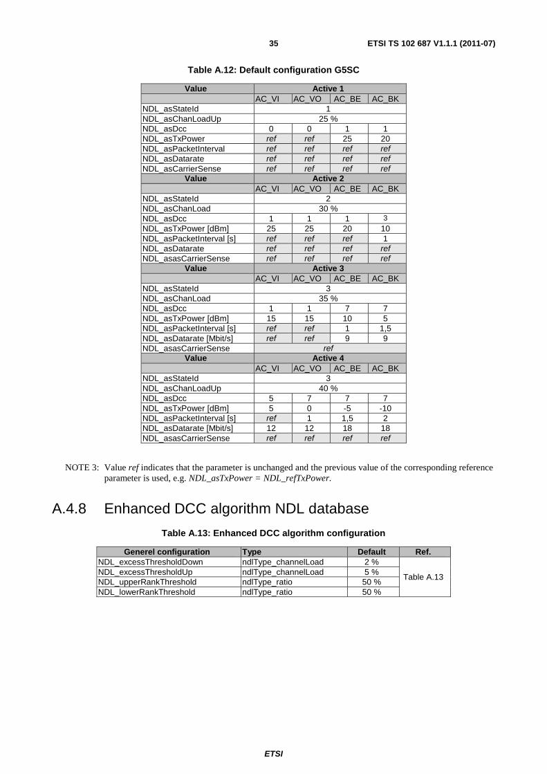
ETSI
ETSI TS 102 687 V1.1.1 (2011-07)35
Table A.12: Default configuration G5SC
Value Active 1 AC_VI AC_VO AC_BE AC_BK NDL_asStateId 1 NDL_asChanLoadUp 25 % NDL_asDcc 0 0 1 1 NDL_asTxPower ref ref 25 20 NDL_asPacketInterval ref ref ref ref NDL_asDatarate ref ref ref ref NDL_asCarrierSense ref ref ref ref
Value Active 2 AC_VI AC_VO AC_BE AC_BK NDL_asStateId 2 NDL_asChanLoad 30 % NDL_asDcc 1 1 1 3
NDL_asTxPower [dBm] 25 25 20 10 NDL_asPacketInterval [s] ref ref ref 1 NDL_asDatarate ref ref ref ref NDL_asasCarrierSense ref ref ref ref
Value Active 3 AC_VI AC_VO AC_BE AC_BK NDL_asStateId 3 NDL_asChanLoad 35 % NDL_asDcc 1 1 7 7 NDL_asTxPower [dBm] 15 15 10 5 NDL_asPacketInterval [s] ref ref 1 1,5 NDL_asDatarate [Mbit/s] ref ref 9 9 NDL_asasCarrierSense ref
Value Active 4 AC_VI AC_VO AC_BE AC_BK NDL_asStateId 3 NDL_asChanLoadUp 40 % NDL_asDcc 5 7 7 7 NDL_asTxPower [dBm] 5 0 -5 -10 NDL_asPacketInterval [s] ref 1 1,5 2 NDL_asDatarate [Mbit/s] 12 12 18 18 NDL_asasCarrierSense ref ref ref ref
NOTE 3: Value ref indicates that the parameter is unchanged and the previous value of the corresponding reference parameter is used, e.g. NDL_asTxPower = NDL_refTxPower.
A.4.8 Enhanced DCC algorithm NDL database
Table A.13: Enhanced DCC algorithm configuration
Generel configuration Type Default Ref. NDL_excessThresholdDown ndlType_channelLoad 2 %
Table A.13 NDL_excessThresholdUp ndlType_channelLoad 5 % NDL_upperRankThreshold ndlType_ratio 50 % NDL_lowerRankThreshold ndlType_ratio 50 %

ETSI
ETSI TS 102 687 V1.1.1 (2011-07)36
Annex B (informative): Transmit power calibration
B.1 Common principles of transmit power calibration To ensure fair use of the radio resources and a proper functioning of the DCC methods, the RF output power level of an ITS station should be calibrated.
Clauses B.2 and B.3 describe two calibration methods. that are sufficient to certify defined transmit power levels and transmit power steps of an ITS station. The calibration itself is out of scope of the present document. If other calibration methods are used the accuracy should not be less that the accuracy of the proposed methods. The appropriate method is chosen by the nature of the ITS station. If it is an inherent unchangeable part of another entity, like a vehicle, the method described in Clause B.2 is suited. If the ITS station consists of discrete parts that can be combined in different ways, like a transmitter, cabling, and antenna, the method described in Clause B.3 applies.
Clause B.4 lists the transmit power levels and their recommended accuracy to be use for the certification process.
B.2 Transmit power certification process for non modular ITS stations
B.2.1 Applicability and overview for non modular ITS stations The transmit power calibration procedure described in Clause B.2 applies to ITS stations that are an inherent unchangeable part of another entity, or to ITS stations where the RF transmitter and the antenna are connected in a way that prevents them from detachment. In the following this entity will be called DUT.
EXAMPLE: The ITS station is part of a vehicle. The RF transmitter and the antenna are in the same housing.
The calibration is performed in two steps. First the antenna pattern of the UUT is determined according to Clause B.2.2, than the maximum e.i.r.p. is measured according to Clause B.2.3.
B.2.2 Determination of antenna pattern for non modular ITS stations
The determination of the antenna pattern is needed to find the direction of maximum e.i.r.p. (boresight).
If the manufacturer declares borsight for a directional antenna with a gain of more than 6 dBi, no antenna pattern measurement is necessary. Otherwise the antenna pattern should be measured according to following procedure.
For correct placement of the UUT during measurement, the manufacturer should declare how the UUT is placed or mounted during normal operation.
EXAMPLE: A vehicle is placed on a horizontal street. A fixed ITS station uses an antenna with defined mounting requirements.
The antenna pattern of the UUT should be measured in free space. The antenna patter of the UUT should be measured with 5° steps in azimuth and elevation angle.
The direction of the e.i.r.p. measurement is given by the direction of the maximum measured antenna gain. To determine this maximum, the absolute antenna gain is irrelevant, only the relative accuracy should be below ±1 dB.
The detailed description of the test procedure and setup is, though necessary, out of scope of the present document.
ETSI
ETSI TS 102 687 V1.1.1 (2011-07)37
B.2.3 Measurement of e.i.r.p. for non modular ITS stations If the antenna of the UUT is intended to be directional with a gain of more than 6 dBi than the e.i.r.p. should be measured in boresight as declared by the manufacturer.
If the antenna gain does not exceed 6 dBi in any direction, the e.i.r.p. is measured in the direction that was determined in the measurement as described in Clause B.2.2.
The measurement uncertainty of the e.i.r.p. test equipment should be less than ±1 dB. With this test equipment the measured e.i.r.p. should be the nominal value from Clause B.4 ±3 dB.
B.3 Transmit power certification process for modular ITS stations
B.3.1 Applicability and overview for modular ITS stations This transmit power calibration procedure applies to ITS stations that consist of discrete parts that can be combined in different ways.
EXAMPLE: The ITS transmitter and the antenna are connected by an interchangeable cable. An ITS transmitter can be equipped with different antennas.
The calibration is done in three steps:
• The maximum antenna gain of all antennas to be certified is measured (see Clause B.3.2).
• The cable loss of all cables to be certified is measured (see Clause B.3.3).
• The transmit output power level is measured for all configurations to be certified (see Clause B.3.4).
B.3.2 Determination of antenna pattern for modular ITS stations The same procedure that was described for the whole UUT in Clause B.2.2 applies to the determination of the antenna pattern for a modular ITS station. But in case of a modular ITS station the antenna gain should be measured with an absolute accuracy of ±1 dB.
B.3.3 Determination of cable loss for modular ITS stations If the antenna is connected by a cable to the transmitter, the loss of this cable should be measured with an accuracy of ±1 dB.
B.3.4 Determination of output power level for modular ITS stations
If more than one combination of transmitter, cable, and antenna are certified, than a tool should exist that allows configuring of the transmitter to compensate for the appropriate cable loss and antenna gain.
The nominal compensated output power level PTX of the transmitter can be calculated from the in Clause B.4 specified e.i.r.p. level, the maximum measured antenna gain gA, and the cable loss ac:
PTXnom = e.i.r.p. - gA + ac
NOTE: If the antenna is directly plugged to the transmitter connector ac is zero.
The output power level of the transmitter should be measured with an accuracy of ±1 dB. With this test equipment the measured output power level of the transmitter should be in the range of PTXnom ±2 dB.

ETSI
ETSI TS 102 687 V1.1.1 (2011-07)38
B.4 Specified e.i.r.p. levels and step requirements to be calibrated
Each of following e.i.r.p. levels at which an ITS station is capable to transmit, should be calibrated according to the procedure described in Clauses B.2 or B.3.
Table B.1: Calibration levels
e.i.r.p. -10 dBm 0 dBm 10 dBm 20 dBm 26 dBm 33 dBm
In between the calibrated values, the output power level should be adjustable in steps with a maximum step size of 3 dB. The step size must not be calibrated, but the steps should be monotonic.
NOTE: It is recommended to use a small but monotonic step size of approximately 1 dB or even less.

ETSI
ETSI TS 102 687 V1.1.1 (2011-07)39
Annex C (informative): Example of a DCC_Net algorithm
C.1 Enhanced DCC algorithm The enhanced DCC algorithm is an alternative to the ACTIVE state control loop described in Clause 6.4 in order to improve the performance and the stability of the overall basic DCC algorithm. As such, the enhanced DCC algorithm is only applied during the ACTIVE state of the basic DCC algorithm. The enhanced DCC algorithm is a DCC_Net algorithm because it is based on remote information (Clause C.2) transmitted in the LLC header.
The enhanced DCC control loop implementation uses additional DCC information from neighboring stations, e.g. the measured channel load, the currently used transmit power value and packet generation rates as provided by the DCC header defined in Clause C.2, to decide whether to increase or decrease the own transmission parameters.
The used transmission parameter values and channel load observations sent by neighbors should be collected by the DCC_access layer upon reception of a packet and should be stored in separate data structures to maintain the currently used transmit power, the currently used transmit packet rate and the observed channel load of the neighbors. In particular, the DCC_access should maintain the following data structures:
1) Data structure N as the set of all neighbors from which a DCC header has been received during the past second.
2) Data structure T:= {tn : n ∈ N} as the set of transmit powers currently used by the neighbors listed in N including the own power value stored in NDL_refTxPower.
3) Data structure R:= {rn : n ∈ N} as the set of transmit packet rates currently used by the neighbors listed in N including the own rate value indicated by NDL_refPacketInterval.
4) Data structure CL:= {cn : n ∈ N} as the set of channel load values currently observed by the neighbors listed in N, excluding the own observation.
Based on the information received by neighbors, the enhanced DCC algorithm should work as follows:
1) Compute the average amount of channel load excess Eabove and lower deviation Ebelow over all neighbors in N:
Eabove := (1 / |N|) ∑ max (0, cn - NDL_maxChannelUse)
Ebelow := (1 / |N|) ∑ max (0, NDL_maxChannelUse - cn)
2) Compute the values pT and pR, such that they reflect the own position inside the (ranked) lists T and R (at increasing order).
3) Compare Eabove and Ebelow with maximum excess threshold NDL_excessThresholdUp and lower deviation threshold NDL_excessThresholdDown:
a) If (Eabove > NDL_excessThresholdUp) check the following conditions:
i) If ((pT / |N|) > NDL_upperRankThreshold) → decrease NDL_refTxPower
ii) If ((pR / |N|) > NDL_upperRankThreshold) → increase NDL_refPacketInterval
b) If (Ebelow > NDL_excessThresholdDown) check the following conditions:
i) If ((pT / |N|) < NDL_lowerRankThreshold) → increase NDL_refTxPower
ii) If ((pR / |N|) < NDL_lowerRankThreshold) → decrease NDL_refPacketInterval

ETSI
ETSI TS 102 687 V1.1.1 (2011-07)40
The above algorithm is illustrated in Figure C.1 and ensures that every node obtains a network view on the currently observed channel load and the currently used transmit parameters. Based on this view, it is determined whether any action has to be taken by the network as a whole in order to reduce the channel load (step 1) and finally whether the node itself participates in the distributed action. The latter decision is based on a comparison of the own transmit power/packet rate and the settings currently used by the neighbors, i.e. it is checked whether the node belongs to the relative subset of nodes that is using the highest/lowest transmission parameter configuration. Table 17 lists the default values for the thresholds NDL_excessThresholdUp, NDL_excessThresholdDown, NDL_upperRankThreshold and NDL_lowerRankThreshold.
Table C.1: Enhanced DCC algorithm configuration
DCC parameters Value Definition NDL_excessThresholdUp 2 % Excess threshold required to reduce TX parameters NDL_excessThresholdDown 5 % Lower deviation threshold required to increase TX parameters NDL_upperRankThreshold 50 % Threshold for classification of nodes with highest TX parameters NDL_lowerRankThreshold 50 % Threshold for classification of nodes with lowest TX parameters
Figure C.1: Enhanced DCC algorithm
NOTE: The thresholds NDL_excessThresholdDown, NDL_excessThresholdUp, NDL_upperRankThreshold and NDL_lowerRankThreshold are used to tune the sensitivity of the protocol, and to address the convergence time versus oscillation tradeoff.
C.2 Remote information For defining an enhanced control algorithm (Clause C.1) the following information of surrounding ITS stations is needed: the average transmit power level currently used, the observed channel load, the average transmit interval timing and the applied CCA sensitivity threshold. For this a DCC header is introduced, immediately follows the SNAP header. Another option would be to exchange this information on DCC network layer.

ETSI
ETSI TS 102 687 V1.1.1 (2011-07)41
Currently all 802.11 frames are sent as Type1, UI command frames defined by LLC Control field values 0x03 (see IEEE 802.2 [6], Figure 10). To define the Frames as Type 1, UI command frames + DCC header the value 0x07 is used in the LLC Control field. This value does not conflict with any defined values (see IEEE 802.2 [6], Figures 10 and 16).
LLC
Control
Opt. DCC
header
SSAP
=0xAA
DSAP
=0xAANPDUSNAP OUI SNAP Pid
Figure C.2: DCC LLC structure
The DCC header itself contains the values needed for running the enhanced DCC algorithm.
Figure C.3: DCC header structure
Header length
1 octet in length. Length of DCC header including this length field.
Header version
1 octet in length. Version for the DCC header.
DCC Header Data
4 octets in length. Contains:
• the observed channel load value (during the last second) as of type ndlType_channelLoad;
• the used transmit power of type ndlType_txPower;
• the used transmission interval of type ndlType_timing;
• the applied CCA sensitivity value with a step size of 1dB ranging between NDL_minCarrierSense and NDL_maxCarrierSense.

ETSI
ETSI TS 102 687 V1.1.1 (2011-07)42
Annex D (informative): Validation
D.1 Validation scenarios Systematic validation scenarios are used to verify algorithm behaviour. Since it is possible to overwrite some components of DCC_access by corresponding methods of other DCC components (e.g. DCC_net) these other methods should be verified using the validation scenarios and performance criteria as described in this annex.
Validation scenarios are classified based on two factors:
a) Extent of dynamic environment - Quantified as the number of new observed vehicles and vehicles no longer observed during a time unit. The main tool to emulate changing environment is adding mobility to the validation, manifested by different speed per vehicles and non-uniform space distribution. A dynamic environment challenges the algorithm by having to adapt to a changing situation.
b) Ratio of hidden stations - Quantified as ratio between neighbours within carrier sense range that potentially may receive hidden station transmissions and total number of neighbours within carrier sense range. The simplest increasing hidden station ratio is testing around urban intersections. High ratio of hidden stations will increase the difficulty of an algorithm to predict the current congestion in surrounding area.
These 2 factors are creating 4 scenarios: "Parking lot", "Clogged city", "Highway" and "Urban mobility".
1) "Parking lot" - static environment at low ratio of hidden stations
Figure D.1: "Parking lot" test scenario
Goal is basic sanity check.
2) "Clogged city" - static environment at high ratio of hidden stations. Buildings block direct transmission between close vehicles.
Figure D.2: "Clogged city" test scenario
3) "Highway" - dynamic environment with bidirectional multiple lanes road at low ratio of hidden stations.

ETSI
ETSI TS 102 687 V1.1.1 (2011-07)43
Figure D.3: "Highway" test scenario
Goal is testing ability to adjust to a varying environment
4) "Urban movement" - dynamic environment at high ratio of hidden stations.
Figure D.4: "Urban movement" test scenario
Goal is testing ability to adjust to a varying environment while maintaining fairness.
Additional parameters are configured for each of the combinations:
1) Vehicles' density - number of vehicles in a certain area.
2) Vehicles' speed.
D.2 Validation performance criteria The following criteria could be used to validate the algorithms.
Table D.1: Performance criteria
Criterion name Function Indication type Note Aggregated number of received packets
Incremented by any vehicle after any packet is received successfully
Network capacity Transmitted packet may be counted multiple times
Aggregated number of packet collisions
Incremented by any vehicle after any packet is badly received due to collision
Responsiveness and reach
Weak indication since two contradicting indications are mixed
Transmit power deviation over area
Standard deviation of transmission power of vehicles inside an area (e.g. 1 000 sqm segment) in a given time unit (e.g. 1 second), averaged over time and over area.
Fairness and convergences
Vehicles in close proximity should use similar transmission power
Transmit power variation
Average over time of vehicles' transmission power variation during a time unit (e.g. 1 second)
Stability Detecting oscillations
Average distance Average of distance between source and receiver for all valid packets
Reachability Most important parameter from safety application perspective

ETSI
ETSI TS 102 687 V1.1.1 (2011-07)44
Annex E (informative): Bibliography
• Joining Forces for VANETs: A Combined Transmit Power and Rate Control Algorithm Roberto Baldessari, Damiano Scanferla, Long Le, Wenhui Zhang, Andreas Festag NEC Europe Ltd., Network Laboratories, Universit`a degli Studi di Padova Proceedings of WIT2010, Hamburg, Germany.
• Evaluation of Time-Space Efficiency in CSMA/CA and Slotted Vanets Riccardo Scopigno, Hector Agustin Cozzetti Istituto Superiore Mario Boella, Turin, Italia Proceedings of VTC2010-4, Ottawa, Canada.
• Architecture for Decentralized Mitigation of Local Congestion in VANETs. Robert K. Schmidt, Tim Leinmüller, Bert Böddeker, DENSO AUTOMOTIVE Deutschland GmbH, Germany; Achim Brakemeier, Daimler AG, Research and Technology, Ulm Germany; Günter Schäfer: Telematics/Computer Networks Research Group, Technische Universität Ilmenau, Germany. 2010 International Conference on ITS Telecommunications (ITST 2010, Nov 9-11, 2010), Kyoto, Japan.
• C2C-CC White Paper on Network Design Limits and VANET performance Achim Brakemeier, Daimler AG, v0.6(2009-01).
NOTE: Available at www.car-2-car.org.
• Path Loss Modeling for Vehicle-to-Vehicle Communications Karedal, J.; Czink, N.; Paier, A.; Tufvesson, F.; Molisch, A.F.; Vehicular Technology, IEEE Transactions on, Volume: 60, Issue: 1 Publication Year: 2011 , Page(s): 323 - 328
NOTE: Available at: Path Loss Modeling for Vehicle-to-Vehicle Communications, Vehicular Technology, IEEE Transactions
• ECC/DEC/(08)01: "ECC Decision of 14 March 2008 on the harmonised use of the 5875-5925 MHz frequency band for Intelligent Transport Systems (ITS)".
• ECC/REC/(08)01: "ECC Recommendation (08)01 on the use of band 5855-5875 MHz for intelligent transport systems (ITS)".
• ECC Report 101: "Compatibility Studies in the Band 5855- 5925 MHz between Intelligent Transport Systems (ITS) and other Systems, Bern, February 2007".
• ETSI TS 102 636-3: "Intelligent Transport Systems (ITS); Vehicular Communications; GeoNetworking; Part 3: Network architecture".

ETSI
ETSI TS 102 687 V1.1.1 (2011-07)45
History
Document history
V1.1.1 July 2011 Publication