ts 102 744-3-8 - v1.1.1 - satellite earth stations and ... · etsi 5 etsi ts 102 744-3-8 v1.1.1...
TRANSCRIPT
ETSI TS 102 744-3-8 V1.1.1 (2015-10)
Satellite Earth Stations and Systems (SES); Family SL Satellite Radio Interface (Release 1);
Part 3: Control Plane and User Plane Specifications; Sub-part 8: NAS Layer and User Plane Operation
for MBMS Services
TECHNICAL SPECIFICATION
ETSI
ETSI TS 102 744-3-8 V1.1.1 (2015-10) 2
Reference DTS/SES-00299-3-8
Keywords 3GPP, GPRS, GSM, GSO, interface, MSS, radio,
satellite, TDM, TDMA, UMTS
ETSI
650 Route des Lucioles F-06921 Sophia Antipolis Cedex - FRANCE
Tel.: +33 4 92 94 42 00 Fax: +33 4 93 65 47 16
Siret N° 348 623 562 00017 - NAF 742 C
Association à but non lucratif enregistrée à la Sous-Préfecture de Grasse (06) N° 7803/88
Important notice
The present document can be downloaded from: http://www.etsi.org/standards-search
The present document may be made available in electronic versions and/or in print. The content of any electronic and/or print versions of the present document shall not be modified without the prior written authorization of ETSI. In case of any
existing or perceived difference in contents between such versions and/or in print, the only prevailing document is the print of the Portable Document Format (PDF) version kept on a specific network drive within ETSI Secretariat.
Users of the present document should be aware that the document may be subject to revision or change of status. Information on the current status of this and other ETSI documents is available at
http://portal.etsi.org/tb/status/status.asp
If you find errors in the present document, please send your comment to one of the following services: https://portal.etsi.org/People/CommiteeSupportStaff.aspx
Copyright Notification
No part may be reproduced or utilized in any form or by any means, electronic or mechanical, including photocopying and microfilm except as authorized by written permission of ETSI.
The content of the PDF version shall not be modified without the written authorization of ETSI. The copyright and the foregoing restriction extend to reproduction in all media.
© European Telecommunications Standards Institute 2015.
All rights reserved.
DECTTM, PLUGTESTSTM, UMTSTM and the ETSI logo are Trade Marks of ETSI registered for the benefit of its Members. 3GPPTM and LTE™ are Trade Marks of ETSI registered for the benefit of its Members and
of the 3GPP Organizational Partners. GSM® and the GSM logo are Trade Marks registered and owned by the GSM Association.
ETSI
ETSI TS 102 744-3-8 V1.1.1 (2015-10) 3
Contents Intellectual Property Rights ................................................................................................................................ 5
Foreword ............................................................................................................................................................. 5
Modal verbs terminology .................................................................................................................................... 5
Introduction ........................................................................................................................................................ 5
1 Scope ........................................................................................................................................................ 6
2 References ................................................................................................................................................ 6
2.1 Normative references ......................................................................................................................................... 6
2.2 Informative references ........................................................................................................................................ 7
3 Abbreviations ........................................................................................................................................... 7
4 Introduction .............................................................................................................................................. 7
4.1 Network Architecture ......................................................................................................................................... 7
4.2 Protocol Architecture ......................................................................................................................................... 8
5 MBMS NAS Layer Operations ................................................................................................................ 9
5.1 MBMS Mobility Management procedures ......................................................................................................... 9
5.1.1 GPRS Attach to BM Domain ........................................................................................................................ 9
5.1.1.1 Successful GPRS Attach Procedure ........................................................................................................ 9
5.1.1.2 Unsuccessful GPRS Attach Procedure .................................................................................................. 10
5.1.2 GPRS Detach .............................................................................................................................................. 10
5.1.2.0 General .................................................................................................................................................. 10
5.1.2.1 CN-initiated GPRS Detach Request ...................................................................................................... 10
5.1.2.2 UE-initiated GPRS Detach Request ...................................................................................................... 11
5.2 MBMS Service Management Procedures ......................................................................................................... 12
5.2.1 MBMS Service Activation .......................................................................................................................... 12
5.2.1.0 General .................................................................................................................................................. 12
5.2.1.1 MBMS Context Activation ................................................................................................................... 12
5.2.1.2 CN-initiated MBMS Context Activation .............................................................................................. 13
5.2.1.3 Unsuccessful MBMS Context Activation (Service not authorized) ...................................................... 14
5.2.1.4 Unsuccessful MBMS Context activation (Critical failure or Layer 2 establishment rejection) ............ 14
5.2.2 MBMS Context Deactivation ..................................................................................................................... 15
5.2.2.0 General .................................................................................................................................................. 15
5.2.2.1 UE Initiated MBMS Context Deactivation ........................................................................................... 15
5.2.2.2 Core Network Initiated MBMS Context Deactivation .......................................................................... 16
5.3 MBMS Bearer Management procedures .......................................................................................................... 16
5.3.1 Radio Access Bearer Release...................................................................................................................... 16
5.3.2 MBMS Radio Access Bearer Release ......................................................................................................... 17
5.3.3 MBMS Radio Access Bearer Modify ......................................................................................................... 17
5.3.4 MBMS Radio Access Bearer Modification Request .................................................................................. 17
5.3.5 MBMS Service modification ...................................................................................................................... 18
5.3.6 MBMS Service Removal ............................................................................................................................ 19
6 Mobility Management Behaviour .......................................................................................................... 20
6.1 Spot Beam Handover........................................................................................................................................ 20
6.2 Inter-RNC operation (via different satellites) ................................................................................................... 21
6.3 Inter-system mobility ....................................................................................................................................... 21
7 Exception handling ................................................................................................................................. 21
7.1 Forced Detach (CN Initiated) ........................................................................................................................... 21
7.2 Primary PDP Context deactivation (while MBMS Contexts present) .............................................................. 21
8 IP User Plane Handler for MBMS Services ........................................................................................... 22
8.0 General ............................................................................................................................................................. 22
8.1 UE-TE Controller triggered MBMS Services via R-interface .......................................................................... 22
8.1.1 Activation of MBMS Services .................................................................................................................... 22
8.1.2 Deactivation of MBMS Services ................................................................................................................ 22
8.2 Directly Connected TEs - use of IGMP as a trigger ......................................................................................... 22
ETSI
ETSI TS 102 744-3-8 V1.1.1 (2015-10) 4
8.2.0 General ........................................................................................................................................................ 22
8.2.1 Joining and leaving multicast services ........................................................................................................ 22
8.2.2 Maintenance of multicast services - IGMP query mechanism .................................................................... 23
8.3 Routers in the mobile domain - PIM-SM triggered MBMS Services .............................................................. 23
8.3.1 Joining and leaving multicast services ........................................................................................................ 23
8.3.2 Source Specific Multicast (SSM) and Any Source Multicast (ASM) with Rendezvous point in the terrestrial domain ........................................................................................................................................ 23
8.3.2.0 General .................................................................................................................................................. 23
8.3.2.1 Multicast Receivers with a Mobile Domain Router .............................................................................. 24
8.3.2.2 ASM Multicast Sources with a Mobile Domain Router ....................................................................... 25
8.3.2.3 SSM Multicast Sources with a Mobile Domain Router ........................................................................ 26
8.3.3 Rendezvous Point in the Mobile Domain ................................................................................................... 27
8.3.3.0 General .................................................................................................................................................. 27
8.3.3.1 Multicast Receivers with a Mobile Domain Rendezvous Point ............................................................ 28
8.3.3.2 Multicast Sources with a Mobile Domain Rendezvous Point ............................................................... 28
8.3.4 Maintenance of IP-Multicast Services using PIM-SM ............................................................................... 29
8.4 BMSC triggered MBMS Services .................................................................................................................... 29
History .............................................................................................................................................................. 30
ETSI
ETSI TS 102 744-3-8 V1.1.1 (2015-10) 5
Intellectual Property Rights IPRs essential or potentially essential to the present document may have been declared to ETSI. The information pertaining to these essential IPRs, if any, is publicly available for ETSI members and non-members, and can be found in ETSI SR 000 314: "Intellectual Property Rights (IPRs); Essential, or potentially Essential, IPRs notified to ETSI in respect of ETSI standards", which is available from the ETSI Secretariat. Latest updates are available on the ETSI Web server (http://ipr.etsi.org).
Pursuant to the ETSI IPR Policy, no investigation, including IPR searches, has been carried out by ETSI. No guarantee can be given as to the existence of other IPRs not referenced in ETSI SR 000 314 (or the updates on the ETSI Web server) which are, or may be, or may become, essential to the present document.
Foreword This Technical Specification (TS) has been produced by ETSI Technical Committee Satellite Earth Stations and Systems (SES).
The present document is part 3, sub-part 8 of a multi-part deliverable. Full details of the entire series can be found in ETSI TS 102 744-1-1.
Modal verbs terminology In the present document "shall", "shall not", "should", "should not", "may", "need not", "will", "will not", "can" and "cannot" are to be interpreted as described in clause 3.2 of the ETSI Drafting Rules (Verbal forms for the expression of provisions).
"must" and "must not" are NOT allowed in ETSI deliverables except when used in direct citation.
Introduction This multi-part deliverable (Release 1) defines a satellite radio interface that provides UMTS services to users of UEs via geostationary (GEO) satellites in the frequency range 1 518,000 MHz to 1 559,000 MHz (downlink) and 1 626,500 MHz to 1 660,500 MHz and 1 668,000 MHz to 1 675,000 MHz (uplink).
ETSI
ETSI TS 102 744-3-8 V1.1.1 (2015-10) 6
1 Scope The present document defines the operation of Multimedia Broadcast Multicast Services (MBMS) in support of efficient delivery of IP multicast traffic across the Family SL satellite radio interface. This includes extensions to the Non-Access Stratum (NAS) Layer peer-to-peer interface (defined in ETSI TS 124 007 [1] and ETSI TS 124 008 [2]) between the User Equipment (UE) and a new architectural entity defined as the Broadcast Multicast Service Node (BMSN). In addition, extensions to the IP User Plane Handler (UPH) to interpret IP multicast management and routing protocols are defined in the present document to allow automated triggering of MBMS services as defined for the Family SL satellite radio interface.
2 References
2.1 Normative references References are either specific (identified by date of publication and/or edition number or version number) or non-specific. For specific references, only the cited version applies. For non-specific references, the latest version of the reference document (including any amendments) applies.
Referenced documents which are not found to be publicly available in the expected location might be found at http://docbox.etsi.org/Reference.
NOTE: While any hyperlinks included in this clause were valid at the time of publication, ETSI cannot guarantee their long term validity.
The following referenced documents are necessary for the application of the present document.
[1] ETSI TS 124 007: "Digital cellular telecommunications system (Phase 2+); Universal Mobile Telecommunications System (UMTS); Mobile radio interface signalling layer 3; General Aspects (3GPP TS 24.007 Release 4)".
[2] ETSI TS 124 008: "Digital cellular telecommunications system (Phase 2+); Universal Mobile Telecommunications System (UMTS); Mobile radio interface Layer 3 specification; Core network protocols; Stage 3 (3GPP TS 24.008 Release 4)".
[3] ETSI TS 102 744-1-4: "Satellite Earth Stations and Systems (SES); Family SL Satellite Radio Interface (Release 1); Part 1: General Specifications; Sub-part 4: Applicable External Specifications, Symbols and Abbreviations".
[4] ETSI TS 102 744-3-2: "Satellite Earth Stations and Systems (SES); Family SL Satellite Radio Interface (Release 1); Part 3: Control Plane and User Plane Specifications; Sub-part 2: Bearer Control Layer Operation".
[5] ETSI TS 102 744-3-6: "Satellite Earth Stations and Systems (SES); Family SL Satellite Radio Interface (Release 1); Part 3: Control Plane and User Plane Specifications; Sub-part 6: Adaptation Layer Operation".
[6] ETSI TS 102 744-3-7: "Satellite Earth Stations and Systems (SES); Family SL Satellite Radio Interface (Release 1); Part 3: Control Plane and User Plane Specifications; Sub-part 7: NAS Layer Interface Extensions for MBMS Services".
ETSI
ETSI TS 102 744-3-8 V1.1.1 (2015-10) 7
2.2 Informative references References are either specific (identified by date of publication and/or edition number or version number) or non-specific. For specific references, only the cited version applies. For non-specific references, the latest version of the reference document (including any amendments) applies.
NOTE: While any hyperlinks included in this clause were valid at the time of publication, ETSI cannot guarantee their long term validity.
The following referenced documents are not necessary for the application of the present document but they assist the user with regard to a particular subject area.
[i.1] ETSI TS 123 246: "Universal Mobile Telecommunications System (UMTS); Multimedia Broadcast/Multicast Service (MBMS); Architecture and functional description (3GPP TS 23.246 Release 7)".
3 Abbreviations For the purposes of the present document, the abbreviations in clause 3 of ETSI TS 102 744-1-4 [3] apply.
4 Introduction
4.1 Network Architecture Figure 4.1 presents the network architecture of this multi-part deliverable (Release 1) illustrating the entities which are responsible for the provision of Multimedia Broadcast Multicast Services (MBMS). This includes:
• the Broadcast Multicast Service Node (BMSN), which contains the agents for the Non-Access Stratum signalling and for replication of traffic associated with MBMS via multiple RNCs; and
• the Broadcast Multicast Service Centre (BMSC), which contains the Broadcast Multicast Management Function (BMMF) responsible for control of access to MBMS Services.
Figure 4.1: Network architecture showing BM domain entities
The Gmb interface is used to control access to the Multimedia Broadcast and Multicast Services (MBMS) that are offered by the Broadcast Multicast domain of the Core Network (the BMSN and the BMSC). This interface performs the functions as defined in ETSI TS 123 246 [i.1] and in addition provides capabilities that allow the features of the satellite-specific elements of the multicast services to be administered by the BMMF within the BMSC (not shown in these diagrams as it is a functional entity within the BMSC).
ETSI
ETSI TS 102 744-3-8 V1.1.1 (2015-10) 8
4.2 Protocol Architecture The function of the satellite radio interface NAS Layer is to provide support to the IP User Plane Handler (UPH). The NAS Layer uses the services provided by the Adaptation Layer (AL). Figure 4.2 illustrates the position of the NAS Layer within the Family SL air interface protocol stack. An overview of the radio interface layering and relationship to the NAS Layer is provided in ETSI TS 102 744-3-7 [6], clause 4.1.
The present document defines the operation of the extension to the NAS Layer peer-to-peer interface (defined in ETSI TS 124 007 [1] and ETSI TS 124 008 [2]) between the RNC and the UE that is required in order to support the Family SL implementation of MBMS, as shown in Figure 4.2.
Figure 4.2: Satellite Network Higher Layers (NAS and IP)
The NAS Layer is responsible for the following:
• Radio Access Bearer Management;
• MBMS Radio Access Bearer Management;
• Broadcast Multicast Mobility Management (BMM);
• Broadcast Multicast Session Management (BMSM).
Protocol entities in the BM domain of the NAS Layer use message transport services provided by the Adaptation Layer to communicate with their peers through a single Service Access Point (SAP):
• BMMAL-SAP: BMM to Adaptation Layer Service Access Point Broadcast Multicast (BM) domain.
This SAP inherits functionality from the GMMAL-SAP described in detail in ETSI TS 102 744-3-6 [5].
The NAS Layer functionality described in the present document constitutes an extension to the 3GPP Session Management behaviour, with the full functionality of the Session Management entity and these extensions being implemented in the BMSM entity. In addition, extensions to the User Plane Handler to support interpretation of IP multicast related signalling protocols are described in the present document.
RANAPAL
Lower Layers
AL
Lower Layers
RANAP
BMM BMM
BMSM
RELAY
CN
BMSM
RNCUE
RABM/
MRABM
IuUsl
Non-Access Stratum
Access Stratum
Lower
Layers
Lower
Layers
UPHUPH
IP IP
IGMP/PIM-SM
NAS Layer Messages
ETSI
ETSI TS 102 744-3-8 V1.1.1 (2015-10) 9
5 MBMS NAS Layer Operations
5.1 MBMS Mobility Management procedures
5.1.1 GPRS Attach to BM Domain
5.1.1.1 Successful GPRS Attach Procedure
The GPRS Mobility Management Procedures and Security Mode Procedures which operate towards the PS domain are utilized for the BM Domain. If a combined PS/CS Attach procedure is employed to minimize signalling across the radio interface, then the GMM signalling is directed to the PS domain and the mobility management state is locally transferred (within the UE protocol stack) to the BMM and MM entities for the BM and CS domain respectively; otherwise independent GPRS Attach procedures are applied for the PS and BM domains and a separate mobility management state is maintained in the BMM and GMM entities.
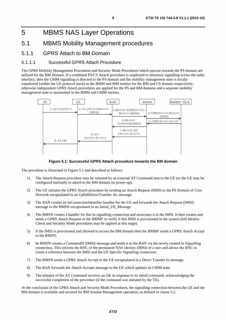
Figure 5.1: Successful GPRS Attach procedure towards the BM domain
The procedure is illustrated in Figure 5.1 and described as follows:
1) The Attach Request procedure may be initiated by an external AT Command sent to the UE (or the UE may be configured internally to attach to the BM domain on power-up).
2) The UE initiates the GPRS Attach procedure by sending an Attach Request (IMSI) to the PS Domain of Core Network encapsulated in an UplinkDirectTransfer AL message.
3) The RAN creates an IuConnectionIdentifier handler for the UE and forwards the Attach Request (IMSI) message to the BMSN encapsulated in an Initial_UE_Message.
4) The BMSN creates a handler for this Iu signalling connection and associates it to the IMSI. It then creates and sends a GPRS Attach Request to the BMMF to verify if this IMSI is provisioned in the system (full Identity Check and Security Mode procedures may be applied at this stage).
5) If the IMSI is provisioned and allowed to access the BM domain then the BMMF sends a GPRS Attach Accept to the BMSN.
6) he BMSN creates a CommonID (IMSI) message and sends it to the RAN via the newly created Iu Signalling connection. This informs the RNC of the permanent NAS identity (IMSI) of a user and allows the RNC to create a reference between the IMSI and the UE Specific Signalling connection.
7) The BMSN sends a GPRS Attach Accept to the UE encapsulated in a Direct Transfer Iu message.
8) The RAN forwards the Attach Accepts message to the UE which updates its GMM state.
9) The initiator of the AT Command receives an OK in response to its initial command, acknowledging the successful completion of the procedure (if the command was initiated by the TE).
At the conclusion of the GPRS Attach and Security Mode Procedures, the signalling connection between the UE and the BM domain is available and secured for BM Session Management operation, as defined in clause 5.2.
BMMF/ HLR TE UE RAN BMSN
2. UDT (ATTACH REQUEST
(IMSI)) 1. AT+CGATT=1 3. BRANAP : IUEM ( ATTACH
REQUEST (IMSI)) 4. GPRS ATTACH REQUEST
(IMSI) 5. GPRS A TTACH ACCEPT
8. DDT: (ATTACH ACCEPT)
9. AT: OK
6. BRANAP : COMMONID (IMSI)
7. BRANAP: DT (ATTACH ACCEPT)
ETSI
ETSI TS 102 744-3-8 V1.1.1 (2015-10) 10
5.1.1.2 Unsuccessful GPRS Attach Procedure
An unsuccessful GPRS Attach procedure may occur for a number of reasons, including:
1) The IMSI for the UE is not provisioned for operation with the BM domain;
2) Security mode procedures fail;
3) Communications within the Access Stratum are unreliable.
Until the GPRS Attach Procedure towards the BM succeeds (or a Combined Attach procedure succeeds), no further BMSM signalling can take place.
5.1.2 GPRS Detach
5.1.2.0 General
The GPRS Detach procedure may be initiated by either the User Equipment or the Core Network to remove the mobility management association between the UE and the CN.
5.1.2.1 CN-initiated GPRS Detach Request
If the UE was attached to multiple domains using a combined Attach procedure, a GPRS Detach procedure initiated by any of the Core Network domains will result in loss of connectivity between the UE and all Core Network Domains, including the BM Domain.
If the UE utilized a specific Attach procedure towards the BM domain, then the UE shall only modify the mobility management state held in the BMM entity in response to a GPRS Detach procedure initiated by the BM domain,
Upon reception of a GPRS Detach Request initiated by the BM Domain of the Core Network, the UE shall acknowledge the Detach Request to the BM Domain. All PDP Context information shall be implicitly deleted by both the UE and the CN, and all RABs shall be considered implicitly deleted by the UE. The CN shall issue an IuSignalling Connection Release Request, and all RABs shall be considered implicitly deleted by the RAN.
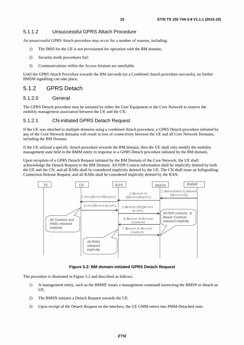
Figure 5.2: BM domain-initiated GPRS Detach Request
The procedure is illustrated in Figure 5.2 and described as follows:
1) A management entity, such as the BMMF issues a management command instructing the BMSN to detach an UE.
2) The BMSN initiates a Detach Request towards the UE.
3) Upon receipt of the Detach Request on the interface, the UE GMM enters into PMM-Detached state.
TE UE RAN
4. UDT (D ETACH ACCEPT) 5. BRANAP: DT (D ETACH
ACCEPT)
BMSN
2. BRANAP: DT (DETACH REQUEST) 3. DDT: (D ETACH REQUEST)
6. BRANAP: I U RELEASE
COMMAND
7. BRANAP : I U RELEASE
COMPLETE
BMMF
1. MANAGEMENT COMMAND (DETACH UE)
All RABs released impli citly
All Contexts and RABs released implicitly
All PDP contexts & Bearer Contexts released implicitly
ETSI
ETSI TS 102 744-3-8 V1.1.1 (2015-10) 11
4) The UE deletes all connection state and responds to the BMSN by forwarding a Detach_Accept message via the RAN encapsulated in an Uplink Direct Transfer message.
5) The RAN sends this NAS message to the BMSN via the IuBM interface in a Direct Transfer Iu container.
6) The BMSN initiates an Iu Release Command to remove the UE-specific signalling connection between the RAN and the PS domain of the CN.
7) The RNC implicitly releases all RABs and completes the Iu Release command.
5.1.2.2 UE-initiated GPRS Detach Request
If the UE utilized a combined Attach procedure, then the Detach procedure will be directed to the PS domain.
If the UE utilized a specific Attach procedure to obtain access to the BM domain, then the UE shall initiate a specific GPRS Detach procedure towards the BM domain.
All connection states within the UE are deleted implicitly.
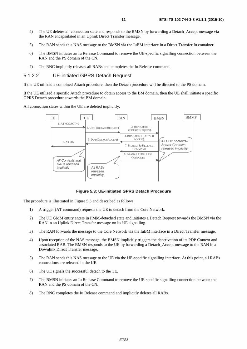
Figure 5.3: UE-initiated GPRS Detach Procedure
The procedure is illustrated in Figure 5.3 and described as follows:
1) A trigger (AT command) requests the UE to detach from the Core Network.
2) The UE GMM entity enters in PMM-detached state and initiates a Detach Request towards the BMSN via the RAN in an Uplink Direct Transfer message on its UE signalling.
3) The RAN forwards the message to the Core Network via the IuBM interface in a Direct Transfer message.
4) Upon reception of the NAS message, the BMSN implicitly triggers the deactivation of its PDP Context and associated RAB. The BMSN responds to the UE by forwarding a Detach_Accept message to the RAN in a Downlink Direct Transfer message.
5) The RAN sends this NAS message to the UE via the UE-specific signalling interface. At this point, all RABs connections are released in the UE.
6) The UE signals the successful detach to the TE.
7) The BMSN initiates an Iu Release Command to remove the UE-specific signalling connection between the RAN and the PS domain of the CN.
8) The RNC completes the Iu Release command and implicitly deletes all RABs.
All RABs released implicitly
All Contexts and RABs released implicitly
All PDP contexts & Bearer Contexts released implicitly
6. AT
OK
TE UE RAN
5. D DT (DETACH A CCEPT)
4. BRANAP:
DT
(DETACH
A CCEPT)
BM SN
3. BRANAP: DT
(D ETACH R EQUEST) 2.
U DT:
(DETACH REQUEST)
7 . BRANAP :
I U R ELEASE
COMMAND 8.
BRANAP :
IU RELEASE
COMPLETE
BMMF 1.
AT+CGACT=0
ETSI
ETSI TS 102 744-3-8 V1.1.1 (2015-10) 12
5.2 MBMS Service Management Procedures
5.2.1 MBMS Service Activation
5.2.1.0 General
MBMS Services are delivered to UEs using MBMS Radio Access Bearers established during the MBMS Context activation procedure.
Whenever it is necessary to deliver a MBMS Service to a UE, the MBMS Context Activation procedure will be initiated at the UE, either by an external trigger or by a Request from the BMSN. In the former case, it is required that the external control entity has a-priori knowledge of the MBMS Temporary Multicast Group Identifier (TMGI) as it shall be signalled in the request from the Terminal Equipment (TE) using the appropriate AT Command.
5.2.1.1 MBMS Context Activation
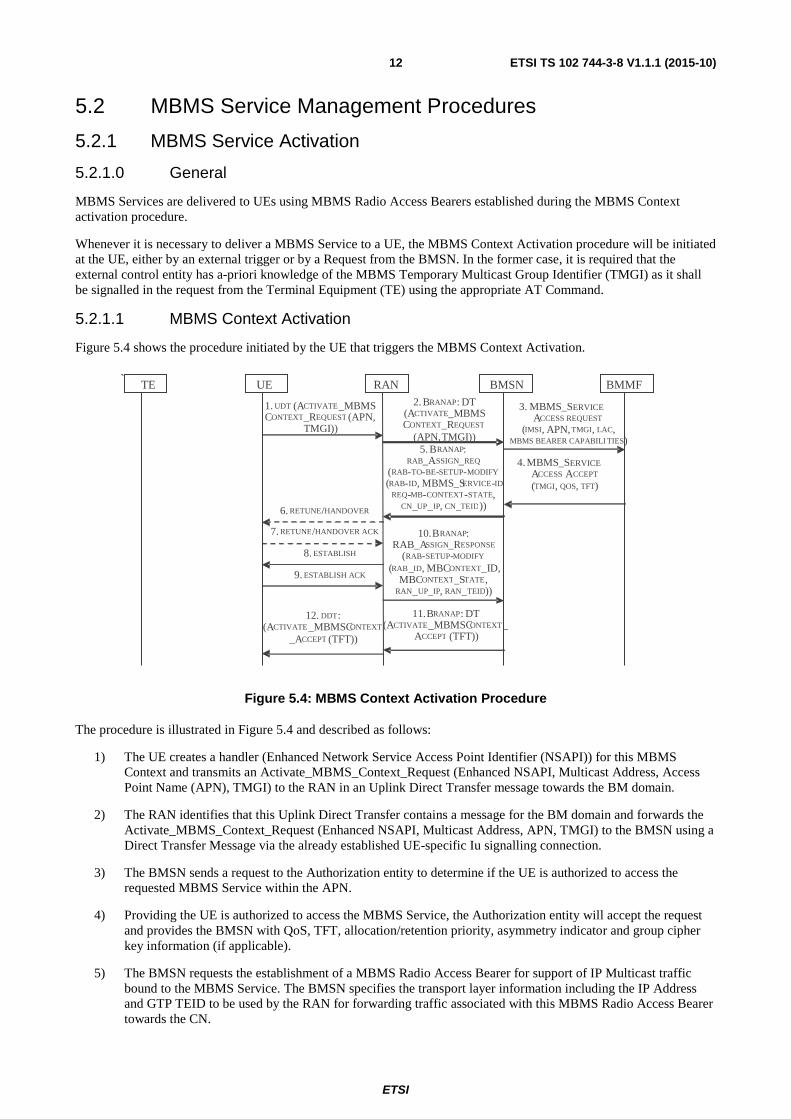
Figure 5.4 shows the procedure initiated by the UE that triggers the MBMS Context Activation.
Figure 5.4: MBMS Context Activation Procedure
The procedure is illustrated in Figure 5.4 and described as follows:
1) The UE creates a handler (Enhanced Network Service Access Point Identifier (NSAPI)) for this MBMS Context and transmits an Activate_MBMS_Context_Request (Enhanced NSAPI, Multicast Address, Access Point Name (APN), TMGI) to the RAN in an Uplink Direct Transfer message towards the BM domain.
2) The RAN identifies that this Uplink Direct Transfer contains a message for the BM domain and forwards the Activate_MBMS_Context_Request (Enhanced NSAPI, Multicast Address, APN, TMGI) to the BMSN using a Direct Transfer Message via the already established UE-specific Iu signalling connection.
3) The BMSN sends a request to the Authorization entity to determine if the UE is authorized to access the requested MBMS Service within the APN.
4) Providing the UE is authorized to access the MBMS Service, the Authorization entity will accept the request and provides the BMSN with QoS, TFT, allocation/retention priority, asymmetry indicator and group cipher key information (if applicable).
5) The BMSN requests the establishment of a MBMS Radio Access Bearer for support of IP Multicast traffic bound to the MBMS Service. The BMSN specifies the transport layer information including the IP Address and GTP TEID to be used by the RAN for forwarding traffic associated with this MBMS Radio Access Bearer towards the CN.
` BMMF TE UE RAN BMSN
1. UDT (ACTIVATE_MBMS CONTEXT_REQUEST (APN,
TMGI))
2. BRANAP: DT (ACTIVATE_MBMS CONTEXT_REQUEST
(APN, TMGI))
3. MBMS_SERVICE ACCESS REQUEST
(IMSI, APN, TMGI, LAC , MBMS BEARER CAPABILI TIES)
4. MBMS_SERVICE ACCESS ACCEPT (TMGI, QOS, TFT)
11. BRANAP : DT (A CTIVATE_MBMSCONTEXT_
ACCEPT (TFT))
12. DDT: (A CTIVATE _MBMSCONTEXT
_A CCEPT (TFT))
10. BRANAP: RAB_A SSIGN_RESPONSE
(RAB- SETUP-MODIFY (RAB_ID, MBCONTEXT_ID,
MBCONTEXT_STATE, RAN _UP _IP, RAN_TEID))
8. ESTABLISH
9. ESTABLISH ACK
6. RETUNE/HANDOVER 7. RETUNE/HANDOVER ACK
5. BRANAP: RAB_A SSIGN_REQ
(RAB- TO- BE-SETUP- MODIFY ( RAB- ID, MBMS_SERVICE- ID
REQ - MB-CONTEXT- STATE, CN_UP _IP, CN_TEID))
ETSI
ETSI TS 102 744-3-8 V1.1.1 (2015-10) 13
6) At reception of the RAB Assignment Request, the RAN determines whether there is sufficient capacity to support the MBMS Radio Access Bearer QoS requirements, and if necessary triggers a Retune or Handover procedure.
7) Upon reception of the Retune or Handover message the UE acknowledges the Retune or Handover message
8) The RAN then sends an Establish message to associate the UE with the MBMS Radio Access Bearer.
9) The UE acknowledges the association using an EstablishAck message.
10) The RAN confirms that the MBMS Radio Access Bearer has been successfully established, and provides a reference to the MBMS Context (using an RNC GTPu IP Address and RNC GTP Tunnel Endpoint Identifier as a reference) with which the UE is associated using a RAB Assignment Response. The RAN provides the CN with the MBMS Context ID with which the MBMS Radio Access Bearer is associated. If this is a newly created MBMS Context ID, the value of the MBMS Context State information element will indicate that the RNC is waiting to be configured with the MBMS Context State by the CN. If the MBMS Radio Access Bearer is associated with an existing MBMS Context, then the MBMS Context State information will reflect the current MBMS Context State of the associated MBMS Context.
11) The BMSN completes the NAS transaction by sending an Activate_MBMS_Context_Accept(TMGI, TFT) message to the UE in a Direct Transfer message via the UE-specific Iu signalling connection with the RAN. If the required IP multicast group/source is not currently being received by the BMSN, then the BMSN generates a Protocol Independent Multicast - Session Management (PIM-SM) join message towards the upstream routers, rendezvous point or multicast source.
12) The RAN forwards the Activate_MBMS_Context_Accept(TMGI) towards the UE in a DownlinkDataTransfer message via the UE-specific-signalling connection.
5.2.1.2 CN-initiated MBMS Context Activation
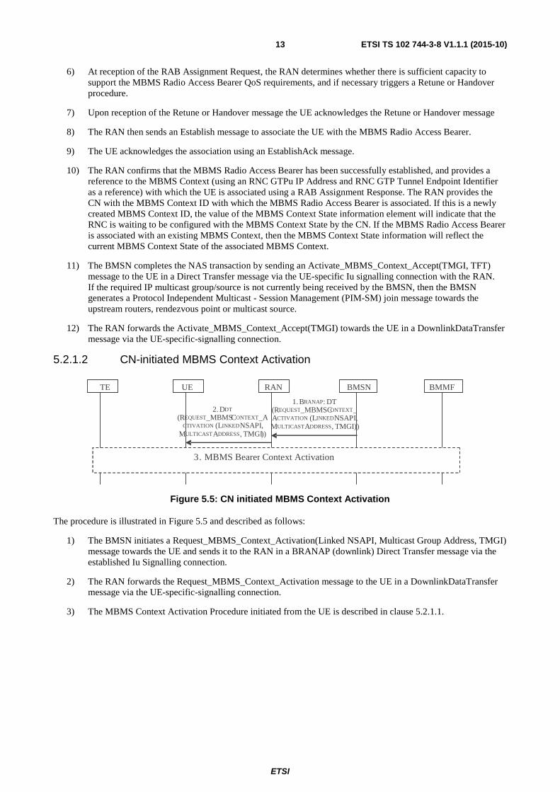
Figure 5.5: CN initiated MBMS Context Activation
The procedure is illustrated in Figure 5.5 and described as follows:
1) The BMSN initiates a Request_MBMS_Context_Activation(Linked NSAPI, Multicast Group Address, TMGI) message towards the UE and sends it to the RAN in a BRANAP (downlink) Direct Transfer message via the established Iu Signalling connection.
2) The RAN forwards the Request_MBMS_Context_Activation message to the UE in a DownlinkDataTransfer message via the UE-specific-signalling connection.
3) The MBMS Context Activation Procedure initiated from the UE is described in clause 5.2.1.1.
BMMF TE UE RAN BMSN
1. BRANAP: DT (REQUEST_MBMSCONTEXT_ ACTIVATION
( LINKED NSAPI, MULTICASTA DDRESS , TMGI))
2. DDT
(REQUEST_MBMSCONTEXT_ACTIVATION ( L INKED NSAPI,
MULTICAST ADDRESS, TMGI ))
3. MBMS Bearer Context Activation

ETSI
ETSI TS 102 744-3-8 V1.1.1 (2015-10) 14
5.2.1.3 Unsuccessful MBMS Context Activation (Service not authorized)
Figure 5.6: Unsuccessful MBMS Context Activation- Service not authorized
The procedure is illustrated in Figure 5.6 and described as follows. Transactions 1 to 3 are described in clause 5.2.1.1.
1) The Authorization entity determines that the UE is not authorized to access the MBMS Service (TMGI) and responds to the request with a MBMS_Service_Access_Reject(cause).
2) The BMSN informs the UE that the MBMS Context cannot be activated and specify the cause. The message is sent to the RAN in a Direct Transfer message on the Iu interface.
3) The RAN forwards the NAS message to the UE. The UE destroys the handler for this MBMS Context.
5.2.1.4 Unsuccessful MBMS Context activation (Critical failure or Layer 2 establishment rejection)
Figure 5.7 shows the same initial transactions for activation of the MBMS Context described in clause 5.2.1.1 with the difference that a critical failure occurs during L2 establishment and the UE fails to complete its Establish procedure (transaction 9 on Figure 5.7).
Figure 5.7: MRAB establishment Failed - Layer 2 failure
1) The RAN informs the BMSN that the MRAB establishment was unsuccessful (RAB failed to establish).
2) The BMSN builds an Activate_MBMS_Context_Reject and sends it to the UE via the RAN. No further action is required from the BMSN.
3) The RAN forwards the NAS message to the UE to inform it that the MBMS Context activation procedure has failed. The UE destroys it MBMS Context handler.
ETSI
ETSI TS 102 744-3-8 V1.1.1 (2015-10) 15
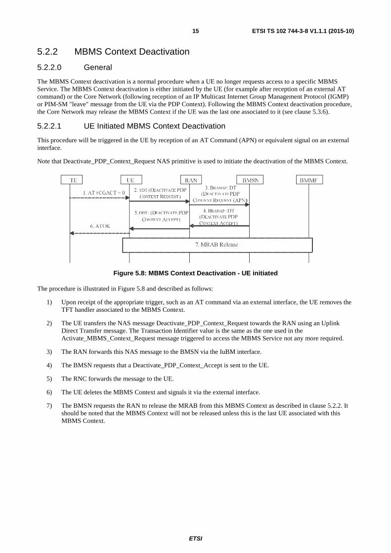
5.2.2 MBMS Context Deactivation
5.2.2.0 General
The MBMS Context deactivation is a normal procedure when a UE no longer requests access to a specific MBMS Service. The MBMS Context deactivation is either initiated by the UE (for example after reception of an external AT command) or the Core Network (following reception of an IP Multicast Internet Group Management Protocol (IGMP) or PIM-SM "leave" message from the UE via the PDP Context). Following the MBMS Context deactivation procedure, the Core Network may release the MBMS Context if the UE was the last one associated to it (see clause 5.3.6).
5.2.2.1 UE Initiated MBMS Context Deactivation
This procedure will be triggered in the UE by reception of an AT Command (APN) or equivalent signal on an external interface.
Note that Deactivate_PDP_Context_Request NAS primitive is used to initiate the deactivation of the MBMS Context.
Figure 5.8: MBMS Context Deactivation - UE initiated
The procedure is illustrated in Figure 5.8 and described as follows:
1) Upon receipt of the appropriate trigger, such as an AT command via an external interface, the UE removes the TFT handler associated to the MBMS Context.
2) The UE transfers the NAS message Deactivate_PDP_Context_Request towards the RAN using an Uplink Direct Transfer message. The Transaction Identifier value is the same as the one used in the Activate_MBMS_Context_Request message triggered to access the MBMS Service not any more required.
3) The RAN forwards this NAS message to the BMSN via the IuBM interface.
4) The BMSN requests that a Deactivate_PDP_Context_Accept is sent to the UE.
5) The RNC forwards the message to the UE.
6) The UE deletes the MBMS Context and signals it via the external interface.
7) The BMSN requests the RAN to release the MRAB from this MBMS Context as described in clause 5.2.2. It should be noted that the MBMS Context will not be released unless this is the last UE associated with this MBMS Context.
ETSI
ETSI TS 102 744-3-8 V1.1.1 (2015-10) 16
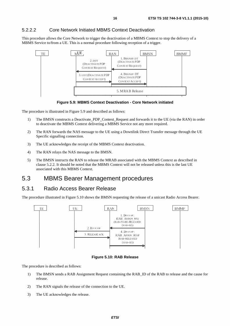
5.2.2.2 Core Network Initiated MBMS Context Deactivation
This procedure allows the Core Network to trigger the deactivation of a MBMS Context to stop the delivery of a MBMS Service to/from a UE. This is a normal procedure following reception of a trigger.
Figure 5.9: MBMS Context Deactivation - Core Network initiated
The procedure is illustrated in Figure 5.9 and described as follows:
1) The BMSN constructs a Deactivate_PDP_Context_Request and forwards it to the UE (via the RAN) in order to deactivate the MBMS Context delivering a MBMS Service not any more required.
2) The RAN forwards the NAS message to the UE using a Downlink Direct Transfer message through the UE Specific signalling connection.
3) The UE acknowledges the receipt of the MBMS Context deactivation.
4) The RAN relays the NAS message to the BMSN.
5) The BMSN instructs the RAN to release the MRAB associated with the MBMS Context as described in clause 5.2.2. It should be noted that the MBMS Context will not be released unless this is the last UE associated with this MBMS Context.
5.3 MBMS Bearer Management procedures
5.3.1 Radio Access Bearer Release
The procedure illustrated in Figure 5.10 shows the BMSN requesting the release of a unicast Radio Access Bearer.
Figure 5.10: RAB Release
The procedure is described as follows:
1) The BMSN sends a RAB Assignment Request containing the RAB_ID of the RAB to release and the cause for release.
2) The RAN signals the release of the connection to the UE.
3) The UE acknowledges the release.
BMMF TE MT RAN
3. UDT (DEACTIVATE PDP
CONTEXT ACCEPT)
4. BRANAP: DT (DEACTIVATE PDP
CONTEXT ACCEPT)
1. BRANAP: DT (DEACTIVATE PDP
CONTEXT REQUEST)
2. DDT (DEACTIVATE PDP
CONTEXT REQUEST)
5. MRAB Release
BMSN UE
ETSI
ETSI TS 102 744-3-8 V1.1.1 (2015-10) 17
4) The RAN confirms the release of the Radio Access Bearer to the BMSN.
Note that the BMSN may request the release of more than one RAB in a single RAB Assignment Request primitive. Transactions 2, 3 and 5 would repeated for each RAB.
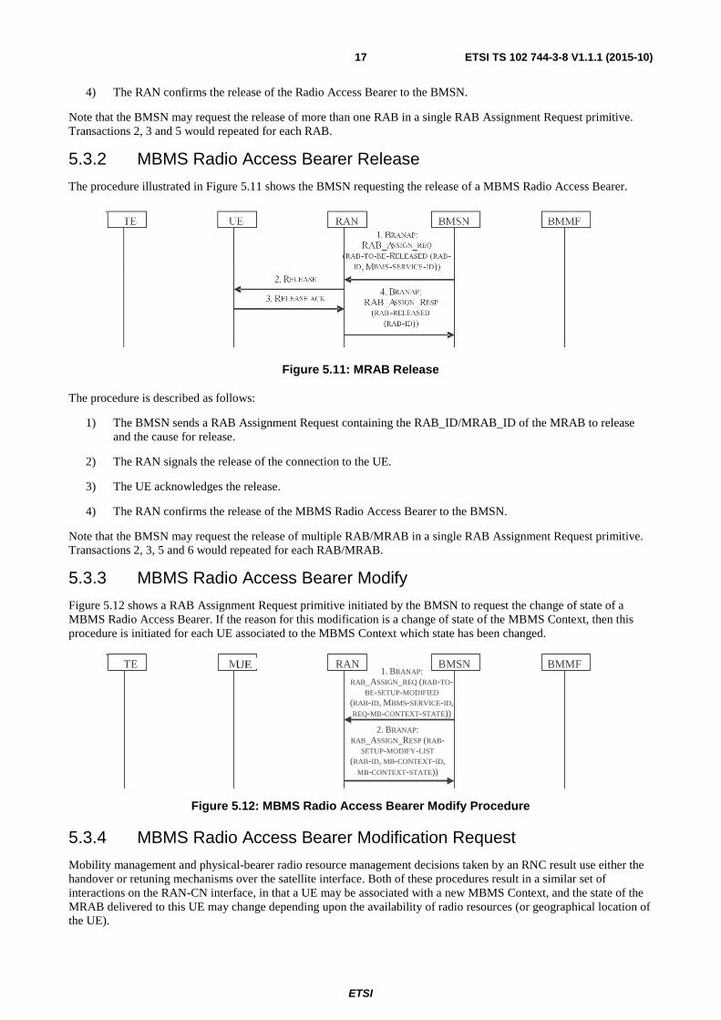
5.3.2 MBMS Radio Access Bearer Release
The procedure illustrated in Figure 5.11 shows the BMSN requesting the release of a MBMS Radio Access Bearer.
Figure 5.11: MRAB Release
The procedure is described as follows:
1) The BMSN sends a RAB Assignment Request containing the RAB_ID/MRAB_ID of the MRAB to release and the cause for release.
2) The RAN signals the release of the connection to the UE.
3) The UE acknowledges the release.
4) The RAN confirms the release of the MBMS Radio Access Bearer to the BMSN.
Note that the BMSN may request the release of multiple RAB/MRAB in a single RAB Assignment Request primitive. Transactions 2, 3, 5 and 6 would repeated for each RAB/MRAB.
5.3.3 MBMS Radio Access Bearer Modify
Figure 5.12 shows a RAB Assignment Request primitive initiated by the BMSN to request the change of state of a MBMS Radio Access Bearer. If the reason for this modification is a change of state of the MBMS Context, then this procedure is initiated for each UE associated to the MBMS Context which state has been changed.
Figure 5.12: MBMS Radio Access Bearer Modify Procedure
5.3.4 MBMS Radio Access Bearer Modification Request
Mobility management and physical-bearer radio resource management decisions taken by an RNC result use either the handover or retuning mechanisms over the satellite interface. Both of these procedures result in a similar set of interactions on the RAN-CN interface, in that a UE may be associated with a new MBMS Context, and the state of the MRAB delivered to this UE may change depending upon the availability of radio resources (or geographical location of the UE).
` BMMF TE MT RAN 1. BRANAP:
RAB_ASSIGN_REQ (RAB-TO-BE-SETUP-MODIFIED
(RAB-ID, MBMS-SERVICE-ID, REQ-MB-CONTEXT-STATE))
2. BRANAP: RAB_ASSIGN_RESP (RAB-
SETUP-MODIFY-LIST (RAB-ID, MB-CONTEXT-ID,
MB-CONTEXT-STATE))
BMSN UE
ETSI
ETSI TS 102 744-3-8 V1.1.1 (2015-10) 18
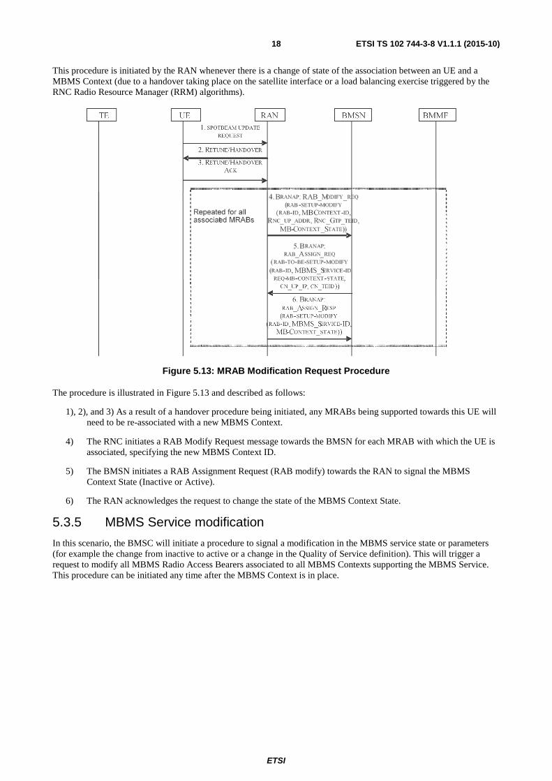
This procedure is initiated by the RAN whenever there is a change of state of the association between an UE and a MBMS Context (due to a handover taking place on the satellite interface or a load balancing exercise triggered by the RNC Radio Resource Manager (RRM) algorithms).
Figure 5.13: MRAB Modification Request Procedure
The procedure is illustrated in Figure 5.13 and described as follows:
1), 2), and 3) As a result of a handover procedure being initiated, any MRABs being supported towards this UE will need to be re-associated with a new MBMS Context.
4) The RNC initiates a RAB Modify Request message towards the BMSN for each MRAB with which the UE is associated, specifying the new MBMS Context ID.
5) The BMSN initiates a RAB Assignment Request (RAB modify) towards the RAN to signal the MBMS Context State (Inactive or Active).
6) The RAN acknowledges the request to change the state of the MBMS Context State.
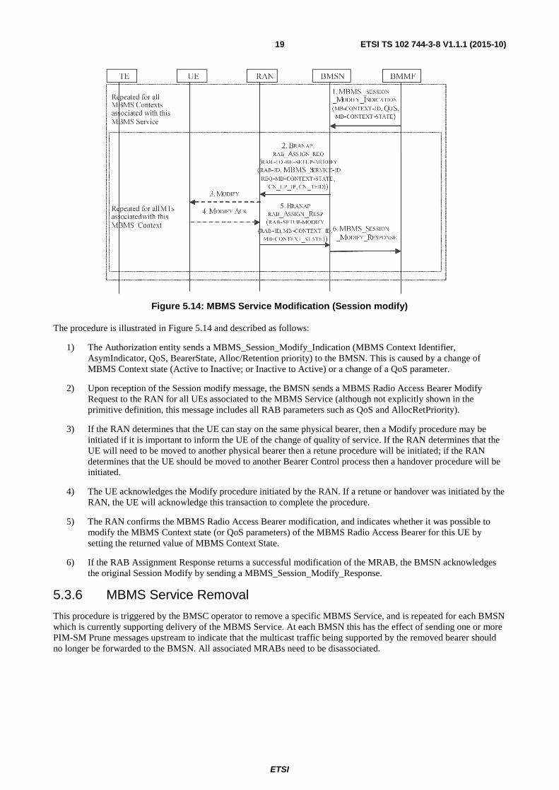
5.3.5 MBMS Service modification
In this scenario, the BMSC will initiate a procedure to signal a modification in the MBMS service state or parameters (for example the change from inactive to active or a change in the Quality of Service definition). This will trigger a request to modify all MBMS Radio Access Bearers associated to all MBMS Contexts supporting the MBMS Service. This procedure can be initiated any time after the MBMS Context is in place.
ETSI
ETSI TS 102 744-3-8 V1.1.1 (2015-10) 19
Figure 5.14: MBMS Service Modification (Session modify)
The procedure is illustrated in Figure 5.14 and described as follows:
1) The Authorization entity sends a MBMS_Session_Modify_Indication (MBMS Context Identifier, AsymIndicator, QoS, BearerState, Alloc/Retention priority) to the BMSN. This is caused by a change of MBMS Context state (Active to Inactive; or Inactive to Active) or a change of a QoS parameter.
2) Upon reception of the Session modify message, the BMSN sends a MBMS Radio Access Bearer Modify Request to the RAN for all UEs associated to the MBMS Service (although not explicitly shown in the primitive definition, this message includes all RAB parameters such as QoS and AllocRetPriority).
3) If the RAN determines that the UE can stay on the same physical bearer, then a Modify procedure may be initiated if it is important to inform the UE of the change of quality of service. If the RAN determines that the UE will need to be moved to another physical bearer then a retune procedure will be initiated; if the RAN determines that the UE should be moved to another Bearer Control process then a handover procedure will be initiated.
4) The UE acknowledges the Modify procedure initiated by the RAN. If a retune or handover was initiated by the RAN, the UE will acknowledge this transaction to complete the procedure.
5) The RAN confirms the MBMS Radio Access Bearer modification, and indicates whether it was possible to modify the MBMS Context state (or QoS parameters) of the MBMS Radio Access Bearer for this UE by setting the returned value of MBMS Context State.
6) If the RAB Assignment Response returns a successful modification of the MRAB, the BMSN acknowledges the original Session Modify by sending a MBMS_Session_Modify_Response.
5.3.6 MBMS Service Removal
This procedure is triggered by the BMSC operator to remove a specific MBMS Service, and is repeated for each BMSN which is currently supporting delivery of the MBMS Service. At each BMSN this has the effect of sending one or more PIM-SM Prune messages upstream to indicate that the multicast traffic being supported by the removed bearer should no longer be forwarded to the BMSN. All associated MRABs need to be disassociated.

ETSI
ETSI TS 102 744-3-8 V1.1.1 (2015-10) 20
Figure 5.15: MBMS Service removal
The procedure is illustrated in Figure 5.15 and described as follows:
1) A MBMS_Bearer_Context_Deregister_Indication(TMGI) is sent from the Authorization entity to the BMSN.
2) The BMSN responds immediately with a MBMS_Bearer_Context_Deregister_Response.
3) The BMSN sends a PIM-SM Prune messages upstream to indicate that the multicast flows supported by the removed bearer are no longer required to be delivered to the BMSN.
4) The BMSN shall initiate a MBMS Context Deactivation procedure as defined in clause 5.2.2.2 for each UE associated with this MBMS Service.
6 Mobility Management Behaviour
6.1 Spot Beam Handover Spot-beam handover procedures occur as a consequence of a UE transition across a spot-beam boundary. The UE is responsible for determining when such a transition has occurred, by comparing its current location, derived from GPS navigation information, with the spot-beam maps received from the RAN in System Information broadcasts. When a transition is determined to have occurred, the UE will signal the requirement for a handover to occur, at which point the RNC will execute the Handover procedure as defined in clause 5.3.4 of ETSI TS 102 744-3-2 [4].
For unicast bearer services, no interaction with the PS or BM domain of the Core Network would normally occur during the Handover procedure unless a unicast RAB cannot be supported on the new physical bearer due to resource constraints. This would be an exception condition that would cause termination of the RAB. If the RAB is maintained, there will be no significant change in the resource requirements, and the Core Network is not informed immediately. It should be noted however, that a Location Update procedure may be triggered as a consequence of receiving updated Location Area Identifier in the bulletin board of the new beam - this procedure would therefore occurs after the Handover has completed.
For MBMS services, an interaction with the BM is required, as MBMS services may be constrained to operate only in specific beams, or to operate with a maximum number of MBMS Contexts, and due to the shared nature of the resources, a significant change in resource requirements may occur as a consequence of handover taking place.
During the Handover of an UE supporting a MBMS Service, the UE will be reassociated with a new MBMS Connection. If a suitable MBMS Connection is in existence, then the RNC will signal the change of state of the RAB towards the UE using an MRAB Modify Request procedure towards the CN as defined in clause 5.3.4, signalling both the MBMS Context that is being used to support the UE, and reflecting the MRAB-state of the MBMS Context with which the UE is now associated. The CN may not need to take further action at this point, beyond indicating the update the accounting call data records for the UE and the MBMS Contexts.
ETSI
ETSI TS 102 744-3-8 V1.1.1 (2015-10) 21
If a suitable MBMS Connection does not exist, the RNC will create a new MBMS Connection, set the MRAB-state to Inactive, and once again undertake the MRAB Modify Request procedure towards the CN as defined in clause 5.3.4. As a consequence of this event taking place, the BMSN will determine from the Broadcast Multicast Service Centre (BMSC) whether the MBMS Context may be placed in an Active state, and if so will execute the RAB Modify (change of state) procedure as defined in clause 5.3.3.
6.2 Inter-RNC operation (via different satellites) No direct support for mobility between satellites is provided, and is this is true of both the PS and BM domains. However the multicast system does support the allocation of static IP addresses; and to simplify routing, the BMSN-router is deliberately separate from the BMSN-server functions, such that a global APN-specific BMSN-router (which may comprise a server farm in a high scalability network) may be defined, while the BMSN-router functions reside in each SAS site, communicating with the BMSCs via the central BMMF.
If an UE needs to move from one satellite to another, and can do so in a managed fashion, it should perform a GPRS Detach from the network on the 'serving' satellite, and reinitiate a GPRS Attach procedure with the network on the 'drift' satellite. This procedure will ensure that resources are released in the most expeditious fashion, however such a procedure is not always possible, and as a consequence exception conditions occur. These are handled at two levels in the BM domain:
a) MBMS Service status
b) UE status
Each MBMS Service may have an independent period for performing soft-state 'keep-alive' procedures, which comprise IGMP or PIM-SM behaviour as defined in clauses 8.2.2 and clause 8.3.4 respectively.
If services are activated by explicit control signalling, either by a control interface on the UE, or by the BMSC at initial PDP Context activation, then such maintenance soft-state procedures do not apply. In this case the UE status information is utilized, driven by the Inactivity timer operating in the RNC causing release of the Iu signalling connection.
6.3 Inter-system mobility This is outside the scope of this multi-part deliverable (Release 1) and is not covered in the present document.
7 Exception handling
7.1 Forced Detach (CN Initiated) An operator may forcibly detach an UE. When this occurs, the UE shall release the Primary PDP context from the BM domain.
7.2 Primary PDP Context deactivation (while MBMS Contexts present)
If the Primary PDP Context is released while a Secondary PDP context and/or a MBMS Context is still active, the BMSN shall explicitly delete all RABs associated with that Primary PDP context.
ETSI
ETSI TS 102 744-3-8 V1.1.1 (2015-10) 22
8 IP User Plane Handler for MBMS Services
8.0 General Requests to join and leave MBMS Services and resources allocation and release are driven by different triggers, which are defined in this clause.
8.1 UE-TE Controller triggered MBMS Services via R-interface
8.1.1 Activation of MBMS Services
Activation of MBMS Services using an externally triggered event is handled by the reception of an AT command via the R interface exactly as for unicast secondary PDP context activation. A primary PDP context shall be in existence and activated. The procedure requires that the external controller device is provisioned with the TMGI for referencing the specific MBMS Service. A result code will be returned to the external controller upon completion of the Multimedia Broadcast Multicast Service (MBMS) Context activation procedure. It should be noted that the active/inactive state of the MBMS Contexts used to deliver the service still remains the responsibility of the BMSC.
8.1.2 Deactivation of MBMS Services
If a MBMS Context is activated using an external controller, then the persistence of that MBMS Context is indefinite, and it is the responsibility of the external controller to deactivate the MBMS Context by issuing an appropriate AT command via the R interface. It should be noted that the BMSN shall ignore an IGMP membership report "leave" associated to the TMGI delivered through a MBMS Context activated using an external controller.
8.2 Directly Connected TEs - use of IGMP as a trigger
8.2.0 General
When TE devices are directly connected to the UE, MBMS Services may be activated or deactivated by issuance of IGMP membership reports as described in this clause. Maintenance of the services is controlled through the periodic transmission of BMSN-triggered IGMP membership query messages.
It should be noted that IP multicast sources in the mobile domain would normally utilize either the Primary or Secondary PDP context. However the use of a defined shared resource can be facilitated if there is a mapping between the group address utilized for the forward direction and that utilized for the return direction, so that the joining of multicast group by a receiver in the mobile domain can automatically trigger the activation of a bi-directional MBMS Context to support the return IP multicast traffic.
8.2.1 Joining and leaving multicast services
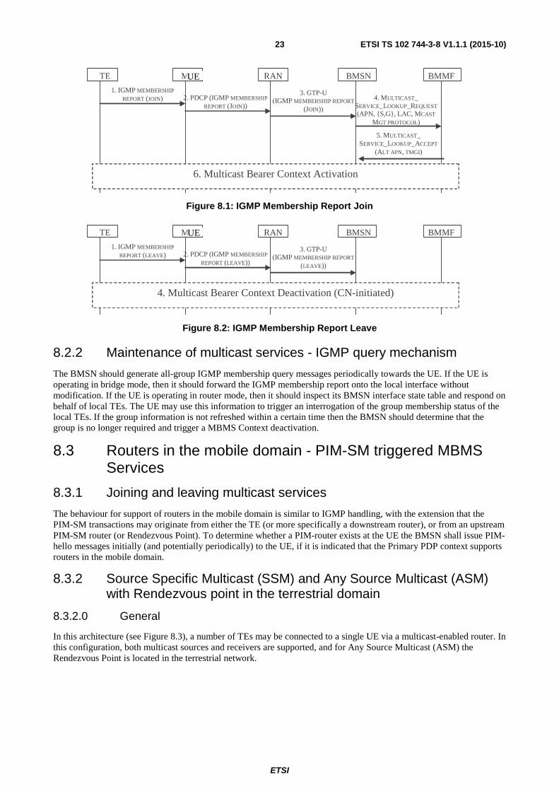
When an IGMP Membership Report is received on an interface to the UE, the UE shall perform the following decision making process, as illustrated in Figure 8.1 and Figure 8.2.
If the UE is configured with a local firewall, the firewall rules shall be inspected to determine whether the IGMP forwarding is allowed and whether the source is allowed to request the specified multicast group address or multicast channel.
If the IGMP membership report is allowed and the UE is operating in bridge mode, then the IGMP membership report shall be forwarded without modification towards the BMSN.
If the IGMP membership report is allowed and the UE is operating in router mode, with NAPT in operation, the BMSN shall determine whether the IGMP membership report results in a requirement for a new multicast group or multicast channel to be delivered to the UE, and if it does then the UE shall generate an IGMP membership report upstream to the BMSN using the PDP address and update the UE-BMSN interface state to include the requested group address or multicast channel. No further action is taken at this time by the UE.
Upon receipt of the IGMP membership report from the UE, the BMSN shall generate a Remote Authentication Dial In User Service (RADIUS) access request towards the BMSC (via the BMMF) to determine whether a suitable MBMS Service exists for which this UE has authorized access, and if this is the case then the TMGI is returned to the BMSN, which then triggers a MBMS Context Activation.
ETSI
ETSI TS 102 744-3-8 V1.1.1 (2015-10) 23
Figure 8.1: IGMP Membership Report Join
Figure 8.2: IGMP Membership Report Leave
8.2.2 Maintenance of multicast services - IGMP query mechanism
The BMSN should generate all-group IGMP membership query messages periodically towards the UE. If the UE is operating in bridge mode, then it should forward the IGMP membership report onto the local interface without modification. If the UE is operating in router mode, then it should inspect its BMSN interface state table and respond on behalf of local TEs. The UE may use this information to trigger an interrogation of the group membership status of the local TEs. If the group information is not refreshed within a certain time then the BMSN should determine that the group is no longer required and trigger a MBMS Context deactivation.
8.3 Routers in the mobile domain - PIM-SM triggered MBMS Services
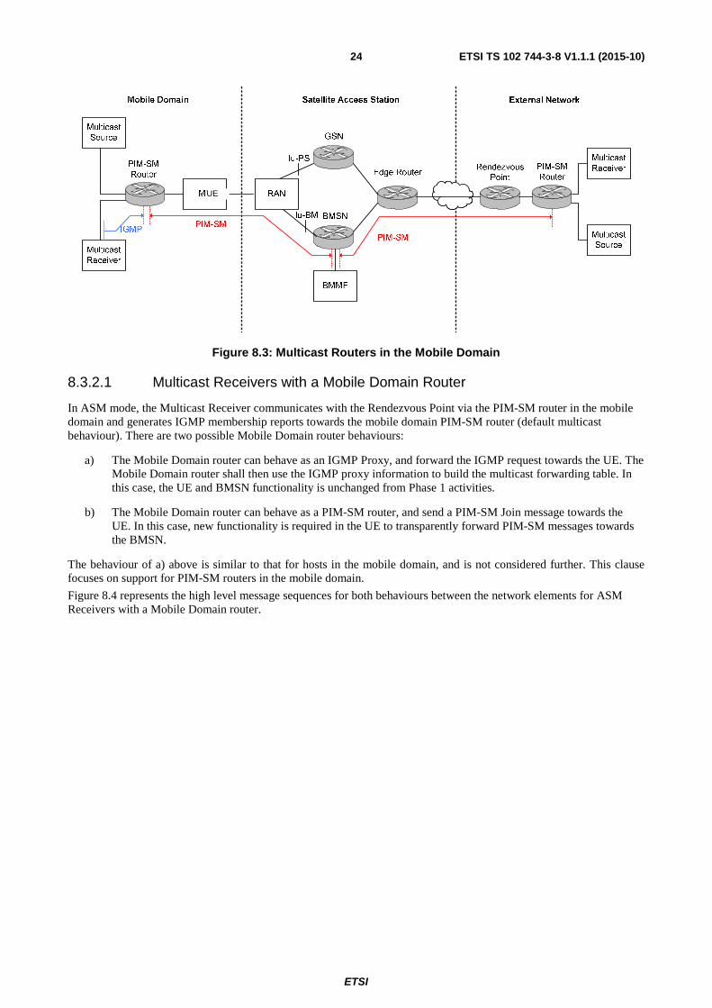
8.3.1 Joining and leaving multicast services
The behaviour for support of routers in the mobile domain is similar to IGMP handling, with the extension that the PIM-SM transactions may originate from either the TE (or more specifically a downstream router), or from an upstream PIM-SM router (or Rendezvous Point). To determine whether a PIM-router exists at the UE the BMSN shall issue PIM-hello messages initially (and potentially periodically) to the UE, if it is indicated that the Primary PDP context supports routers in the mobile domain.
8.3.2 Source Specific Multicast (SSM) and Any Source Multicast (ASM) with Rendezvous point in the terrestrial domain
8.3.2.0 General
In this architecture (see Figure 8.3), a number of TEs may be connected to a single UE via a multicast-enabled router. In this configuration, both multicast sources and receivers are supported, and for Any Source Multicast (ASM) the Rendezvous Point is located in the terrestrial network.
BMMF TE MT RAN BMSN
3. GTP-U (IGMP MEMBERSHIP REPORT
(JOIN))
2. PDCP (IGMP MEMBERSHIP
REPORT (JOIN))
6. Multicast Bearer Context Activation
1. IGMP MEMBERSHIP
REPORT (JOIN)
5. MULTICAST_ SERVICE_LOOKUP_ACCEPT
(ALT APN, TMGI)
4. MULTICAST_ SERVICE_LOOKUP_REQUEST
(APN, {S,G}, LAC, MCAST
MGT PROTOCOL)
UE
BMMF TE MT RAN BMSN
3. GTP-U (IGMP MEMBERSHIP REPORT
(LEAVE))
2. PDCP (IGMP MEMBERSHIP
REPORT (LEAVE))
4. Multicast Bearer Context Deactivation (CN-initiated)
1. IGMP MEMBERSHIP
REPORT (LEAVE)
UE
ETSI
ETSI TS 102 744-3-8 V1.1.1 (2015-10) 24
Figure 8.3: Multicast Routers in the Mobile Domain
8.3.2.1 Multicast Receivers with a Mobile Domain Router
In ASM mode, the Multicast Receiver communicates with the Rendezvous Point via the PIM-SM router in the mobile domain and generates IGMP membership reports towards the mobile domain PIM-SM router (default multicast behaviour). There are two possible Mobile Domain router behaviours:
a) The Mobile Domain router can behave as an IGMP Proxy, and forward the IGMP request towards the UE. The Mobile Domain router shall then use the IGMP proxy information to build the multicast forwarding table. In this case, the UE and BMSN functionality is unchanged from Phase 1 activities.
b) The Mobile Domain router can behave as a PIM-SM router, and send a PIM-SM Join message towards the UE. In this case, new functionality is required in the UE to transparently forward PIM-SM messages towards the BMSN.
The behaviour of a) above is similar to that for hosts in the mobile domain, and is not considered further. This clause focuses on support for PIM-SM routers in the mobile domain.
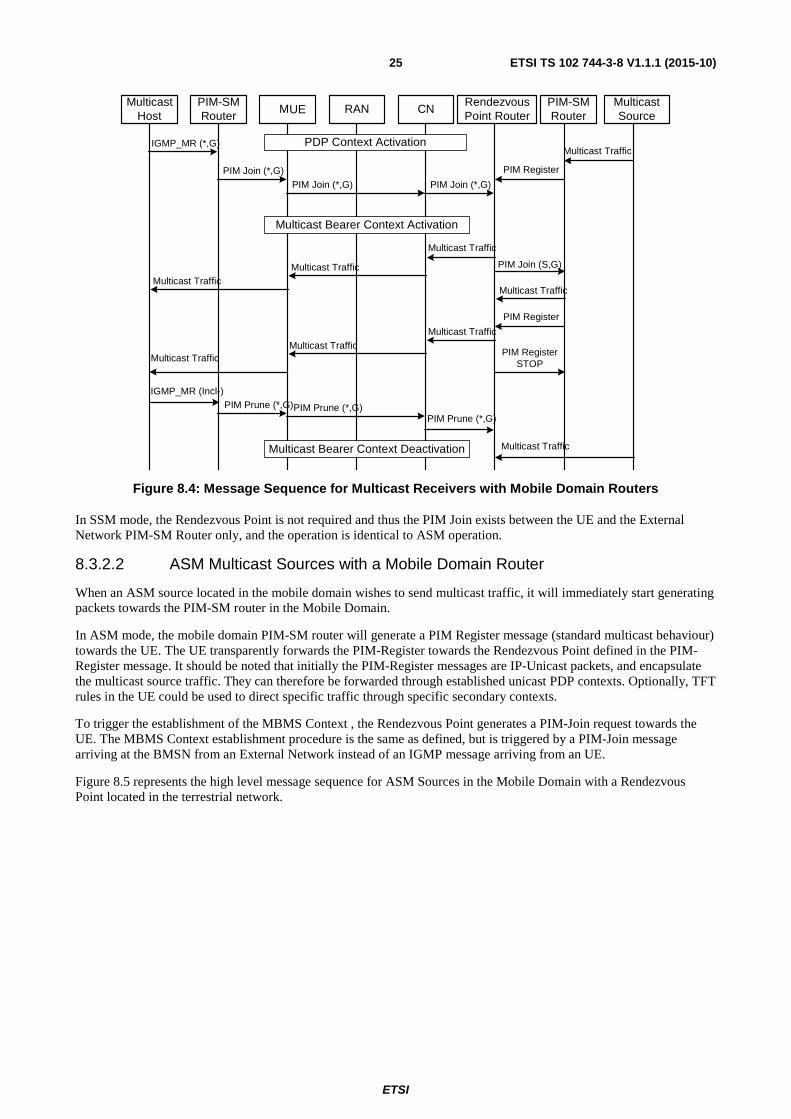
Figure 8.4 represents the high level message sequences for both behaviours between the network elements for ASM Receivers with a Mobile Domain router.
UE
ETSI
ETSI TS 102 744-3-8 V1.1.1 (2015-10) 25
Figure 8.4: Message Sequence for Multicast Receivers with Mobile Domain Routers
In SSM mode, the Rendezvous Point is not required and thus the PIM Join exists between the UE and the External Network PIM-SM Router only, and the operation is identical to ASM operation.
8.3.2.2 ASM Multicast Sources with a Mobile Domain Router
When an ASM source located in the mobile domain wishes to send multicast traffic, it will immediately start generating packets towards the PIM-SM router in the Mobile Domain.
In ASM mode, the mobile domain PIM-SM router will generate a PIM Register message (standard multicast behaviour) towards the UE. The UE transparently forwards the PIM-Register towards the Rendezvous Point defined in the PIM-Register message. It should be noted that initially the PIM-Register messages are IP-Unicast packets, and encapsulate the multicast source traffic. They can therefore be forwarded through established unicast PDP contexts. Optionally, TFT rules in the UE could be used to direct specific traffic through specific secondary contexts.
To trigger the establishment of the MBMS Context , the Rendezvous Point generates a PIM-Join request towards the UE. The MBMS Context establishment procedure is the same as defined, but is triggered by a PIM-Join message arriving at the BMSN from an External Network instead of an IGMP message arriving from an UE.
Figure 8.5 represents the high level message sequence for ASM Sources in the Mobile Domain with a Rendezvous Point located in the terrestrial network.
MulticastHost
PIM-SMRouter
MT RAN CNRendezvousPoint Router
PIM-SMRouter
MulticastSource
IGMP_MR (*,G)
PIM Register
Multicast Traffic
Multicast Traffic
PIM Join (S,G)
PIM Register
PIM RegisterSTOP
Multicast Traffic
Multicast Bearer Context Activation
PIM Join (*,G)
Multicast Traffic
Multicast Traffic
IGMP_MR (Incl-)
PIM Prune (*,G)
Multicast Traffic
Multicast TrafficMulticast Traffic
Multicast Traffic
PDP Context Activation
Multicast Bearer Context Deactivation
PIM Join (*,G)PIM Join (*,G)
PIM Prune (*,G)PIM Prune (*,G)
UE
ETSI
ETSI TS 102 744-3-8 V1.1.1 (2015-10) 26
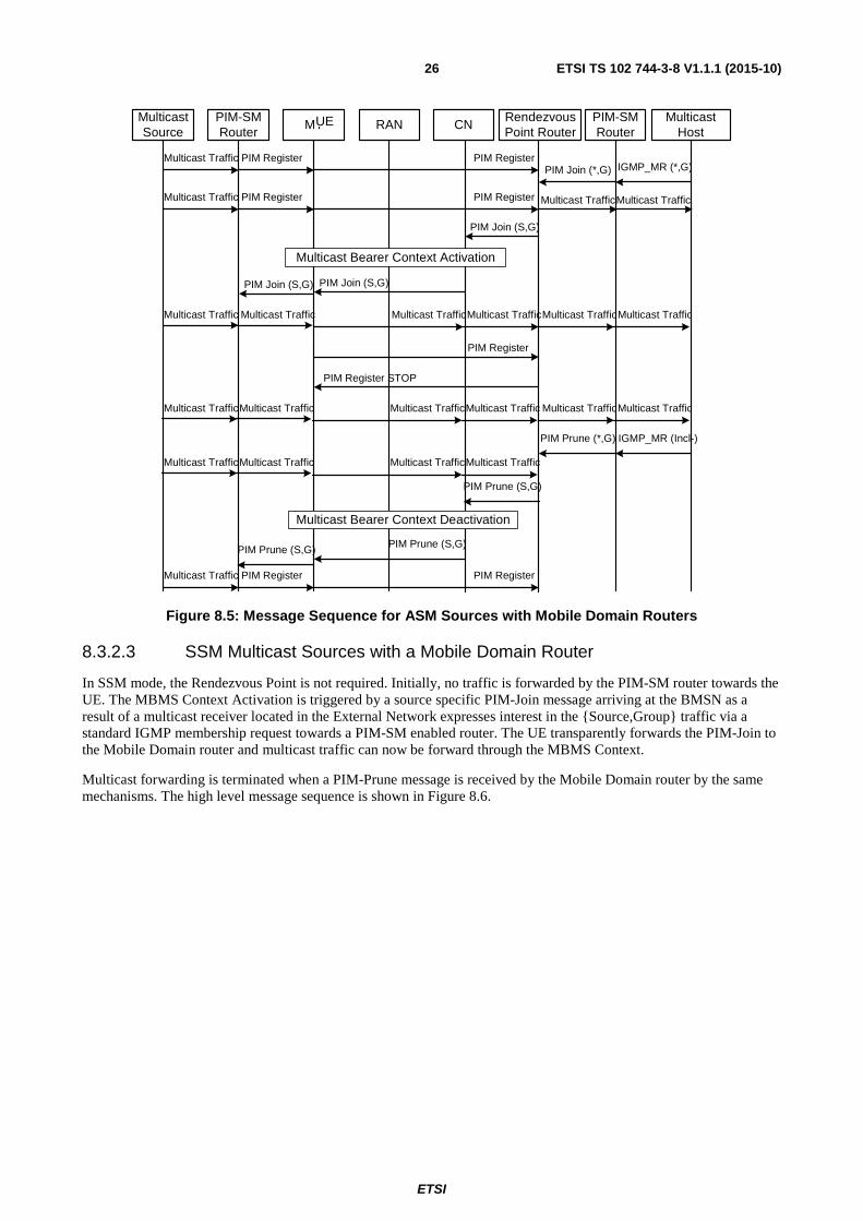
Figure 8.5: Message Sequence for ASM Sources with Mobile Domain Routers
8.3.2.3 SSM Multicast Sources with a Mobile Domain Router
In SSM mode, the Rendezvous Point is not required. Initially, no traffic is forwarded by the PIM-SM router towards the UE. The MBMS Context Activation is triggered by a source specific PIM-Join message arriving at the BMSN as a result of a multicast receiver located in the External Network expresses interest in the {Source,Group} traffic via a standard IGMP membership request towards a PIM-SM enabled router. The UE transparently forwards the PIM-Join to the Mobile Domain router and multicast traffic can now be forward through the MBMS Context.
Multicast forwarding is terminated when a PIM-Prune message is received by the Mobile Domain router by the same mechanisms. The high level message sequence is shown in Figure 8.6.
MulticastSource
PIM-SMRouter
MT RAN CNPIM-SMRouter
MulticastHost
Multicast Traffic
Multicast Bearer Context Activation
PIM Register PIM Register
PIM Join (S,G)
Multicast Traffic
PIM Register
PIM Register STOP
Multicast Traffic Multicast Traffic
RendezvousPoint Router
IGMP_MR (*,G)PIM Join (*,G)
Multicast Traffic
IGMP_MR (Incl-)PIM Prune (*,G)
PIM Join (S,G)PIM Join (S,G)
Multicast TrafficMulticast TrafficMulticast Traffic
Multicast TrafficMulticast TrafficMulticast Traffic Multicast Traffic Multicast TrafficMulticast Traffic
PIM Prune (S,G)
Multicast Traffic PIM Register PIM Register
Multicast Bearer Context Deactivation
PIM Prune (S,G)
Multicast TrafficMulticast TrafficMulticast Traffic Multicast Traffic
PIM Prune (S,G)
Multicast Traffic
Multicast Traffic PIM Register PIM Register
UE

ETSI
ETSI TS 102 744-3-8 V1.1.1 (2015-10) 27
Figure 8.6: Message Sequence for SSM Sources with Mobile Domain Routers
8.3.3 Rendezvous Point in the Mobile Domain
8.3.3.0 General
In this architecture, the Rendezvous Point is located in the mobile domain. It is conceptually similar to the architecture defined in the previous clause, but the PIM-SM router in the Mobile Domain is now configured as a Rendezvous Point for a set of group addresses. It should be noted that this solution is only applicable to ASM as a Rendezvous Point is not used for SSM groups.
The logical architecture is shown in Figure 8.7.
Figure 8.7: Rendezvous Point in the Mobile Domain
MulticastSource
PIM-SMRouter
MT RAN CNPIM-SMRouter
MulticastHost
Multicast Traffic
Multicast Bearer Context Activation
Multicast TrafficMulticast Traffic Multicast Traffic
RendezvousPoint Router
IGMP_MR (S,G)PIM Join (S,G)
IGMP_MR (Incl-)PIM Prune (S,G)
PIM Join (S,G)PIM Join (S,G)
Multicast TrafficMulticast TrafficMulticast Traffic
Multicast TrafficMulticast TrafficMulticast Traffic Multicast Traffic Multicast TrafficMulticast Traffic
Multicast Bearer Context Deactivation
PIM Prune (S,G)PIM Prune (S,G)
Multicast Traffic
UE
UE
ETSI
ETSI TS 102 744-3-8 V1.1.1 (2015-10) 28
8.3.3.1 Multicast Receivers with a Mobile Domain Rendezvous Point
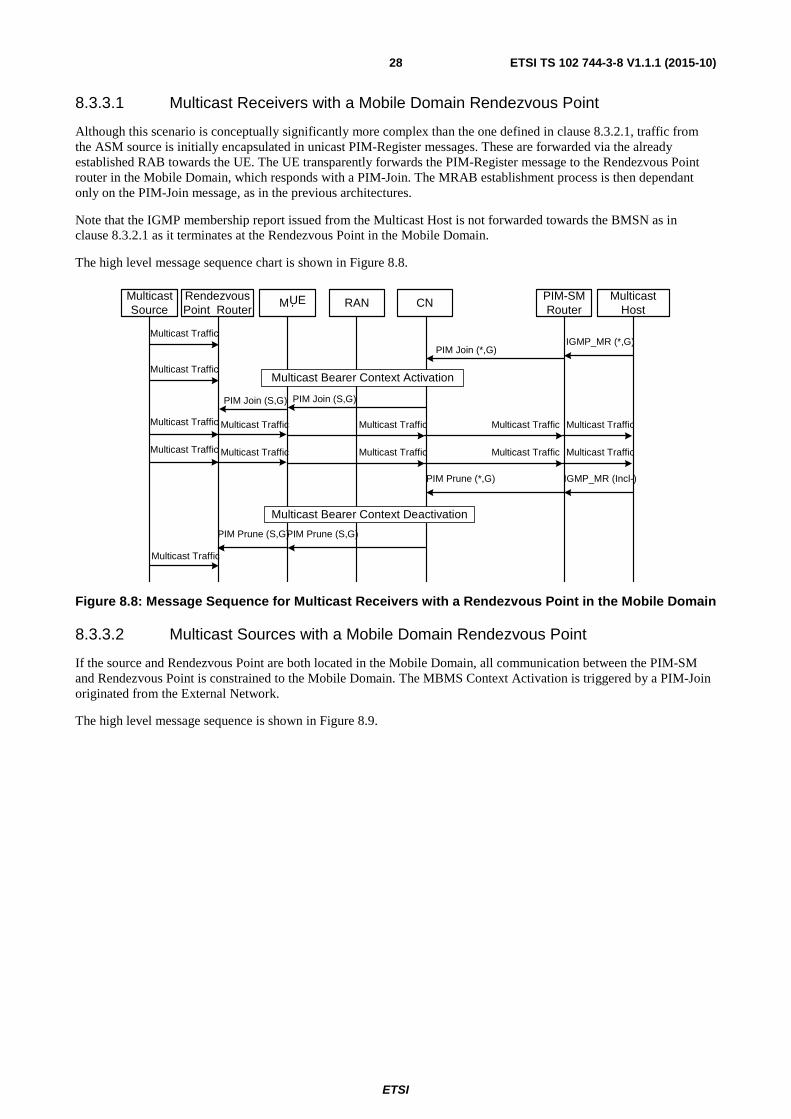
Although this scenario is conceptually significantly more complex than the one defined in clause 8.3.2.1, traffic from the ASM source is initially encapsulated in unicast PIM-Register messages. These are forwarded via the already established RAB towards the UE. The UE transparently forwards the PIM-Register message to the Rendezvous Point router in the Mobile Domain, which responds with a PIM-Join. The MRAB establishment process is then dependant only on the PIM-Join message, as in the previous architectures.
Note that the IGMP membership report issued from the Multicast Host is not forwarded towards the BMSN as in clause 8.3.2.1 as it terminates at the Rendezvous Point in the Mobile Domain.
The high level message sequence chart is shown in Figure 8.8.
Figure 8.8: Message Sequence for Multicast Receivers with a Rendezvous Point in the Mobile Domain
8.3.3.2 Multicast Sources with a Mobile Domain Rendezvous Point
If the source and Rendezvous Point are both located in the Mobile Domain, all communication between the PIM-SM and Rendezvous Point is constrained to the Mobile Domain. The MBMS Context Activation is triggered by a PIM-Join originated from the External Network.
The high level message sequence is shown in Figure 8.9.
MulticastSource
RendezvousPoint Router
MT RAN CNPIM-SMRouter
MulticastHost
Multicast TrafficMulticast Bearer Context Activation
Multicast TrafficMulticast Traffic Multicast Traffic
IGMP_MR (*,G)PIM Join (*,G)
IGMP_MR (Incl-)PIM Prune (*,G)
PIM Join (S,G)PIM Join (S,G)
Multicast Traffic Multicast Traffic
Multicast Traffic
Multicast Bearer Context Deactivation
PIM Prune (S,G)
Multicast Traffic
PIM Prune (S,G)
Multicast TrafficMulticast Traffic Multicast Traffic Multicast Traffic Multicast Traffic
UE

ETSI
ETSI TS 102 744-3-8 V1.1.1 (2015-10) 29
Figure 8.9: Message Sequence for Multicast Sources with a Rendezvous Point in the Mobile Domain
8.3.4 Maintenance of IP-Multicast Services using PIM-SM
PIM-SM is a 'soft-state' protocol. As such the state maintained in the BMSN will be continuously refreshed by the PIM update mechanism. If the group information is not refreshed within a certain time then the BMSN should determine that the group is no longer required and trigger a MBMS Context deactivation. It should be noted that the system is self-repairing, in that if connectivity is re-established, then the normal PIM-SM procedures will trigger the re-establishment of the MBMS contexts for provision of the requisite MBMS service.
8.4 BMSC triggered MBMS Services Activation of MBMS Services may be triggered by the initial activation of a Primary PDP Context towards the BM domain for a specific UE. This approach is used to support the network-initiated activation of MBMS Services when it is known that terminal equipment is unable to generate the requisite IGMP membership reports (for instance certain cryptographic devices), or for support of 'well-known' routing protocol group addresses that operate on a single-hop basis. Such MBMS Contexts remain in-place until the Primary PDP context is release, or until explicitly removed by the BMSC.
MulticastSource
MT RAN CNPIM-SMRouter
MulticastHost
Multicast Bearer Context Activation
Multicast Traffic
PIM Register
PIM Register STOP
Multicast Traffic Multicast Traffic
RendezvousPoint Router
IGMP_MR (*,G)
Multicast Traffic
IGMP_MR (Incl-)
PIM Prune (*,G)
PIM Join (S,G)PIM Join (S,G)
Multicast Traffic Multicast Traffic
Multicast TrafficMulticast TrafficMulticast Traffic Multicast Traffic Multicast Traffic
PIM Prune (S,G)
PIM Register
Multicast Bearer Context Deactivation
PIM Register
Multicast TrafficPIM RegisterMulticast Traffic
PIM Join (S,G)
PIM Prune (S,G)
Multicast Traffic
UE

ETSI
ETSI TS 102 744-3-8 V1.1.1 (2015-10) 30
History
Document history
V1.1.1 October 2015 Publication