ts 103 066 - v1.1.1 - railway telecommunications (rt); … ts 103 066 v1.1.1 (2011-10) railway...
TRANSCRIPT

ETSI TS 103 066 V1.1.1 (2011-10)
Railway Telecommunications (RT); Rel-4 Core Network requirements for GSM-R
Technical Specification
ETSI
ETSI TS 103 066 V1.1.1 (2011-10)2
Reference DTS/RT-00012
Keywords BICC, R-GSM
ETSI
650 Route des Lucioles F-06921 Sophia Antipolis Cedex - FRANCE
Tel.: +33 4 92 94 42 00 Fax: +33 4 93 65 47 16
Siret N° 348 623 562 00017 - NAF 742 C
Association à but non lucratif enregistrée à la Sous-Préfecture de Grasse (06) N° 7803/88
Important notice
Individual copies of the present document can be downloaded from: http://www.etsi.org
The present document may be made available in more than one electronic version or in print. In any case of existing or perceived difference in contents between such versions, the reference version is the Portable Document Format (PDF).
In case of dispute, the reference shall be the printing on ETSI printers of the PDF version kept on a specific network drive within ETSI Secretariat.
Users of the present document should be aware that the document may be subject to revision or change of status. Information on the current status of this and other ETSI documents is available at
http://portal.etsi.org/tb/status/status.asp
If you find errors in the present document, please send your comment to one of the following services: http://portal.etsi.org/chaircor/ETSI_support.asp
Copyright Notification
No part may be reproduced except as authorized by written permission. The copyright and the foregoing restriction extend to reproduction in all media.
© European Telecommunications Standards Institute 2011.
All rights reserved.
DECTTM, PLUGTESTSTM, UMTSTM and the ETSI logo are Trade Marks of ETSI registered for the benefit of its Members. 3GPPTM and LTE™ are Trade Marks of ETSI registered for the benefit of its Members and
of the 3GPP Organizational Partners. GSM® and the GSM logo are Trade Marks registered and owned by the GSM Association.

ETSI
ETSI TS 103 066 V1.1.1 (2011-10)3
Contents
Intellectual Property Rights ................................................................................................................................ 5
Foreword ............................................................................................................................................................. 5
Introduction ........................................................................................................................................................ 5
1 Scope ........................................................................................................................................................ 6
2 References ................................................................................................................................................ 6
2.1 Normative references ......................................................................................................................................... 6
2.2 Informative references ........................................................................................................................................ 8
3 Definitions and abbreviations ................................................................................................................... 8
3.1 Definitions .......................................................................................................................................................... 8
3.2 Abbreviations ..................................................................................................................................................... 8
4 Reference System Architecture for CS domain ........................................................................................ 9
4.1 Rel-99 Core Network architecture .................................................................................................................... 10
4.2 Rel-4 Core Network architecture ...................................................................................................................... 12
4.2.1 Main concept .............................................................................................................................................. 12
4.2.2 MSC Server ................................................................................................................................................ 13
4.2.3 GMSC Server.............................................................................................................................................. 13
4.2.4 Circuit Switched - Media Gateway Function (CS-MGW) .......................................................................... 13
4.2.5 Identities ..................................................................................................................................................... 14
4.2.5.1 Bearer Address and Binding Reference ................................................................................................ 14
4.2.5.2 CS-MGW-Id.......................................................................................................................................... 14
4.2.5.3 (G)MSC server Address ........................................................................................................................ 14
5 Interfaces requirement ............................................................................................................................ 14
5.1 Interfaces existing from Rel-99 onwards .......................................................................................................... 14
5.1.1 Interface between the MSC/MSC-S and Base Station System (A-interface) .............................................. 14
5.1.1.1 Interworking with GERAN (A interface) .............................................................................................. 15
5.1.2 Interface between the MSC/MSC-S and its associated VLR (B-interface) ................................................ 15
5.1.3 Interface between the HLR and the GMSC/GMSC-S (C-interface) ........................................................... 15
5.1.4 Interface between the HLR and the VLR (D-interface) .............................................................................. 15
5.1.5 Interface between MSCs/MSC-Ss (E-interface) ......................................................................................... 15
5.1.6 Interface between MSC/MSC-S and EIR (F-interface) .............................................................................. 16
5.1.7 Interface between VLRs (G-interface) ........................................................................................................ 16
5.1.8 External interface to fixed networks ........................................................................................................... 16
5.2 Interfaces introduced by Rel-4 distributed architecture .................................................................................... 16
5.2.1 Reference point (G)MSC server - CS-MGW (Mc Reference Point) .......................................................... 16
5.2.2 Reference Point MSC Server - GMSC Server (Nc Reference Point) ......................................................... 17
5.2.3 Reference Point CS-MGW - CS-MGW (Nb Reference Point) ................................................................... 17
6 Additional requirements for legacy procedures in BICN ....................................................................... 17
6.1 Call Establishment ............................................................................................................................................ 17
6.2 Call Clearing .................................................................................................................................................... 17
6.3 Handover .......................................................................................................................................................... 17
7 Additional requirements for legacy services in BICN............................................................................ 18
7.1 GSM Basic Services ......................................................................................................................................... 18
7.1.1 Circuit Bearer Services ............................................................................................................................... 18
7.1.2 Circuit Teleservices .................................................................................................................................... 18
7.1.3 Facsimile Service ........................................................................................................................................ 18
7.1.4 Voice Group Call Service ........................................................................................................................... 18
7.1.5 Voice Broadcast Service ............................................................................................................................. 18
7.2 Supplementary Services ................................................................................................................................... 18
7.2.1 eMLPP ........................................................................................................................................................ 18
7.2.2 Call Deflection Service description ............................................................................................................ 19
7.2.3 Line identification Supplementary Services ............................................................................................... 19
ETSI
ETSI TS 103 066 V1.1.1 (2011-10)4
7.2.4 Call Forwarding Supplementary Services................................................................................................... 19
7.2.5 Call Waiting and Call Hold Supplementary Services ................................................................................. 19
7.2.6 MultiParty Supplementary Services............................................................................................................ 19
7.2.7 Closed User Group Supplementary Service ................................................................................................ 19
7.2.8 Advice of Charge Supplementary Services ................................................................................................ 19
7.2.9 User-to-User Signalling .............................................................................................................................. 19
7.2.10 Call Barring supplementary services .......................................................................................................... 19
7.2.11 Unstructured Supplementary Service Data ................................................................................................. 19
7.2.12 Explicit Call Transfer Supplementary Service ............................................................................................ 20
7.2.13 Completion of Calls to Busy Subscriber Supplementary Service ............................................................... 20
7.2.14 Follow Me Service description ................................................................................................................... 20
7.3 Railway Specific Services and applications ..................................................................................................... 20
7.3.1 Confirmation of High Priority Call ............................................................................................................. 20
7.3.2 Functional Addressing ................................................................................................................................ 20
7.3.3 Location Dependent Addressing ................................................................................................................. 20
7.3.4 Presentation of Functional Numbers to Called and Calling Parties ............................................................ 20
7.3.5 Railway Emergency Call ............................................................................................................................ 20
7.3.6 Railway Specific Applications .................................................................................................................... 20
History .............................................................................................................................................................. 21

ETSI
ETSI TS 103 066 V1.1.1 (2011-10)5
Intellectual Property Rights IPRs essential or potentially essential to the present document may have been declared to ETSI. The information pertaining to these essential IPRs, if any, is publicly available for ETSI members and non-members, and can be found in ETSI SR 000 314: "Intellectual Property Rights (IPRs); Essential, or potentially Essential, IPRs notified to ETSI in respect of ETSI standards", which is available from the ETSI Secretariat. Latest updates are available on the ETSI Web server (http://ipr.etsi.org).
Pursuant to the ETSI IPR Policy, no investigation, including IPR searches, has been carried out by ETSI. No guarantee can be given as to the existence of other IPRs not referenced in ETSI SR 000 314 (or the updates on the ETSI Web server) which are, or may be, or may become, essential to the present document.
Foreword This Technical Specification (TS) has been produced by ETSI Technical Committee Railway Telecommunications (RT).
Introduction While the legacy architecture for a GSM-R network relies on the Rel-99 versions of the 3GPP/ETSI Technical Specifications, the technical evolutions in the area of Core Network architecture led some railways operators to deploy equipments based on the network architecture as described optionally in Rel-4 versions of the 3GPP/ETSI Technical Specifications. This Technical Specification addresses the description of Rel-4 Core Network Architecture and interface requirements for application on railway networks.

ETSI
ETSI TS 103 066 V1.1.1 (2011-10)6
1 Scope The present document describes the Rel-4 Core Network architecture as depicted in the Rel-4 version of the 3GPP/ETSI Technical Specifications for application on railway networks in order to provide the ability for railway operators to deploy a Rel-4 CN architecture, also known as Bearer Independent Core Network.
It then specifies the requirements on interfaces and procedures to operate such a Rel-4 Core Network architecture for railway usage.
The present document does not mandate Rel-4 CN architecture to become the reference architecture for railways, baseline for railway telecommunications remaining the Rel-99 version of the 3GPP/ETSI Technical Specifications.
Also the present document focuses on the changes from a Rel-99 to a Rel-4 CN architecture for the CS domain, as PS domain equipments and interfaces are not affected by the deployment of BICN.
The present document is focussing on the requirements concerning the architecture and the interfaces only. It does not take into consideration any other features or applications inserted into 3GPP/ETSI versions later than Rel-99.
2 References References are either specific (identified by date of publication and/or edition number or version number) or non-specific. For specific references, only the cited version applies. For non-specific references, the latest version of the reference document (including any amendments) applies.
Referenced documents which are not found to be publicly available in the expected location might be found at http://docbox.etsi.org/Reference.
NOTE: While any hyperlinks included in this clause were valid at the time of publication, ETSI cannot guarantee their long term validity.
2.1 Normative references The following referenced documents are necessary for the application of the present document.
[1] ETSI TS 123 002 (V3.6.0): "Digital cellular telecommunications system (Phase 2+); Universal Mobile Telecommunications System (UMTS); Network Architecture (3GPP TS 23.002 version 3.6.0 Release 1999)".
[2] ETSI TS 123 002 (V4.8.0): "Digital cellular telecommunications system (Phase 2+); Universal Mobile Telecommunications System (UMTS); Network architecture (3GPP TS 23.002 version 4.8.0 Release 4)".
[3] ETSI TS 123 205 (V5.11.0): "Universal Mobile Telecommunications System (UMTS); Bearer-independent circuit-switched core network; Stage 2 (3GPP TS 23.205 version 5.11.0 Release 5)".
[4] ETSI EN 301 515 (V2.3.0): "Global System for Mobile communication (GSM); Requirements for GSM operation on railways".
[5] ETSI TS 102 281 (V2.1.0): "Railways Telecommunications (RT); Global System for Mobile communications (GSM); Detailed requirements for GSM operation on Railways".
[6] UIC Project EIRENE: "European Integrated Railway Radio Enhanced Network, System Requirements Specification" P0011D010 Version: 15.1 dated 1st June 2010.
[7] ETSI EN 300 925 (V7.0.2): "Digital cellular telecommunications system (Phase 2+) (GSM); Voice Group Call Service (VGCS) - Stage 1 (GSM 02.68 version 7.0.2 Release 1999)".
[8] ETSI TS 100 933 (V8.2.0): "Digital cellular telecommunications system (Phase 2+) (GSM); Voice Group Call Service (VGCS); Stage 2 (GSM 03.68 version 8.2.0 Release 1999)".

ETSI
ETSI TS 103 066 V1.1.1 (2011-10)7
[9] ETSI TS 100 948 (V8.1.0): "Digital cellular telecommunications system (Phase 2+) (GSM); Group Call Control (GCC) protocol (GSM 04.68 version 8.1.0 Release 1999)".
[10] ETSI EN 300 926 (V8.0.1): "Digital cellular telecommunications system (Phase 2+) (GSM); Voice Broadcast Service (VBS) - Stage 1 (GSM 02.69 version 8.0.1 Release 1999)".
[11] ETSI TS 100 934 (V8.2.0): "Digital cellular telecommunications system (Phase 2+) (GSM); Voice Broadcast Service (VBS); Stage 2 (GSM 03.69 version 8.2.0 Release 1999)".
[12] ETSI TS 100 949 (V8.1.0): "Digital cellular telecommunications system (Phase 2+) (GSM); Broadcast Call Control (BCC) protocol (GSM 04.69 version 8.1.0 Release 1999)".
[13] ETSI TS 124 008 (V3.20.0): "Digital cellular telecommunications system (Phase 2+) (GSM); Universal Mobile Telecommunications System (UMTS); Mobile radio interface Layer 3 specification; Core network protocols; Stage 3 (3GPP TS 24.008 version 3.20.0 Release 1999).
[14] ETSI TS 100 590 (V8.5.0): "Digital cellular telecommunications system (Phase 2+) (GSM); Mobile-services Switching Centre - Base Station System (MSC - BSS) interface; Layer 3 specification (GSM 08.08 version 8.5.0 Release 1999)".
[15] ETSI TS 129 002 (V3.20.0): "Digital cellular telecommunications system (Phase 2+); Universal Mobile Telecommunications System (UMTS); Mobile Application Part (MAP) specification (3GPP TS 29.002 version 3.20.0 Release 1999)".
[16] ETSI TS 122 002 (V3.6.0): "Digital cellular telecommunications system (Phase 2+) (GSM); Universal Mobile Telecommunications System (UMTS); Circuit Bearer Services (BS) supported by a Public Land Mobile Network (PLMN) (3GPP TS 22.002 version 3.6.0 Release 1999)".
[17] ETSI TS 122 003 (V3.3.0): "Digital cellular telecommunications system (Phase 2+) (GSM); Universal Mobile Telecommunications System (UMTS); Circuit Teleservices supported by a Public Land Mobile Network (PLMN) (3GPP TS 22.003 version 3.3.0 Release 1999)".
[18] ETSI TS 122 067 (V3.0.1): "Digital cellular telecommunications system (Phase 2+) (GSM); Universal Mobile Telecommunications System (UMTS); enhanced Multi-Level Precedence and Pre-emption service (eMLPP) - Stage 1 (3G TS 22.067 version 3.0.1 Release 1999)".
[19] ETSI TS 100 932 (V7.2.0): "Digital cellular telecommunications system (Phase 2+) (GSM); enhanced Multi-Level Precedence and Pre-emption service (eMLPP); Stage 2 (3GPP TS 03.67 version 7.2.0 Release 1998)".
[20] ETSI TS 124 067 (V3.2.0): "Digital cellular telecommunications system (Phase 2+) (GSM); Universal Mobile Telecommunications System (UMTS); Enhanced Multi-Level Precedence and Pre-emption service (eMLPP); Stage 3 (3GPP TS 24.067 version 3.2.0 Release 1999)".
[21] ETSI TS 124 082 (V3.0.0): "Digital cellular telecommunications system (Phase 2+) (GSM); Universal Mobile Telecommunications System (UMTS); Call Forwarding (CF) supplementary services - Stage 3 (3G TS 24.082 version 3.0.0 Release 1999)".
[22] ETSI EN 301 702 (V7.1.2): "Digital cellular telecommunications system (Phase 2+) (GSM); User-to-User Signalling (UUS); Service description, Stage 1 (GSM 02.87 version 7.1.2 Release 98)".
[23] ETSI EN 301 710 (V7.0.2): "Digital cellular telecommunications system (Phase 2+) (GSM); User-to-User Signalling (UUS); Stage 2 (GSM 03.87 version 7.0.2 Release 1998)".
[24] ETSI EN 301 711 (V7.0.2): "Digital cellular telecommunications system (Phase 2+) (GSM); User-to-User Signalling (UUS); Stage 3 (GSM 04.87 version 7.0.2 Release 1998)".
[25] ETSI TS 122 090 (V3.1.0): " Digital cellular telecommunications system (Phase 2+) (GSM); Universal Mobile Telecommunications System (UMTS); Unstructured Supplementary Service Data (USSD) - Stage 1 (3G TS 22.090 version 3.1.0 Release 1999)".
[26] ETSI TS 123 090 (V3.2.0): "Digital cellular telecommunications system (Phase 2+) (GSM); Universal Mobile Telecommunications System (UMTS); Unstructured Supplementary Service Data (USSD) - Stage 2 (3GPP TS 23.090 version 3.2.0 Release 1999)".

ETSI
ETSI TS 103 066 V1.1.1 (2011-10)8
[27] ETSI TS 124 090 (V3.0.0): "Digital cellular telecommunications system (Phase 2+) (GSM); Universal Mobile Telecommunications System (UMTS); Unstructured Supplementary Service Data (USSD) - Stage 3 (3G TS 24.090 version 3.0.0 Release 1999)".
[28] ETSI TS 122 094 (V3.1.0): "Digital cellular telecommunications system (Phase 2+) (GSM); Universal Mobile Telecommunications System (UMTS); Follow Me Service description - Stage 1 (3G TS 22.094 version 3.1.0 Release 1999)".
[29] ETSI TS 123 094 (V3.2.0): "Digital cellular telecommunications system (Phase 2+) (GSM); Universal Mobile Telecommunications System (UMTS); Follow-Me (FM); Stage 2 (3GPP TS 23.094 version 3.2.0 Release 1999)".
[30] ETSI TS 122 004 (V3.3.0): "Digital cellular telecommunications system (Phase 2+); Universal Mobile Telecommunications System (UMTS); General on Supplementary Services (3GPP TS 22.004 version 3.3.0 Release 1999)".
[31] ETSI TS 129 232 (V4.17.0): "Universal Mobile Telecommunications System (UMTS); Media Gateway Controller (MGC) - Media Gateway (MGW) interface; Stage 3 (3GPP TS 29.232 version 4.17.0 Release 4)".
[32] UIC Project EIRENE: "European Integrated Railway Radio Enhanced Network, Functional Requirements Specification" P0011D009 Version: 7.1 dated 1st June 2010.
2.2 Informative references The following referenced documents are not necessary for the application of the present document but they assist the user with regard to a particular subject area.
[i.1] ETSI TR 101 748 (V8.0.0): "Digital cellular telecommunications system (Phase 2+) (GSM); Abbreviations and acronyms (GSM 01.04 version 8.0.0 Release 1999)".
[i.2] ETSI RT(10)0056: "R4 NSS "black box" replacement type".
NOTE: Available at: http://www.uic.org/IMG/pdf/rt_10_0056.pdf.
3 Definitions and abbreviations
3.1 Definitions For the purposes of the present document, the following terms and definitions apply:
core network: architectural term relating to the part of 3GPP System which is independent of the connection technology of the terminal (e.g. radio, wired)
3.2 Abbreviations For the purposes of the present document, the following abbreviations apply:
AAL2 ATM Adaptation Layer type 2 ATM Asynchronous Transfer Mode AuC Authentication Center BICC Bearer Independent Call Control BICN Bearer Independent Core Network BSC Base Station Controller BSS Base Station System BTS Base Transceiver Station CAP CAMEL Application Part CC Call Control CCBS Call Completion Busy Subscriber
ETSI
ETSI TS 103 066 V1.1.1 (2011-10)9
CFB Call Forwarding Busy CFU Call Forwarding Unconditional CH Call Hold CN Core Network CS Circuit Switched CS-MGW Circuit Switched - Media Gateway CW Call Waiting ECT Explicit Call Transfer EIR Equipment Identification Register GCR Group Call Register GMSC Gateway MSC GSM Global System for Mobile communication GSM-R Global System for Mobile communication for Railways applications GSMSC-S Gateway MSC Server HLR Home Location Register IMEI International Mobile Equipment Identification IMSI International Mobile Station Identifier IP Internet Protocol ISUP Integrated Service Digital Network User Part IWF Interworking Function MAP Mobile Application Part ME Mobile Equipment MEGACO MEdia GAteway COntrol MGW Media Gateway MPTY MultiParty MS Mobile Station MSC Mobile-services Switching Centre MSC-S MSC Server PLMN Plublic Land Mobile Network PS Packet Switched PSTN Public Switch Telephone Network QoS Quality of Service RTP Real-Time Transport Protocol SMS Short Message Service TC RT Technical Committee Railway telecommunications TDM Time Division Multiplex UDP User Datagram Protocol VBS Voice Broadcast Service VGCS Voice Group Call Service VLR Visitor Location Register
4 Reference System Architecture for CS domain This clause presents in a first part, for the sake of reminder, the legacy reference architecture of a Core Network built upon Rel-99 version of 3GPP/ETSI Technical Specifications. It then presents in a later part the reference architecture of Core Network built upon Rel-4 version of 3GPP/ETSI Technical Specifications.
The replacement of legacy CN architecture (Rel-99 CN architecture) by BICN (Rel-4 CN architecture) represents no difference with regards to functions and QoS referenced in [6] and [32] (backward compatibility: please refer to [i.2]). According to [2] a MSC/GMSC Server and a CS-MGW make up the full functionality of a MSC/GMSC.

ETSI
ETSI TS 103 066 V1.1.1 (2011-10)10
D
C CAP
CAP
Nb
A
A
Mc
Legend: Bold lines: Signalling and Data Transfer interfaces Dashed lines: Signalling interfaces
CS-MGW
Mc
CS-MGW Other Networks
Applications & Services
MSC Server GMSC Server
GERAN
Nc
HLR
Figure 1: CS core network logical architecture using BICN
The Bearer Independent Core Network concept, introduced in 3GPP Rel-4, relies mainly on the replacement of the MSC entity by the couple MSC-Server + Media Gateway. The entities common to the PS and CS domain, such as HLR, VLR, AuC or EIR, or the entities out of the Core Network are not affected by this difference. However, the requirements on the interfaces to MSC-S or CS-MGW are described in clause 5.
As the interface between the Group Call Register function and other functions is not specified in the GSM technical specifications, and different functional splits between MSC and GCR can be implemented (see [8]), the interface between the GCR and the MSC-S is left unchanged. GCR functions in BICN shall remain as specified for a Rel-99 CN architecture.
4.1 Rel-99 Core Network architecture In [1], the Mobile-services Switching Centre (MSC) constitutes the interface between the radio system and the fixed networks. The MSC performs all necessary functions in order to handle the circuit switched services to and from the mobile stations.

ETSI
ETSI TS 103 066 V1.1.1 (2011-10)11
BSS
BSC
CN
A
ME
MS
Um
MSC
GMSC
HLR
C
D
E
AuC H
EIR
F
PSTN
VLR
B
VLR G
BTS BTS
Abis
SIM
SIM-ME i/f
MSC
B
PSTN PSTN
Legend: Bold lines: interfaces supporting user traffic; Dashed lines: interfaces supporting signalling.
Figure 2: Basic Configuration of a PLMN using MSC entity
NOTE: The interface PSTN is used as synonym for interfaces to 'Other Networks' shown in figure 1.
The Mobile-services Switching Centre is an exchange which performs all the switching and signalling functions for mobile stations located in a geographical area designated as the MSC area. The main difference between a MSC and an exchange in a fixed network is that the MSC has to take into account the impact of the allocation of radio resources and the mobile nature of the subscribers and has to perform in addition procedures required for the location registration; and procedures required for handover.
If a network delivering a call to the PLMN cannot interrogate the HLR, the call is routed to an MSC. This MSC will interrogate the appropriate HLR and then route the call to the MSC where the mobile station is located. The MSC which performs the routing function to the actual location of the MS is called the Gateway MSC (GMSC).
If the call is a voice group/broadcast call, it is routed directly from the GMSC to the VBS/VGCS Anchor MSC, based on information (VBS/VGCS call reference) contained in the dialled number. See also [8] and [11].
ETSI
ETSI TS 103 066 V1.1.1 (2011-10)12
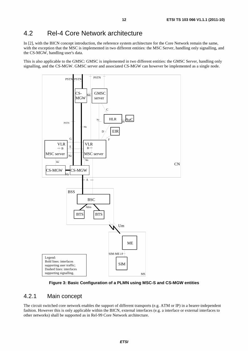
4.2 Rel-4 Core Network architecture In [2], with the BICN concept introduction, the reference system architecture for the Core Network remain the same, with the exception that the MSC is implemented in two different entities: the MSC Server, handling only signalling, and the CS-MGW, handling user's data.
This is also applicable to the GMSC: GMSC is implemented in two different entities: the GMSC Server, handling only signalling, and the CS-MGW. GMSC server and associated CS-MGW can however be implemented as a single node.
BSS
BSC
CN
ME
MS
Um
MSC server
GMSC server
HLR
C
D
Nc
H
EIR
F
PSTN
VLR B
VLR
G
BTS BTS
Abis
SIM
SIM-ME i/f
MSC server
B
PSTN
CS-MGW CS-MGW
CS-MGW
AuC
Nb
Mc Mc
Nb
PSTN PSTN
Nc
Mc
A
E
Legend: Bold lines: interfaces supporting user traffic; Dashed lines: interfaces supporting signalling.
Figure 3: Basic Configuration of a PLMN using MSC-S and CS-MGW entities
4.2.1 Main concept
The circuit switched core network enables the support of different transports (e.g. ATM or IP) in a bearer-independent fashion. However this is only applicable within the BICN, external interfaces (e.g. a interface or external interfaces to other networks) shall be supported as in Rel-99 Core Network architecture.

ETSI
ETSI TS 103 066 V1.1.1 (2011-10)13
For the ATM and IP transport, there is a strict separation between the call control level and the bearer control level. In the case of ATM or IP transport, the passage of compressed speech at variable bit rates is possible through the CS core network.
The CS core network shall employ the MSC server, GMSC server and media gateways. The GMSC server and MSC server shall provide the call control and mobility management functions, and the media gateway shall provide the bearer control and transmission resource functions. The media gateway shall contain the stream manipulating functions.
The GMSC server and MSC servers are connected to the media gateway via the Mc reference point. The MSC servers and GMSC servers are connected with the Nc reference point. There may be a number of call control transit nodes between the MSC server and GMSC server in the Nc reference point. The MGWs are connected with the Nb reference point. Also, it has to be noted that according to [3] a Rel-4 (or later) node is backward compatible with a Rel-99 (or earlier) node.
The users connected to the CS core network shall not be aware whether a MSC-S + CS-MGW combination is used, or a monolithic MSC is used.
4.2.2 MSC Server
The MSC-S mainly comprises the call control and mobility control parts of a MSC.
It is responsible for the control of mobile originated and mobile terminated CC CS Domain calls. It terminates the user-network signalling (see [13]) and translates it into the signalling over the Nc interface. It also terminates the signalling over the Mc interface with the media gateway.
The MSC-S controls the parts of the call state model that pertain to connection control for media channels in an MGW. It also contains the 'Call Control Function' in the BICC model.
The MSC-S is also integrated with a VLR to hold the mobile subscriber's service data.
4.2.3 GMSC Server
The GMSC-S mainly comprises the call control and mobility control parts of a GMSC.
The GMSC-S terminates the signalling over the Nc interface and the call control interfaces to the external networks. It also terminates the signalling over the Mc interface towards the media gateway.
The GMSC server controls the parts of the call state model that pertain to connection control for media channels in an MGW. It also contains the 'Call Control Function' in the BICC model
4.2.4 Circuit Switched - Media Gateway Function (CS-MGW)
The CS-MGW terminates the signalling over the Mc interface from the (G)MSC-S. It also terminates the bearer part of the signalling over the A interface and the Nb interface.
A CS-MGW may terminate bearer channels from a switched circuit network and media streams from a packet network (e.g., RTP streams in an IP network). Over A, the CS-MGW may support media conversion, bearer control and payload processing (e.g. codec, echo canceller, conference bridge) for support of different A options for CS services (AAL2/ATM based as well as RTP/UDP/IP based).
The CS-MGW:
- Interacts with MSC-S and GMSC-S for resource control;
- Owns and handles resources such as echo cancellers, etc.;
- May need to have codecs.
The CS-MGW will be provisioned with the necessary resources for supporting GSM transport media. Further tailoring (i.e. packages) of the H.248 may be required to support additional codecs and framing protocols, etc.
The CS-MGW bearer control and payload processing capabilities will also need to support mobile specific functions such as handover and anchoring. H.248 standard mechanisms can be applied to enable this.
ETSI
ETSI TS 103 066 V1.1.1 (2011-10)14
4.2.5 Identities
4.2.5.1 Bearer Address and Binding Reference
The Bearer Address is exchanged on the Nc and Mc interfaces to identify the termination point of the bearer control signalling within the peer CS-MGW.
A Binding Reference is an identity, unique within the scope of one bearer control function, which identifies a bearer network connection. This information is exchanged on the Nc and Mc interfaces. The bearer control function is identified by the Bearer Address.
4.2.5.2 CS-MGW-Id
The CS-MGW Identity (CS-MGW-Id) is information sent on the Nc interface to aid CS-MGW selection by the succeeding/preceding node.
The CS-MGW-Id is bearer independent and it can be translated into a signalling address towards the appropriate CS-MGW.
4.2.5.3 (G)MSC server Address
The (G)MSC-S Address defines the signalling address associated with the (G)MSC-S that is used to interact with the CS-MGW over the Mc interface. This is a unique address in the network service supplier domain.
5 Interfaces requirement In this clause the existing interfaces described in Rel-99 version of the 3GPP/ETSI Technical Specifications which are affected by the introduction of MSC-S/CS-MGW in replacement of MSC are detailed and requirements on those interfaces are given.
Additionally, new interfaces introduced by the BICN concept (Mc-, Nc-, Nb- reference point) are also detailed, and requirements on those interfaces are given.
In the basic configuration presented in figures 2 and 3, all the functions are considered implemented in different equipments. Therefore, all the interfaces within PLMN are external. From this configuration, all the possible PLMN organisations can be deduced. In the case when some functions are contained in the same equipment, the relevant interfaces become internal to that equipment.
5.1 Interfaces existing from Rel-99 onwards
5.1.1 Interface between the MSC/MSC-S and Base Station System (A-interface)
The BSS-MSC interface is used to carry information concerning:
- BSS management;
- call handling;
- mobility management.
When used in BICN, the A-interface signalling terminates in the MSC-S and the user plane terminates in the CS-MGW, but the requirements for the physical layer, signalling transport mechanism, interface protocols (see [14]), and rate adaption are left unchanged.

ETSI
ETSI TS 103 066 V1.1.1 (2011-10)15
5.1.1.1 Interworking with GERAN (A interface)
In the A-interface the only supported user plane up to Rel-8 is a TDM circuit. The MSC-S uses the Mc interface to remotely control the TDM circuits in the CS-MGW.
For each TDM circuit a physical termination is provisioned in the CS-MGW. The TDM circuit is identified by the termination Id in the Mc interface. Since TDM circuits are also grouped together, the physical termination Ids are structured in accordance with the grouping of TDM circuits. The MSC-S also knows the termination Ids and the grouping of termination Ids. The physical termination exists as long as the TDM circuit(s) exists in the CS-MGW. For n TDM circuits, the MSC-S has a mapping table between circuits CIC1-CICn and the terminations T1-Tn.
For call-independent transactions, the general (G)MSC-S - CS-MGW procedures, as described in clause10 of [3], apply to the physical terminations in the same way as to any other terminations.
For call related transactions the handling as described in the clause 6, 7 and 8 of [3] apply to physical terminations in the same way as any other terminations.
For intra-MSC handover, the target A-interface is handled as described in clause clause 8.4.1 of [3]. If the target A-interface user plane terminates in a different CS-MGW from the CS-MGW that terminates the serving A-interface user plane, a bearer has to be established between the two CS-MGWs. Because the same MSC-S controls both MGWs, no external call control signalling is involved.
5.1.2 Interface between the MSC/MSC-S and its associated VLR (B-interface)
The VLR is the location and management data base for the mobile subscribers roaming in the area controlled by the associated MSC(s). Whenever the MSC needs data related to a given mobile station currently located in its area, it interrogates the VLR. When a mobile station initiates a location updating procedure with an MSC, the MSC informs its VLR which stores the relevant information. This procedure occurs whenever an MS roams to another location area. Also, when a subscriber activates a specific supplementary service or modifies some data attached to a service, the MSC informs (via the VLR) the HLR which stores these modifications and updates the VLR if required.
This interface is internal to the MSC and MSC-S/VLR; signalling on it is not fully standardised. When used in BICN, the MSC-S is required to perform all the tasks previously done by the MSC. It is to be noted that according to [3], the MSC-S is integrated with a VLR to hold the mobile subscriber's service data.
5.1.3 Interface between the HLR and the GMSC/GMSC-S (C-interface)
The GMSC must interrogate the HLR of the required subscriber to obtain routing information for a call or a short message directed to that subscriber.
When used in BICN, this interface is set between the GMSC-S and the HLR, but the requirements for signalling via the Mobile Application Part (MAP) protocol (see [15]) are left unchanged.
5.1.4 Interface between the HLR and the VLR (D-interface)
This interface is used to exchange the data related to the location of the mobile station and to the management of the subscriber. The main service provided to the mobile subscriber is the capability to set up or to receive calls within the whole service area.
When used in BICN, this interface is set between the VLR and the HLR, but the requirements for signalling via the Mobile Application Part (MAP) protocol (see [15]) are left unchanged.
5.1.5 Interface between MSCs/MSC-Ss (E-interface)
When a mobile station moves from one MSC area to another during a call, a handover procedure has to be performed in order to continue the communication. For that purpose the MSCs have to exchange data to initiate and then to realise the operation. After the handover operation has been completed, the MSCs will exchange information to transfer A interface signalling.

ETSI
ETSI TS 103 066 V1.1.1 (2011-10)16
When used in BICN, this interface is set between two MSC-S, but the requirements for handover procedure, and signalling via the Mobile Application Part (MAP) protocol (see [15]) still apply. Additional requirements are described in clause 6.3.
5.1.6 Interface between MSC/MSC-S and EIR (F-interface)
This interface is used between MSC and EIR to exchange data, in order that the EIR can verify the status of the IMEI retrieved from the Mobile Station.
When used in BICN, this interface is set between the MSC-S and the EIR, but the requirements for signalling via the Mobile Application Part (MAP) protocol (see [15]) are left unchanged.
5.1.7 Interface between VLRs (G-interface)
When a mobile subscriber moves from one VLR area to another Location Registration procedure will happen. This procedure may include the retrieval of the IMSI and authentication parameters from the old VLR.
When used in BICN, this interface is set between two MSC-S, but the requirements for signalling via the Mobile Application Part (MAP) protocol (see [15]) are left unchanged.
NOTE: A configuration interfacing a MSC with a MSC-S within the same PLMN is not applicable in railway environment
5.1.8 External interface to fixed networks
The Interworking Function (IWF) is a functional entity associated with the MSC. The IWF provides the functionality necessary to allow interworking between a PLMN and the fixed networks (ISDN, PSTN and PDNs). The functions of the IWF depend on the services and the type of fixed network. The IWF is required to convert the protocols used in the PLMN to those used in the appropriate fixed network. The IWF may have no functionality where the service implementation in the PLMN is directly compatible with that at the fixed network.
When used in BICN, this functional entity is associated with the MSC-S, and the requirements to support interworking between PLMN and the fixed networks for circuit switched services in the PLMN are left unchanged.
5.2 Interfaces introduced by Rel-4 distributed architecture
5.2.1 Reference point (G)MSC server - CS-MGW (Mc Reference Point)
The Mc reference point describes the interfaces between the MSC-S and CS-MGW, and between the GMSC-S and CS-MGW. It has the following properties:
- full compliance with the H.248 standard, baseline work of which is currently carried out in ITU-T Study Group 16, in conjunction with IETF MEGACO WG.
- flexible connection handling which allows support of different call models and different media processing purposes not restricted to H.323 usage.
- open architecture where extensions/Packages definition work on the interface may be carried out.
- dynamic sharing of MGW physical node resources. A physical MGW can be partitioned into logically separate virtual MGWs/domains consisting of a set of statically allocated terminations.
- dynamic sharing of transmission resources between the domains as the MGW controls bearers and manage resources according to the H.248 protocols.
H.248/MEGACO has been jointly developed within the ITU-T and the IETF, and supports a separation of call control entities from bearer control entities, and a separation of bearer control entities from transport entities. H.248 is used on the Mc interface between the (G)MSC servers and the media gateway (see [31]).
All the general (G)MSC-S - CS-MGW procedures are further detailed in [3] clause 10.
ETSI
ETSI TS 103 066 V1.1.1 (2011-10)17
5.2.2 Reference Point MSC Server - GMSC Server (Nc Reference Point)
The Nc reference point describes the Network-Network based call control. Any suitable call control protocol may be used over the Nc interface allowing the physical separation of the call control entities from the bearer control entities. Examples of this are ISUP or an evolvement of ISUP for bearer independent call control (BICC). In the Rel-4 architecture different options for signalling transport on Nc shall be possible including IP.
The specification of the interworking between the Nc reference point, call control protocols and ISUP is outside the scope of the present document.
All the messages exchanged between (G)MSC-S are further detailed in [3], clause 16.
5.2.3 Reference Point CS-MGW - CS-MGW (Nb Reference Point)
The Nb reference point describes the interface between CS-MGWs. The bearer control signalling and transport are carried over the Nb interface. The transport may be RTP/UDP/IP or AAL2 for transport of user data. In the Rel-4 architecture different options for user data transport and bearer control shall be possible on Nb, for example:
AAL2/Q.AAL2, STM/none, RTP/H.245.
The specification of the interworking on the Nb reference point is outside the scope of the present document.
6 Additional requirements for legacy procedures in BICN
Legacy procedures handled by the MSC include call establishment / call clearing, and handover/relocation. This clause identifies the additional requirements needed for those procedures for the bearer independent CS Core Network.
6.1 Call Establishment All the additional requirements for call establishment are described in [3]:
- Basic Mobile Originating Call (see clause 6.1).
- Basic Mobile Terminating Call (see clause 6.2).
6.2 Call Clearing All the additional requirements for call clearing are described in [3]:
- Network Initiated (see clause 7.1).
- User Initiated (see clause 7.2).
- (G)MSC-S Initiated (see clause 7.3).
- CS-MGW Initiated (see clause 7.4).
6.3 Handover All the additional requirements for handover are described in [3]:
- Intra-MSC GSM to GSM Handover (see clause 8.4.1).
- Basic Inter-MSC GSM to GSM Handover (see clause 8.4.2).
- Subsequent Inter-MSC GSM to GSM Handover back to the Anchor MSC (see clause 8.4.3).
- Subsequent GSM to GSM Handover to a third MSC (see clause 8.4.5).

ETSI
ETSI TS 103 066 V1.1.1 (2011-10)18
7 Additional requirements for legacy services in BICN Legacy services interact with the MSC in a Rel-99 CN architecture .Whenever a change for BICN architecture affects legacy services used for railways, this clause identifies the additional requirements needed for those procedures for the bearer independent CS Core Network.
7.1 GSM Basic Services The list of the following GSM Basic services is taken from [16] and [17], VGCS/VBS taken from [7], [8], [9], [10], [11] and [12].
7.1.1 Circuit Bearer Services
Circuit Bearer Services supported by a Public Land Mobile Network are not impacted by BICN.
7.1.2 Circuit Teleservices
Circuit Teleservices (including telephony and SMS) supported by a Public Land Mobile Network are not impacted by BICN.
7.1.3 Facsimile Service
The technical Realization of Facsimile Group 3 Service - transparent and non transparent needs additional requirements in BICN, as described in [3]:
- Alternate Speech/Fax (see clause 13.17).
- GSM Fax (see clause 13.18).
7.1.4 Voice Group Call Service
The voice group call service is not impacted by BICN.
7.1.5 Voice Broadcast Service
The voice broadcast service is not impacted by BICN.
7.2 Supplementary Services The list of the following supplementary services is taken from
- [18], [19] and [20] for eMLPP.
- [21] for Call Forwarding.
- [22], [23] and [24] for User to User signalling.
- [25], [26] and [27] for Unstructured Supplementary Service Data.
- [28] and [29] for Follow Me.
- [30] for all other supplementary services.
7.2.1 eMLPP
The enhanced Multi-Level Precedence and Pre-emption service is not impacted by BICN.

ETSI
ETSI TS 103 066 V1.1.1 (2011-10)19
7.2.2 Call Deflection Service description
The call deflection service needs additional requirements in BICN, as described in [3]:
- Call Deflection Service (see clause 13.2).
7.2.3 Line identification Supplementary Services
The line identification supplementary services are not impacted by BICN.
7.2.4 Call Forwarding Supplementary Services
The call forwarding supplementary services need additional requirements in BICN, as described in [3]:
- Call Forwarding Unconditional (CFU) (see clause 13.4.1).
- Call Forwarding on mobile subscriber Busy (CFB) (see clause 13.4.2).
- Call Forwarding on No Reply (CFNRy) (see clause 13.4.3).
- Call Forwarding on mobile subscriber Not Reachable (CFNRc) (see clause 13.4.4).
7.2.5 Call Waiting and Call Hold Supplementary Services
The call waiting and call hold supplementary services need additional requirements in BICN, as described in [3]:
- Call Waiting (CW) (see clause 13.5).
- Call Hold (CH) (see clause 13.6).
7.2.6 MultiParty Supplementary Services
The MultiParty supplementary service needs additional requirements in BICN, as described in [3]:
- MultiParty (MPTY) (see clause 13.7).
7.2.7 Closed User Group Supplementary Service
The closed user group supplementary service is not impacted by BICN.
7.2.8 Advice of Charge Supplementary Services
The Advice of Charge supplementary service is not impacted by BICN.
7.2.9 User-to-User Signalling
The User-to-User Signalling service is not impacted by BICN.
7.2.10 Call Barring supplementary services
The Call Barring supplementary services are not impacted by BICN.
7.2.11 Unstructured Supplementary Service Data
The Unstructured Supplementary Service Data is not impacted by BICN.
ETSI
ETSI TS 103 066 V1.1.1 (2011-10)20
7.2.12 Explicit Call Transfer Supplementary Service
The Explicit Call Transfer supplementary service needs additional requirements in BICN, as described in [3]:
- Explicit Call Transfer (ECT) (see clause 13.12).
7.2.13 Completion of Calls to Busy Subscriber Supplementary Service
The Completion of Calls to Busy Subscriber supplementary service needs additional requirements in BICN, as described in [3]:
- Completion of Calls to Busy Subscriber (CCBS) (see clause 13.13).
7.2.14 Follow Me Service description
The Completion of Follow Me service is not impacted by BICN.
7.3 Railway Specific Services and applications The list of the following railway specific services and applications is taken from [6].
7.3.1 Confirmation of High Priority Call
The confirmation of high priority call service is not impacted by BICN.
7.3.2 Functional Addressing
The functional addressing service is not impacted by BICN.
7.3.3 Location Dependent Addressing
The location dependent addressing is not impacted by BICN.
7.3.4 Presentation of Functional Numbers to Called and Calling Parties
The presentation of functional numbers to called and calling parties is not impacted by BICN.
7.3.5 Railway Emergency Call
The railway emergency call is not impacted by BICN.
7.3.6 Railway Specific Applications
The railway specific applications (see clause 1.4.1.1 of [6]) are not impacted by BICN.

ETSI
ETSI TS 103 066 V1.1.1 (2011-10)21
History
Document history
V1.1.1 October 2011 Publication