ts -ms… master lead/lag panels for boiler management, and
TRANSCRIPT

SCC Inc. Technical Instructions
Document No. TS-2000 June 16, 2020
SCC Inc.
TS Series
TS-MS… Master Lead/Lag Panels for Boiler
Management, and Building Management
System Interface
Description
A TS-MS… series Master Lead/Lag Panel sequences and
controls up to eight boilers equipped with TS...
communication kits and/or TS… combustion enclosures.
TS-MS… Master Panel options include communication to
TS-D… Deaerator/Surge panel control systems.
A Master Panel controls hot water or steam boilers with
Siemens LMV linkageless control systems, with or without an
RWF… controller for load or water level control. Each panel
includes a 7”, 10”, or 12” touchscreen and programmable
logic controller (PLC).
Flexible communication interface options to the building
management system (BMS) provide streamlined data
collection, monitoring, and control. Additional options
include control of circulating pumps, analog input
monitoring for hot water boilers, or temperature monitoring
for steam boilers.

Technical Instructions TS Series
Document No. TS-2000
Page 2 SCC Inc.
Standard
Features
7”, 10”, or 12” touchscreen
Programmable Logic Controller (PLC)
Manages up to eight (8) boilers with Siemens LMV… controllers
Lead/lag with automatic boiler rotation
Lead and lag boiler order selection
Parallel, sequential, or parallel PV, modulation
Remote enable and setpoint adjustment via BMS
Time / temperature based hot standby
Low temperature / low fire hold
System steam flow or MBTU totalization based upon firing rate
Controlling systems with combination of TS… touchscreen kits
or TS… serial kits at each boiler with Siemens LMV linkageless
systems
Control system with or without the RWF for water level control
or RWF55 for load control
Water level monitoring with RWF55 loop controllers
Forced lead boiler selection
Forced lead boiler to stop boiler rotation
Forced boiler not to be the lead boiler
Forced number of boilers in lead lag rotation
Forced individual boilers to lower firing rate, when boiler
pressure exceeds setpoint plus an offset LFH
Hand-Off-Auto selection
Override setpoint mode via a digital input
Boiler firing based on predetermined daily schedule
Individual boiler alarms and status
Graphics for individual boiler overview screens are configured
based on Master Panel selections
Individual boiler or master touchscreen graphics capture to USB
drive
Monitored digital outputs can be configured to take action
based upon the value in any of the Modbus registers
Standard or Metric units display
English or Spanish language options
Twelve (12) selectable data logging variables stored in CSV
format on USB drive
Real time trending and data logging to a USB thumb drive
Six (6) selectable variables for trending up to 7 days
Alarm history stored for most recent 250 alarms
Screen saver with process variable (PV), setpoint, and demand
Ethernet and serial communications to local boilers

TS Series Technical Instructions
Document No. TS-2000
SCC Inc. Page 3
Standard Modbus TCP/IP or RTU to BMS communications
Additional BMS communication options available
Email and text messaging includes alarms and screen shots for
up to six (6) recipients
Screen shot viewer via USB
Remote monitoring via smartphone or tablet
Interface to SCC Deaerator/Surge tank control panel
Short cut navigation from the overview screen
Multi-level, password protected screens
Four (4) analog inputs with field configurable label, span, and
type (0-10V, 2-10V, 0-20mA or 4-20mA). Each with low and
high alarm setpoints, with auto or manual reset. Totalization
available per minute or per hour. Optional for hot water boilers
Two (2) analog outputs with field configurable span and type (0-
10V, 2-10V, 0-20mA or 4-20mA). Each with low and high alarm
setpoints, with auto or manual reset. Totalization available per
minute or per hour. Optional with the analog input module
selection for hot water boilers
Four (4) 1000 RTD temperature inputs with field configurable
label. Each with low and high alarm setpoints, with auto or
manual reset. Optional for steam boilers
Four (4) digital outputs with field configurable logic, including
on and off delays. Manual or automatic reset
Outside air reset for hot water boilers
Individual circulating pump control outputs for hot water
boilers
Hot water system 2 pumps VFD control, VFD or starters start
stop control
Application
TS-MS Lead/Lag Panels are engineered for hot water boilers, steam
boilers, or other applications utilizing LMV3 or LMV5 linkageless
control systems, with or without RWF, for load or water level
controls.
Components
All TS-MS… Master Panels include the following components:
7”, 10”, or 12” touchscreen
Programmable Logic Controller (PLC)
Power supply and branch circuit protection
Digital, analog, and RTD input modules
Analog and digital inputs and outputs
Interconnect terminals for field wiring

Technical Instructions TS Series
Document No. TS-2000
Page 4 SCC Inc.
Product Part Numbers
Master Lead/Lag panel part number identification.
TS - MS
8
1
0
S - S
X
X
Touchscreen
Master Lead/Lag
Number Of Boilers
4 = Up to four boilers and SCC DA/Surge Panel
5 = Up to five boilers
7 = Up to seven boilers and SCC DA/Surge Panel
8 = Up to eight boilers
9 = Up to eight boilers and SCC DA/Surge Panel
Enclosure
1 = NEMA 1
2 = NEMA 12, includes cover over the touchscreen
4 = NEMA 4X
A = NEMA 1 with cooling fan
B = NEMA 12 with cooling fan, includes cover over touchscreen and fan
C = NEMA 4X with cooling fan, includes cover over fan
Touchscreen Size
7 = 7.0" touchscreen
0 = 10" touchscreen
2 = 12" touchscreen
BMS Communication
S = Modbus TCP/IP and Modbus RTU 485
B = BACnet/IP or Ethernet/IP
L = LonWorks
M = BACnet MS/TP, or Johnson Metasys N2
N = Profinet
P = Profibus
Application
S = Steam boilers with TS touchscreen kits at each boiler
H = Hot water boilers with TS touchscreen kits at each boiler
R = Steam boilers with serial kits at each boiler
W = Hot water with serial kits at each boiler
U = Universal steam boilers with TS touchscreen kits and serial kits at each boiler
Z = Universal hot water boilers with TS touchscreen kits and serial kits at each boiler
Temperature Measurement for Steam Boilers or Analog Measurement for Hot Water Boilers
T = 4 RTD 1000 Ohm inputs (only for selection S, R, or U application above)
A = 4 analog inputs module (only for selection H, W, or Z application above)
X = None
Circulating Pump Controls (Hot water applications H, W, or Z only)
P = Circulating pump controls (based on number of hot water boilers selected above)
X = None

TS Series Technical Instructions
Document No. TS-2000
SCC Inc. Page 5
Specifications
7”
Touchscreen
10”
Touchscreen
12”
Touchscreen
Electrical
Characteristics Operating Voltage 110-120 VAC 110-120 VAC 110-120 VAC
Operating Frequency 50-60 HZ 50-60 HZ 50-60 HZ
Power Consumption Full
Load 360VA 360VA 360VA
TS Touchscreen Power 24 VDC 24 VDC 24 VDC
TS Power Consumption ≤ 6.8 W ≤ 17 W ≤ 19 W
Dry Contacts 2 Amps 2 Amps 2 Amps
Operating
Environment Operating Temperature
32 to 122 °F
[0 to 50 °C]
32 to 131 °F
[0 to 55 °C]
32 to 131 °F
[0 to 55 °C]
Humidity
Max. 80%
with no
condensation
Max. 85%
with no
condensation
Max. 85%
with no
condensation
NEMA Rating (Standard)
1
1
1
NEMA Rating (Optional)
4-4X Indoor
NEMA 12
4-4X Indoor
NEMA 12
4-4X Indoor
NEMA 12
Field Cables
(By others)
Between Master and Boiler
Touchscreens CAT5E-CAT6-CAT6e-CAT7
Between Master and Serial
Kits (no touchscreens) Belden 3106A recommended
BMS Cable
Length
Modbus RTU RS232
Connection
Up to 15 feet
Modbus RTU
RS485
Connection
Up to 1500 feet
All Other Protocols Adhere to BMS protocol wiring specifications

Technical Instructions TS Series
Document No. TS-2000
Page 6 SCC Inc.
Specifications (continued)
Note: For all RS485 connections, use Belden Cable 3106A (multi-conductor cable with twisted
pair, EIA Industrial RS485 PLTC/COM) or equivalent.
Table 1: Belden Cable 3106A Wire Color Designation
Electrical Diagram Belden Cable 3106A
Red (RS485+) Orange (RS485+)
Black (RS485-) White (RS485-)
White (SG) Blue (SG)

TS Series Technical Instructions
Document No. TS-2000
SCC Inc. Page 7
Connections
Power Connections
Digital Input Remote Control Terminals
Digital Inputs

Technical Instructions TS Series
Document No. TS-2000
Page 8 SCC Inc.
Connections (continued)
Outputs Monitored Value Terminals
PLC Output Alarm Terminals

TS Series Technical Instructions
Document No. TS-2000
SCC Inc. Page 9
Connections (continued)
Hot Water Boilers Only (Application H, W or Z): Digital Input Pump Proven Terminals
Note: Number of boilers in the part number corresponds to the number of wired digital inputs for
pump proven terminals

Technical Instructions TS Series
Document No. TS-2000
Page 10 SCC Inc.
Connections (continued) Hot Water Boilers Only (Application H, W, or Z): Digital Output Pump Control Terminals
Note: Number of boilers in the part number corresponds to the number of wired digital outputs for
pump control terminals

TS Series Technical Instructions
Document No. TS-2000
SCC Inc. Page 11
Connections (continued) Hot Water Boilers Only (Application H, W, or Z): Digital Output Pump Control Terminals
Note: For four boilers or less to be able to control one circulating pump, and one isolation valve, per
boiler. Master panel has to be ordered for up to 8 boilers to achieve this control, regardless how many
boilers are actually connected.

Technical Instructions TS Series
Document No. TS-2000
Page 12 SCC Inc.
Connections (continued)
Analog Input and Output Terminals (one module)
- Standard for Steam Boilers (Application S, R, or U)
- Optional for Hot Water Boilers (Application H, W or Z)

TS Series Technical Instructions
Document No. TS-2000
SCC Inc. Page 13
Connections (continued)
Analog Input and Output Terminals (one module) continued

Technical Instructions TS Series
Document No. TS-2000
Page 14 SCC Inc.
Connections (continued)
RTD Pt or LG-Ni 1000 Ohm Input Terminals
- Standard for Hot Water Boilers (Application H, W or Z)
- Optional for Steam Boilers (Application S, R, or U)

TS Series Technical Instructions
Document No. TS-2000
SCC Inc. Page 15
Connections (continued) RTD Pt or LG-Ni 1000 Ohm input Terminals
- Optional for Steam Boilers (Application S, R, or U)

Technical Instructions TS Series
Document No. TS-2000
Page 16 SCC Inc.
Connections (continued)
Ethernet connection with TS kits at each boiler and Deaerator/Surge control system (if applicable)
- Ethernet connections for up to 5 TS kits, or up to 4 TS kits with SCC Deaerator/Surge control
system. Ethernet cables not included.
NOTE 1: Wire all CAT5E cables separately from AC power wires.
Note 2: If a second DA or second Surge tank SCC control panel connection required, the maximum
boiler connections will be reduced by one.

TS Series Technical Instructions
Document No. TS-2000
SCC Inc. Page 17
Connections (continued)
Ethernet connections for up to 8 TS kits, or up to 7 TS kits with Deaerator/Surge control system.
Ethernet cables not included.
NOTE 1: Wire all CAT5E cables separately from AC power wires.
Note 2: If a second DA or second Surge tank SCC control panel connection required, the maximum
boiler connections will be reduced by one.

Technical Instructions TS Series
Document No. TS-2000
Page 18 SCC Inc.
Connections (continued)
Ethernet connection for up to 8 TS kits and Deaerator/Surge control system. Ethernet cables not
included.
NOTE 1: Wire all CAT5E cables separately from AC power wires.
Note 2: If a second DA or second Surge tank SCC control panel connection required, the maximum
boiler connections will be reduced by one.
TS Series Technical Instructions
Document No. TS-2000
SCC Inc. Page 19
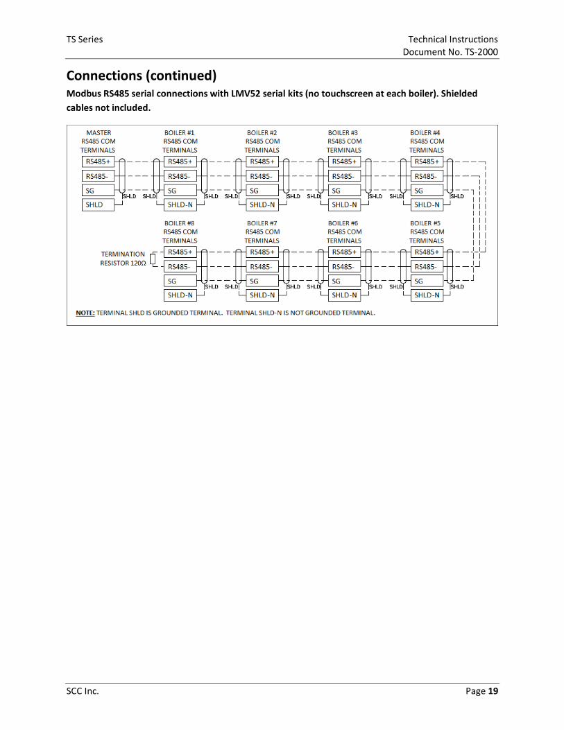
Connections (continued)
Modbus RS485 serial connections with LMV52 serial kits (no touchscreen at each boiler). Shielded
cables not included.
Technical Instructions TS Series
Document No. TS-2000
Page 20 SCC Inc.
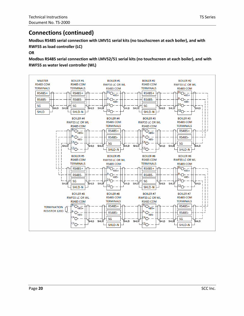
Connections (continued) Modbus RS485 serial connection with LMV51 serial kits (no touchscreen at each boiler), and with
RWF55 as load controller (LC)
OR
Modbus RS485 serial connection with LMV52/51 serial kits (no touchscreen at each boiler), and with
RWF55 as water level controller (WL)

TS Series Technical Instructions
Document No. TS-2000
SCC Inc. Page 21
Connections (continued) Modbus RS485 serial connection with LMV3x serial kits (no touchscreen at each boiler), and with
RWF55 as load controller (LC)

Technical Instructions TS Series
Document No. TS-2000
Page 22 SCC Inc.
Connections (continued)Modbus RS485 serial connection with LMV3x serial kits (no
touchscreen at each boiler), and with RWF55 as load controller (LC), and RWF55 as water level
controller (WL)

TS Series Technical Instructions
Document No. TS-2000
SCC Inc. Page 23
Connections (continued) Modbus RS485 serial connection with LMV3x serial kits (no touchscreen at each boiler), RWF10 as
load controller (LC)

Technical Instructions TS Series
Document No. TS-2000
Page 24 SCC Inc.
Connections (continued) Modbus RS485 serial connection with LMV3x serial kits (no touchscreen at each boiler), RWF10 as
load controller (LC), and RWF55 as water level controller (WL)

TS Series Technical Instructions
Document No. TS-2000
SCC Inc. Page 25
Connections (continued) Modbus RS485 serial connection with RWF55 load controller (LC)

Technical Instructions TS Series
Document No. TS-2000
Page 26 SCC Inc.
Connections (continued)
BMS Communications Connections
Standard Modbus TCP/IP
Standard Modbus RTU RS485

TS Series Technical Instructions
Document No. TS-2000
SCC Inc. Page 27
Connections (continued)
BMS Communication Connections
ProtoNode N2 Johnson, BACnet MS/TP, BACnet/IP, or Modbus TCP/IP
ProtoAir N2 Johnson, BACnet MS/TP, BACnet/IP, or Modbus TCP/IP
Technical Instructions TS Series
Document No. TS-2000
Page 28 SCC Inc.
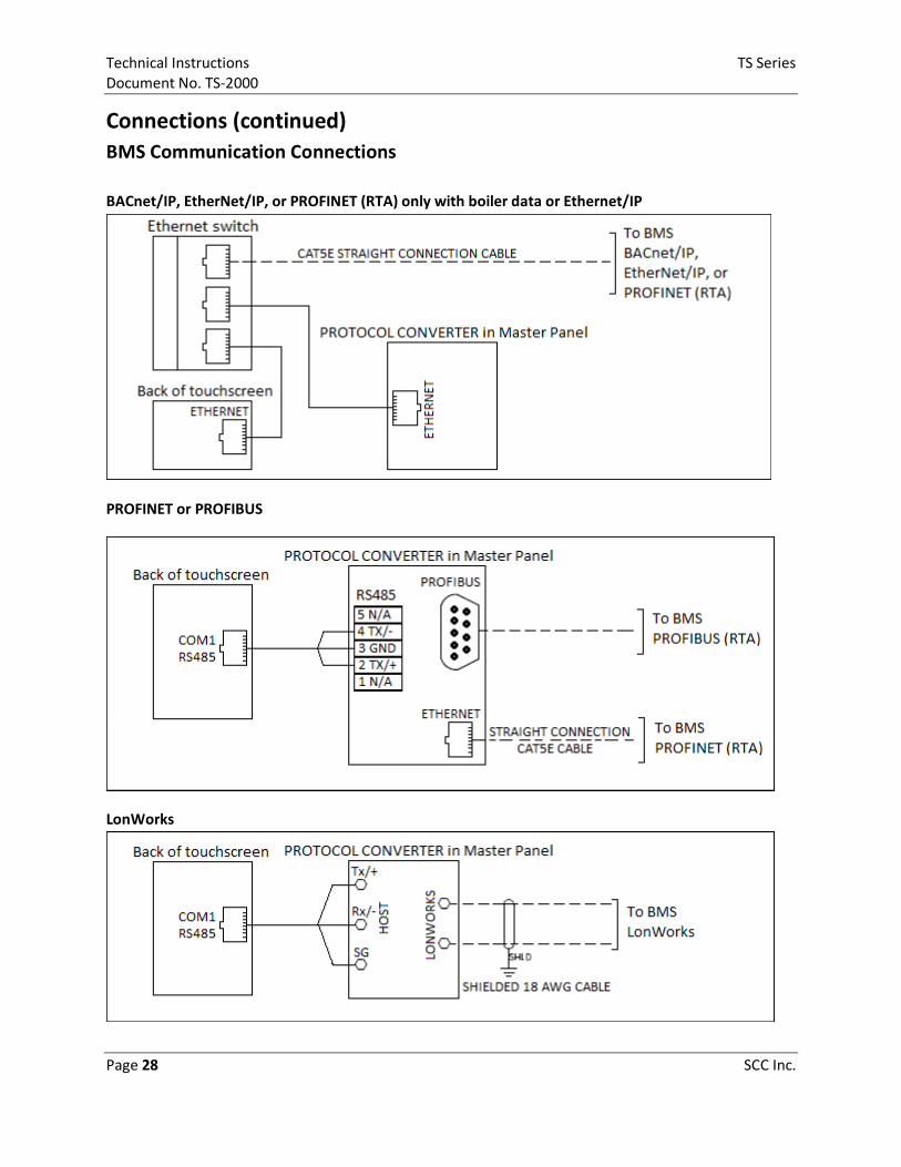
Connections (continued)
BMS Communication Connections
BACnet/IP, EtherNet/IP, or PROFINET (RTA) only with boiler data or Ethernet/IP
PROFINET or PROFIBUS
LonWorks

TS Series Technical Instructions
Document No. TS-2000
SCC Inc. Page 29
Enclosure Parts Description
Enclosure Dimensions
A. 24 VDC PLC normal indicator light
B. Main 120 VAC lockable disconnect handle
C. 7”, 10” or 12” Schneider touchscreen
D. Ethernet switch, number of ports dependent upon product part number
E. Circulating pump and isolation valves output relays, only if circulating pump controls option (Y) is selected for
hot water boilers (Application H, W, or Z)
F. 24 VDC enclosure terminals
G. 24 VDC power supply
H. Circuit breaker
I. 120 VAC power terminals
J. 120 VAC main disconnect with UL lock
K. Ground lugs
L. Schneider Programmable Logic Controller (PLC)
M. Analog input module, standard for (Application S, R, or U); included if analog option (A) is selected for hot water
boilers (Application H, W, or Z)
N. RTD input module, standard for hot water boilers (Application H, W, or Z); included if RTD option (T) is selected
for steam boilers (Application S, R, or U)
O. Monitored value discrete output relays
P. General and analog high/low alarm relays
Q. Analog output field terminals
R. Circulating pumps control field terminals, standard for hot water boilers only (Application H, W, or Z)
S. General, PLC normal, high, and low analog input alarm field terminals
T. Monitored value discrete output field terminals
U. Override, remote set point, and remote disable field terminals
V. Circulating pump proven field terminals for hot water boilers only (Application H, W, or Z)
W. RTD input field terminals , standard for hot water boilers (Application H, W, or Z), optional for steam boilers
(Application S, R, or U)
X. Analog input field terminals, standard for steam boilers (Application S, R, or U), included if analog option (A) is
selected for hot water boilers (Application H, W, or Z)
Y. BMS interface module for communications other than Modbus (Options B, L, or M)
Z. Digital Input terminals
AA. Serial RS-485 Communication Terminals
2

Technical Instructions TS Series
Document No. TS-2000
SCC Inc. Your feedback is important to us. If you have Document No. TS-2000 1250 Lunt Avenue comments about this document, please send them Country of Origin: US
Elk Grove Village, IL 60007 to [email protected] Page 30
U.S.A.
Enclosure Dimensions
Dimensions in inches; millimeters in brackets
Back
Side (NEMA 1/NEMA 4X) Side (NEMA 12 with cover) Information in this publication is based on current specifications. The company reserves the right to make changes in specifications and models as design improvements are introduced. Product or company names mentioned herein may be the trademarks of their respective owners. © 2009 SCC Inc.