tsm14poe - applied-motion.com
TRANSCRIPT
TSM14POEStepSERVO Integrated Motor
Hardware Manual
920-0153 A 01/23/2020

2
TSM14POE Hardware Manual920-0153 A01/23/2020
Contents1 Introduction ........................................................................4
1.1 Features .................................................................................41.2 Block Diagram .......................................................................51.3 Safety Instructions .................................................................6
2 Getting Started ..................................................................72.1 Installing Software .................................................................72.2 Mounting the Hardware .........................................................72.3 Choosing a Power Supply .....................................................83.2 Connecting the Drive to Your PC using Ethernet ...................9
4 Troubleshooting .................................................................17
5 Reference Materials ..........................................................185.1 Mechanical Outlines ..............................................................185.2 Technical Specifications .........................................................195.3 Torque-Speed Curves ............................................................20
6 Contacting Applied Motion Products ..................................22

3
TSM14POE Hardware Manual 920-0153 A01/23/2020
TSM14POE Models Available
ModelConnector Communication
RJ45 M12 8 Pin X-Coded EtherNet/IP
TSM14POE3M-IPEJ
TSM14POE3M-IPEM

4
TSM14POE Hardware Manual920-0153 A01/23/2020
1 IntroductionThank you for selecting the Applied Motion Products TSM14POE StepSERVO Integrated Motor. The TSM line of integrated step-servo motors combines servo technology with an integrated motor to create a product with exceptional features and broad capability. We hope our commitment to performance, quality and economy will result in a successful motion control project.
1.1 Features• Programmable, digital servo driver and closed-loop step motor in an integrated package• Communication and power over Ethernet (POE+). Powered switch or injector required.
Recommended injector: BV Tech POE-I100G (AMP part number 1000-382)• Control Modes:
Torque Control• Commanded
Velocity Control• Commanded Velocity (Jogging)
Position Control• Serial Commanded Position
Q Programming• Executes stored Q programs• Conditional processing & multi-tasking• Math functions, register manipulation
• Communications:Ethernet TCP/IP or UDP, EtherNet/IP industrial networking , Modbus/TCP
• 1024 line (4096 count/turn) encoder feedback• Available torque:
Up to 29 oz-in continuous (37 oz-in boost) • Technological advances:
Full servo control, Closed loopEfficient, Accurate, Fast, SmoothIntelligent, CompactSingle cable for power and communication

5
TSM14POE Hardware Manual 920-0153 A01/23/2020
1.2 Block Diagram
Block Diagram
MOSFETPWMPower
Amplifier
VoltageTempDetect
OverCurrentDetect
motor
encoder
5 Volt DCPower Supply
DSPDriver
Controller
3.3VDCInternalLogic
Supply
TSM14POE 42.5-57 VDC
IP Address Selection
Ethernet
Com
mC
onn100 Mbit Ethernet
POE+ power
34210 F EDCBA
98765
Status

6
TSM14POE Hardware Manual920-0153 A01/23/2020
1.3 Safety InstructionsOnly qualified personnel should transport, assemble, install, operate, or maintain this equipment. Properly qualified personnel are persons who are familiar with the transport, assembly, installation, operation, and maintenance of motors, and who meet the appropriate qualifications for their jobs.
To minimize the risk of potential safety problems, all applicable local and national codes regulating the installation and operation of equipment should be followed. These codes may vary from area to area and it is the responsibility of the operating personnel to determine which codes should be followed, and to verify that the equipment, installation, and operation are in compliance with the latest revision of these codes.
Equipment damage or serious injury to personnel can result from the failure to follow all applicable codes and standards. Applied Motion Products does not guarantee the products described in this publication are suitable for a particular application, nor do they assume any responsibility for product design, installation, or operation.
• Read all available documentation before assembly and operation. Incorrect handling of the products referenced in this manual can result in injury and damage to persons and machinery. All technical information concerning the installation requirements must be strictly adhered to.
• It is vital to ensure that all system components are connected to earth ground. Electrical safety is impossible without a low-resistance earth connection.
• This product contains electrostatically sensitive components that can be damaged by incorrect handling. Follow qualified anti-static procedures before touching the product.
• During operation keep all covers and cabinet doors shut to avoid any hazards that could possibly cause severe damage to the product or personal health.
• During operation, the product may have components that are live or have hot surfaces.
Be alert to the potential for personal injury. Follow recommended precautions and safe operating practices emphasized with alert symbols. Safety notices in this manual provide important information. Read and be familiar with these instructions before attempting installation, operation, or maintenance. The purpose of this section is to alert users to the possible safety hazards associated with this equipment and the precautions necessary to reduce the risk of personal injury and damage to equipment. Failure to observe these precautions could result in serious bodily injury, damage to the equipment, or operational difficulty.

7
TSM14POE Hardware Manual 920-0153 A01/23/2020
2 Getting StartedThe following items are needed:
• A POE+ rated Ethernet switch or injector.
Recommended:
- Injector: BV Tech POE-I100G (Applied Motion P/N 1000-382).
- Switch: BV Tech POE-SW801.
• A PC running Microsoft Windows XP, Vista, or Windows 7 or 8 or 10. 32 or 64 bits.
• A CAT6 network cable (not included).
2.1 Installing SoftwareBefore utilizing the TSM14POE StepSERVO Integrated Motor and Step-Servo Quick Tuner Software in an application, the following steps are necessary:
• Download and install the Step-Servo Quick Tuner software.
• If you intend to connect the drive directly to your PC, configure your computer to use IP address 10.10.10.11. (For instructions on connecting your TSM drive to a local area network (LAN), please consult the appropriate hardware manual).
• On the TSM drive, select switch position 0, which will assign IP address 10.10.10.10. (See the hardware manual for further details on selecting IP addresses for the drive and PC).
• Launch the software by clicking: Start / All Programs / Applied Motion Products / Step-Servo Quick Tuner or use the desktop shortcut.
• Connect the TSM to the injector or power switch using a Ethernet cable.
• Click “Connect” in the software. The drive model and firmware revision should be automatically displayed in the Step-Servo Quick Tuner software.
2.2 Mounting the HardwareAs with any step motor, the TSM14POE must be mounted so as to provide maximum heat sinking and airflow. Keep enough space around the Integrated Motor to allow for airflow.
• Never use the drive where there is no airflow or where other devices cause the surrounding air to be more than 40°C (104°F).
• Never put the drive where it can get wet.
• Never use the drive where metal or other electrically conductive particles can infiltrate the drive.
• Always provide airflow around the drive.

8
TSM14POE Hardware Manual920-0153 A01/23/2020
2.3 Choosing a Power SupplyPlease choose a POE+ (IEEE 802.3at Type 2) compatible injector or powered switch.
Modes A and B are supported. Recommended injector: BV Tech POE-I100G (AMP part number 1000-382). Recommended powered Ethernet switch: BV Tech POE-SW801.
9
TSM14POE Hardware Manual 920-0153 A01/23/2020
3.2 Connecting the Drive to Your PC using EthernetThis process requires three steps
• Physically connect the drive to your network (or directly to the PC).• Set the drive’s IP address.• Set the appropriate networking properties on your PC.
Addresses, Subnets, and Ports
Every device on an Ethernet network must have a unique IP address. In order for two devices to communicate with each other, they must both be connected to the network and they must have IP addresses that are on the same subnet. A subnet is a logical division of a larger network. Members of one subnet are generally not able to communicate with members of another unless they are connected through special network equipment (e.g. router). Subnets are defined by the choices of IP addresses and subnet masks.
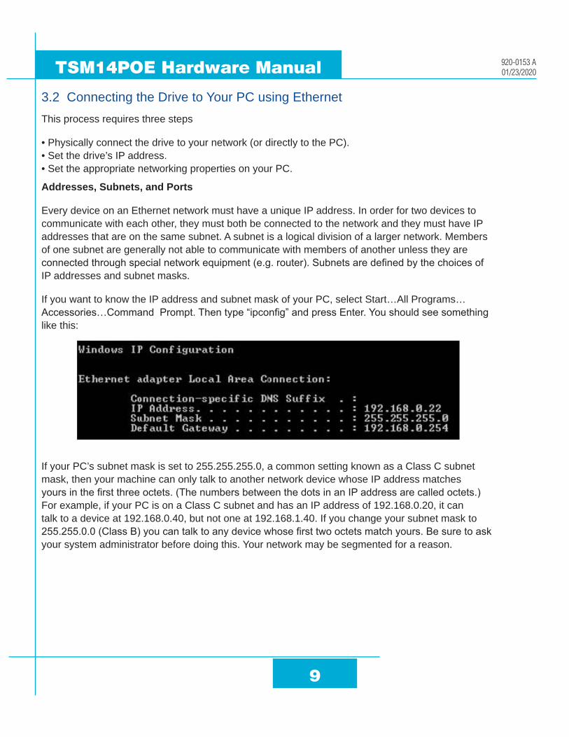
If you want to know the IP address and subnet mask of your PC, select Start…All Programs…Accessories…Command Prompt. Then type “ipconfig” and press Enter. You should see something like this:
If your PC’s subnet mask is set to 255.255.255.0, a common setting known as a Class C subnet mask, then your machine can only talk to another network device whose IP address matches yours in the first three octets. (The numbers between the dots in an IP address are called octets.) For example, if your PC is on a Class C subnet and has an IP address of 192.168.0.20, it can talk to a device at 192.168.0.40, but not one at 192.168.1.40. If you change your subnet mask to 255.255.0.0 (Class B) you can talk to any device whose first two octets match yours. Be sure to ask your system administrator before doing this. Your network may be segmented for a reason.

10
TSM14POE Hardware Manual920-0153 A01/23/2020
Your drive includes a 16 position rotary switch for setting its IP address. The factory default address for each switch setting is shown in the table on the next page.
Settings 1 through E can be changed using the Step-Servo Quick Tuner software. Setting 0 is always “10.10.10.10”, the universal recovery address. If someone were to change the other settings and not write it down or tell anyone (I’m not naming names here, but you know who I’m talking about) then you will not be able to communicate with your drive. The only way to “recover” it is to use the universal recovery address.
Rotary Switch IP Address0 10.10.10.101 192.168.1.102 192.168.1.203 192.168.1.304 192.168.0.405 192.168.0.506 192.168.0.607 192.168.0.708 192.168.0.809 192.168.0.90A 192.168.0.100B 192.168.0.110C 192.168.0.120D 192.168.0.130E 192.168.0.140F DHCP
Setting F is “DHCP”, which commands the drive to get an IP address from a DHCP server on the network. The IP address automatically assigned by the DHCP server may be “dynamic” or “static” depending on how the administrator has configured DHCP. The DHCP setting is reserved for advanced users.
Your PC, or any other device that you use to communicate with the drive, will also have a unique address.
On the drive, switch settings 1 through E use the standard class B subnet mask (i.e. “255.255.0.0”). The mask for the universal recovery address is the standard class A (i.e. “255.0.0.0”).
One of the great features of Ethernet is the ability for many applications to share the network at the same time.

11
TSM14POE Hardware Manual 920-0153 A01/23/2020
Ports are used to direct traffic to the right application once it gets to the right IP address. The UDP eSCL port in our drives is 7775. To send and receive commands using TCP, use port number 7776. You’ll need to know this when you begin to write your own application. You will also need to choose an open (unused) port number for your application. Our drive doesn’t care what that is; when the first command is sent to the drive, the drive will make note of the IP address and port number from which it originated and direct any responses there. The drive will also refuse any traffic from other IP addresses that is headed for the eSCL port. The first application to talk to a drive “owns” the drive. This lock is only reset when the drive powers down.
If you need help choosing a port number for your application, you can find a list of commonly used port numbers at http://www.iana.org/assignments/port-numbers.
One final note: Ethernet communication can use one or both of two “transport protocols”: UDP and TCP. eSCL commands can be sent and received using either protocol. UDP is simpler and more efficient than TCP, but TCP is more reliable on large or very busy networks where UDP packets might occasionally be dropped.
Option 1: Connect a Drive to Your Local Area Network
If you have a spare port on a switch or router and if you are able to set your drive to an IP address that is compatible with your network, and not used by anything else, this is a simple way to get connected. This technique also allows you to connect multiple drives to your PC. If you are on a corporate network, please check with your system administrator before connecting anything new to the network. He or she should be able assign you a suitable address and help you get going.
If you are not sure which addresses are already used on your network, you can find out using “Angry IP scanner”, which can be downloaded free from http://www.angryip.org/w/Download. But be careful: an address might appear to be unused because a computer or other device is currently turned off. And many networks use dynamic addressing where a DHCP server assigns addresses “on demand”. The address you choose for your drive might get assigned to something else by the DHCP server at another time.
PC NIC
LAN DRIVE POWEREDSWITCH

12
TSM14POE Hardware Manual920-0153 A01/23/2020
Once you’ve chosen an appropriate IP address for your drive, set the rotary switch according the address table above. If none of the default addresses are acceptable for your network, you can enter a new table of IP addresses using Step-Servo Quick Tuner software. If your network uses addresses starting with 192.168.0, the most common subnet, you will want to choose an address from switch settings 4 through E. Another common subnet is 192.168.1. If your network uses addresses in this range, the compatible default selections are 1, 2 and 3.
If your PC address is not in one of the above private subnets, you will have to change your subnet mask to 255.255.0.0 in order to talk to your drive. To change your subnet mask:
1. On Windows XP, right click on “My Network Places” and select Properties. On Windows 7, click Computer.
Scroll down the left pane until you see “Network”. Right click and select Properties. Select “Change adapter settings”.
2. You should see an icon for your network interface card (NIC). Right click and select Properties.
3. Scroll down until you see “Internet Properties (TCP/IP)”. Select this item and click the Properties button. On Windows 7 and Vista, look for “(TCP/IPv4)”.
4. If the option “Obtain an IP address automatically” is selected, your PC is getting an IP address and a subnet mask from the DHCP server. Please cancel this dialog and proceed to the next section of this manual: “Using DHCP”.

13
TSM14POE Hardware Manual 920-0153 A01/23/2020
5. If the option “Use the following IP address” is selected, life is good. Change the subnet mask to “255.255.0.0” and click OK.
Using DCHP
If you want to use your drive on a network where all or most of the devices use dynamic IP addresses supplied by a DHCP server, set the rotary switch to “F”. When the drive is connected to the network and powered on, it will obtain an IP address and a subnet mask from the server that is compatible with your PC. The only catch is that you won’t know what address the server assigns to your drive. Step-Servo Quick Tuner software can find your drive using the Drive Discovery feature, as long as your network isn’t too large. With the drive connected to the network and powered on, select Drive Discovery from the Drive Tools menu.
You will see a dialog such as this:
Normally, Drive Discovery will only detect one network interface card (NIC), and will select it automatically. If you are using a laptop and have both wireless and wired network connections, a second NIC may appear.

14
TSM14POE Hardware Manual920-0153 A01/23/2020
Please select the NIC that you use to connect to the network to which you’ve connected your drive. Then click OK. Drive Discovery will notify you as soon as it has detected a drive.
If you think this is the correct drive, click Yes. If you’re not sure, click Not Sure and Drive Discovery will look for additional drives on your network. Once you’ve told Drive Discovery which drive is yours, it will automatically enter that drive’s IP address in the IP address text box so that you are ready to communicate.
Option 2: Connect a Drive Directly to Your PC
It doesn’t get much simpler than this:
1. Connect one end of a CAT6 Ethernet cable into the LAN card (NIC) on your PC and the other into the drive.
You don’t need a special “crossover cable”; the drive will automatically detect the direct connection and make the necessary physical layer changes.
2. Set the IP address on the drive to “10.10.10.10” by setting the rotary switch at “0”.
3. To set the IP address of your PC:
a. On Windows XP, right click on “My Network Places” and select properties.
b. On Windows 7, click Computer. Scroll down the left pane until you see “Network”. Right click and select properties. Select “Change adapter settings”.

15
TSM14POE Hardware Manual 920-0153 A01/23/2020
4. You should see an icon for your network interface card (NIC). Right click and select properties.
a. Scroll down until you see “Internet Properties (TCP/IP)”. Select this item and click the Properties
button.
b. On Windows 7 and Vista, look for “(TCP/IPv4)”.
5. Select the option “Use the following IP address”. Then enter the address “10.10.10.11”. This will give your PC an IP address that is on the same subnet as the drive. Windows will know to direct any traffic intended for the drive’s IP address to this interface card.
6. Next, enter the subnet mask as “255.255.255.0”.
7. Be sure to leave “Default gateway” blank. This will prevent your PC from looking for a router on this subnet.
8. Because you are connected directly to the drive, anytime the drive is not powered on, your PC will annoy you with a small message bubble in the corner of your screen saying “The network cable is unplugged.”

16
TSM14POE Hardware Manual920-0153 A01/23/2020
Option 3: Use Two Network Interface Cards (NICs)
This technique allows you to keep your PC connected to your LAN, but keeps the drive off the LAN, preventing possible IP conflicts or excessive traffic.
1. If you use a desktop PC and have a spare card slot, install a second NIC and connect it directly to the drive using a CAT6 cable. You don’t need a special “crossover cable”; the drive will automatically detect the direct connection and make the necessary physical layer changes.
2. If you use a laptop and only connect to your LAN using wireless networking, you can use the built-in RJ45 Ethernet connection as your second NIC.
3. Set the IP address on the drive to “10.10.10.10” by setting the rotary switch at “0”.
4. To set the IP address of the second NIC:
a. On Windows XP, right click on “My Network Places” and select properties.
b. On Windows 7, click Computer. Scroll down the left pane until you see “Network”. Right click and select properties. Select “Change adapter settings”.
5. You should see an icon for your newly instated NIC. Right click again and select properties.
a. Scroll down until you see “Internet Properties (TCP/IP)”. Select this item and click the Properties button.
b. On Windows 7 and Vista, look for “(TCP/IPv4)”.
6. Select the option “Use the following IP address”. Then enter the address “10.10.10.11”. This will give your PC an IP address that is on the same subnet as the drive. Windows will know to direct any traffic intended for the drive’s IP address to this interface card.
7. Next, enter the subnet mask as “255.255.255.0”. Be sure to leave “Default gateway” blank. This will prevent your PC from looking for a router on this subnet.
8. Because you are connected directly to the drive, anytime the drive is not powered on your PC will annoy you with a small message bubble in the corner of your screen saying “The network cable is unplugged.”

17
TSM14POE Hardware Manual 920-0153 A01/23/2020
4 TroubleshootingLED Error Codes
The TSM14POE uses red and green LEDs to indicate status. When the motor is enabled, the green LED flashes slowly. When the green LED is solid, the motor is disabled. Errors are indicated by combinations of red and green flashes as shown below. This feature can be disabled for certain warnings but not for alarms. See Step-Servo Quick Tuner software help manual on how to do this and which warnings may be masked.
Code Error
solid green
flashing green
1 red, 1 green
1 red, 2 green
2 red, 1 green
2 red, 2 green
3 red, 1 green
3 red, 2 green
3 red, 3 green
4 red, 1 green
4 red, 2 green
7 red, 1 green
4 red, 3 green
5 red, 1 green
5 red, 2 green
6 red, 1 green
6 red, 2 green
7 red, 2 green
motor disabled
motor enabled
position limit
drive disabled
ccw limit
cw limit
over temperature
internal voltage
non-volatile memory error
over voltage
under voltage
non-volatile double error
over current
peak current time limit
open winding
encoder failure
communication error
save failed
Items in bold are Drive Faults.
18
TSM14POE Hardware Manual920-0153 A01/23/2020
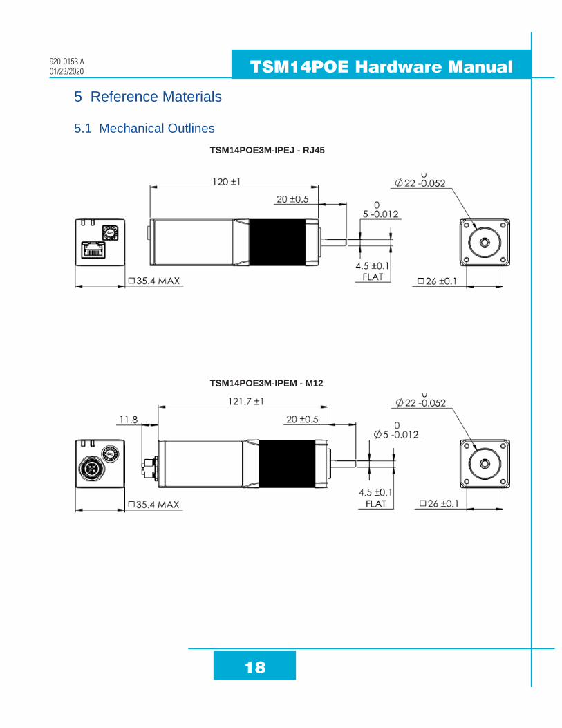
5 Reference Materials
5.1 Mechanical Outlines TSM14POE3M-IPEJ - RJ45
TSM14POE3M-IPEM - M12

19
TSM14POE Hardware Manual 920-0153 A01/23/2020
5.2 Technical Specifications
Power Amplifier
Amplifier Type Dual H-Bridge, 4 Quadrant
Current Control 4 state PWM at 20 KHz
Output Torque Up to 27 oz-in continuous, 32 oz-in peak
Power Supply POE+ injector or powered switch required
Protection Over-voltage, under-voltage, over-temp, motor/wiring shorts (phase-to-phase, phase-to-ground)
Controller
Encoder Resolution 4096 counts/rev
Speed Range See torque-speed curves
Filters PID filter, Notch filter
Non-Volatile Storage Configurations are saved in FLASH memory on-board the DSP
Modes of Operation EtherNet/IP (implicit and explicit messaging) or Modbus/TCP, streaming commands(SCL), stored Q program execution
CommunicationInterface 100 Mbit Ethernet with auto crossover and POE+ (IEEE 802.3at Type 2)
Physical
Ambilent Temperature 0 to 40°C (32 to 104°F) When mounted to a suitable heatsink
Humdity 90% Max., non-condensing
Mass 400 g
Rotor Inertia 35 g-cm2

20
TSM14POE Hardware Manual920-0153 A01/23/2020
5.3 Torque-Speed CurvesNote: Torque curves were measured at 4096 steps/rev.
-
5
10
15
20
25
30
35
40
0 5 10 15 20 25 30 35 40 45 50
oz-
in
rev/sec
TSM14POE Speed-Torque Curve
Peak
Continuous
Peak
Continuous

21
TSM14POE Hardware Manual 920-0153 A01/23/2020
Further reading:
2D outline drawings:
RJ45 version: https://www.applied-motion.com/products/stepservo-integrated-motors/tsm14poe3m-ipej
M12 version: https://www.applied-motion.com/products/stepservo-integrated-motors/tsm14poe3m-ipem
3D solid models:
RJ45 version: https://www.applied-motion.com/products/stepservo-integrated-motors/tsm14poe3m-ipej
M12 version: https://www.applied-motion.com/products/stepservo-integrated-motors/tsm14poe3m-ipem
Communication: Host Command Reference Manual www.applied-motion.com/hcr
What is POE? https://www.applied-motion.com/news/2019/10/what-poe
Data sheet: https://www.applied-motion.com/sites/default/files/TSM14POE-Integrated-Motor-Datasheet-925-0024B.pdf

22
TSM14POE Hardware Manual920-0153 A01/23/2020
6 Contacting Applied Motion Products404 Westridge Dr.Watsonville, CA 95076, USA1-800-525-1609www.applied-motion.com