tspp version 1.5 security policy - nist · dsa in the digital signature ... this document is a...
TRANSCRIPT
Thales e-Security TSPP Security Policy
ASEC0942.001H 07 March 2013
i
TSPP
Version 1.5
Security Policy
Product Version Details:
Part Name Hardware Version Firmware Version
TSPP-A 1.0, 1.0.1, 1.0.2, 1.0.3, 1.0.4 or 1.0.5 1.10.2
TSPP-B 1.0, 1.0.1, 1.0.2, 1.0.3, 1.0.4 or 1.0.5 1.10.2
Thales e-Security
Meadow View House
Crendon Industrial Estate
Long Crendon
AYLESBURY
HP18 9EQ
United Kingdom
Tel: +44 (0)1844 201800
Fax: +44 (0)1844 208550
FIPS 140-2 Non-proprietary Security Policy
This document may be copied whole and intact including copyright notice.
Thales e-Security TSPP Security Policy
ASEC0942.001H 07 March 2013
1
Contents 1. Abbreviations .......................................................................................................................... 2
2. Reference documents ............................................................................................................. 2
3. Introduction............................................................................................................................. 3
4. Ports and Interfaces ............................................................................................................... 5
5. Identification and Authentication Policy ............................................................................ 6
5.1 Other Security-Relevant Information ............................................................................ 7
6. Access Control Policy ............................................................................................................. 8
6.1 Roles .................................................................................................................................... 8
6.2 Services ................................................................................................................................ 8
6.2.1 Module Status .......................................................................................................... 8
6.2.2 Self-Tests .................................................................................................................. 9
6.3 Cryptographic Keys and Other CSPs ............................................................................ 9
6.4 Services that Operators are Authorized to Perform (within each Role) ................... 9
7. Physical Security Policy ....................................................................................................... 10
7.1 Actions Required to Ensure Security is Maintained .................................................. 10
7.2 Tamper-evident labels .................................................................................................... 10
8. Error Responses ................................................................................................................... 11
8.1 Power Up Test Errors ..................................................................................................... 11
8.2 Conditional Test Errors .................................................................................................. 12
9. Mitigation of Other Attacks Policy .................................................................................... 12
9.1 Intrusion, Movement, Temperature and Voltage ....................................................... 12
9.2 Fault Induction Attacks .................................................................................................. 13
Figures Figure 1: TSPP-B ............................................................................................................................ 3
Figure 2: Label positioning .......................................................................................................... 11
Figure 3: Close-up of Thales tamper-evident label .................................................................. 11
Tables Table 3-1 Module Security Level Specification ........................................................................... 4
Table 4-1 Ports and Interface Description ................................................................................... 5
Table 6-1 Roles and Required Identification and Authentication ........................................... 8
Table 6-2 Cryptographic Key and CSP ....................................................................................... 9
Thales e-Security TSPP Security Policy
ASEC0942.001H 07 March 2013
2
1. Abbreviations
Approved FIPS-Approved
CA Certificate Authority
CSP Critical Security Parameter
DSA Digital Signature Algorithm
Flash Electrically erasable non-volatile memory
FIPS Federal Information Processing Standard
FIPS 140-2 FIPS PUB 140-2 (Ref: FIPS 140-2)
FPGA Field Programmable Gate Array
KAT Known Answer Test
PCIe PCI Express
RAM Random Access Memory
SHA Secure Hash Algorithm
SHA-256 SHA producing a 256-bit message digest
TSPP Thales Secure Processing Platform (multi-chip embedded cryptographic module)
2. Reference documents
FIPS 140-2 Federal Information Processing Standards Publication, Security
Requirements for Cryptographic Modules, FIPS PUB 140-2
FIPS 180-3 Federal Information Processing Standards Publication, Secure Hash
Standard, FIPS PUB 180-3, which defines the SHA-256 hash, used by
DSA in the Digital Signature Standard (Ref: FIPS 186-3)
FIPS 186-3 Federal Information Processing Standards Publication, Digital Signature
Standard, FIPS PUB 186-3, which defines DSA (Digital Signature
Algorithm)
Thales e-Security TSPP Security Policy
ASEC0942.001H 07 March 2013
3
3. Introduction
This document is a security policy for the TSPP which is a Thales e-Security (Thales) multi-
chip embedded cryptographic module. The TSPP provides functionality for the secure loading
and/or upgrading of applications used in a range of Thales products.
The module ensures that only applications that have been signed by Thales can be loaded into
the module.
The module ensures the integrity of any application that is loaded into it. It will only allow an
application to be loaded if it has been signed by a private key that has been generated by the
vendor. The signature is verified using a FIPS Approved signature verification algorithm and the
public key corresponding to the vendor’s private key. This Approved algorithm and the public
key are securely stored in the module.
The module implements the following FIPS Approved algorithms:
DSA (Ref: FIPS 186-3)
SHA-256 (Ref: FIPS 180-3)
SHA-256 is used as the hash function for the DSA signature verification algorithm.
The circuitry within the module’s cryptographic boundary is protected by robust metal covers.
TSPP contains a protected non-volatile memory that can be used by applications to contain
confidential key material.
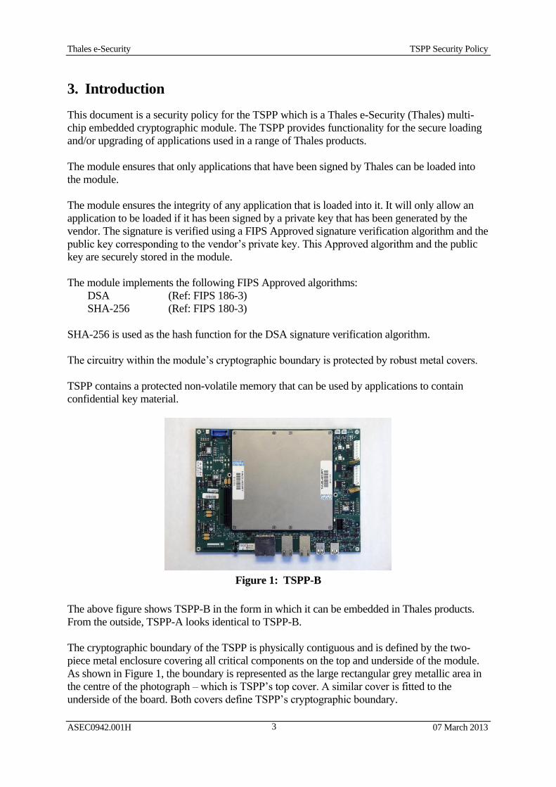
Figure 1: TSPP-B
The above figure shows TSPP-B in the form in which it can be embedded in Thales products.
From the outside, TSPP-A looks identical to TSPP-B.
The cryptographic boundary of the TSPP is physically contiguous and is defined by the two-
piece metal enclosure covering all critical components on the top and underside of the module.
As shown in Figure 1, the boundary is represented as the large rectangular grey metallic area in
the centre of the photograph – which is TSPP’s top cover. A similar cover is fitted to the
underside of the board. Both covers define TSPP’s cryptographic boundary.
Thales e-Security TSPP Security Policy
ASEC0942.001H 07 March 2013
4
Circuitry outside the covers performs no sensitive operations, and mainly consists of power
supplies and interfacing electronics.
The module generates messages via a serial interface that indicates that the module is in a FIPS
Approved mode.
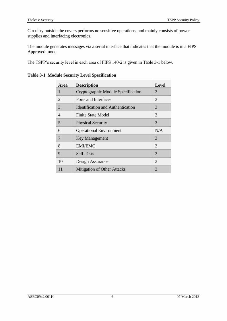
The TSPP’s security level in each area of FIPS 140-2 is given in Table 3-1 below.
Table 3-1 Module Security Level Specification
Area Description Level
1 Cryptographic Module Specification 3
2 Ports and Interfaces 3
3 Identification and Authentication 3
4 Finite State Model 3
5 Physical Security 3
6 Operational Environment N/A
7 Key Management 3
8 EMI/EMC 3
9 Self-Tests 3
10 Design Assurance 3
11 Mitigation of Other Attacks 3
Thales e-Security TSPP Security Policy
ASEC0942.001H 07 March 2013
5
4. Ports and Interfaces
The TSPP’s circuit board has many physical ports; but the TSPP’s FIPS validated firmware uses
only one physical port, a serial interface (UART0), used by all its logical communication
interfaces. This UART supports the input of data and control, and its output provides data and
status. The TSPP’s other interfaces are physically capable of both data input and data output, or
for conveying control and status to and from the module; but none of them are used or supported
by the TSPP’s validated firmware.
The TSPP has a variety of power interfaces including one that is designed to supply battery
power to security circuitry in the absence of mains-derived power.
There are two variants of TSPP. The TSPP-A variant includes an FPGA co-processor and other
associated circuit elements, including an additional PCIe interface, that are not present in the
TSPP-B variant. Both variants operate with the same FIPS validated firmware.
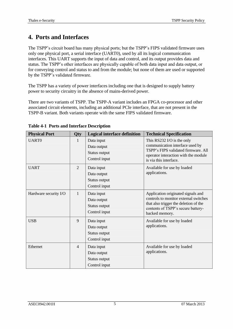
Table 4-1 Ports and Interface Description
Physical Port Qty Logical interface definition Technical Specification
UART0 1 Data input
Data output
Status output
Control input
This RS232 I/O is the only
communication interface used by
TSPP’s FIPS validated firmware. All
operator interaction with the module
is via this interface.
UART 2 Data input
Data output
Status output
Control input
Available for use by loaded
applications.
Hardware security I/O 1 Data input
Data output
Status output
Control input
Application originated signals and
controls to monitor external switches
that also trigger the deletion of the
contents of TSPP’s secure battery-
backed memory.
USB 9 Data input
Data output
Status output
Control input
Available for use by loaded
applications.
Ethernet 4 Data input
Data output
Status output
Control input
Available for use by loaded
applications.
Thales e-Security TSPP Security Policy
ASEC0942.001H 07 March 2013
6
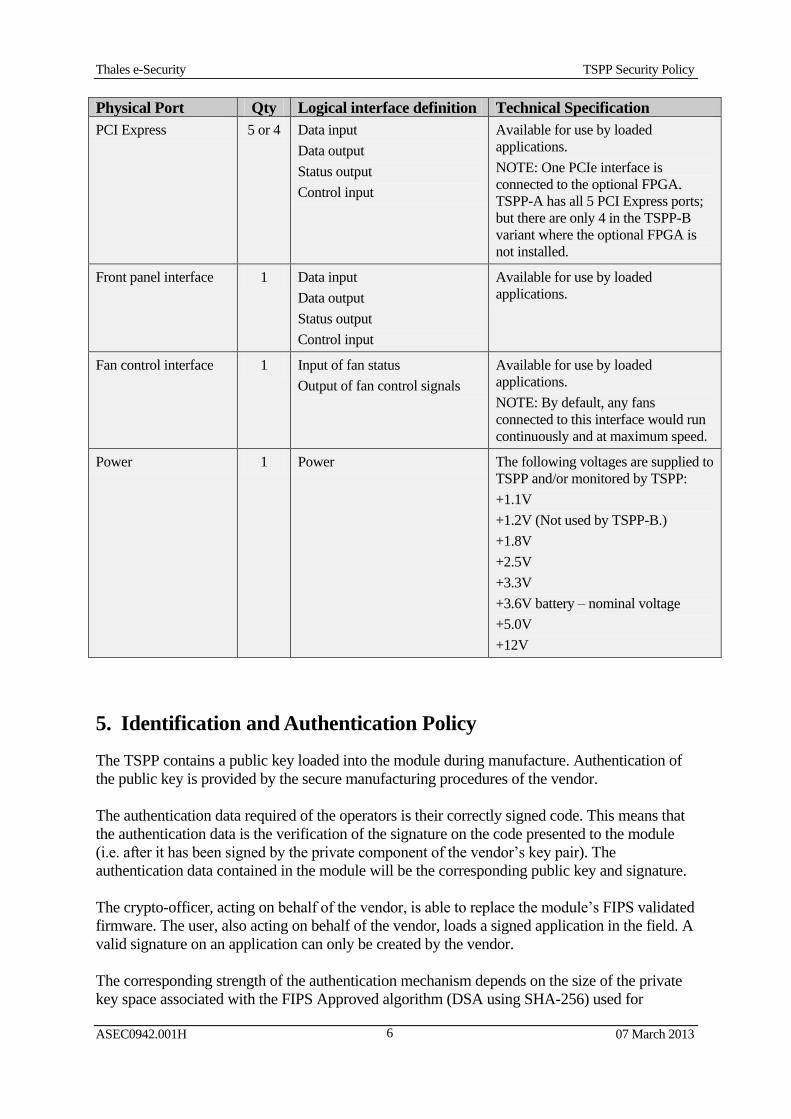
Physical Port Qty Logical interface definition Technical Specification
PCI Express 5 or 4 Data input
Data output
Status output
Control input
Available for use by loaded
applications.
NOTE: One PCIe interface is
connected to the optional FPGA.
TSPP-A has all 5 PCI Express ports;
but there are only 4 in the TSPP-B
variant where the optional FPGA is
not installed.
Front panel interface 1 Data input
Data output
Status output
Control input
Available for use by loaded
applications.
Fan control interface 1 Input of fan status
Output of fan control signals
Available for use by loaded
applications.
NOTE: By default, any fans
connected to this interface would run
continuously and at maximum speed.
Power 1 Power The following voltages are supplied to
TSPP and/or monitored by TSPP:
+1.1V
+1.2V (Not used by TSPP-B.)
+1.8V
+2.5V
+3.3V
+3.6V battery – nominal voltage
+5.0V
+12V
5. Identification and Authentication Policy
The TSPP contains a public key loaded into the module during manufacture. Authentication of
the public key is provided by the secure manufacturing procedures of the vendor.
The authentication data required of the operators is their correctly signed code. This means that
the authentication data is the verification of the signature on the code presented to the module
(i.e. after it has been signed by the private component of the vendor’s key pair). The
authentication data contained in the module will be the corresponding public key and signature.
The crypto-officer, acting on behalf of the vendor, is able to replace the module’s FIPS validated
firmware. The user, also acting on behalf of the vendor, loads a signed application in the field. A
valid signature on an application can only be created by the vendor.
The corresponding strength of the authentication mechanism depends on the size of the private
key space associated with the FIPS Approved algorithm (DSA using SHA-256) used for
Thales e-Security TSPP Security Policy
ASEC0942.001H 07 March 2013
7
generating and verifying the digital signatures. Since the module uses only these FIPS Approved
algorithms (see http://csrc.nist.gov/groups/STM/cavp/index.html) the size of the key space
provides an extremely high level of security for the authentication mechanism.
With the vendor’s public key of 2048 bits, DSA has an equivalent security strength of 112 bits.
The possibility that a random attempt to directly use the authentication mechanism of TSPP will
succeed or that a false acceptance will occur is therefore (significantly) less than one in
1,000,000 as required by FIPS 140-2. It typically takes more than 3 seconds for each attempt to
use the authentication system. The probability that multiple random attempts to use the
authentication mechanism during a one-minute period will succeed or that a false acceptance
will occur is (significantly) less than one in 100,000 as required by FIPS 140-2. Therefore the
authentication mechanism within the TSPP is significantly stronger than the minimum required
for FIPS 140-2 validation.
5.1 Other Security-Relevant Information
All aspects of the TSPP’s design are controlled by Thales’ configuration management system.
TSPP only has a FIPS Approved mode of operation. TSPP uses only FIPS Approved algorithms
and it does not support non-FIPS Approved algorithms.
TSPP’s bootstrap is restricted to configuration and maintenance tasks such as reading and
updating configuration information and loading, erasing or updating loaded applications. When
a loaded application is present, TSPP’s bootstrap will normally provide basic system checks and
initialization, and then transfer control to the application.
FIPS 140-2 Approved security methods are used:
DSA (2048 bit modulus) (Certificate #375)
SHA-256 (Certificate #1071)
Thales e-Security TSPP Security Policy
ASEC0942.001H 07 March 2013
8
6. Access Control Policy
6.1 Roles
The module supports a crypto-officer and a user role. There is no maintenance role associated
with the module.
The types of each Role identified for TSPP are given in Table 6-1 below.
Table 6-1 Roles and Required Identification and Authentication
Role Type of Authentication Authentication Data
Crypto-Officer Identity based Signature Verification
User Identity based Signature Verification
The strength of authentication is described in Section 5.
6.2 Services
The only cryptographic service provided by the module is the loading of signed applications.
The FIPS validated firmware for loading of signed applications is normally referred to as a
“bootstrap”. If an attempt is made to load an application into the module, that application must
have been properly signed and there must be sufficient memory space within the TSPP to store
the loaded application.
Unauthenticated users may perform the following non-sensitive services:
Echo (Echoes back an input string)
Get version (Provides the version details of the bootstrap application)
Get CA code name (Provides the vendor’s name for the public/private key pair that is used
by the bootstrap when verifying the signature of the signed applications)
Restart system (Reboots the unit)
Set comms baud (Sets the baud rate for communication)
Deactivate an application (Prevents the bootstrap from recognizing the presence of an
application in the module and thus prevents the bootstrap from passing control to it)
Re-activate an application (Enables the bootstrap to negate the deactivation of an
application, again recognize its presence, and validate its integrity for the possibility of
passing control to it)
Read DSA issue number (Provides the version details of the DSA algorithm)
6.2.1 Module Status
The module generates the following message via its active serial interface to indicate that the
module is in a FIPS Approved mode:
THALES payShield 9000 Bootstrap Started
No valid application found
Other messages also identify errors and the progress of services.
Thales e-Security TSPP Security Policy
ASEC0942.001H 07 March 2013
9
If the module enters an error state, this will be accompanied by an error message at its active
serial interface; and then the module will typically restart automatically. If the module fails to
restart automatically, it is designed to do nothing else but wait indefinitely for a manual restart.
6.2.2 Self-Tests
There is a self-test service provided by the module, which is a FIPS Approved hash algorithm
test for validating the bootstrap. This self-test is performed at start-up and can be performed on
demand (i.e. during start-up after a service request to reboot the unit).
A Known Answer Tests (KAT) on the signature verification algorithm (DSA) is performed at
power up.
6.3 Cryptographic Keys and Other CSPs
The only cryptographic key directly employed by the module is the public key component of the
vendor’s key pair. This is stored in the non-volatile memory in the TSPP in plaintext form and is
protected by the physical security mechanisms associated with the TSPP. The vendor’s public
key never leaves TSPP. Disclosure of the vendor’s public key does not constitute a security risk
for the module since possession of the public key would not enable an attacker to sign
applications and thereby enter them into any TSPP module.
The cryptographic key stored in the TSPP, is identified in Table 6-2.
Table 6-2 Cryptographic Key
Keys/CSPs Description Size Generated/
Established Stored Zeroised
(Vendor) Public
Key
The public key of the key
pair used to authenticate
applications loaded into the
module.
DSA
(2048)
Generated externally
and loaded as part of
the manufacturing
process.
Non-volatile
memory –
Flash
When the key is
replaced by a
subsequent key.
Private keys are not directly employed by the bootstrap. A private key is used to sign an
application that is to be loaded into the module by the bootstrap. Private keys are never loaded
into the module, and are stored securely by the vendor.
There are no passwords or PINs associated with the operation of the module.
The only other security-relevant data are the signature algorithms used by the module. These
algorithms are publicly available and their disclosure would constitute no threat.
TSPP contains a protected battery-backed non-volatile memory (RAM) that can be used by
applications to contain secret data. The contents of this memory would be erased if the TSPP’s
covers are opened or where the TSPP detects and responds to some event that it interprets as a
possible attack.
6.4 Services that Operators are Authorized to Perform (within each Role)
The module supports two types of operators: “crypto-officer” and “user”. ”. The crypto-officer is
authorised to load the bootstrap, and the user is authorised to perform the application-loading
service provided by the module.
Thales e-Security TSPP Security Policy
ASEC0942.001H 07 March 2013
10
The operator will have access to the signed application that is to be loaded into the module.
Procedures should be implemented to ensure that only authorised operators are allowed to access
the signed application. However the operator will not have direct access to the particular private
key that has been used to sign the application. This means that the operator would not be able to
sign another application and load it into the module. The signing of the application must be
authorised by the vendor.
The operator is also authorised to perform other services provided by the module (see
Section 6.2 above).
TSPP does not support concurrent operators. An operator cannot change roles without re-
authenticating.
7. Physical Security Policy
7.1 Actions Required to Ensure Security is Maintained
The TSPP is a multiple-chip embedded cryptographic module consisting of production grade
components intended to meet FIPS 140-2 Level 3. It does not support a maintenance role and
therefore security concerns arising from such a role are not relevant.
TSPP’s cover is opaque within the visible spectrum. The cryptographic boundary of the TSPP is
physically contiguous and is defined by the two-piece metal enclosure covering all critical
components on the top and underside of the module. The physical security features described
above uses passive techniques and therefore no testing is required to maintain their security.
Operators can maintain the security of the module by adhering to the secure operating
instructions for the product in which the module is embedded.
7.2 Tamper-evident labels
TSPP’s metal covers are screwed together using 12 screws. The heads of four of these screws
are covered by two tamper-evident labels – each protecting two adjacent screw heads. The labels
are serialized; and the vendor maintains a record of the association between seals and modules.
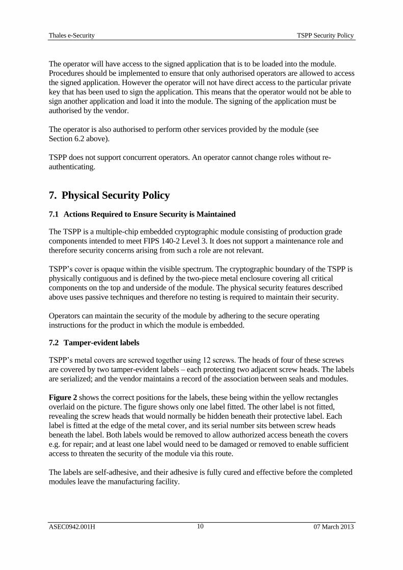
Figure 2 shows the correct positions for the labels, these being within the yellow rectangles
overlaid on the picture. The figure shows only one label fitted. The other label is not fitted,
revealing the screw heads that would normally be hidden beneath their protective label. Each
label is fitted at the edge of the metal cover, and its serial number sits between screw heads
beneath the label. Both labels would be removed to allow authorized access beneath the covers
e.g. for repair; and at least one label would need to be damaged or removed to enable sufficient
access to threaten the security of the module via this route.
The labels are self-adhesive, and their adhesive is fully cured and effective before the completed
modules leave the manufacturing facility.
Thales e-Security TSPP Security Policy
ASEC0942.001H 07 March 2013
11
Figure 2: Label positioning
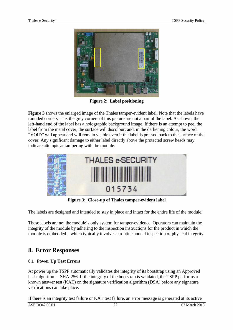
Figure 3 shows the enlarged image of the Thales tamper-evident label. Note that the labels have
rounded corners – i.e. the grey corners of this picture are not a part of the label. As shown, the
left-hand end of the label has a holographic background image. If there is an attempt to peel the
label from the metal cover, the surface will discolour; and, in the darkening colour, the word
“VOID” will appear and will remain visible even if the label is pressed back to the surface of the
cover. Any significant damage to either label directly above the protected screw heads may
indicate attempts at tampering with the module.
Figure 3: Close-up of Thales tamper-evident label
The labels are designed and intended to stay in place and intact for the entire life of the module.
These labels are not the module’s only system for tamper-evidence. Operators can maintain the
integrity of the module by adhering to the inspection instructions for the product in which the
module is embedded – which typically involves a routine annual inspection of physical integrity.
8. Error Responses
8.1 Power Up Test Errors
At power up the TSPP automatically validates the integrity of its bootstrap using an Approved
hash algorithm – SHA-256. If the integrity of the bootstrap is validated, the TSPP performs a
known answer test (KAT) on the signature verification algorithm (DSA) before any signature
verifications can take place.
If there is an integrity test failure or KAT test failure, an error message is generated at its active
Thales e-Security TSPP Security Policy
ASEC0942.001H 07 March 2013
12
serial interface to flag this status and the module then reboots itself.
8.2 Conditional Test Errors
When a signed application is sent to the module, the signature on the application is checked
using the signature verification algorithm (DSA). If the signature verification fails then the
application is not copied to the module’s non-volatile flash memory; and the TSPP outputs an
error message to indicate that the signature verification was unsuccessful, and the unverified
application is erased from its temporary storage in volatile memory.
9. Mitigation of Other Attacks Policy
9.1 Intrusion, Movement, Temperature and Voltage
The module contains a tamper-detection and response system. The tamper-response can be
triggered by a variety of sources.
The physical security provided by the TSPP operates primarily as a protection mechanism for its
battery-backed RAM. If a signed application is loaded by the module, then this RAM is typically
used to contain and protect that application’s critical security parameters. The tamper-response
protects the contents of the RAM by quickly erasing them. The module also contains non-
volatile flash memory. The contents of the flash are not erased when the response is triggered,
and consequently no sensitive information is stored in flash in plaintext.
The intrusion detection system includes serpentine tracks that help to protect against attacks
from drilling. The tamper-response is triggered by any break in the serpentine tracks. Opening
TSPP’s metal covers will also produce this tamper-response. This system also includes
additional facilities for other sources, external to TSPP, to trigger the erasure of the contents of
the battery-backed RAM and thus secure the module by deleting its non-volatile sensitive
plaintext data.
The tamper-detection and response system is powered from the main power supply when this is
available; but while the module is not powered this way, the system it is powered by its battery.
The battery is mounted outside of TSPP and is not part of the module. If the battery is
disconnected or fails, the tamper-response is triggered.
The TSPP has a sensor that can detect movement. Whilst the TSPP’s motion detector is enabled,
any significant tilting or movement of the module is liable to trigger its tamper-response.
The TSPP incorporates environmental failure protection features enabling the module to monitor
and respond to fluctuations in the operating temperature and voltage. Whilst enabled, if the
internal temperature of the module moves outside a predetermined range this will trigger the
tamper-response. The sensing of the precise internal temperature of the module is affected by a
number of factors, but the intention is that the module will operate normally when its ambient
temperature is within the predetermined range. The ambient temperature of the module will be
affected by the enclosure in which it is embedded, and hence the ambient temperature in which
that enclosure itself currently resides.
If the +3.3V supply within the TSPP surges or is actively driven above a threshold voltage level
Thales e-Security TSPP Security Policy
ASEC0942.001H 07 March 2013
13
then the tamper-response is triggered. If the voltage from the main power supply drops below
the normal level at any time then the module shuts down.
NOTE: If the environmental condition that triggers the tamper-response is temporary then the
unit will reset itself following the return to the normal environmental condition. For example if
the tamper-response is triggered by a rise in temperature then the unit will reset itself after the
temperature falls. This should allow the module to function normally again; but it cannot restore
the former contents of the battery-backed RAM that were erased when the tamper-response was
triggered.
Both the motion detector and the temperature sensor can be either turned on, or turned off and
ignored as a potential trigger for the tamper-response. Other sources for triggering the tamper-
response (e.g. the intrusion detection system) are permanently enabled.
The vendor has successfully tested the TSPP’s security features related to intrusion, movement,
temperature and voltage; but these features are not required by the FIPS 140-2 Level 3
validation.
When the module has been loaded with an application it will be necessary to ensure that it is
subject to appropriate protection against unauthorised use. However such protection measures
would form part of the security policy for the loaded application rather than the module itself
and are therefore outside the scope of this validation.
The module also features hardware integrity and functional checks that also trigger the tamper-
response when a failure is detected. These fail-safe design features are also intended to provide
mitigation for attacks designed to selectively disable the module’s tamper-detection and
response system.
9.2 Fault Induction Attacks
Fault induction attacks make use of fluctuations in external forces to cause processing errors
within a module.
The module provides protection against certain types of fault induction attack. The module
contains a temperature sensor and a mechanism to detect abnormal voltage variations.
Users would typically employ a loaded application to enable or disable the module’s
temperature sensor’s ability to initiate the tamper-response; but it must be enabled in order to
provide constant protection against a fault induction attack utilizing temperature extremes.
The temperature sensor (if enabled) and the abnormal voltage detection mechanism will not
require any further action on the part of the user or crypto-officer. If either of these sources
triggers a tamper-response then the module will automatically protect the contents of the battery-
backed RAM by quickly erasing them.
There are no conditions under which the temperature (if enabled) and abnormal voltage
detection mechanisms are known to be ineffective.