tss portable handheld measurement instrument for turbidity
TRANSCRIPT

DOC023.53.90050
TSS Portable handheld measurement instrument for turbidity/solids
User Manual
01/2018, Edition 6

2
3
Table of Contents
Section 1 Specifications ....................................................................................................................... 5
Section 2 General Information.............................................................................................................. 7
2.1 Safety information.............................................................................................................................. 7
2.1.1 Hazard notices in this manual................................................................................................... 7
2.1.2 Precautionary labels ................................................................................................................. 7
2.2 Overview of product........................................................................................................................... 8
2.3 Measurement instrument ................................................................................................................... 8
2.4 Measuring principle............................................................................................................................ 8
2.5 Probe ................................................................................................................................................. 8
Section 3 Installation ............................................................................................................................. 9
3.1 Product contents................................................................................................................................ 9
3.2 Powered via rechargeable batteries ................................................................................................ 10
3.2.1 Inserting the rechargeable batteries ....................................................................................... 10
3.2.2 Install the charger ................................................................................................................... 11
3.2.3 Charging the rechargeable batteries....................................................................................... 12
3.3 Connecting the probe ...................................................................................................................... 13
3.4 Switching the instrument on and off................................................................................................. 14
3.4.1 Register a new probe.............................................................................................................. 14
Section 4 Start Up ................................................................................................................................ 15
4.1 System start overview...................................................................................................................... 15
4.2 User interface and navigation .......................................................................................................... 15
4.2.1 Keypad.................................................................................................................................... 15
4.2.2 Display .................................................................................................................................... 16
4.2.2.1 Querying internal information......................................................................................... 17
4.3 Select language ............................................................................................................................... 17
4.4 Setting the date and time................................................................................................................. 17
4.5 Setting the display ........................................................................................................................... 18
4.6 Setting the units ............................................................................................................................... 18
4.6.1 Sludge blanket level................................................................................................................ 18
4.7 Calibration........................................................................................................................................ 19
4.8 Defining the measurement points .................................................................................................... 19
4.8.1 Overview of calibration curves ................................................................................................ 19
4.8.2 Measurements ........................................................................................................................ 19
4.8.2.1 Practical example for solids measurement .................................................................... 19
4.8.2.2 Practical example for turbidity measurement................................................................. 21
4.9 Setting the integration time .............................................................................................................. 21

4
Section 5 Operation .............................................................................................................................23
5.1 Calibration ........................................................................................................................................23
5.1.1 Important notes for calibration.................................................................................................23
5.1.2 Calibrating ...............................................................................................................................24
5.1.3 Manual calibration value correction.........................................................................................26
5.1.4 Delete calibration point............................................................................................................26
5.1.5 Reset to default calibration......................................................................................................26
5.2 Measure ...........................................................................................................................................26
5.2.1 Selecting the calibration curve ................................................................................................27
5.2.2 Start the measurement............................................................................................................27
5.2.3 Interrupt and resume the measurement ..................................................................................27
5.2.4 Stop measurement ..................................................................................................................27
5.3 Show the data in the display ............................................................................................................27
5.4 Delete data for a calibration curve....................................................................................................27
5.5 Delete stored data for all calibration curves .....................................................................................28
Section 6 Maintenance.........................................................................................................................29
Section 7 Troubleshooting .................................................................................................................31
7.1 Error messages................................................................................................................................31
7.2 Informative messages ......................................................................................................................31
Section 8 Replacement parts and accessories ................................................................................33
8.1 Replacement Parts...........................................................................................................................33

5
Section 1 Specifications
These are subject to change without notice.
Performance specifications
Wavelength 860 nm
Parameter Turbidity Solids (dry matter)
Measurement method
Combined multiple-beam alternating light technique with IR diode system and beam focus
2-channel 90° scattered light measurement in accordance with DIN EN 27027 / ISO 7027; additional measurement value verification through six-channel multiple-angle measurement
Modified absorption measurement Six-channel multiple-angle measurement
Measuring range 0.001–9999 FNU (NTU)0.001–400 g/L (upper limit depends on matrix)
Resolution
0.001 at 0–0.999 FNU 0.01 at 1–9.99 FNU 0.1 at 10–99.9 FNU 1 at >100 FNU
0.001 at 0–0.999 g/L 0.01 at 1–9.99 g/L 0.1 at 10–99.9 g/L 1 at >100 g/L
Precision
Measuring range: 0.001–9999 FNU Accuracy of the measurement value: < 3% or +/- 0.02 FNU (whichever is greater)
Measuring range: 0.001–400 g/L Accuracy of the measurement value: < 4% or +/- 0.001 g/L (whichever is greater)
Reproducibility <4% of measurement value <5% of measurement value
Units FNU, NTU, EBC ppm, mg/L, g/L, %
Calibration 1 calibration curve (factory calibration) 4 calibration curves
Sample temperature 0–60 °C (32–140 °F), up to 80 °C (176 °F) briefly
Pressure range Max. 10 bar
Display LCD, alphanumeric, 4 rows of 16 characters
Input 6 membrane keys, menu with quick access to important functions
Power supply (rechargeable batteries)
6 rechargeable NiMH batteries, type AA HR6 (recommended: 1.2 V/min. 1800 mAH)1
Power consumption Approx. 60 mA
Data log Up to 290 measurement values
Interface RS 485
Probe material Stainless steel, sapphire
Cable 10 m (33 ft), PUR, ∅ 8.3 mm (0.33 in.); S-2000 connector, 6-pin
Protection classProbe: IP68
Control unit: IP 55
SizeProbe: ∅ 40 mm (1.57 in.), length = 29 cm (11.42 in.)
Control unit: 11 x 23 x 4 cm (4.33 x 9 x 1.57 in.)
WeightProbe: 1600 g (3.53 lb)
Control unit: 560 g (1.23 lb)
Warranty 2 years
1 The battery charger must agree with local and national safety regulations and may not be part of the shipment.
6
Specifications
7
Section 2 General Information
2.1 Safety informationPlease read this entire manual carefully before unpacking, setting up, or operating this equipment. Pay attention to all danger and caution notices. Failure to do so could result in serious injury to the operator or damage to the equipment.
To prevent damage to or impairment of the device's protection equipment, the device may only be used or installed as described in this manual.
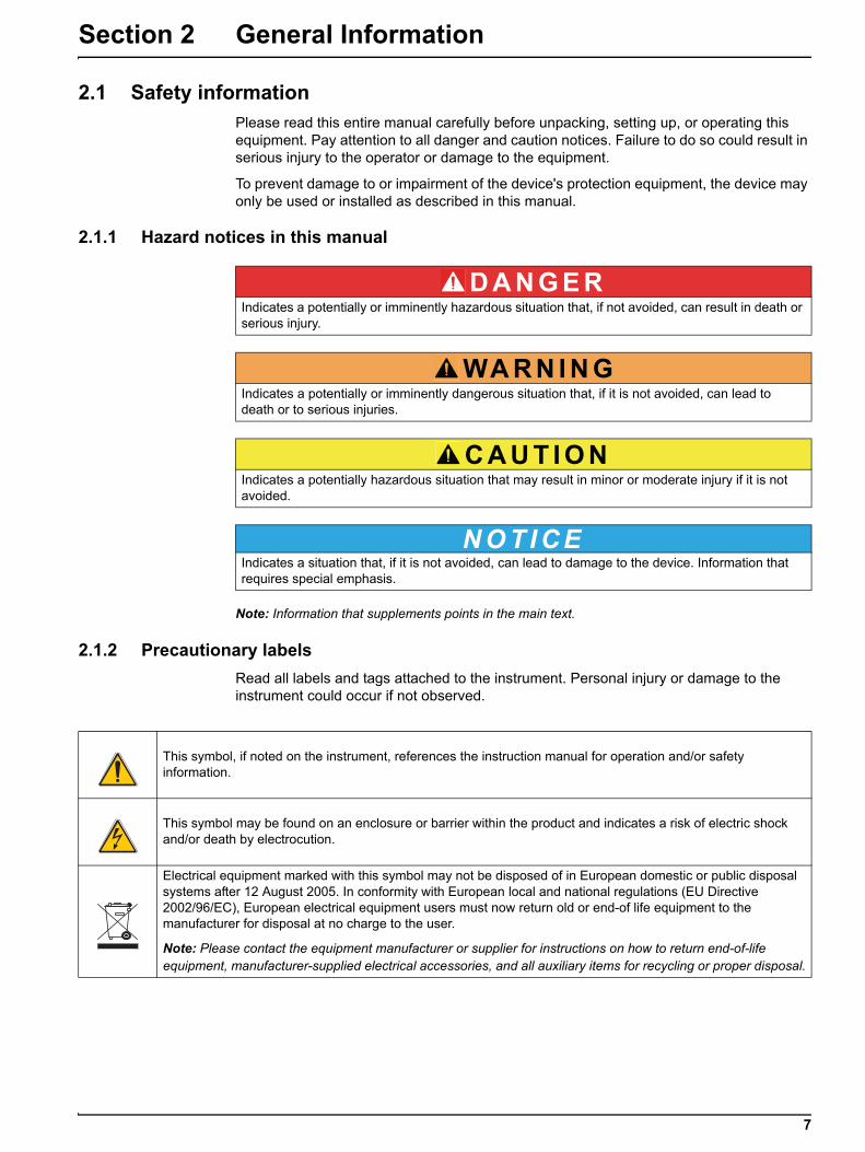
2.1.1 Hazard notices in this manual
Note: Information that supplements points in the main text.
2.1.2 Precautionary labels
Read all labels and tags attached to the instrument. Personal injury or damage to the instrument could occur if not observed.
D A N G E RIndicates a potentially or imminently hazardous situation that, if not avoided, can result in death or serious injury.
WA R N I N GIndicates a potentially or imminently dangerous situation that, if it is not avoided, can lead to death or to serious injuries.
C A U T I O NIndicates a potentially hazardous situation that may result in minor or moderate injury if it is not avoided.
N O T I C EIndicates a situation that, if it is not avoided, can lead to damage to the device. Information that requires special emphasis.
This symbol, if noted on the instrument, references the instruction manual for operation and/or safety information.
This symbol may be found on an enclosure or barrier within the product and indicates a risk of electric shock and/or death by electrocution.
Electrical equipment marked with this symbol may not be disposed of in European domestic or public disposal systems after 12 August 2005. In conformity with European local and national regulations (EU Directive 2002/96/EC), European electrical equipment users must now return old or end-of life equipment to the manufacturer for disposal at no charge to the user.
Note: Please contact the equipment manufacturer or supplier for instructions on how to return end-of-life equipment, manufacturer-supplied electrical accessories, and all auxiliary items for recycling or proper disposal.
8
General Information
2.2 Overview of productThe TSS Portable is a handheld measurement instrument for the analytical determination of turbidity and solids in aqueous media.
2.3 Measurement instrumentThe instrument stores the recorded data under the corresponding calibration curve. Four calibration curves for solids (C-DS1, C-DS2, C-DS3, C-DS4) and one calibration curve for turbidity (C-TU) are available for selection.
For solids measurements, a specific calibration must be assigned to each measurement point (section 5.1, page 23).
All measurement values are saved with details of the selected calibration curve, the measurement value, the homogeneity, the date and the time.
Various individual parameters for input, signal processing and output can be set in the menu (Section 4, page 15).
2.4 Measuring principleThe measuring principle is based on a combined infrared absorption stray light process, which determines the lowest turbidity value according to DIN EN 27027 just as precisely and continuously as the high sludge content. In so doing, the light scattered sideways by the turbidity particles is measured at an angle of 90°. In the case of solid material, the measurement occurs at an angle of 90° and 120°.
2.5 ProbeThe probe contains sensitive optical and electronic components. Care must therefore be taken to ensure that it is not subjected to any hard mechanical impacts. The inside of the probe, and of the display unit, does not contain any components that can be serviced by the user.
9
Section 3 Installation
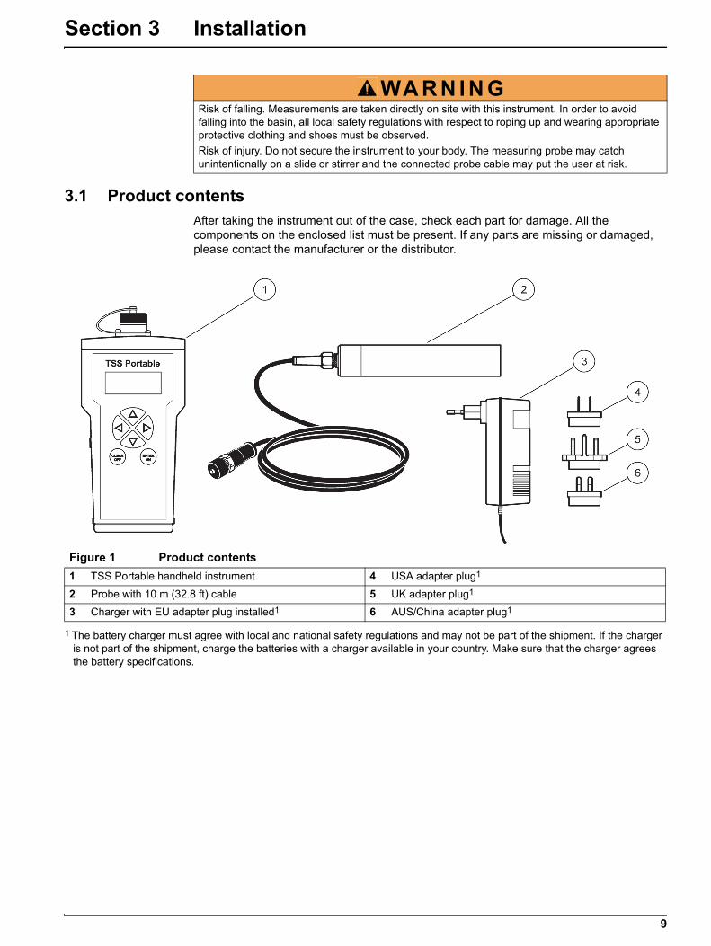
3.1 Product contentsAfter taking the instrument out of the case, check each part for damage. All the components on the enclosed list must be present. If any parts are missing or damaged, please contact the manufacturer or the distributor.
WA R N I N GRisk of falling. Measurements are taken directly on site with this instrument. In order to avoid falling into the basin, all local safety regulations with respect to roping up and wearing appropriate protective clothing and shoes must be observed.
Risk of injury. Do not secure the instrument to your body. The measuring probe may catch unintentionally on a slide or stirrer and the connected probe cable may put the user at risk.
Figure 1 Product contents
1 TSS Portable handheld instrument 4 USA adapter plug1
2 Probe with 10 m (32.8 ft) cable 5 UK adapter plug1
3 Charger with EU adapter plug installed1 6 AUS/China adapter plug1
1 The battery charger must agree with local and national safety regulations and may not be part of the shipment. If the charger is not part of the shipment, charge the batteries with a charger available in your country. Make sure that the charger agrees the battery specifications.

10
Installation
3.2 Powered via rechargeable batteries
The instrument is operated by six rechargeable NiMH batteries (Figure 2).
3.2.1 Inserting the rechargeable batteries
1. Press in both catches at the same time and release the cover.
2. Take the battery holder out of the battery compartment (Figure 2).
3. Insert the delivered six rechargeable NiMH batteries into the battery holder. Take note of the markings for the polarity.
Note: Make sure that the rechargeable batteries have been inserted into the battery compartment correctly.
4. Connect the battery holder to the battery clip.
5. Push the battery holder into the battery compartment.
6. Push the cover onto the battery compartment until it audibly engages in the catches.
WA R N I N GRisk of fire and explosion. Only use rechargeable NiMH batteries and ensure that the rechargeable NiMH batteries are inserted correctly in the battery compartment. Incorrect insertion of the rechargeable NiMH batteries may damage the instrument or lead to fire or explosions.
WA R N I N GRisk of fire and explosion. When using not rechargeable AA batteries, the not rechargeable batteries could explode if the instrument is connected to the charger. Only use rechargeable NiMH batteries from the manufacturer of the instrument.
N O T I C ERemove the rechargeable NiMH batteries if the instrument is not to be used for a period of time.
Only use rechargeable NiMH batteries from the manufacturer of the instrument.

11
Installation
3.2.2 Install the charger1
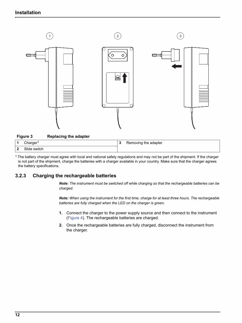
1. Push the slide switch (item 2, Figure 3) on the back of the charger up and remove the adapter (item 3, Figure 3).
2. Fix the required adapter to the charger, until it audibly locks into place.
3. Insert the charging plug (item 3, Figure 4) into the charging socket (item 4, Figure 4) of the instrument.
4. Connect the power (100–240 V~/50–60 Hz).
Figure 2 Inserting the rechargeable batteries
1 Catch 4 Battery holder
2 Battery compartment 5 rechargeable Batteries
3 Battery clip 6 Cap
1 The battery charger must agree with local and national safety regulations and may not be part of the shipment. If the charger is not part of the shipment, charge the batteries with a charger available in your country. Make sure that the charger agrees the battery specifications.
WA R N I N GRisk of fire and explosion.
Only use the battery charger to charge the rechargeable NiMH batteries, while batteries inside the instrument.
12
Installation
3.2.3 Charging the rechargeable batteries
Note: The instrument must be switched off while charging so that the rechargeable batteries can be charged.
Note: When using the instrument for the first time, charge for at least three hours. The rechargeable batteries are fully charged when the LED on the charger is green.
1. Connect the charger to the power supply source and then connect to the instrument (Figure 4). The rechargeable batteries are charged.
2. Once the rechargeable batteries are fully charged, disconnect the instrument from the charger.
Figure 3 Replacing the adapter
1 Charger1 3 Removing the adapter
2 Slide switch
1 The battery charger must agree with local and national safety regulations and may not be part of the shipment. If the charger is not part of the shipment, charge the batteries with a charger available in your country. Make sure that the charger agrees the battery specifications.

13
Installation
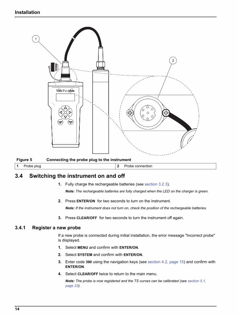
3.3 Connecting the probeRemove the protective cap and connect the probe plug to the instrument (Figure 5).
Figure 4 Charging the rechargeable batteries
1 Charger1 4 Charging socket
2 Discharge button (yellow) 5 LED lamp (green => rechargeable batteries fully charged)
3 Charging plug 6 LED lamp (red => rechargeable batteries currently charging)
1 The battery charger must agree with local and national safety regulations and may not be part of the shipment. If the charger is not part of the shipment, charge the batteries with a charger available in your country. Make sure that the charger agrees the battery specifications.
14
Installation
3.4 Switching the instrument on and off1. Fully charge the rechargeable batteries (see section 3.2.3).
Note: The rechargeable batteries are fully charged when the LED on the charger is green.
2. Press ENTER/ON for two seconds to turn on the instrument.
Note: If the instrument does not turn on, check the position of the rechargeable batteries.
3. Press CLEAR/OFF for two seconds to turn the instrument off again.
3.4.1 Register a new probe
If a new probe is connected during initial installation, the error message "Incorrect probe" is displayed.
1. Select MENU and confirm with ENTER/ON.
2. Select SYSTEM and confirm with ENTER/ON.
3. Enter code 390 using the navigation keys (see section 4.2, page 15) and confirm with ENTER/ON.
4. Select CLEAR/OFF twice to return to the main menu.
Note: The probe is now registered and the TS curves can be calibrated (see section 5.1, page 23).
Figure 5 Connecting the probe plug to the instrument
1 Probe plug 2 Probe connection
15
Section 4 Start Up
4.1 System start overview1. Switch on the measurement instrument (section 3.4, page 14).
2. Connect the probe to the measurement instrument (section 3.3, page 13).
3. Edit the time/date, display, units, language and integration time (section 4.3, page 17).
4. Calibration of the solids calibration curve in line with calibration instructions (section 4.7, page 19).
5. Select desired calibration curve (section 4.8, page 19).
6. Show the data in the display (section 5.3, page 27).
4.2 User interface and navigation
4.2.1 Keypad
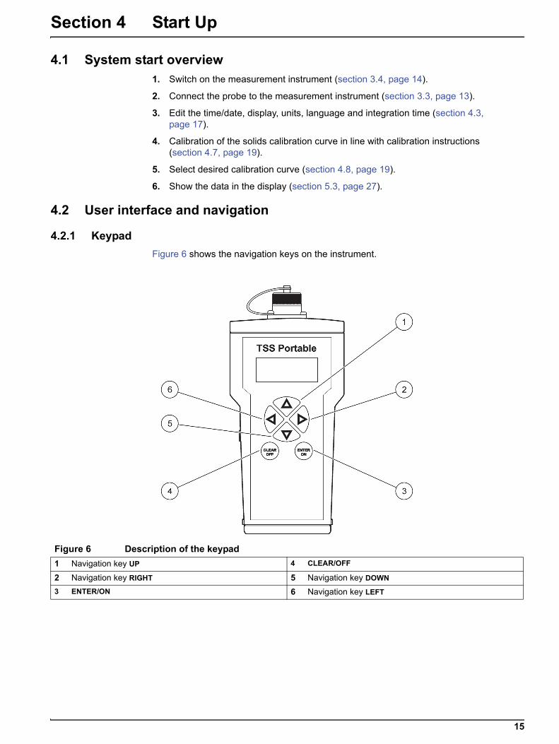
Figure 6 shows the navigation keys on the instrument.
Figure 6 Description of the keypad
1 Navigation key UP 4 CLEAR/OFF
2 Navigation key RIGHT 5 Navigation key DOWN
3 ENTER/ON 6 Navigation key LEFT

16
Start Up
4.2.2 Display
In its basic setting, the display shows the main measurement variables and the date/time (Figure 7). It can be set in a user-defined manner, see section 4.5, page 18.
Table 1 Navigating in the menu
Navigation key Description
Navigation key RIGHT/LEFT Navigation occurs with the RIGHT/LEFT navigation keys.
Navigation key UP/DOWN Navigation occurs with the UP/DOWN navigation keys.
ENTER/ON– Confirm selection and entry with ENTER/ON.
– Switch the instrument on with ENTER/ON.
CLEAR/OFF
– Abort actions with CLEAR/OFF.
– Press CLEAR/OFF to return to the previous menu option or abort entries.
– Switch the instrument off with CLEAR/OFF.
Vertical arrowsThe vertical arrows in the display show that there are additional menu options or measurement values above or below.
Cursor– The cursor points to the selected main menu option. Navigation occurs with the RIGHT/LEFT navigation keys.
– The active decimal place is displayed.
> (arrow) The current selection is displayed
Figure 7 Display of results from the instrument with connected probe
1 Cursor 4 Current decimal place
2 Vertical arrows 5 Menu option
3 Input mode 6 Active selection
17
Start Up
4.2.2.1 Querying internal information
Information about the probe and instrument can be queried directly from the main menu using the navigation keys UP/DOWN.
The following information is displayed:
a. Measurement value (homogeneity in %)
b. Battery charge level
c. Diagnosis parameters, such as:
• Probe serial number (instrument information)
• Probe software version (instrument information)
• Probe number Start XX (probe diagnosis data)
• DATA rem. cap. XXX (Remaining capacity of the measurement points)
• Fault no. XX
• Serial no. XXXXX (instrument designation)
• Software version XXXXX (instrument designation)
4.3 Select languageThe instrument supports the languages German and English. The instrument functions in the selected language until the option is changed.
1. Select MENU, confirm with ENTER/ON.
2. Select SPRACHE/LANGUAGE and confirm with ENTER/ON.
3. Select DEUT./GERMAN. for German or ENGL./ENGLISH for English and confirm with ENTER/ON.
4. Press CLEAR/OFF to return to the main menu.
4.4 Setting the date and timeSet the time and date display:
1. Select MENU, confirm with ENTER/ON.
2. Select TIME/DATE, confirm with ENTER/ON.
3. Select YEAR, MONTH, DAY, HOUR, MINUTE or SECOND, confirm with ENTER/ON.
4. Change the displayed values with the navigation keys.
5. Confirm each setting with ENTER/ON.
6. Press CLEAR/OFF to return to the MENU.
Note: Press CLEAR/OFF again to return to the main menu.
18
Start Up
4.5 Setting the displayIt is possible to custom-define the first two rows of the display. In the standard setting, the first line shows the main measured variable and the second line shows the date/time.
1. Select MENU, confirm with ENTER/ON.
2. Select DISPLAY, confirm with ENTER/ON.
3. Select ROW 1, confirm with ENTER/ON.
4. Select option for ROW 1, confirm with ENTER/ON.
• Measurement value
• Homogeneous
• Battery
• Time
5. Select ROW 2, confirm with ENTER/ON.
6. Select option for ROW 2, confirm with ENTER/ON.
7. Press CLEAR/OFF to return to the MENU.
Note: Press CLEAR/OFF again to return to the main menu.
4.6 Setting the unitsThe following measurement units are available for turbidity and solids:
Turbidity units (TU): FNU, NTU, EBC
Solids units (DS1 to DS4): ppm, mg/L, g/L, %
1. Select MENU, confirm with ENTER/ON.
2. Select UNITS, confirm with ENTER/ON.
3. Select the desired calibration curve (C-TU, C-DS1, C-DS2, C-DS3 or C-DS4) and confirm withENTER/ON.
4. Select the desired measurement unit and confirm with ENTER/ON.
5. Press CLEAR/OFF to return to the MENU.
Note: Press CLEAR/OFF again to return to the main menu.
4.6.1 Sludge blanket level
To determine the sludge blanket level, set the units to mg/L, g/L or %. Select an integration time of 0 seconds (refer to section 4.9, page 21) to increase the response time. Calibrate the measurement system and slowly lower the sensor into the clarifier. Once the sludge blanket level is reached, the solids concentration will increase significantly. The distance of the sludge blanket from the surface of the water can then be read off from the meter markings on the probe cable.
19
Start Up
4.7 CalibrationFor turbidity measurement, a standard curve C-TU is already stored in the probe. Calibration is not required.
However, for solids measurement, calibration is required in order to set the rough measurement signals to a calibrated display (refer to section 5.1, page 23). A precise solids measurement is not possible without calibration. There are four calibration curves available: C-DS1, C-DS2, C-DS3, C-DS4. These curves can be allocated to the individual measurement points.
4.8 Defining the measurement points
4.8.1 Overview of calibration curves
• C-TU = Turbidity curve (standard curve)
• C-DS1 = solids curve 1 (calibration curve)
• C-DS2 = solids curve 2 (calibration curve)
• C-DS3 = solids curve 3 (calibration curve)
• C-DS4 = solids curve 4 (calibration curve)
4.8.2 Measurements
4.8.2.1 Practical example for solids measurement
Note: The type and composition of the solid particles of a medium can differ greatly. For this reason, it is not possible to define a general standard, and different measurement media must be calibrated specifically in each case.
For the solids measurement, calibration is required. There are four curves available: C-DS1, C-DS2, C-DS3, C-DS4. Each curve can be assigned to any measurement point. In the example, curve C-DS1 is selected.
1. Connect the probe to the instrument.
2. To switch on the instrument, press ENTER/ON for 2 seconds.
Select calibration curve
3. Select MENU, confirm with ENTER/ON.
4. Select CALIBRATE, confirm with ENTER/ON.
5. Select CURVE C-TU and confirm withENTER/ON.
Note: Curve C-TU is the default setting.
6. Select calibration curve C-DS1 with the navigation keys UP/DOWN and confirm withENTER/ON.
The instrument reads the probe data and info text appears on the display.

20
Start Up
Calibrate curve C-DS1:
7. Select MEMORY and confirm with ENTER/ON.
8. Lower the probe into a container that contains a homogeneous sample.
9. Select POINT 1 and confirm with ENTER/ON while stirring the measuring medium with the probe.
The distance between the probe head and the walls and base of the container must always be more than 70 mm (2.76 in.). It takes 5 to 20 seconds to record the calibration point; then the selection menu for calibration appears. While recording, the display shows the note "Memory".
10. Take the probe out of the container and clean it.
11. Determine the solids content of the sample in the laboratory.
12. Select *POINT 1 and confirm withENTER/ON.
13. Enter the laboratory value with the navigation keys and confirm with ENTER/ON.
• Navigation key LEFT/RIGHT: Jump to next/previous decimal place
• Navigation key UP/DOWN: Change number
The laboratory value is saved. The main menu is shown.
Measure:
14. Select MEASURE, confirm with ENTER/ON.
15. Select START and confirm with ENTER/ON.
Note: Data is automatically saved every minute, max. 290 measurement points.
Stop measurement:
16. Select MEASURE, confirm with ENTER/ON.
17. Select STOP, confirm with ENTER/ON.
Delete the saved measurement points:
18. Select DATA, confirm with ENTER/ON.
19. Select DELETE MEP and confirm withENTER/ON.
20. Select YES and confirm withENTER/ON.

21
Start Up
4.8.2.2 Practical example for turbidity measurement
A standard curve C-TU is stored for the turbidity measurement.
1. Connect probe to instrument.
2. To switch the instrument on, press ENTER/ON for 2 seconds.
3. Select READ and confirm withENTER/ON.
4. Place probe in measuring medium.
5. Select START and confirm with ENTER/ON.
Note: The data is automatically saved every minute, max. 290 measurement points.
6. To stop the measurement, select READ and confirm with ENTER/ON.
7. Select STOP, confirm with ENTER/ON.
Delete the saved measurement points:
8. Select DATA and confirm with ENTER/ON.
9. Select DELETE MEP and confirm withENTER/ON.
10. Select YES and confirm with ENTER/ON.
4.9 Setting the integration timeNote: The measurement values are averaged out over the integration time, which results in a smooth measurement signal. For the sludge blanket level measurement (refer to section 4.6.1, page 18), select the integration time 0 seconds.
Upon delivery, the default value is set to 30 seconds. The integration time can be set to between 0 and 1000 seconds.
1. Select MENU and confirm with ENTER/ON.
2. Select EXTRAS and confirm with ENTER/ON.
3. Select INTEGRATION and confirm withENTER/ON.
4. Change the displayed value with the navigation keys.
5. Confirm each entry with ENTER/ON.
6. Press CLEAR/OFF to return to the MENU.
Note: Press CLEAR/OFF again to return to the main menu.
22
Start Up
23
Section 5 Operation
5.1 CalibrationTurbidity measurements do not need to be calibrated, as a standardized calibration curve according to ISO 7027 is stored in the instrument. It is possible to create a customer-specific calibration of the turbidity curve. If the standard curve has been altered, a star (*) appears before the measurement point.
Solids measurements must be calibrated on site. It is not possible to define a general standard for this as the type and composition of the solid particles can differ greatly.
5.1.1 Important notes for calibration
Calibration containers In order to avoid reflections of the measurement beam on the base and walls of the container, a black—or at the very least dark-colored—container should be used for calibration.
The probe can also remain in the tank so long as a representative laboratory sample can be taken at this point.
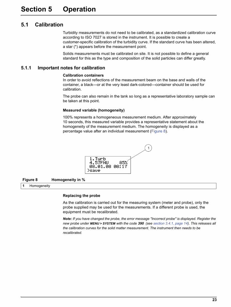
Measured variable (homogeneity)
100% represents a homogeneous measurement medium. After approximately 10 seconds, this measured variable provides a representative statement about the homogeneity of the measurement medium. The homogeneity is displayed as a percentage value after an individual measurement (Figure 8).
Replacing the probe
As the calibration is carried out for the measuring system (meter and probe), only the probe supplied may be used for the measurements. If a different probe is used, the equipment must be recalibrated.
Note: If you have changed the probe, the error message "Incorrect probe" is displayed. Register the new probe under MENU > SYSTEM with the code 390 (see section 3.4.1, page 14). This releases all the calibration curves for the solid matter measurement. The instrument then needs to be recalibrated.
Figure 8 Homogeneity in %
1 Homogeneity
24
Operation
5.1.2 Calibrating
The instrument can save one turbidity curve and up to four solids calibration curves. This makes measurements in media with different qualities possible. Each measurement point can have one of the saved calibration curves assigned to it individually.
1-point calibration
In order to define a calibration curve, it is generally sufficient to use a single calibration point in the probe's measuring range. This should lie in the upper third of the expected measuring range.
Note: If the measurement value is below or above the range defined by a point, the instrument displays an error message: Calibration insufficient +/-. This means an additional calibration point is required.
Multiple-point calibration
For broad measuring ranges, a second calibration point must be recorded:
• First calibration point (lower value) at as low a concentration as possible.
• Second calibration point (upper value) at as high a concentration as possible.
Up to three calibration points per curve can be recorded. To record several calibration points, the sample is diluted or sedimented. Recorded calibration points are indicated by a star (e.g. *point 1) and remain saved even if the device is switched off in the meantime.
1. Fill a black container with a representative sample of the measuring medium. Ensure that it is mixed evenly.
2. Use a part of the sample for the solids analysis in the laboratory.
3. Clean the probe.
4. Dip the probe into the container.
5. Select MENU, confirm with ENTER/ON.
6. Select CALIBRATE, confirm with ENTER/ON.
The instrument reads the probe data and info text appears on the display.
7. Select the curve shown and confirm with ENTER/ON.
8. Select the desired curve and confirm with ENTER/ON.
9. Select MEMORY and confirm with ENTER/ON.
10. Select POINT… (Point 1, 2 or 3), confirm with ENTER/ON. In doing so, stir the measuring medium with the probe.
The distance between the probe head and the walls and base of the container must always be more than 70 mm (2.76 in.) (Figure 9). It takes 5 to 20 seconds to record the calibration point; then the selection menu for calibration appears. While recording, "Memory" is indicated on the display.
11. Take the probe out of the container and clean it. If necessary, record more calibration points with diluted or settled samples. Remove part of these samples for the solids analysis in the laboratory.
12. Determine the solids content of the sample(s) in the laboratory.
13. Select *POINT… (*Point 1, 2 or 3) and confirm with ENTER/ON.

25
Operation
14. Enter the laboratory values using the navigation keys and confirm with ENTER/ON.
• Navigation key LEFT/RIGHT: Jump to the next/previous decimal place
• Navigation key UP/DOWN: Change number
The laboratory value is saved. The main menu is shown.
Repeat steps 1 to 14 to record additional calibration points.
The instrument automatically sorts the saved calibration points according to the size of the calibration values. The sequence in which the calibration points were recorded is not considered. Point 1 is always allocated the lowest calibration value. Point 2 is allocated the next larger calibration value. Point 3 is allocated the largest calibration value.
The value determined in the laboratory can be corrected at any time by overwriting (refer to section 5.1.3).
Figure 9 Minimum distances of the probe head in the container
1 Probe 2 Container

26
Operation
5.1.3 Manual calibration value correction
1. Select MENU, confirm with ENTER/ON.
2. Select CALIBRATE, confirm with ENTER/ON.
The instrument reads the probe data.
3. Select the curve shown and confirm with ENTER/ON.
4. Select the desired curve and confirm withENTER/ON.
5. Select the desired point and confirm with ENTER/ON.
6. Overwrite the existing calibration point.
7. Enter the value for the calibration point using the navigation keys and confirm with ENTER/ON.
• Navigation key LEFT/RIGHT: Jump to next/previous decimal place
• Navigation key UP/DOWN: Change number
5.1.4 Delete calibration point
Same procedure as in section 5.1.3. Set the concentration of the calibration point to the value 0.000 and confirm withENTER/ON. The calibration point is deleted.
5.1.5 Reset to default calibration
If the turbidity calibration was changed, it can be reset to the default calibration in accordance with ISO 7027.
Note: Stop the current measurement before the default calibration is reset.
1. Select MENU, confirm with ENTER/ON.
2. Select CALIBRATE, confirm with ENTER/ON.
The instrument reads the probe data.
3. Select turbidity curve C-Tu and confirm with ENTER/ON.
Note: If turbidity curve C-Tu is not shown in the menu, select the curve shown and confirm with ENTER/ON. The selection menu for the curves is shown. Select curve C-Tu and confirm with ENTER/ON. Curve C-TU is activated. Open the selection menu for curve C-TU with ENTER/ON, select RESET and confirm with ENTER/ON.
4. Press navigation key UP/DOWN , select RESET and confirm with ENTER/ON.
The DS curves can also be reset to the default calibration (1-point calibration at 4 g/L). However, a precise determination of the solids concentration can only be obtained through calibration (refer to section 5.1, page 23).
5.2 MeasureNote: In order to obtain precise solids measurement results, you must calibrate the instrument before the first measurement is taken. Without any calibration of the DS curves, the instrument returns to 1-point default calibration at 4 g/L. Deviations from the actual measurement value may occur.

27
Operation
5.2.1 Selecting the calibration curve
Before starting the measurement, the calibration curve that corresponds to the measurement point must be selected.
1. Select MENU, confirm with ENTER/ON.
2. Select CALIBRATE, confirm with ENTER/ON.
3. Selectthe curve shown and confirm with ENTER/ON.
4. Select the desired curve with the navigation key UP/DOWN and confirm with ENTER/ON.
5. Select CLEAR/OFF twice to return to the main menu.
5.2.2 Start the measurement
When starting the measurement, the measurement is carried out continuously and the current measurement value is saved at intervals.
1. Select MEASURE, confirm with ENTER/ON.
2. Select START and confirm with ENTER/ON.
5.2.3 Interrupt and resume the measurement
1. Press CLEAR/OFF for 2 seconds.
The instrument is switched off and the measurement is interrupted.
2. Press ENTER/ON for 2 seconds.
The instrument switches on and the measurement continues with the same settings as before the instrument was switched off.
5.2.4 Stop measurement
1. Select MEASURE, confirm with ENTER/ON.
2. Select STOP, confirm with ENTER/ON.
5.3 Show the data in the displayThe display shows the stored data for the corresponding calibration curves.
1. Select the desired calibration curve (refer to section 5.2.1, page 27).
2. Select DATA, confirm with ENTER/ON.
3. Select DISPLAY DATA and confirm with ENTER/ON.
Only the stored data for the selected calibration curve is displayed.
5.4 Delete data for a calibration curve1. Select the desired calibration curve (refer to section 5.2.1, page 27).
2. Select DATA, confirm with ENTER/ON.
3. Select DELETE MEP and confirm with ENTER/ON.
Only the stored data for the selected calibration curve is deleted.
4. Select YES, confirm with ENTER/ON.
Note: NO aborts the erasing procedure.

28
Operation
5.5 Delete stored data for all calibration curves1. Select MENU, confirm with ENTER/ON.
2. Select SYSTEM, confirm with ENTER/ON.
3. Enter the value 379 using the navigation keys and confirm with ENTER/ON.

29
Section 6 Maintenance
The cleanliness of the measurement windows in the sensor head is critical to the accuracy of the measurement results!
Cleaning the instrument
Clean the instrument with a damp, lint-free cloth.
Cleaning the measurement windows
The windows are made of sapphire glass. If required, they can be cleaned with any conventional cleaning agent and a soft cloth. In the case of very stubborn deposits, clean with a soft cloth soaked in 5% hydrochloric acid.
Observe the safety conditions and wear protective clothing!
• Safety glasses
• Gloves
• Overalls
C A U T I O NPotential chemical and biological eye and skin hazards.
Only qualified personnel should perform the tasks described in this section of the operating manual.
30
Maintenance
31
Section 7 Troubleshooting
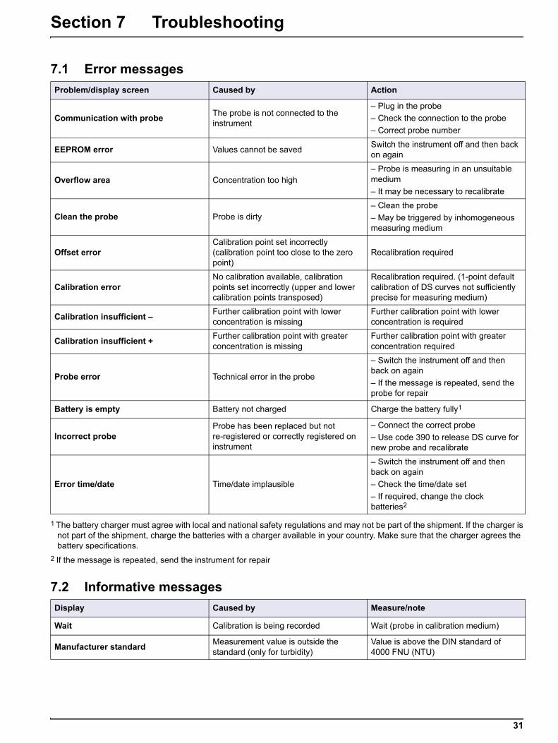
7.1 Error messages
Problem/display screen Caused by Action
Communication with probeThe probe is not connected to the instrument
– Plug in the probe
– Check the connection to the probe
– Correct probe number
EEPROM error Values cannot be savedSwitch the instrument off and then back on again
Overflow area Concentration too high– Probe is measuring in an unsuitable medium
– It may be necessary to recalibrate
Clean the probe Probe is dirty– Clean the probe
– May be triggered by inhomogeneous measuring medium
Offset errorCalibration point set incorrectly (calibration point too close to the zero point)
Recalibration required
Calibration errorNo calibration available, calibration points set incorrectly (upper and lower calibration points transposed)
Recalibration required. (1-point default calibration of DS curves not sufficiently precise for measuring medium)
Calibration insufficient –Further calibration point with lower concentration is missing
Further calibration point with lower concentration is required
Calibration insufficient +Further calibration point with greater concentration is missing
Further calibration point with greater concentration required
Probe error Technical error in the probe
– Switch the instrument off and then back on again
– If the message is repeated, send the probe for repair
Battery is empty Battery not charged Charge the battery fully1
Incorrect probeProbe has been replaced but not re-registered or correctly registered on instrument
– Connect the correct probe
– Use code 390 to release DS curve for new probe and recalibrate
Error time/date Time/date implausible
– Switch the instrument off and then back on again
– Check the time/date set
– If required, change the clock batteries2
1 The battery charger must agree with local and national safety regulations and may not be part of the shipment. If the charger is not part of the shipment, charge the batteries with a charger available in your country. Make sure that the charger agrees the battery specifications.
2 If the message is repeated, send the instrument for repair
7.2 Informative messages
Display Caused by Measure/note
Wait Calibration is being recorded Wait (probe in calibration medium)
Manufacturer standardMeasurement value is outside the standard (only for turbidity)
Value is above the DIN standard of 4000 FNU (NTU)

32
Troubleshooting
33
Section 8 Replacement parts and accessories
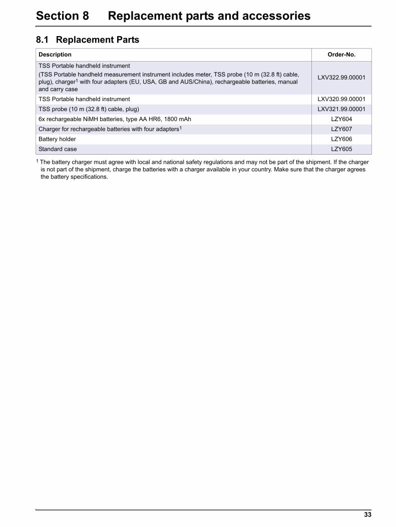
8.1 Replacement Parts
Description Order-No.
TSS Portable handheld instrument
(TSS Portable handheld measurement instrument includes meter, TSS probe (10 m (32.8 ft) cable, plug), charger1 with four adapters (EU, USA, GB and AUS/China), rechargeable batteries, manual and carry case
LXV322.99.00001
TSS Portable handheld instrument LXV320.99.00001
TSS probe (10 m (32.8 ft) cable, plug) LXV321.99.00001
6x rechargeable NiMH batteries, type AA HR6, 1800 mAh LZY604
Charger for rechargeable batteries with four adapters1
1 The battery charger must agree with local and national safety regulations and may not be part of the shipment. If the charger is not part of the shipment, charge the batteries with a charger available in your country. Make sure that the charger agrees the battery specifications.
LZY607
Battery holder LZY606
Standard case LZY605
34
Replacement parts and accessories


HACH COMPANY World HeadquartersP.O. Box 389, Loveland, CO 80539-0389 U.S.A.Tel. (970) 669-3050(800) 227-4224 (U.S.A. only)Fax (970) [email protected]
HACH LANGE GMBHWillstätterstraße 11D-40549 Düsseldorf, GermanyTel. +49 (0) 2 11 52 88-320Fax +49 (0) 2 11 52 [email protected]
HACH LANGE Sàrl6, route de Compois1222 VésenazSWITZERLANDTel. +41 22 594 6400Fax +41 22 594 6499
© Hach Company/Hach Lange GmbH, 2004–2008, 2012, 2017-2018. All rights reserved. Printed in Germany 01/2018, Edition 6