tsu baki o f canada l imite d w e lde d ste e l chain and ...tsubaki.ca/pdfs/tsubaki_wsc.pdf · w e...
TRANSCRIPT
Tsubaki of Canada LimitedWelded Steel Chain
and Sprockets
Welded Steel
2
Welded Steel Chain from Tsubaki is manufactured by welding side bars to separately formed barrels (bushings) and pins. Welds fuseeach end portion of each barrel to an adjacent side bar end portion to create high fatigue resistance. Welds also fuse each end portionof each through hardened pin to an adjacent side bar end portion for maximum strength. Special design considerations includeenlarged shoulders for tight press fit in the sidebars and tapered construction for rapid assembly. Tsubaki’s oversized rivet headoutlasts conventional rivet heads. The result is a welded steel chain that is designed and made to offer strength, precision, impactand wear resistance. This results in a chain that is built to withstand both punishing shock load and abrasive conditions. And eachcomponent is engineered to tight tolerances. This kind of chain is found throughout the world in lumber mills, pulp and paper millsand other industries where severe applications demand strength and reliability.
3
Welded Steel
D B L E
T P P
R
P P
H
Offset Sidebar Welded Steel Chains
Notes:1. WR: Offset sidebar style, with heat treated rivets.2. WH: Offset sidebar series, with all parts heat treated.3. WRXHD: Offset sidebar extra heavy duty series, with
heat-treated rivets.
Extra Heavy Duty Offset Sidebar Welded Steel Chains
4. WHXHD: Offset sidebar extra heavy duty series, with all parts heat-treated.5. If extended wear life pin is required Tsubaki can supply
IBR as an option for all chains on this page.
All dimensions in inches unless otherwise stated.
All dimensions in inches unless otherwise stated.
Side Bars Chain Width
Chain NumberPitch
PThickness
THeight
H
Pin Dia.
DOverall
L
Length of
Bearing E B
Barrel Dia.
R
Ultimate Strength
(lbs.)
Maximum Allowable
Load (lbs.)
Approx. Weight (lbs./ft.)
WR-78 2.609 0.250 1.251.251.25
0.50 3.00 2.00 1.00 0.84 30,000 4,500 4.2WH-78 2.609 0.250 0.50 3.00 2.00 1.00 0.84 33,000 5,500 4.2WR-78-4 4.000 0.250 0.50 3.00 2.00 1.00 0.84 25,600 4,500 3.5WR-82 3.075 0.250 1.25 0.56 3.24 2.25 1.13 1.00 30,000 5,000 5.0WH-82 3.075 0.250 1.25 0.56 3.24 2.25 1.13 1.00 36,000 6,000 5.0* WR-124IBR 4.000 0.382 1.50 0.75 4.25 2.75 1.50 1.25 50,000 8,200 8.0WH-124 4.000 0.382 1.50 0.75 4.25 2.75 1.50 1.25 57,000 9,500 8.0WR-111 4.760 0.382 1.75 0.75 4.80 3.39 2.25 1.25 50,400 9,500 9.2WH-111 4.760 0.382 1.75 0.75 4.80 3.39 2.25 1.25 60,000 12,000 9.2WR-106 6.000 0.382 1.50 0.75 4.25 2.75 1.50 1.25 50,000 8,200 6.6WH-106 6.000 0.382 1.50 0.75 4.25 2.75 1.50 1.25 60,000 12,000 6.6WR-110 6.000 0.382 1.50 0.75 4.81 3.00 1.50 1.25 46,000 6,800 6.6WH-110 6.000 0.382 1.50 0.75 4.81 3.00 1.75 1.25 60,000 12,000 6.6WR-132 6.050 0.500 2.00 1.00 6.14 4.37 1.75 1.75 85,500 14,100 14.2WH-132 6.050 0.500 2.00 1.00 6.14 4.37 3.00 1.75 122,000 20,300 14.2WR-150 6.050 0.500 2.50 1.00 6.50 4.37 3.00 1.75 100,000 19,000 17.1WH-150 6.050 0.500 2.50 1.00 6.50 4.37 2.75 1.75 148,000 20,300 17.1WR-155 6.050 0.563
0.5632.50 1.13 6.41 4.63 2.75 1.75 148,000 22,000 19.8
WH-155 6.050 2.50 1.13 6.41 4.63 2.75 1.75 175,000 29,000 19.8WR-157 6.050 0.625 2.50 1.13 6.75 4.63 2.75 1.75 148,000 22,000 20.1WH-157 6.050 0.625 2.50 1.13 6.75 4.63 2.75 1.75 175,000 29,000 20.1WR-159 6.125 0.625 3.00 1.25 6.75 4.63 185,000 28,000 26.0WH-159 6.125 0.625 3.00 1.25 6.75 4.63 210,000 32,000 26.0WR-200 6.125 0.625 2.50 1.25 6.75 4.63 185,000 28,000 22.1WH-200 6.125 0.625 2.50 1.25 6.75 4.63 190,000
1.901.901.901.90
2.752.752.752.75 32,000 22.1
EffectiveDistanceBetween
Welds
Side Bars Chain Width
Chain NumberPitch
PThickness
THeight
H
Pin Dia.
DOverall
L
Length of
Bearing E B
Ultimate Strength
(lbs.)
Maximum Allowable
Load (lbs.)
Approx. Weight (lbs./ft.)
WR-78XHD 2.636 0.38 1.25 0.56 3.37 2.00 1.00 1.00 30,000 5,000 6.2WH-78XHD 2.636 0.38 1.25 0.56 3.37 2.00 1.00 1.00 36,000 6,000 6.2WR-82XHD 3.075 0.38 1.50 0.75 3.75 2.38 1.13 1.25 50,400 8,400 8.5WH-82XHD 3.075 0.38 1.50 0.75 3.75 2.38 1.13 1.25 57,000 9,500 8.5WR-124XHD 4.063 0.50 2.00 1.00 4.87 3.00 1.50 1.63
1.6385,500 14,200 14.8
WH-124XHD 4.063 0.50 2.00 1.00 4.87 3.00 1.50 122,000 20,400 14.8WR-106XHD 6.050 0.50 2.00 1.00 4.87 3.00 1.50 1.75 85,000 14,200 12.2WH-106XHD 6.050 0.50 2.00 1.00 4.87 3.00 1.50 1.75 122,000 20,400 12.2WR-132XHD 6.050 0.63 2.00 1.00 6.75 4.67 3.00 1.75 120,000 20,000 16.5WH-132XHD 6.050 0.63 2.00 1.00 6.75 4.67 3.00 1.75 122,000 20,400 16.5
Barrel Dia.
EffectiveDistanceBetween
WeldsR
* WR124IBR is produced standard with extended wear life pin.

Welded Steel
4
Notes:1. WRC: Straight sidebar style, with heat treated rivets.2. WHC: Straight sidebar series, with all parts heat treated.3. WRCXHD: Straight sidebar extra heavy duty series, with heat-treated rivets.4. WHCXHD: Straight sidebar extra heavy duty series, with all parts heat-treated.
P P
DB LE
T
R H
Extra Heavy Duty Straight Sidebar Welded Steel Chains
Side Bars Chain Width
Chain NumberPitch
PThickness
THeight
H
Pin Dia.
DOverall
L
Lengthof
Bearing E B R
Ultimate Strength
(lbs.)
Maximum Allowable
Load (lbs.)
Approx. Weight (lbs./ft.)
WRC-78 2.609 0.25 1.25 0.50 3.00 2.00 1.00 0.84 27,000 4,500 4.3WRC-131 3.075 0.38 1.50 0.75 3.56 2.00 0.88 1.25 50,400 8,400 8.4WHC-131 3.075 0.38 1.50 0.75 3.56 2.00 0.88 1.25 57,000 8,400 8.4WRC-124 4.000 0.38 1.50 0.75 4.25 2.75 1.50 1.25 50,400 8,400 7.8WRC-111 4.051 0.38 1.75 0.75 4.81 3.38 1.75 1.25 50,400 8,400 8.0WRC-110 6.000 0.38 1.50 0.75 4.25 2.75 1.50 1.25 50,400 8,400 7.2WRC-132 6.050 0.50 2.00 1.00 6.50 4.41 2.75 1.75 85,500 14,100 14.1WRC-150 6.050 0.50 2.50 1.00 6.50 4.41 2.75 1.75 120,000 19,000 16.3
Barrel Dia.
EffectiveDistanceBetween
Welds
Side Bars Chain Width
Chain NumberPitch
PThickness
THeight
H
Pin Dia.
DOverall
LBearing
E B R
Ultimate Strength
(lbs.)
Maximum Allowable
Load (lbs.)
Approx. Weight (lbs./ft.)
WRC-82XHD 3.075 0.38 1.50 0.75 3.75 2.40 1.13 1.25 50,400 8,400 8.5WRC-124XHD 4.063 0.50 2.00 1.00 4.88 3.00 1.50 1.63 85,000 14,200 14.6WRC-110XHD 6.050 0.50 2.00 1.00 4.88 3.00 1.50 1.63 85,000 14,200 11.8WRC-132XHD 6.050 0.63 2.00 1.00 6.75 4.66 3.13 1.63 120,000 20,000 15.3
Lengthof Barrel
Dia.
EffectiveDistanceBetween
Welds
Straight Sidebar Welded Steel ChainsAll dimensions in inches unless otherwise stated.
All dimensions in inches unless otherwise stated.
5
Welded Steel
O
J
NN
CX X XX
T
S
C CC
O
K
T
S
J2
All dimensions in inches unless otherwise stated.
C1C1
T
C2
CCK1 K1
E1
E2
K2 K2
Q R
O
All dimensions in inches unless otherwise stated.
K-1 Attachment K-2 Attachment
F-4 Attachment
Chain Number C J J2 K N O S T XWR-78 2.00 1.25 0.81 2.13 1.25 0.38 0.88 0.25 0.50WR-78XHD 2.00 1.25 0.81 2.13 1.25 0.38 0.88 0.25 0.50WR-82 2.38 1.50 0.50 2.25 1.75 0.38 0.88 0.25 0.63WR-82XHD 2.38 1.50 0.50 2.25 1.75 0.38 1.13 0.38 0.63WR-124 2.63 2.00 0.88 3.00 1.75 0.38 1.13 0.38 0.63WR-124XHD 2.63 2.00 0.88 4.00 1.75 0.50 1.50 0.50 0.75WR-111 3.18 2.18 1.00 4.00 1.75 0.38 1.25 0.38 0.63WR-132 3.75 3.00 1.63 4.25 2.00 0.50 1.50 0.50 0.88WR-132XHD 3.75 3.00 1.63 4.25 2.00 0.50 1.50 0.50 0.88WR-150 3.75 - 1.63 4.25 - 0.50 1.75 0.50 0.50
Chain Number C2 E2 T K1 K2 C E1 Q R C1 O
Approx. Weight (lbs./ft.)
WR-78 1.75 1.00 0.25 0.50 0.88 2.25 0.94 0.63 1.18 1.88 0.38 8.3WR-78XHD 1.75 1.00 0.25 0.50 0.88 2.25 0.94 0.63 1.18 1.88 0.38 9.9WR-82 1.81 1.25 0.25 0.44 0.88 2.50 1.13 0.81 1.19 2.06 0.38 8.9WR-82XHD 2.06 1.25 0.38 0.50 1.06 2.50 1.13 1.06 1.19 2.06 0.38 12.5WR-124 2.06 1.16 0.38 0.50 1.06 2.63 1.06 1.06 1.31 2.06 0.38 11.6
Welded Steel
6
G
T
H
L
A
Pitch
Pitch
LE
VA
RT
OT N
OIT
CE
RID
All dimensions in inches unless otherwise stated.
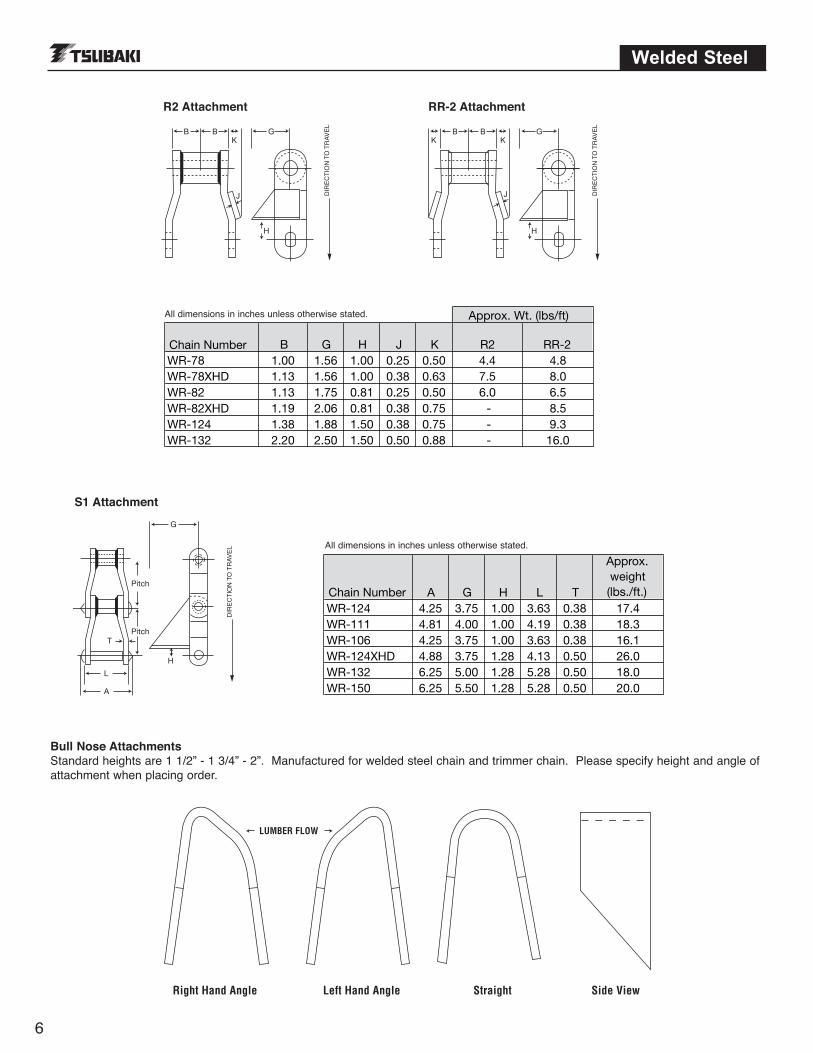
S1 Attachment
LE
VA
RT
OT N
OIT
CE
R ID
LE
VA
RT
OT N
OIT
CE
RID
B B B B
HH
J J
G GK K K
R2 Attachment RR-2 Attachment
LUMBER FLOW
Right Hand Angle Left Hand Angle Straight Side View
Bull Nose AttachmentsStandard heights are 1 1/2” - 1 3/4” - 2”. Manufactured for welded steel chain and trimmer chain. Please specify height and angle ofattachment when placing order.
Approx. Wt. (lbs/ft)
Chain Number B G H J K R2 RR-2WR-78 1.00 1.56 1.00 0.25 0.50 4.4 4.8WR-78XHD 1.13 1.56 1.00 0.38 0.63 7.5 8.0WR-82 1.13 1.75 0.81 0.25 0.50 6.0 6.5WR-82XHD 1.19 2.06 0.81 0.38 0.75 - 8.5WR-124 1.38 1.88 1.50 0.38 0.75 - 9.3WR-132 2.20 2.50 1.50 0.50 0.88 - 16.0
All dimensions in inches unless otherwise stated.
Chain Number A G H L T
Approx. weight (lbs./ft.)
WR-124 4.25 3.75 1.00 3.63 0.38 17.4WR-111 4.81 4.00 1.00 4.19 0.38 18.3WR-106 4.25 3.75 1.00 3.63 0.38 16.1WR-124XHD 4.88 3.75 1.28 4.13 0.50 26.0WR-132 6.25 5.00 1.28 5.28 0.50 18.0WR-150 6.25 5.50 1.28 5.28 0.50 20.0

7
Welded Steel
D B A
O
E
C
K
G
H K H
J
Pitch
G
J
All dimensions in inches unless otherwise stated.
All dimensions in inches unless otherwise stated.
RF2 Attachment RF12 Attachment
A22 Attachment
Chain Number A B C D E OWR-78 2.00 0.63 1.25 0.25 1.25 0.44WR-124 3.00 0.88 1.75 0.38 2.00 0.56WR-111 3.50 0.88 1.75 0.38 2.38 0.56WR-106 2.75 0.88 1.75 0.38 3.00 0.56WR-132 4.25 1.00 1.75 0.50 3.00 0.81WR-132XHD 4.25 1.00 2.00 0.63 3.00 0.81
Chain Number G H J K
Approx. weight (lbs./ft.)
WR-78 2.69 1.50 0.25 3.00 7.7WR-78XHD 2.69 1.50 0.38 3.00 10.7WR-82XHD 2.75 2.14 0.38 3.25 12.3WR-124 3.25 2.00 0.50 4.25 15.8WR-111 3.25 2.13 0.50 7.75 14.5WR-132 3.50 3.00 0.75 9.00 28.5
Specify left or right hand when ordering.
Specify both K and G dimensions when ordering.
Welded Steel
8
PITCH
Z
X
Y
Style A
PITCHX
YY
Style B
PITCH
Z
X
Y
Style C
Z
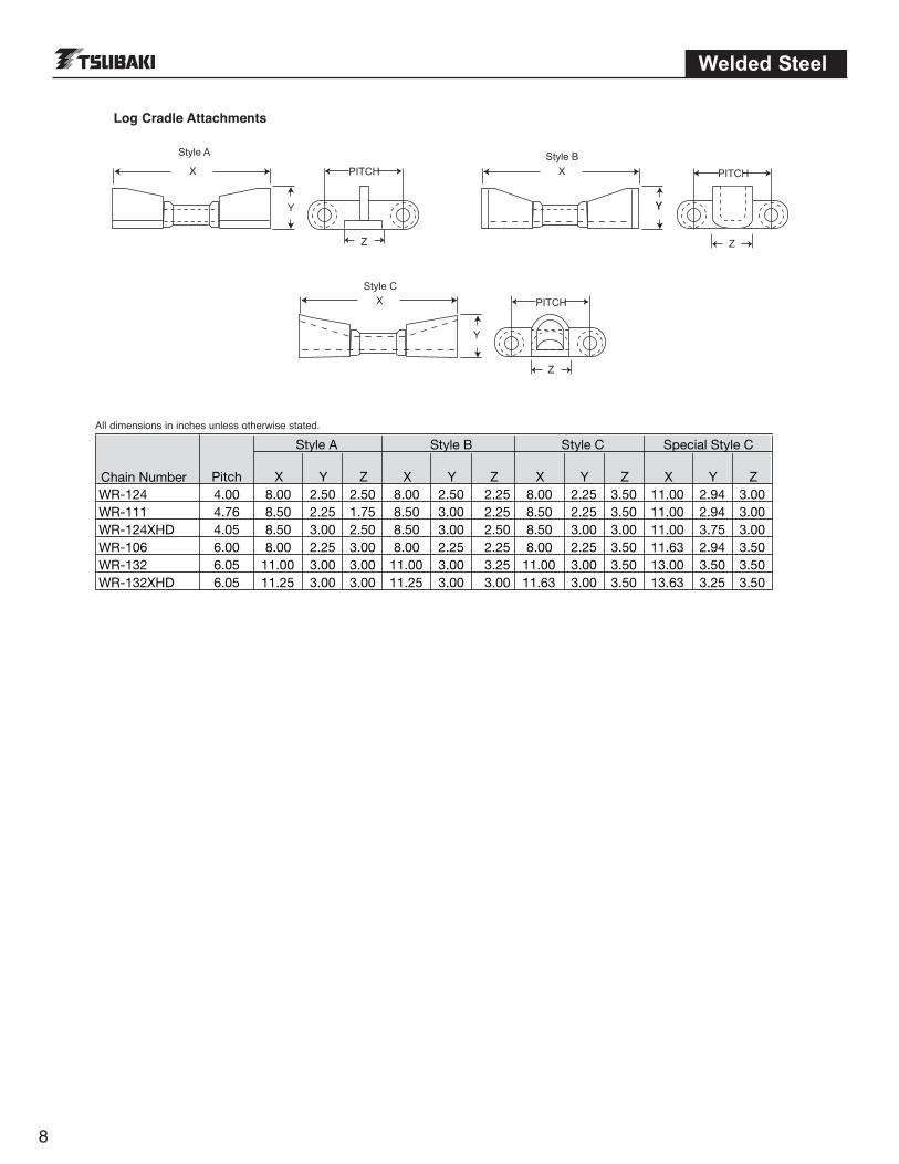
Log Cradle Attachments
All dimensions in inches unless otherwise stated.
Style A Style B Style C Special Style C
Chain Number Pitch X Y Z X Y Z X Y Z X Y ZWR-124 4.00 8.00 2.50 2.50 8.00 2.50 2.25 8.00 2.25 3.50 11.00 2.94 3.00WR-111 4.76 8.50 2.25 1.75 8.50 3.00 2.25 8.50 2.25 3.50 11.00 2.94 3.00WR-124XHD 4.05 8.50 3.00 2.50 8.50 3.00 2.50 8.50 3.00 3.00 11.00 3.75 3.00WR-106 6.00 8.00 2.25 3.00 8.00 2.25 2.25 8.00 2.25 3.50 11.63 2.94 3.50WR-132 6.05 11.00 3.00 3.00 11.00 3.00 3.25 11.00 3.00 3.50 13.00 3.50 3.50WR-132XHD 6.05 11.25 3.00 3.00 11.25 3.00 3.00 11.63 3.00 3.50 13.63 3.25 3.50
9
Drag Chains
L B E
T
H
PP
D
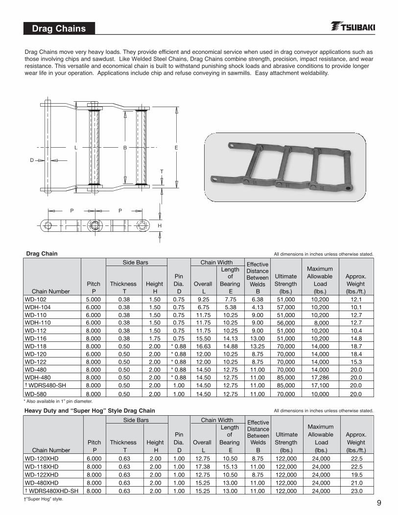
Drag Chains move very heavy loads. They provide efficient and economical service when used in drag conveyor applications such asthose involving chips and sawdust. Like Welded Steel Chains, Drag Chains combine strength, precision, impact resistance, and wearresistance. This versatile and economical chain is built to withstand punishing shock loads and abrasive conditions to provide longerwear life in your operation. Applications include chip and refuse conveying in sawmills. Easy attachment weldability.
Side Bars Chain Width
Chain NumberPitch
PThickness
THeight
H
Pin Dia.
DOverall
L
Length of
Bearing E B
Ultimate Strength
(lbs.)
Maximum Allowable
Load (lbs.)
Approx. Weight (lbs./ft.)
WD-102 5.000 0.38 1.50 0.75 9.25 7.75 6.38 51,000 10,200 12.1WDH-104 6.000 0.38 1.50 0.75 6.75 5.38 4.13 57,000 10,200 10.1WD-110 6.000 0.38 1.50 0.75 11.75 10.25 9.00 51,000 10,200 12.7WDH-110 6.000 0.38 1.50 0.75 11.75 10.25 9.00 56,000 8,000 12.7WD-112 8.000 0.38 1.50 0.75 11.75 10.25 9.00 51,000 10,200 10.4WD-116 8.000 0.38 1.75 0.75 15.50 14.13 13.00 51,000 10,200 14.8WD-118 8.000 0.50 2.00 * 0.88 16.63 14.88 13.25 70,000 14,000 18.7WD-120 6.000 0.50 2.00 * 0.88 12.00 10.25 8.75 70,000 14,000 18.4WD-122 8.000 0.50 2.00 * 0.88 12.00 10.25 8.75 70,000 14,000 15.3WD-480 8.000 0.50 2.00 * 0.88 14.50 12.75 11.00 70,000 14,000 20.0WDH-480 8.000 0.50 2.00 * 0.88 14.50 12.75 11.00 85,000 17,286 20.0† WDRS480-SH 8.000 0.50 2.00 1.00 14.50 12.75 11.00 85,000 17,100 20.0
Side Bars Chain Width
Chain NumberPitch
PThickness
THeight
H
Pin Dia.
DOverall
L
Length of
Bearing E B
Ultimate Strength
(lbs.)
Maximum Allowable
Load (lbs.)
Approx. Weight (lbs./ft.)
WD-120XHD 6.000 0.63 2.00 1.00 12.75 10.50 8.75 122,000 24,000 22.5WD-118XHD 8.000 0.63 2.00 1.00 17.38 15.13 11.00 122,000 24,000 22.5WD-122XHD 8.000 0.63 2.00 1.00 12.75 10.50 8.75 122,000 24,000 19.5WD-480XHD 8.000 0.63 2.00 1.00 15.25 13.00 11.00 122,000 24,000 21.0† WDRS480XHD-SH 8.000 0.63 2.00 1.00 15.25 13.00 11.00 122,000 24,000 23.0
EffectiveDistanceBetween
Welds
EffectiveDistanceBetween
Welds
WD-580 8.000 0.50 2.00 1.00 14.50 12.75 11.00 70,000 10,000 20.0
Drag Chain
Heavy Duty and “Super Hog” Style Drag Chain
All dimensions in inches unless otherwise stated.
All dimensions in inches unless otherwise stated.
* Also available in 1” pin diameter.
†”Super Hog” style.
Drag Chains
10
M
H
A
J
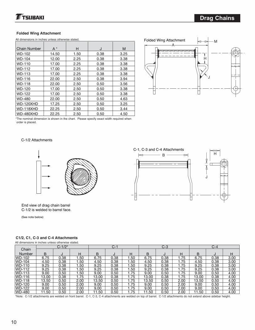
Folded Wing Attachment
Chain Number A * H J MWD-102 14.50 1.50 0.38 3.25WD-104 12.00 2.25 0.38 3.38WD-110 17.00 2.25 0.38 3.38WD-112 17.00 2.25 0.38 3.38WD-113 17.00 2.25 0.38 3.38WD-116 22.00 2.50 0.38 3.94WD-118 22.00 2.50 0.50 3.56WD-120 17.00 2.50 0.50 3.38WD-122 17.00 2.50 0.50 3.38WD-480 22.00 2.50 0.50 4.63WD-120XHD 17.25 2.50 0.50 3.25WD-118XHD 22.25 2.50 0.50 3.44WD-480XHD 22.25 2.50 0.50 4.50
Folded Wing Attachment
C-1/2* C-1 C-3 C-4
B J H B J H B J H B J HWD-102 6.75 0.38 1.50 6.75 0.38 1.50 6.75 0.38 1.75 6.75 0.38 3.00WD-104 4.50 0.38 1.50 4.50 0.38 1.50 4.50 0.38 1.75 4.50 0.38 3.00WD-110 9.25 0.38 1.50 9.25 0.38 1.50 9.25 0.38 1.75 9.25 0.38 3.00WD-112 9.25 0.38 1.50 9.25 0.38 1.50 9.25 0.38 1.75 9.25 0.38 3.00WD-113 9.00 0.50 1.50 9.00 0.50 1.75 9.00 0.50 1.75 9.00 0.50 4.00WD-116 13.00 0.38 1.75 13.00 0.38 1.75 13.00 0.38 1.75 13.00 0.38 4.00WD-118 13.50 0.50 2.00 13.50 0.50 1.75 13.50 0.50 2.00 13.50 0.50 4.00WD-120 9.00 0.50 2.00 9.00 0.50 1.75 9.00 0.50 2.00 9.00 0.50 4.00WD-122 9.00 0.50 2.00 9.00 0.50 1.75 9.00 0.50 2.00 9.00 0.50 4.00WD-480 11.50 0.50 2.00 11.50 0.50 1.75 11.50 0.50 2.00 11.50 0.50 4.00
ChainNumber
C-1/2 Attachments
End view of drag chain barrelC-1/2 is welded to barrel face.
(See note below)
C1/2, C1, C-3 and C-4 AttachmentsAll dimensions in inches unless otherwise stated.
All dimensions in inches unless otherwise stated.
H
J
B
C-1, C-3 and C-4 Attachments
*Note: C-1/2 attachments are welded on front barrel. C-1, C-3, C-4 attachments are welded on top of barrel. C-1/2 attachments do not extend above sidebar height.
*The nominal dimension is shown in the chart. Please specify exact width required when order is placed.
11
Sprockets
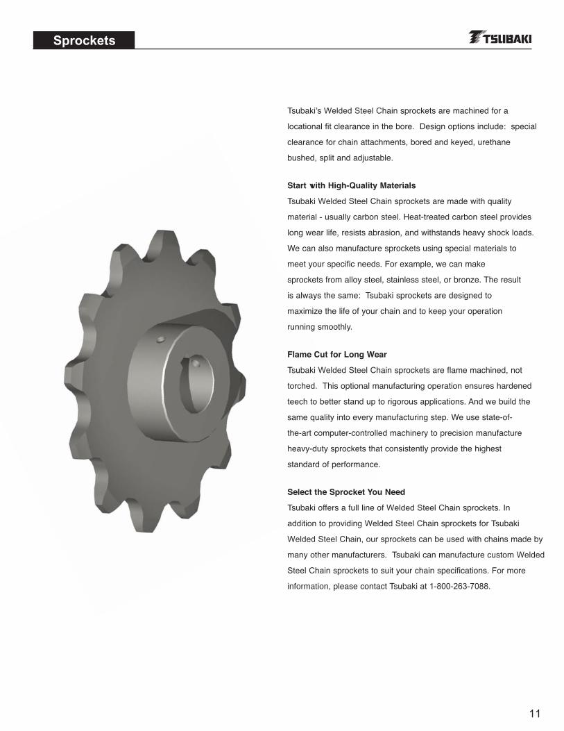
Tsubaki’s Welded Steel Chain sprockets are machined for a
locational fit clearance in the bore. Design options include: special
clearance for chain attachments, bored and keyed, urethane
bushed, split and adjustable.
Start with High-Quality Materials
Tsubaki Welded Steel Chain sprockets are made with quality
material - usually carbon steel. Heat-treated carbon steel provides
long wear life, resists abrasion, and withstands heavy shock loads.
We can also manufacture sprockets using special materials to
meet your specific needs. For example, we can make
sprockets from alloy steel, stainless steel, or bronze. The result
is always the same: Tsubaki sprockets are designed to
maximize the life of your chain and to keep your operation
running smoothly.
Flame Cut for Long Wear
Tsubaki Welded Steel Chain sprockets are flame machined, not
torched. This optional manufacturing operation ensures hardened
teech to better stand up to rigorous applications. And we build the
same quality into every manufacturing step. We use state-of-
the-art computer-controlled machinery to precision manufacture
heavy-duty sprockets that consistently provide the highest
standard of performance.
Select the Sprocket You Need
Tsubaki offers a full line of Welded Steel Chain sprockets. In
addition to providing Welded Steel Chain sprockets for Tsubaki
Welded Steel Chain, our sprockets can be used with chains made by
many other manufacturers. Tsubaki can manufacture custom Welded
Steel Chain sprockets to suit your chain specifications. For more
information, please contact Tsubaki at 1-800-263-7088.