tt-3020b installation manual - telemar manual page 4 30may95 the antenna is shipped in a separate...
TRANSCRIPT

TT-3020BTT-3020B
MaritimeMaritimeCapsat TransceiverCapsat Transceiver
for theInmarsat-C Network
Installation ManualInstallation Manual
Version 2.20
© Copyright Thrane & Thrane A/S. May 1995Tobaksvejen 23, DK-2860 Soeborg. Denmark

Information in this document is subject to change without notice and does not representa commitment on the part of Thrane & Thrane A/S.
© 1995 Thrane & Thrane A/S. All right reserved. Printed in Denmark.
Document Number TT-99-102829-220. Release Date: 30MAY95.

Safety SummarySafety SummaryThe following general safety precautions must be observed
during all phases of operation, service and repair of thisequipment. Failure to comply with these precautions or with
specific warnings elsewhere in this manual violates safetystandards of design, manufacture and intended use of the
equipment. Thrane & Thrane A/S assumes no liability for thecustomers failure to comply with these requirements.
GROUND THE EQUIPMENTGROUND THE EQUIPMENTTo minimize shock hazard, the equipment chassis and cabinetmust be connected to an electrical ground. For this purpose
the equipment is equipped with a power connector including aground terminal.
DO NOT OPERATE IN AN EXPLOSIVE ATMOSPHEREDO NOT OPERATE IN AN EXPLOSIVE ATMOSPHEREDo not operate the equipment in the presence of flammable
gases or fumes. Operation of any electrical equipment in suchan environment constitutes a definite safety hazard.
KEEP AWAY FROM LIVE CIRCUITSKEEP AWAY FROM LIVE CIRCUITSOperating personnel must not remove equipment covers.Component replacement and internal adjustment must bemade by qualified maintenance personnel. Do not replacecomponents with the power cable connected. Under certain
conditions, dangerous voltages may exist even with the powercable removed. To avoid injuries, always disconnect power
and discharge circuits before touching them.
DO NOT SERVICE OR ADJUST ALONEDO NOT SERVICE OR ADJUST ALONEDo not attempt internal service or adjustments unless anotherperson, capable of rendering first aid resuscitation, is present.
DO NOT SUBSTITUTE PARTS OR MODIFYDO NOT SUBSTITUTE PARTS OR MODIFYEQUIPMENTEQUIPMENT
Because of the danger of introducing additional hazards, do notsubstitute parts or perform any unauthorized modification to the
equipment.

Thrane & ThraneThrane & ThraneTTTT-3020B-3020B Capsat Transceiver Capsat Transceiver
Installation ManualInstallation Manual
30MAY9530MAY95 Page Page ii
Table of Contents1. Introduction 1
2. Equipment installation 2
2.1 Introduction 22.1.1 Initial inspection 22.1.2 Packing list 32.1.3 Storage 42.1.4 Repacking for shipment 4
2.2 Technical specifications 5
2.3 Power requirements 72.3.1 AC mains operation 7
2.3.1.1 Integrated Capsat System 72.3.1.2 Power connector 8
2.3.2 Fuses 92.3.3 Grounding 9
2.4 TT-3001 Antennas 112.4.1 Antenna types 11
2.4.1.1 TT-3001B Option 001 Maritime Antenna 112.4.2 Mounting bracket 122.4.3 Antenna connector 122.4.4 Antenna cable 122.4.5 Mounting considerations 13
2.4.5.1 TT-3001B-opt. 001 Maritime Antenna 132.4.6 Safety Distance for Antenna Units 15
2.5 TT-3020B Capsat Transceiver 162.5.1 Mounting bracket 162.5.2 Communication port 16
2.5.2.1 Baudrate and protocol settings 162.5.2.2 X4 Connector interface 172.5.2.3 Interfacing to peripherals 17
2.5.2.3.1 TT-3606A Message Terminal 182.5.2.3.2 IBM Compatible PC (Personal Computer) 182.5.2.3.3 Computerized equipment 182.5.2.3.4 Flow control 19
2.5.3 T-Bus Connector 192.5.3.1 Changing port X5 to input NMEA 0183 data 202.5.3.2 Changing port X5 to output NMEA 0183 data 202.5.3.3 Changing port X5 to T-Bus communication 20
2.5.4 Switch settings 212.5.5 Jumper configurations 22
2.5.5.1 Default configuration 222.5.6 Clock battery back-up 222.5.7 NMEA 0183 Navigational Interface 23
2.5.7.1 NMEA 0183 Reception 232.5.7.2 NMEA 0183 Transmission 24

Thrane & ThraneThrane & ThraneTTTT-3020B-3020B Capsat Transceiver Capsat TransceiverInstallation ManualInstallation Manual
Page Page iiii 30MAY9530MAY95
2.6 TT-3606A Message Terminal (optional) 262.6.1 Communication port 262.6.2 Printer port 262.6.3 VDU Interface 27
2.6.3.1 TT-3602D SVGA Monitor 272.6.3.2 TT-3680M DC to DC Converter (70Watt) 28
2.6.4 TT-3601A keyboard 28
2.7 TT-3680A/B Power Supply (optional) 292.7.1 TT-3680A Power Supply (80 Watt) 292.7.2 TT-3680B Power Supply (200 Watt) 29
2.8 TT-3608A Hard Copy Printer 302.8.1 Mounting plate 30
2.9 TT-3042B Remote Alarm 32
2.10 Built-in GPS (optional) 32
2.11 General interconnect information 34
3. System Generation 35
3.1 Introduction 35
3.2 Terminal preparation 363.2.1 TT-3606A Message Terminal 363.2.2 IBM Compatible PC 363.2.3 Computerized equipment/handheld terminals 36
3.3 Entering the System Generation 37
3.4 The system generation menu 373.4.1 Entering your mobile type and number 38
3.4.1.1 Fast access to the Mobile Type 38
3.5 Leaving the system generation 40
4. Commissioning of the equipment 41
4.1 Introduction 41
4.2 The first login (commissioning) 42
4.3 Overview of a Link Test 42
4.4 Details of a Link Test 43
4.5 Commissioned status 44
4.6 Uncommissioned status 44
Thrane & ThraneThrane & ThraneTTTT-3020B-3020B Capsat Transceiver Capsat Transceiver
Installation ManualInstallation Manual
30MAY9530MAY95 Page Page 11
1.1. IntroductionIntroduction
This manual provides instructions for installing, configuring and testing of a TT-3000Integrated Capsat System that includes a model TT-3020B Capsat Transceiver.
The various Capsat Systems available from Thrane & Thrane are decribed in the manualIntegrated Capsat Systems. Please consult this manual if your uncertain what kind ofsystem you will be installing.
A wide variety of options and accessories may be linked together with the CapsatTransceiver, and the specific installation and configuring of these are to be found intheir respective Reference Manuals.
The relevant cabinet drawings and mounting information illustrations are found in theback of this manual.
Thrane & ThraneThrane & ThraneTTTT-3020B-3020B Capsat Transceiver Capsat TransceiverInstallation ManualInstallation Manual
Page Page 22 30MAY9530MAY95
2.2. Equipment installationEquipment installation
2.1 IntroductionThis chapter provides specific information enabling you to install the Model TT-3020BCapsat Transceiver into your own system, with minimal effort. The default, or factoryconfiguration is described, together with procedures for altering this configuration.
2.1.1 Initial inspection
WARNINGWARNINGTo avoid hazardous electrical shock, do not perform electricaltests if there is any sign of shipping damage to any portion of
the front or rear panel or the outer cover. Read the safetysummary at the front of this manual before installing or
operating the TT-3020B Transceiver.
Inspect the shipping carton immediately upon receipt for evidence of mishandlingduring the transit. If the shipping carton is severely damaged or waterstained requestthat the carrier's agent be present when opening the carton. Save the carton packingmaterial for future use.
Contents of the shipment should be as listed in the packing list below. If the contentsare incomplete, if there is mechanical damage or defect, or if the TT-3020B CapsatTransceiver does not work properly, notify your dealer.
After you unpack the TT-3020B Capsat Transceiver , inspect it thoroughly for hiddendamage and loose components or fittings.
² Inspect the cable harness for stress, loose or broken wires, or broken cable tires.
² Examine all the components for loose or missing hardware. Tighten all loosehardware.
² Remove loose debris from the cabinet interior.
Thrane & ThraneThrane & ThraneTTTT-3020B-3020B Capsat Transceiver Capsat Transceiver
Installation ManualInstallation Manual
30MAY9530MAY95 Page Page 33
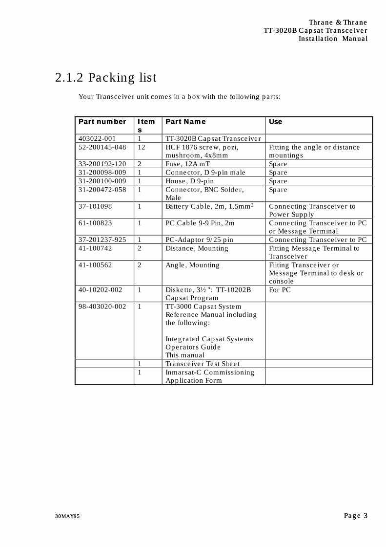
2.1.2 Packing listYour Transceiver unit comes in a box with the following parts:
Part numberPart number ItemItemss
Part NamePart Name UseUse
403022-001 1 TT-3020B Capsat Transceiver52-200145-048 12 HCF 1876 screw, pozi,
mushroom, 4x8mmFitting the angle or distancemountings
33-200192-120 2 Fuse, 12A mT Spare31-200098-009 1 Connector, D 9-pin male Spare31-200100-009 1 House, D 9-pin Spare31-200472-058 1 Connector, BNC Solder,
MaleSpare
37-101098 1 Battery Cable, 2m, 1.5mm2 Connecting Transceiver toPower Supply
61-100823 1 PC Cable 9-9 Pin, 2m Connecting Transceiver to PCor Message Terminal
37-201237-925 1 PC-Adaptor 9/25 pin Connecting Transceiver to PC41-100742 2 Distance, Mounting Fitting Message Terminal to
Transceiver41-100562 2 Angle, Mounting Fiiting Transceiver or
Message Terminal to desk orconsole
40-10202-002 1 Diskette, 3½": TT-10202BCapsat Program
For PC
98-403020-002 1 TT-3000 Capsat SystemReference Manual includingthe following:
Integrated Capsat SystemsOperators GuideThis manual
1 Transceiver Test Sheet1 Inmarsat-C Commissioning
Application Form

Thrane & ThraneThrane & ThraneTTTT-3020B-3020B Capsat Transceiver Capsat TransceiverInstallation ManualInstallation Manual
Page Page 44 30MAY9530MAY95
The Antenna is shipped in a separate box.
69-102881 1 TT-3001B Antenna Unit51-200833-003 1 Unbraco Key, Steel N3 For antenna mounting51-200834-006 1 Unbraco Key, Steel N6 For antenna mounting
1 Self-bonding tape, 30cm For sealing the antennaconnector
1 Description for fitting self-bonding tape
403020-941 1 Antenna cable, 5m
Table 1: Packing list.
2.1.3 StorageThe TT-3020B may be stored or shipped in temperatures within the limits -40° C to +80°C. It is advisable to protect the TT-3020B from extreme temperature variation which cancause excessive condensation. It is recommended that the TT-3020B is unpackedimmediately on delivery.
2.1.4 Repacking for shipmentThe shipping carton for the TT-3020B has been carefully designed to protect thetransceiver and its accessories during shipment. This carton and its associated packingmaterial should be used if repacking for shipment. Attach a tag indicating the type ofservice required, a failure description, return address, model number and full serialnumber. Mark the carton FRAGILE to ensure careful handling.
If the original shipping carton is not available, the following general instructions shouldbe used for repacking with commercially available material.
1. Wrap the TT-3020B in heavy paper or plastic. Attach a tag indicating the type ofservice required, return address, model number and full serial number.
2. Use a strong shipping container, e.g. a double walled carton of 160 kg test material.
3. Protect the front- and rear panel with cardboard and insert a 7 cm to 10 cm layer ofshock absorbing material between all surfaces of the equipment and the sides of thecontainer.
4. Seal the shipping container securely.
5. Mark the shipping container FRAGILE to ensure careful handling.
Thrane & ThraneThrane & ThraneTTTT-3020B-3020B Capsat Transceiver Capsat Transceiver
Installation ManualInstallation Manual
30MAY9530MAY95 Page Page 55
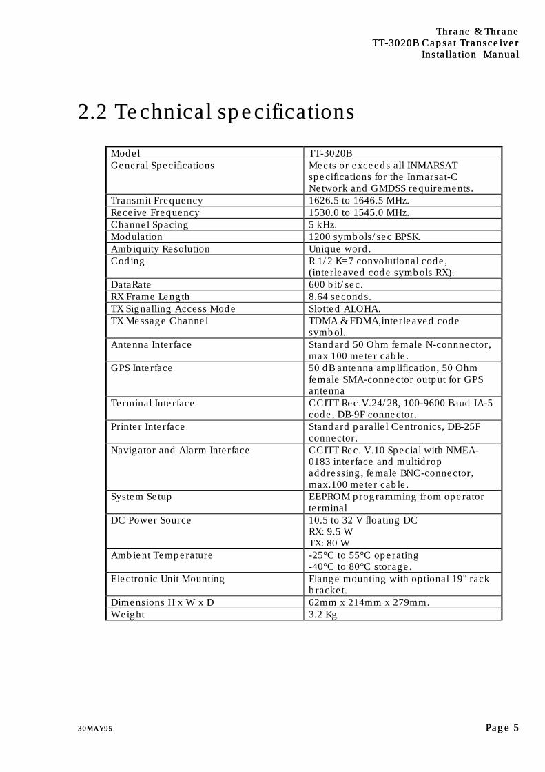
2.2 Technical specifications
Model TT-3020BGeneral Specifications Meets or exceeds all INMARSAT
specifications for the Inmarsat-CNetwork and GMDSS requirements.
Transmit Frequency 1626.5 to 1646.5 MHz.Receive Frequency 1530.0 to 1545.0 MHz.Channel Spacing 5 kHz.Modulation 1200 symbols/sec BPSK.Ambiquity Resolution Unique word.Coding R 1/2 K=7 convolutional code,
(interleaved code symbols RX).DataRate 600 bit/sec.RX Frame Length 8.64 seconds.TX Signalling Access Mode Slotted ALOHA.TX Message Channel TDMA & FDMA,interleaved code
symbol.Antenna Interface Standard 50 Ohm female N-connnector,
max 100 meter cable.GPS Interface 50 dB antenna amplification, 50 Ohm
female SMA-connector output for GPSantenna
Terminal Interface CCITT Rec.V.24/28, 100-9600 Baud IA-5code, DB-9F connector.
Printer Interface Standard parallel Centronics, DB-25Fconnector.
Navigator and Alarm Interface CCITT Rec. V.10 Special with NMEA-0183 interface and multidropaddressing, female BNC-connector,max.100 meter cable.
System Setup EEPROM programming from operatorterminal
DC Power Source 10.5 to 32 V floating DCRX: 9.5 WTX: 80 W
Ambient Temperature -25°C to 55°C operating-40°C to 80°C storage.
Electronic Unit Mounting Flange mounting with optional 19" rackbracket.
Dimensions H x W x D 62mm x 214mm x 279mm.Weight 3.2 Kg
Thrane & ThraneThrane & ThraneTTTT-3020B-3020B Capsat Transceiver Capsat TransceiverInstallation ManualInstallation Manual
Page Page 66 30MAY9530MAY95
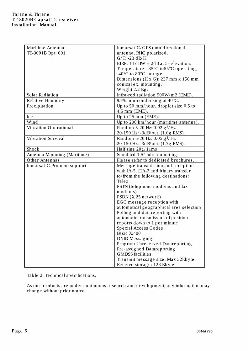
Maritime AntennaTT-3001B Opt. 001
Inmarsat-C/GPS omnidirectionalantenna, RHC polarized.G/T: -23 dB/KEIRP: 14 dBW ± 2dB at 5° elevation.Temperature: -35°C to55°C operating,-40°C to 80°C storage.Dimensions (H x G): 237 mm x 150 mmconical ex. mounting.Weight 2.2 Kg.
Solar Radiation Infra-red radiation 500W/m2 (EME).Relative Humidity 95% non-condensing at 40°C.Precipitation Up to 50 mm/hour, droplet size 0.5 to
4.5 mm (EME).Ice Up to 25 mm (EME).Wind Up to 200 km/hour (maritime antenna).Vibration Operational Random 5-20 Hz: 0.02 g2/Hz
20-150 Hz: -3dB/oct. (1.0g RMS).Vibration Survival Random 5-20 Hz: 0.05 g2/Hz
20-150 Hz: -3dB/oct. (1.7g RMS).Shock Half sine 20g/11msAntenna Mounting (Maritime) Standard 1.5" tube mounting.Other Antennas Please refer to dedicated brochures.Inmarsat-C Protocol support Message transmission and reception
with IA-5, ITA-2 and binary transferto/from the following destinations:TelexPSTN (telephone modems and faxmodems)PSDN (X.25 network)EGC message reception withautomatical geographical area selectionPolling and datareporting withautomatic transmission of positionreports down to 1 per minute.Special Access CodesBasic X.400DNID MessagingProgram Unreserved DatareportingPre-assigned DatareportingGMDSS facilities.Transmit message size: Max 32KbyteReceive storage: 128 Kbyte
Table 2: Technical specifications.
As our products are under continuous research and development, any information maychange without prior notice.

Thrane & ThraneThrane & ThraneTTTT-3020B-3020B Capsat Transceiver Capsat Transceiver
Installation ManualInstallation Manual
30MAY9530MAY95 Page Page 77
2.3 Power requirementsDepending on your particular TT-3000 System you will need AC supply or a DC supply.
A TT-3000 Integrated Capsat System operates on either 115 VAC, 220 VAC or floatingDC in the range from 10.5-32 Volt. The total power consumption varies with theparticular system in question.
As a guide-line, please note the power consumption of the following equipment:
TT-1542B Call Alarm 0.6 WTT-3022A Capsat Transceiver incl. antenna 9.5W RX 80W TXTT-3602D SVGA Monitor 60 WTT-3606A Message Terminal, incl keyboard. 8WTT-3608A Printer 33WTT-3042B Remote Alarm 2.5W 7W PrintOption 005 Built-in GPS 2W
Table 3: Capsat System component power requirements.
2.3.1 AC mains operationAs the TT-3020B Capsat Transceiver is designed to work on floating DC ranging from10.5 - 32 Volt, an AC/DC converter is needed in case the Transceiver is subject to workin AC environments.
2.3.1.1 Integrated Capsat System
For a TT-3000 Integrated Capsat System with an IBM compatible PC we recommend theTT-3680A Power Supply.
The TT-3680A Power Supply operates on either 115 VAC or 230 VAC. (internallyselectable) and supplies 24 VDC/96 Watt as a maximum.
The TT-3680A will adjust the DC output level (10.5 - 32 Volt) according to the total load.
The TT-3680A Power Supply may be connected to the emergency batteries offeringautomatic switch-over to DC in case of a mains line drop-out.
For a TT-3000 Integrated Capsat System with a TT-3608A Message Terminal werecommend the TT-3680B Power Supply.

Thrane & ThraneThrane & ThraneTTTT-3020B-3020B Capsat Transceiver Capsat TransceiverInstallation ManualInstallation Manual
Page Page 88 30MAY9530MAY95
The TT-3680B Power Supply operates on either 115 VAC or 230 VAC. (internallyselectable) and supplies 24 VDC/200 Watt as a maximum.
The TT-3680B will adjust the DC output level (10.5 - 32 Volt) according to the total load.
The TT-3680B Power Supply may be connected to the emergency batteries offeringautomatic switch-over to DC in case of a mains line drop-out.
2.3.1.2 Power connector
The battery connector matches the Thrane & Thrane standards for battery connectors.
Regardless whether the unit is designed to work on floating DC or modified to matchyour DC requirements the pin assignment of the DC/Battery power connector looks likethis:
PinPin NameName Signal DescriptionSignal Description1 SGND Safety Ground2 SUP+ Supply Voltage, positive terminal3 SUP- Supply Voltage, negative terminal4 ON/OFF Remote ON/OFF Switch
Table 4: TT-3020B Capsat Transceiver DC Power Connector pin assignment
Pin 4 is a unique feature for the TT-3020B Capsat Transceiver.
When this pin is left floating the Transceiver is turned off, but if pin 4 is shorted to thenegative terminal of the battery or DC-supply the Transceiver will switch on. Thismakes it possible for other equipment to perform remote power control of the TT-3020B.
The remote power control can be triggered by an external relay or solid state switch.
The battery connection is floating, i.e. there is no galvanic connection from any of thebattery poles to the cabinet frame.
Thrane & ThraneThrane & ThraneTTTT-3020B-3020B Capsat Transceiver Capsat Transceiver
Installation ManualInstallation Manual
30MAY9530MAY95 Page Page 99
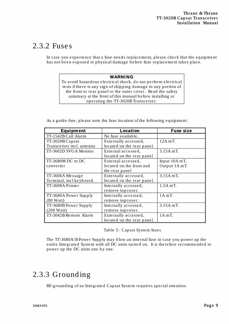
2.3.2 FusesIn case you experience that a fuse needs replacement, please check that the equipmenthas not been exposed to physical damage before fuse replacement takes place.
WARNINGWARNINGTo avoid hazardous electrical shock, do not perform electricaltests if there is any sign of shipping damage to any portion of
the front or rear panel or the outer cover. Read the safetysummary at the front of this manual before installing or
operating the TT-3020B Transceiver.
As a guide-line, please note the fuse location of the following equipment:
EquipmentEquipment LocationLocation Fuse sizeFuse sizeTT-1542B Call Alarm No fuse available.TT-3020B CapsatTransceiver incl. antenna
Externally accessed,located on the rear panel.
12A mT.
TT-3602D SVGA Monitor External accessed,located on the rear panel
3.15A mT.
TT-3680M DC to DCconverter
External accessed,located on the front andthe rear panel
Input 10A mT.Output 1A mT.
TT-3606A MessageTerminal, incl keyboard.
Externally accessed,located on the rear panel.
3.15A mT.
TT-3608A Printer Internally accessed,remove topcover.
1.5A mT.
TT-3680A Power Supply(80 Watt)
Internally accessed,remove topcover.
1A mT.
TT-3680B Power Supply(200 Watt)
Internally accessed,remove topcover.
3.15A mT.
TT-3042B Remote Alarm Externally accessed,located on the rear panel.
1A mT.
Table 5: Capsat System fuses
The TT-3680A/B Power Supply may blow an internal fuse in case you power up theentire Integrated System with all DC units turned on. It is therefore recommended topower up the DC units one by one.
2.3.3 GroundingRF-grounding of an Integrated Capsat System requires special attention.

Thrane & ThraneThrane & ThraneTTTT-3020B-3020B Capsat Transceiver Capsat TransceiverInstallation ManualInstallation Manual
Page Page 1010 30MAY9530MAY95
Each unit shall have its own individual low-inductance earth connection. The use of acommon busbar for grounding is not recommended as this can lead to unwantedcommon-mode coupling effects.
The ground should be connected to the cabinets metal frame to provide a return pathfor fault currents due to equipment malfunction or external faults such as lightning faults.
Interconnecting cables must be well screened.
Thrane & ThraneThrane & ThraneTTTT-3020B-3020B Capsat Transceiver Capsat Transceiver
Installation ManualInstallation Manual
30MAY9530MAY95 Page Page 1111
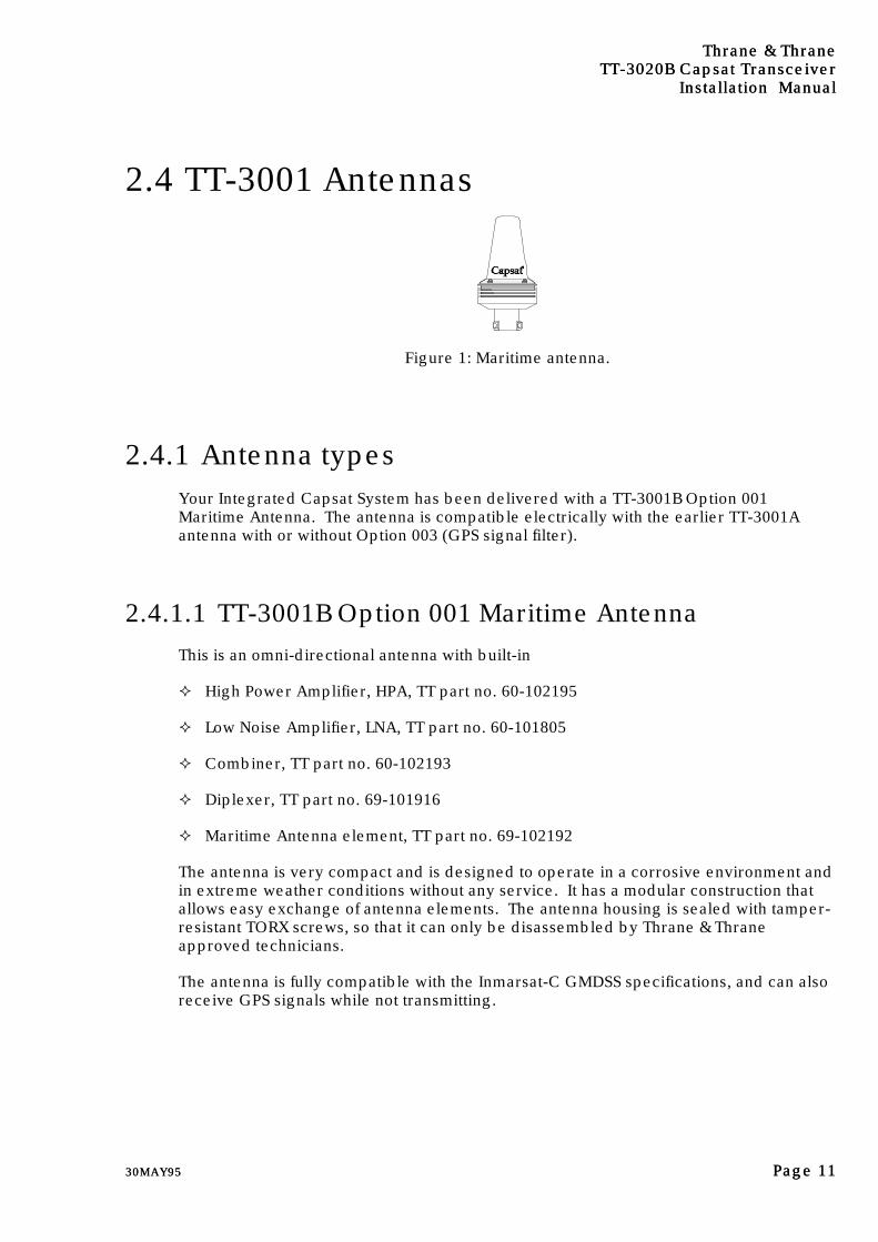
2.4 TT-3001 Antennas
Figure 1: Maritime antenna.
2.4.1 Antenna typesYour Integrated Capsat System has been delivered with a TT-3001B Option 001Maritime Antenna. The antenna is compatible electrically with the earlier TT-3001Aantenna with or without Option 003 (GPS signal filter).
2.4.1.1 TT-3001B Option 001 Maritime Antenna
This is an omni-directional antenna with built-in
² High Power Amplifier, HPA, TT part no. 60-102195
² Low Noise Amplifier, LNA, TT part no. 60-101805
² Combiner, TT part no. 60-102193
² Diplexer, TT part no. 69-101916
² Maritime Antenna element, TT part no. 69-102192
The antenna is very compact and is designed to operate in a corrosive environment andin extreme weather conditions without any service. It has a modular construction thatallows easy exchange of antenna elements. The antenna housing is sealed with tamper-resistant TORX screws, so that it can only be disassembled by Thrane & Thraneapproved technicians.
The antenna is fully compatible with the Inmarsat-C GMDSS specifications, and can alsoreceive GPS signals while not transmitting.
Thrane & ThraneThrane & ThraneTTTT-3020B-3020B Capsat Transceiver Capsat TransceiverInstallation ManualInstallation Manual
Page Page 1212 30MAY9530MAY95
2.4.2 Mounting bracketThe omnidirectional maintenance free antenna unit must be mounted in a high locationwith direct line-of-sight to the satellites.
Illustration of the 1½" Adaptor for mouting on a pole is enclosed in the back of thismanual.
The Adaptor may be removed by loosening the three Allan screws fitting the bracket tothe antenna.
2.4.3 Antenna connector"N" type connectors are available from manufacturers like:Suhner, Radial, Omnispectra, Kings, etc.
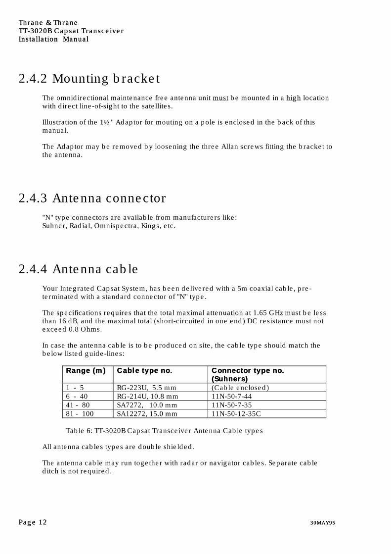
2.4.4 Antenna cableYour Integrated Capsat System, has been delivered with a 5m coaxial cable, pre-terminated with a standard connector of "N" type.
The specifications requires that the total maximal attenuation at 1.65 GHz must be lessthan 16 dB, and the maximal total (short-circuited in one end) DC resistance must notexceed 0.8 Ohms.
In case the antenna cable is to be produced on site, the cable type should match thebelow listed guide-lines:
Range (m)Range (m) Cable type no.Cable type no. Connector type no.Connector type no.(Suhners)(Suhners)
1 - 5 RG-223U, 5.5 mm (Cable enclosed)6 - 40 RG-214U, 10.8 mm 11N-50-7-4441 - 80 SA7272, 10.0 mm 11N-50-7-3581 - 100 SA12272, 15.0 mm 11N-50-12-35C
Table 6: TT-3020B Capsat Transceiver Antenna Cable types
All antenna cables types are double shielded.
The antenna cable may run together with radar or navigator cables. Separate cableditch is not required.
Thrane & ThraneThrane & ThraneTTTT-3020B-3020B Capsat Transceiver Capsat Transceiver
Installation ManualInstallation Manual
30MAY9530MAY95 Page Page 1313
If you install your system in a permanent location, we recommend that you, after theinstallation of the antenna, wrap the connector with the enclosed self-bonding tape,disabling water from penetrating the connection.
2.4.5 Mounting considerations
2.4.5.1 TT-3001B-opt. 001 Maritime Antenna
When installing the Maritime Antenna you should find a location on the vessel that is asfree from obstructions as possible. Also you should maintain a certain distance to otherantennas, especially radar installations. Normally the best place for the antenna wouldbe above radar scanning antennas. The following safe distances should be maintained:
Distance to HF antennas > 5 m
Distance to VHF antennas > 4 m
Distance to magnet compass > 3 m
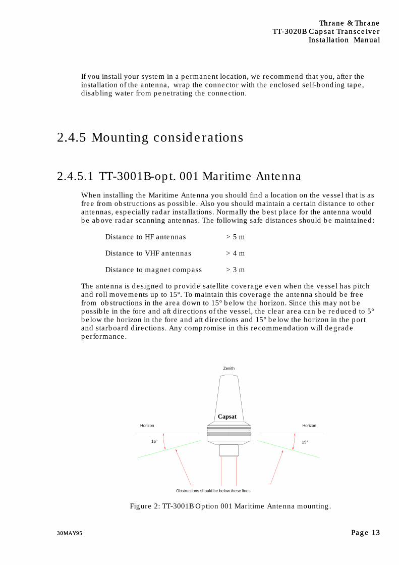
The antenna is designed to provide satellite coverage even when the vessel has pitchand roll movements up to 15°. To maintain this coverage the antenna should be freefrom obstructions in the area down to 15° below the horizon. Since this may not bepossible in the fore and aft directions of the vessel, the clear area can be reduced to 5°below the horizon in the fore and aft directions and 15° below the horizon in the portand starboard directions. Any compromise in this recommendation will degradeperformance.
15°
HorizonHorizon
Zenith
15°
Obstructions should be below these lines
Capsat
Figure 2: TT-3001B Option 001 Maritime Antenna mounting.
Thrane & ThraneThrane & ThraneTTTT-3020B-3020B Capsat Transceiver Capsat TransceiverInstallation ManualInstallation Manual
Page Page 1414 30MAY9530MAY95
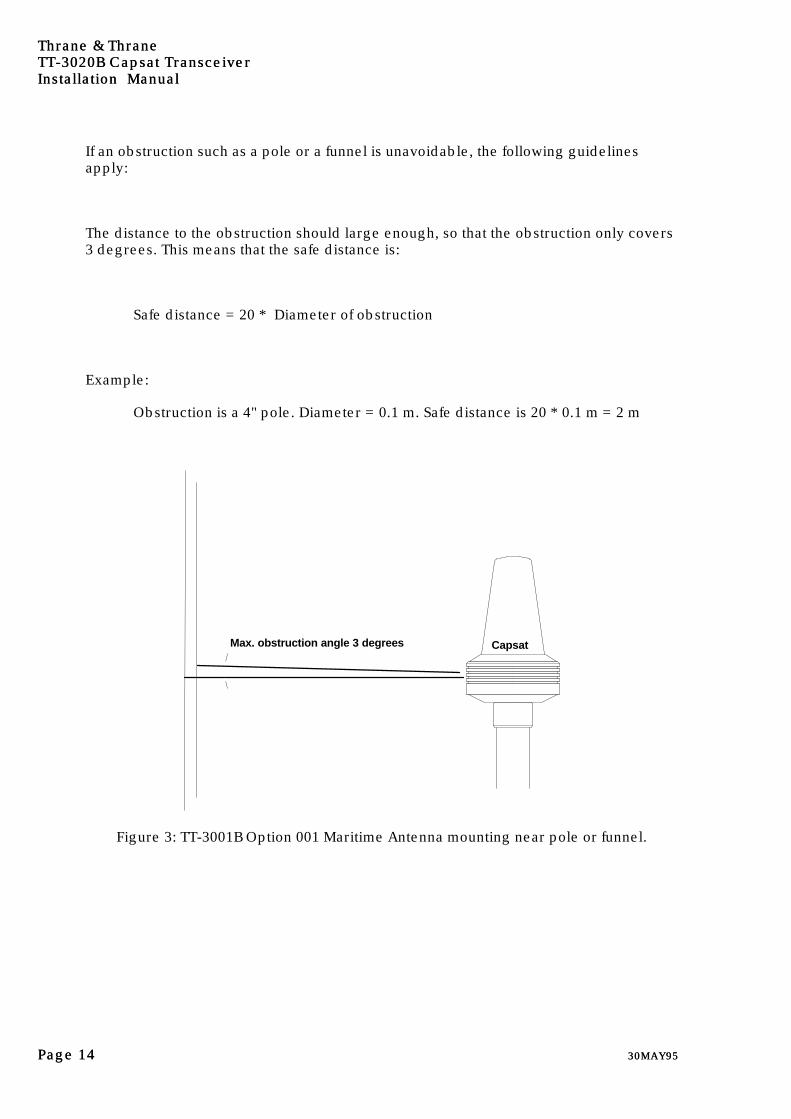
If an obstruction such as a pole or a funnel is unavoidable, the following guidelinesapply:
The distance to the obstruction should large enough, so that the obstruction only covers3 degrees. This means that the safe distance is:
Safe distance = 20 * Diameter of obstruction
Example:
Obstruction is a 4" pole. Diameter = 0.1 m. Safe distance is 20 * 0.1 m = 2 m
Max. obstruction angle 3 degrees Capsat
Figure 3: TT-3001B Option 001 Maritime Antenna mounting near pole or funnel.

Thrane & ThraneThrane & ThraneTTTT-3020B-3020B Capsat Transceiver Capsat Transceiver
Installation ManualInstallation Manual
30MAY9530MAY95 Page Page 1515
2.4.6 Safety Distance for Antenna UnitsThe safety levels for the Thrane & Thrane INMARSAT-C Antenna Units are based on theANSI standard C95.1-1982 "American National Standard Safety Levels With Respect toHuman Exposure to Radio Frequency Electromagnetic Fields, 300 kHz to 100 GHz"
This standard recommends the maximum power density at 1.6 GHz exposed to humanbeings not to exceed 5 mW/cm².
At the maximum radiated output power from the INMARSAT-C Antenna (16 dBW EIRP)this corresponds to a minimum safety distance on 30 cm.
To be sure that this distance is respected the Thrane & Thrane INMARSAT-C AntennaUnits are provided with a label declaring a minimum safety distance on 2 feet (61 cm).
In the future standards from the European Telecommunication Standard Institute (ETSI)concerning 1.5/1.6 GHz Satellite Earth Stations the recommendation will be maximum8W/m² (0.8 mW/cm²). This tighter recommendations correspond to a minimum safetydistance on 60 cm at 16 dBW, so these future European recommendations are alsocovered within the declared minimum safety distance on 2 feet (62 cm).

Thrane & ThraneThrane & ThraneTTTT-3020B-3020B Capsat Transceiver Capsat TransceiverInstallation ManualInstallation Manual
Page Page 1616 30MAY9530MAY95
2.5 TT-3020B Capsat Transceiver
Figure 4: TT-3020B Capsat Transceiver
2.5.1 Mounting bracketThe TT-3020B Capsat Transceiver is supplied with an universal mounting bracket (41-100562) which allows "over" or "under" mounting to e.g. a table or ceiling.
It is recommended that the Transceiver is mounted in an open air location allowing theoperator full access to the front panel in a distress situation.
When the Transceiver is used with other Thrane & Thrane equipment such as theTT-3606A Message Terminal or the TT-3210A Radiotelex Modem, stacked mounting maybe achieved using mounting bracket 41-100742.
It is strongly recommended not to stack mount the TT-3020B Capsat Transceiver withthe TT-3680A Power Supply because of the heat generation from this unit.
2.5.2 Communication portThe TT-3020B Capsat Transceiver communicates with a controller device via thestandard EIA RS-232D ports, located on the rear panel at X4.
2.5.2.1 Baudrate and protocol settings
The TT-3020B accepts the following:
Thrane & ThraneThrane & ThraneTTTT-3020B-3020B Capsat Transceiver Capsat Transceiver
Installation ManualInstallation Manual
30MAY9530MAY95 Page Page 1717
Baud ratesBaud rates Protocol settingsProtocol settings HandshakeHandshake110 Baud 7/8 databits Hardware150 Baud No/Even/Odd parity Using DTR and CTS300 Baud 1/2 stopbits600 Baud1200 Baud2400 Baud4800 Baud9600 Baud
Table 7: Automatic baudrate settings.
The serial port communication parameters are factory programmed to:
4800 Baud, 8 databits, no parity, 1 stopbit4800 Baud, 8 databits, no parity, 1 stopbit
Please refer to chapter section 3.3 to alter the baudrate and the protocol settings bymeans of Automatic Baud Rate Recognition.
Alternatively these settings may be customer defined.
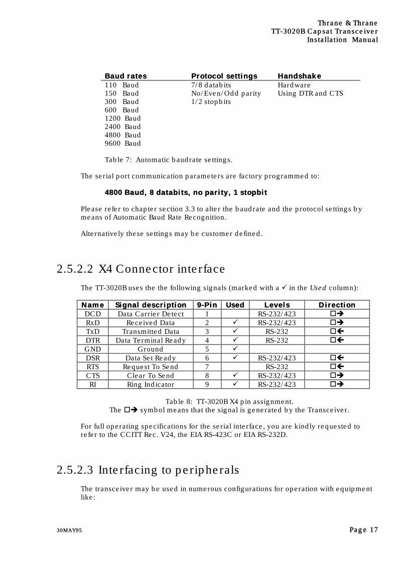
2.5.2.2 X4 Connector interface
The TT-3020B uses the the following signals (marked with a ü in the Used column):
NameName Signal descriptionSignal description 9-Pin9-Pin UsedUsed LevelsLevels DirectionDirectionDCD Data Carrier Detect 1 RS-232/423 oèRxD Received Data 2 ü RS-232/423 oèTxD Transmitted Data 3 ü RS-232 oçDTR Data Terminal Ready 4 ü RS-232 oçGND Ground 5 üDSR Data Set Ready 6 ü RS-232/423 oçRTS Request To Send 7 RS-232 oçCTS Clear To Send 8 ü RS-232/423 oèRI Ring Indicator 9 ü RS-232/423 oè
Table 8: TT-3020B X4 pin assignment.The oè symbol means that the signal is generated by the Transceiver.
For full operating specifications for the serial interface, you are kindly requested torefer to the CCITT Rec. V24, the EIA RS-423C or EIA RS-232D.
2.5.2.3 Interfacing to peripherals
The transceiver may be used in numerous configurations for operation with equipmentlike:

Thrane & ThraneThrane & ThraneTTTT-3020B-3020B Capsat Transceiver Capsat TransceiverInstallation ManualInstallation Manual
Page Page 1818 30MAY9530MAY95
² TT-3606A Message Terminal.
² IBM Compatible PC with a TT-10202A/B Message Terminal emulating software.
² Computerized equipment.
² Handheld terminals, etc.
2.5.2.3.1 TT-3606A Message Terminal
To Interface the TT-3020B to a TT-3606A Message Terminal, simply use the 30cmcommunication cable enclosed in the delivery (part no TT-61 100921).
An extended serial communication cable should not exceed 100 meters as the TT-3606Aworks on 4800 Baud using the RS-423 standard.
2.5.2.3.2 IBM Compatible PC (Personal Computer)
Interfacing the TT-3020B to a IBM Compatible PC, simply use the communication cableenclosed in the delivery: Either 9-9 pin (part no TT-61 100823) or 9-25 pin (part noTT-61 101034).
An extended communication cable should not exceed 8 meters as the TT-10202AMessage Terminal emulating software works on 4800 Baud using the RS-232C standard.
As the PC hardware normally does not conform to the RS-423 standard the maximumlength of the connection cable is less than for the TT-3606A solution.
As the TT-3020B rely on the CTS and DTR hardware handshake signals it is veryimportant that the PC you use is IBM hardware compatible with respect to the serialcommunications interface.
2.5.2.3.3 Computerized equipment
Before connecting the TT-3020B to any computerized equipment you are recommendedto consult the computer installation manual to check the pin assignment of the serialcommunication port.
Your TT-3020B is configured as Data Communications Equipment (DCE).
Most computers are configured as Data Terminal Equipment (DTE).If this is the case for the particular computer, you will probably be able to provide thenecessary connections with a multi-wire cable, as shown in the tables below:
Thrane & ThraneThrane & ThraneTTTT-3020B-3020B Capsat Transceiver Capsat Transceiver
Installation ManualInstallation Manual
30MAY9530MAY95 Page Page 1919
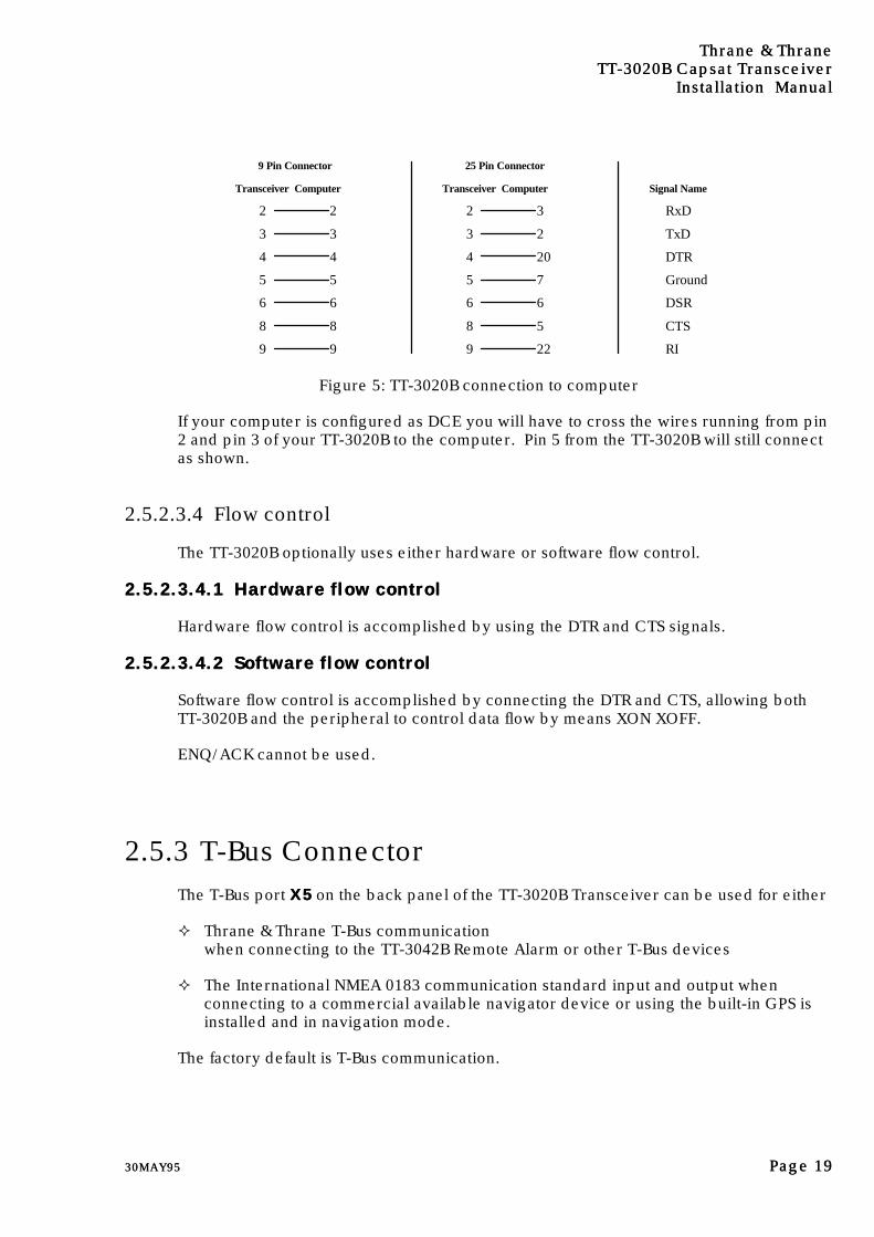
9 Pin Connector
Transceiver Computer
2 2
3 3
4 4
5 5
6 6
8 8
9 9
25 Pin Connector
2 3
3 2
4 20
5 7
6 6
8 5
9 22
RxD
TxD
DTR
Ground
DSR
CTS
RI
Signal NameTransceiver Computer
Figure 5: TT-3020B connection to computer
If your computer is configured as DCE you will have to cross the wires running from pin2 and pin 3 of your TT-3020B to the computer. Pin 5 from the TT-3020B will still connectas shown.
2.5.2.3.4 Flow control
The TT-3020B optionally uses either hardware or software flow control.
2.5.2.3.4.12.5.2.3.4.1 Hardware flow controlHardware flow control
Hardware flow control is accomplished by using the DTR and CTS signals.
2.5.2.3.4.22.5.2.3.4.2 Software flow controlSoftware flow control
Software flow control is accomplished by connecting the DTR and CTS, allowing bothTT-3020B and the peripheral to control data flow by means XON XOFF.
ENQ/ACK cannot be used.
2.5.3 T-Bus ConnectorThe T-Bus port X5X5 on the back panel of the TT-3020B Transceiver can be used for either
² Thrane & Thrane T-Bus communicationwhen connecting to the TT-3042B Remote Alarm or other T-Bus devices
² The International NMEA 0183 communication standard input and output whenconnecting to a commercial available navigator device or using the built-in GPS isinstalled and in navigation mode.
The factory default is T-Bus communication.
Thrane & ThraneThrane & ThraneTTTT-3020B-3020B Capsat Transceiver Capsat TransceiverInstallation ManualInstallation Manual
Page Page 2020 30MAY9530MAY95
The T-BUS connector, a standard BNC-type, is located on the rear panel of thetransceiver and is marked X5. The inner conductor carries the data signals and theouter is the shield.
2.5.3.1 Changing port X5 to input NMEA 0183 data
If the TT-3020B will be used with a navigator using the NMEA standard, you must followthe below instructions to ensure proper operation:
1. Turn off the TT-3020B .
2. Place the TT-3020B upside-down, remove all 9 screws so that the bottom covercan be removed.
3. Locate the switch array in the corner of the TT-3020B CPU board, and set switch 1and 3 in the OFF position. This selects NMEA input operation. Please refer tofigure 7 on page 21.
2.5.3.2 Changing port X5 to output NMEA 0183 data
If the TT-3020B will be used with an external device using the NMEA standard, you mustfollow the below instructions to ensure proper operation:
1. Turn off the TT-3020B .
2. Place the TT-3020B upside-down, remove all 9 screws so that the bottom covercan be removed.
3. Locate the switch array in the corner of the TT-3020B CPU board, and set switch 1in the OFF position and switch 3 in the ON position. This selects NMEA outputoperation. Please refer to figure 7 on page 21.
2.5.3.3 Changing port X5 to T-Bus communication
If the TT-3020B will be used with a TT-3042B Remote Alarm using the T-Bus standard,you must follow the below instructions to ensure proper operation:
1. Turn off the TT-3020B.
2. Place the TT-3020B upside-down, remove all 9 screws so that the bottom covercan be removed.
3. Locate the switch array in the corner of the TT-3020B CPU board, and set switch 1in the ON position. This selects T-Bus operation. Please refer to figure 7 on page21.

Thrane & ThraneThrane & ThraneTTTT-3020B-3020B Capsat Transceiver Capsat Transceiver
Installation ManualInstallation Manual
30MAY9530MAY95 Page Page 2121
2.5.4 Switch settingsFor location of the DIP (Dual-in-line) Switch Array see the following figure.
Figure 6: The DIP switches. Please refer to figure 7 on page 21.
SW.1 T-Bus ModeSW.2SW.3
RPU ModeNMEA 0183 Output
SW.6 Service ModeDS.1 T-Bus Activity: FlickersDS.2 Frame Decode: Toggles every 16sDS.3 CPU Activity: FlickersDS.4 TX dataTP.2 128 Hz Clock Adjustment
Printer T-Bus Console
Speaker
U6 EEPROM
U12 EPROM
DIP SwitchesU18 Viterbi EPROM
AlarmButton
PowerButton
SetButton
Power
CPU
GPS Module
Figure 7: TT-3020B CPU Board, No. TT 37-102819,showing the DIP Switch array.
Most of the DIP switches inside the TT-3020B Capsat Transceiver are reserved for futureuse.
Thrane & ThraneThrane & ThraneTTTT-3020B-3020B Capsat Transceiver Capsat TransceiverInstallation ManualInstallation Manual
Page Page 2222 30MAY9530MAY95
2.5.5 Jumper configurationsMuch of the flexibility of your TT-3020B Capsat Transceiver is due to the extensive useof operator programmable configuration parameters, enabling the user to adjust theTT-3020B to his specific application needs.
Most of the configuration parameters are contained in a single integrated circuit, a non-volatile EEPROM.
However, some parameters must be programmed by means of hardware jumpers orstraps on the main CPU board.
These jumper settings may easily be altered from their factory configuration to matchyour particular application.
2.5.5.1 Default configuration
The figure below summarize the jumper configurations and their use.
JumperJumper DefaultDefault FunctionFunctionW3
Pos 1-2Pos 2-3
Enable 12V or 5V supply to external GPS antenna.12V5V
Table 9: List of jumpers. You must not insert a jumper in any of the listed positions if youuse an built-in GPS (option 005)..
Warning:Warning:Do not attempt to change jumper settings unless you have thoroughunderstanding of their meaning.
2.5.6 Clock battery back-upThe clock in the transceiver is permanently backed-up by an internal non-chargeable 3Volt lithium battery. The service life of this battery exceeds 5 years.
If you turn off the TT-3020B Capsat Transceiver for a prolonged period this could drainyour battery. If your status screen indicates "Error in CMOS clock" in the first line, youmay need to change the battery.
If the battery wears out it must be replaced by qualified service personnel.
Please remember to logout of the Inmarsat-C system if you turn off the TT-3020B CapsatTransceiver for a prolonged period.
Thrane & ThraneThrane & ThraneTTTT-3020B-3020B Capsat Transceiver Capsat Transceiver
Installation ManualInstallation Manual
30MAY9530MAY95 Page Page 2323
2.5.7 NMEA 0183 Navigational InterfaceThe following Navigators will provide suitable NMEA 0183 strings to the CapsatTransceiver.
AP Navigator Professional APN5 GPSAP Navigator MK6Raytheon Raystar 920Furuno GP500 GPSFuruno GP1250 GPSFuruno GP70 GPSNavstar XR4 GPSDigital Northstar 800 LoranMicrologic Explorer GPSTrimble Navtrac XLShipmate RS 5300 GPSShipmate RS 4000 CC DeccaSperry 501 TR/GPS SatNav + Øverland interface unit UPL 2000Koden KGP 900 GPSKoden KGP 930 GPSKoden LR 771 Loran C
2.5.7.1 NMEA 0183 Reception
The NMEA 0183 Standard uses the ASCII alphabet to send strings with navigational data.This data can be read by the Transceiver via the T-Bus interface.
The following is a list of the NMEA codes that the Transceiver will recognize.
If the NMEA 0183 GLL string received by the Transceiver has an empty field the positioninformation will not be updated at all.
GLLGeographic position, latitude and longitudeIf the NMEA 0183 GLL string received by the Transceiver has an empty field theposition information will not be updated.
VTGHeading (track) and speed information
VHWHeading and speed information
HDTHeading information
HSCHeading information
Thrane & ThraneThrane & ThraneTTTT-3020B-3020B Capsat Transceiver Capsat TransceiverInstallation ManualInstallation Manual
Page Page 2424 30MAY9530MAY95
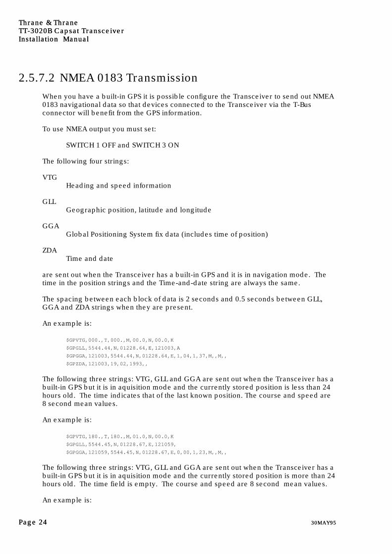
2.5.7.2 NMEA 0183 Transmission
When you have a built-in GPS it is possible configure the Transceiver to send out NMEA0183 navigational data so that devices connected to the Transceiver via the T-Busconnector will benefit from the GPS information.
To use NMEA output you must set:
SWITCH 1 OFF and SWITCH 3 ON
The following four strings:
VTGHeading and speed information
GLLGeographic position, latitude and longitude
GGAGlobal Positioning System fix data (includes time of position)
ZDATime and date
are sent out when the Transceiver has a built-in GPS and it is in navigation mode. Thetime in the position strings and the Time-and-date string are always the same.
The spacing between each block of data is 2 seconds and 0.5 seconds between GLL,GGA and ZDA strings when they are present.
An example is:
$GPVTG,000.,T,000.,M,00.0,N,00.0,K
$GPGLL,5544.44,N,01228.64,E,121003,A
$GPGGA,121003,5544.44,N,01228.64,E,1,04,1,37,M,,M,,
$GPZDA,121003,19,02,1993,,
The following three strings: VTG, GLL and GGA are sent out when the Transceiver has abuilt-in GPS but it is in aquisition mode and the currently stored position is less than 24hours old. The time indicates that of the last known position. The course and speed are8 second mean values.
An example is:
$GPVTG,180.,T,180.,M,01.0,N,00.0,K
$GPGLL,5544.45,N,01228.67,E,121059,
$GPGGA,121059,5544.45,N,01228.67,E,0,00,1,23,M,,M,,
The following three strings: VTG, GLL and GGA are sent out when the Transceiver has abuilt-in GPS but it is in aquisition mode and the currently stored position is more than 24hours old. The time field is empty. The course and speed are 8 second mean values.
An example is:

Thrane & ThraneThrane & ThraneTTTT-3020B-3020B Capsat Transceiver Capsat Transceiver
Installation ManualInstallation Manual
30MAY9530MAY95 Page Page 2525
$GPVTG,139.,T,139.,M,02.0,N,00.0,K
$GPGLL,5544.45,N,01228.68,E,,
$GPGGA,,5544.45,N,01228.68,E,0,00,1,0,M,,M,,
An empty GLL string is sent out when there is no built-in GPS or before the GPS modulehas been started by the Transceiver.
$GPGLL,,,,,,
$GPGLL,,,,,,
$GPGLL,,,,,,
Thrane & ThraneThrane & ThraneTTTT-3020B-3020B Capsat Transceiver Capsat TransceiverInstallation ManualInstallation Manual
Page Page 2626 30MAY9530MAY95
2.6 TT-3606A Message Terminal (optional)Please be advised that a special Reference Manual for the TT-3606A Message Terminalis available.
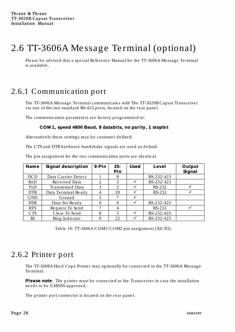
2.6.1 Communication portThe TT-3606A Message Terminal communicates with The TT-3020B Capsat Transceivervia one of the two standard RS-423 ports, located on the rear panel.
The communication parameters are factory programmed to:
COM1, speed 4800 Baud, 8 databits, no parity, 1 stopbitCOM1, speed 4800 Baud, 8 databits, no parity, 1 stopbit
Alternatively these settings may be customer defined.
The CTS and DTR hardware handshake signals are used as default.
The pin assignment for the two communication ports are identical.
NameName Signal descriptionSignal description 9-Pin9-Pin 25-25-PinPin
UsedUsed LevelLevel OutputOutputSignalSignal
DCD Data Carrier Detect 1 8 RS-232/423RxD Received Data 2 3 ü RS-232/423TxD Transmitted Data 3 2 ü RS-232 üDTR Data Terminal Ready 4 20 ü RS-232 üGND Ground 5 7 üDSR Data Set Ready 6 6 ü RS-232/423RTS Request To Send 7 4 RS-232 üCTS Clear To Send 8 5 ü RS-232/423RI Ring Indicator 9 22 ü RS-232/423
Table 10: TT-3606A COM1/COM2 pin assignment (X4/X3).
2.6.2 Printer portThe TT-3608A Hard Copy Printer may optionally be connected to the TT-3606A MessageTerminal.
Please notePlease note: The printer must be connected to the Transceiver in case the installationneeds to be GMDSS approved.
The printer port connector is located on the rear panel.
Thrane & ThraneThrane & ThraneTTTT-3020B-3020B Capsat Transceiver Capsat Transceiver
Installation ManualInstallation Manual
30MAY9530MAY95 Page Page 2727
This parallel interface conforms to the standard Centronics interface used e.g. on IBMcompatible PC's.
The enclosed standard cable allows the printer to be located up to 1.5 meters from theTT-3020B (or TT-3606A).
A special low-impedance cable is available for printer locations up to 20 meters fromTT-3020B (or TT-3606A)
Thrane & Thrane recommends that you always install the printer so that it is connectedto the Transceivers printer port.
2.6.3 VDU InterfacePlease be aware that your TT-3606A Message Terminal is delivered with a VideoMonitor Adapter offering connection to colour Video Monitors.
The adapter offers both analog and TTL video signals.
The video signals are available on X6 (TTL) and X7 (analog).
Regardless of the type of Video Monitor supplied with your Integrated Capsat System, itplugs into the Analog Video port, X7.
2.6.3.1 TT-3602D SVGA Monitor
The TT-3602D SVGA Monitor is connected to the Analog Video port, X7 on the TT-3606AMessage Terminal.
Figure 8: TT-3602D SVGA Video Monitor
Power:The TT-3602D SVGA Monitor can be supplied from either 180-280 Vac or by theTT-3680M DC to DC Converter.
Grounding:The TT-3602D SVGA does normally not require any separate grounding.

Thrane & ThraneThrane & ThraneTTTT-3020B-3020B Capsat Transceiver Capsat TransceiverInstallation ManualInstallation Manual
Page Page 2828 30MAY9530MAY95
2.6.3.2 TT-3680M DC to DC Converter (70Watt)
TT-3680M is a small DC to DC converter, operating in a wide input voltage range from10 to 32 Volts DC, generating a mains level DC output of 305 Volts, and capable ofpowering 70 Watts. The TT-3680M is designed for use with mains equipment where theinput is first rectified to produce a 305 Volts DC rail and then converted by a switchmode technique.
Due to the heat TT-3680M develops during operation it is recommended that this unit ismounted separately.
A separate installation manual for TT-3680M is available.
Figure 9: TT-3680M DC to DC Converter
2.6.4 TT-3601A keyboardThe TT-3601A Keyboard plugs into the X5 connector. You can use any PersonalComputer AT standard keyboard, but please be aware that if you choose a nationalkeyboard, that you may not be able to enter or transmit all of your national characters.
Power:The keyboard is powered from TT-3606A Message Terminal.
Grounding:TT-3601A Keyboard does normally not require any separate grounding.
Thrane & ThraneThrane & ThraneTTTT-3020B-3020B Capsat Transceiver Capsat Transceiver
Installation ManualInstallation Manual
30MAY9530MAY95 Page Page 2929
2.7 TT-3680A/B Power Supply (optional)The TT-3680A/B Power Supply operates on either 115 VAC or 230 Vac. (internallyselectable).
The TT-3680A/B Power Supply may be connected to the emergency batteries offeringautomatic switch-over to DC in case of a mains line drop-out.
2.7.1 TT-3680A Power Supply (80 Watt)The TT-3680A Power Supply supplies 24 Vdc/80 Watt as a maximum.
Due to the heat TT-3680A develops during operation it is recommended that this unit ismounted separately using the enclosed mounting bracket.
A separate installation manual for TT-3680A, is available.
Figure 10: 80W power supply.
2.7.2 TT-3680B Power Supply (200 Watt)The TT-3680B Power Supply supplies 20 Vdc/200 Watt as a maximum.
Due to the heat TT-3680B develops during operation it is recommended that this unit ismounted separately.
A separate installation manual for TT-3680B, is available.
Figure 11: 200W power supply.
Thrane & ThraneThrane & ThraneTTTT-3020B-3020B Capsat Transceiver Capsat TransceiverInstallation ManualInstallation Manual
Page Page 3030 30MAY9530MAY95
2.8 TT-3608A Hard Copy Printer
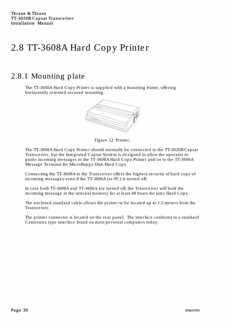
2.8.1 Mounting plateThe TT-3608A Hard Copy Printer is supplied with a mounting frame, offeringhorizontally oriented secured mounting.
Figure 12: Printer.
The TT-3608A Hard Copy Printer should normally be connected to the TT-3020B CapsatTransceiver, but the Integrated Capsat System is designed to allow the operator toguide incoming messages to the TT-3608A Hard Copy Printer and/or to the TT-3606AMessage Terminal for Microfloppy Disk Hard Copy.
Connecting the TT-3608A to the Transceiver offers the highest security of hard copy ofincoming messages even if the TT-3606A (or PC) is turned off.
In case both TT-3608A and TT-3606A are turned off, the Transceiver will hold theincoming message in the internal memory for at least 48 hours for later Hard Copy.
The enclosed standard cable allows the printer to be located up to 1.5 meters from theTransceiver.
The printer connector is located on the rear panel. The interface conforms to a standardCentronics type interface found on most personal computers today.

Thrane & ThraneThrane & ThraneTTTT-3020B-3020B Capsat Transceiver Capsat Transceiver
Installation ManualInstallation Manual
30MAY9530MAY95 Page Page 3131
PinPin NameName Signal DescriptionSignal Description Printer InputPrinter Input1 STRB Strobe ü2 DAT0 Data Bit 0 ü3 DAT1 Data Bit 1 ü4 DAT2 Data Bit 2 ü5 DAT3 Data Bit 3 ü6 DAT4 Data Bit 4 ü7 DAT5 Data Bit 5 ü8 DAT6 Data Bit 6 ü9 DAT7 Data Bit 7 ü
10 ACKN Acknowledge11 BUSY Printer Busy12 PE Paper End (out of paper)13 SEL Printer Selected14 ALFD Auto Line Feed ü15 ERR Printer Error16 INIT Initialize Printer ü17 SLCT Select Printer ü18 GND Ground19 GND Ground20 GND Ground21 GND Ground22 GND Ground23 GND Ground24 GND Ground25 GND Ground
Table 11: Printer port (X3) pin assignment. All signals use TTL voltage levels.

Thrane & ThraneThrane & ThraneTTTT-3020B-3020B Capsat Transceiver Capsat TransceiverInstallation ManualInstallation Manual
Page Page 3232 30MAY9530MAY95
2.9 TT-3042B Remote AlarmThe TT-3042B Remote Alarm is connected to the TT-3020B by means of the TransceiversX5 T-Bus connector. Please refer to section 2.5.3.
Figure 13: Remote Alarm with printer.
The TT-3042B Remote Alarm is intended for GMDSS installations.
The TT-3042B can all the same be used to print out SafetyNet EGC messages, via thebuilt-in thermal printer and indicate reception of EGC messages in general.
The TT-3020B Transceiver can accomodate up to 8 Remote Alarms at the same time, buteach alarm must have it's own unique T-Bus address in the range 0-7.
If more than one TT-3042B Remote Alarm is connected, the printer of the Remote Alarmwith the lowest address (first in the list of Remote Alarms seen with the ru -l command)will be used as the default printer, whereas the other printers will be back-up printersin case the first printer runs out of paper or has a malfunction.
If you do not connect a printer at the Transceiver, it will use the Remote Alarm printerinstead, but it is also possible to configure the Transceiver to use the Remote Alarmprinter always even if a Transceiver printer is available. Further you can select differenttypes of messages to go to either (or both) of the two printer types.
The Remote Alarm address is selected with a DIP Switch array inside Paper Bay of theTT-3042B. Please refer to the TT-3042B Remote Alarm Reference Manual for detailedinformation. The address selected for a Remote Alarm must not conflict with any otherRemote Alarm connected to the same TT-3020B Capsat Transceiver.
If you enter the Capsat Program's Terminal mode and type the command ru -l you willsee a list of the currently attached remote units and their addresses. In this way you willbe able to select unique addresses for all devices to be connected.
2.10 Built-in GPS (optional)GPS means Global Positioning System.

Thrane & ThraneThrane & ThraneTTTT-3020B-3020B Capsat Transceiver Capsat Transceiver
Installation ManualInstallation Manual
30MAY9530MAY95 Page Page 3333
The GPS module is installed from the factory and you need not perform any installtion touse it.
If you have ordered your Capsat Transceiver without a built-in GPS and you later needto install a GPS module, then you should contact your dealer to obtain the TechnicalReference Manual for instuctions on how to accomplish this.

Thrane & ThraneThrane & ThraneTTTT-3020B-3020B Capsat Transceiver Capsat TransceiverInstallation ManualInstallation Manual
Page Page 3434 30MAY9530MAY95
2.11 General interconnect informationBelow is an example of the TT-3000C Capsat System for maritime use.
You can find the other Integrated Capsat System available from Thrane & Thrane in theIntegrated Capsat Systems manual.
An Integrated Capsat System is delivered with all necessary interconnecting cables.
TT-3000C Capsat System CablingTT-3001B
Opt.001
Antenna TT-3020B
Transceiver
TT-3601AKeyboard
TT-3608APrinter
TT-3042BRemote Alarm
TT-3602DSVGA Monitor
TT-3606AMessage Term.
Option 002
403020-941, 5m X1
X2
37-101436, 0.2m X537-102282, 0.25m
X2 X3 88-360400-002, 2m
61-100921, 0.25m
X4
X5
X7X1
37-101128, 2m
37-101128, 2m
AC
X4
TT-3680MDC to DC Conv.
TT-3680BPower Supply
X2X137-103480, 3m
Figure 14: Interconnection diagram for integrated TT-3000C System.
Cable diagrams are enclosed in the back of this manual, in case extension cables needsto be prepared.
For applications where cables will be handmade by the dealer or the customer it isimportant to note that the cable screen should be soldered to the connector frame toprevent static electric shocks.
A complete set of connectors are delivered together with an Integrated Capsat System.Extra connector kits may be purchased separately.
Thrane & ThraneThrane & ThraneTTTT-3020B-3020B Capsat Transceiver Capsat Transceiver
Installation ManualInstallation Manual
30MAY9530MAY95 Page Page 3535
3.3. System GenerationSystem Generation
3.1 IntroductionThe System Generation is a special mode that the TT-3020B Capsat Transceiver canenter when powered ON. This mode allows you to change the general operation of theequipment before you start using it for communications.
The TT-3020B Capsat Transceiver has an enhanced level of System Parameter security.
The Transceiver will normally access and change System Parameters that are stored inthe non-volatile memory of the EEPROM chip, without any user intervention.
In the case that some of the special System Parameters needs to be changed, you willhave to permit the Transceiver to store these in the Protected part of the EEPROM. Thispart of the EEPROM memory can only changed if you press the SetSet button on thefrontpanel of the Transceiver.
This allows you to completely control when this information should be updated.
The information stored in the protected part of the EEPROM is:
The Thrane & Thrane serial number.
The main Network Coordinating Station Table.
The Mobile Type (Landmobile or Maritime).
The X4 connector serial communications settings.
For now you should only enter your Mobile Number and your Mobile Type.
The Mobile Type of your Transciver is Maritime, and this may already have beenentered for you by the person that installed your system.
In this case you only need to enter your Mobile Number.

Thrane & ThraneThrane & ThraneTTTT-3020B-3020B Capsat Transceiver Capsat TransceiverInstallation ManualInstallation Manual
Page Page 3636 30MAY9530MAY95
3.2 Terminal preparationAlteration of the TT-3020B Capsat Transceiver parameters may be accomplished bymeans of:
² TT-3606A Message Terminal.
² IBM compatible PC running DOS version 2.00 or later, with a communicationsoftware or theMessage Terminal emulating software TT-10202A/B.
² Computerized equipment.
² Handheld terminals, etc.
Please follow the below listed guide lines to set up the connected equipment in a directterminal emulating manner.
3.2.1 TT-3606A Message TerminalEnter the terminal emulation mode by selecting:
OPTIONS - CONFIGURATION - TERMINAL
3.2.2 IBM Compatible PCEnter the terminal emulation mode in the TT-10202A/B software by selecting:
OPTIONS - CONFIGURATION - TERMINAL
3.2.3 Computerized equipment/handheld terminalsYour computer/terminal should display the ASCII characters as they appear being sendfrom the TT-3020B Capsat Transceiver.
No alphabet or protocol conversion should take place.

Thrane & ThraneThrane & ThraneTTTT-3020B-3020B Capsat Transceiver Capsat Transceiver
Installation ManualInstallation Manual
30MAY9530MAY95 Page Page 3737
3.3 Entering the System GenerationThe procedure is as follows:
1. Turn on your Transceiver while you press the SetSet button. You must hold down thebutton for at least 10 seconds or at least until you can hear the connected printerbeing initialized.
2. Now hit the ENTERENTER key and watch the TT-3020B System Generation menu appearon your screen. If this does not happen, repeat steps 1 and 2.
3.4 The system generation menuHaving followed the instructions in the previous section you should now see the menuon your screen:
Thrane & Thrane system generation menu: Capsat Transceiver
0 Quit
1 Init system parameters
2 EGC settings
3 Filerouting
4 Reporting service
5 NCS Table
6 Preferred ocean
7 Console settings
8 Mobile Number
Enter number >
To perform an action on the list you just type in the appropriate number. If you want tosee the menu again just type CTRL+C (Hold the CTRL key down while typing a C).
The CTRL+C combination also acts as a Cancel facility. It will always bring you back tothe menu without changing any parameters.
Note:Note:Do not hit the ESCESC key if you use the Thrane & Thrane Message HandlingProgram. If you hit the ESC key you will go back to the menu of the MessageHandling Program and an error will occur as the Transceiver will not repond tothe normal commands while in the System Generation.
If you do hit ESC, then turn off both units and proceed as in section 3.3 on page37.

Thrane & ThraneThrane & ThraneTTTT-3020B-3020B Capsat Transceiver Capsat TransceiverInstallation ManualInstallation Manual
Page Page 3838 30MAY9530MAY95
3.4.1 Entering your mobile type and numberFor ease of operation and general information when you operate your Capsat system,you should consider to enter the mobile number.
Just type in the Inmarsat-C 9 digit number that you have received from your PTTauthorities.
An Inmarsat-C mobile number is always in the range:
400000000 to 499999999
If you type a number outside this range the Transceiver will ignore it.
You should not attempt to use your equipment before you have received a mobilenumber, because the Mobile Number means that you have been registred in thedatabase for the Inmarsat-C Network.
The Transceiver only uses the mobile number when sending Message Position Reports(see the Message Handling Software Operators Guide), to indicate which Transceiveroriginated the position message.
3.4.1.1 Fast access to the Mobile Type
You can get an easy first time installation, as the Transceiver will automaticallyrecognize if the mobile number has never been entered before, and automatically bringyou to the Change Mobile Type menu.
In this situation the Mobile Number will display as
Mobile number : (unknown)
You can only change the Mobile Type the first time you enter the System Generationand the status of the Mobile Type reads (unknown). If you see a Mobile Number here,then you may skip this step as it has been performed by your dealer.
The procedure of changing the Transceiver to Maritime is shown below:

Thrane & ThraneThrane & ThraneTTTT-3020B-3020B Capsat Transceiver Capsat Transceiver
Installation ManualInstallation Manual
30MAY9530MAY95 Page Page 3939
Mobile number : (unknown)
Mobile type : Illegal
Select Mobile Type:
0 Illegal
1 Landmobile
2 Maritime
Enter number > 2
Please use the Set function on the Capsat Transceiver
OK
Note that this can only be done once, as you cannot set the Mobile Number back to theunknown state. If you need to change the Mobile Type in this case, you need to contactyour dealer.

Thrane & ThraneThrane & ThraneTTTT-3020B-3020B Capsat Transceiver Capsat TransceiverInstallation ManualInstallation Manual
Page Page 4040 30MAY9530MAY95
3.5 Leaving the system generationThe following procedure will bring the Transceiver back to it's normal mode ofoperation.
1. Select menu entry 0 (zero) Quit, to leave the System Generation. The TT-3020Bwill ask you to use the SetSet function and hit the ENTERENTER key.
2. The TT-3020B Capsat Transceiver will perform a self test and start its programshowing you the software version and the stand-by prompt " : ".
3. If you use a Thrane & Thrane Message Handling Software you may now hit the ESCESCkey to get back to the window menu.

Thrane & ThraneThrane & ThraneTTTT-3020B-3020B Capsat Transceiver Capsat Transceiver
Installation ManualInstallation Manual
30MAY9530MAY95 Page Page 4141
4.4. Commissioning of theCommissioning of theequipmentequipment
4.1 IntroductionBefore the TT-3020B Capsat Transceiver is allowed to participate in the Inmarsat-CSystem, a commissioning procedure is required.
The commissioning procedure is just a the very first Link Test (or PerformanceVerification Test in Inmarsat terminology) that the Transceiver performs.
The Link Test automatically verifies that the TT-3020B Capsat Transceiver is capable ofboth receiving and transmitting information according to Inmarsat-C specifications. Noother tests are required.
The Inmarsat Mobile Number is needed to run the Link Test.
When a new unit is being installed, it is the responsibility of the service technician toverify that the unit is functioning properly, and that the unit is commissioned and loggedinto the Inmarsat-C System, at the end of installation.
When you power on the Transceiver for the very first time, it will automatically performa login. When the Inmarsat-C System sees this login, it will start a Link Test (orcommissioning procedure) after a short period of time.
Keep your equipment turned on and wait until the Link Test is finished before using theequipment for communications.
You should not attempt to start a Link Test yourself as you have only threecommissioning attempts, and these will be used up if you are not cautious.

Thrane & ThraneThrane & ThraneTTTT-3020B-3020B Capsat Transceiver Capsat TransceiverInstallation ManualInstallation Manual
Page Page 4242 30MAY9530MAY95
4.2 The first login (commissioning)The first login first login attempt from the unit (which is automatically performed by theTransceiver) will be recognized by the Network Coordinating Station (NCS) and servednormally, (downloading a Land Earth Station (LES) network table into the Transceiver)and inform the Network Database the new unit is present and being commissioned.
After the NCS has logged the unit into the Inmarsat-C Network, it instructs anpredefined LES to start a Link Test with the unit. The LES ID is stored in Inmarsat'sdatabase of mobile units.
When the Link Test is done, the TT-3020B Capsat Transceiver is logged in andcommissioned.
4.3 Overview of a Link TestThe Link Test consist of three parts:
² Message Reception Test
² Message Transmission Test and
² Distress Test.
The TT-3020B will ask you to perform a manual Distress Test but if you ignore therequest the Transceiver will automatically send the Distress Test after 2 minutes.
In the end of the test the Transceiver will receive the link test results.
Thrane & ThraneThrane & ThraneTTTT-3020B-3020B Capsat Transceiver Capsat Transceiver
Installation ManualInstallation Manual
30MAY9530MAY95 Page Page 4343
4.4 Details of a Link TestAs the first login performed by the Transceiver will cause the Commissioning (LinkTest) to take place. You should not try to start the link test yourself or try to send anymessages. If you do so, the NCS may find that your Transceiver does not respond to thecommissioning announcement, and will consequently change the status of your unit toBarred, and you will no longer be permitted to use the system.
After a while you will see a message on your screen and on your printer saying:
Link Test started
and when the MAIL indicator on the TT-3020B frontpanel starts flashing, the receive testhas commenced.
A test message is then received from the LES by the Transceiver.
After the MAIL indicator has turned OFF, the transmission test begins.
The SEND indicator starts flashing and after a while it will light continuously (the data isbeing transmitted) and then starts flashing again.
The SEND indicator will turn OFF when the protocol has finished.
The Transceiver will request you to perform a distress test. If you ignore this requestthe Transceiver will automatically send the Distress Test for you after 2 minutes, and theALARM indicator on the frontpanel will start blinking. When the distress has beenacknowledged by the LES the indicator will be on permanently.
If your Transceiver has been configured as Maritime, you will be prompted to send adistress and you must do so before the message disappears from the screen of theMessage Handling Program (if you do not use a Thrane & Thrane Message HandlingProgram, you must send the distress alert within 2 minutes after you receive theprompt). If you send a Distress yourself you will see the message "Distress issued andput in queue". You can ignore this.The printer will give an acknowledgement that the distress has been sent.After a successful distress transmission the printer will report this
The Transceiver now will wait for the test results to arrive from the LES, andacknowledge the reception of these by a short transmission (burst).
When receiving the results the screen will display:
- Link Test finished
and the results will be printed out.
The results of the test can also be viewed with:
- OPTION - LINK TEST

Thrane & ThraneThrane & ThraneTTTT-3020B-3020B Capsat Transceiver Capsat TransceiverInstallation ManualInstallation Manual
Page Page 4444 30MAY9530MAY95
To reset the red ALARM indicator, press the ALARM button only on the Transceiverfrontpanel for 5 seconds.
4.5 Commissioned statusWhen the commisioning procedure has been completed, the Transceiver will store thisstatus in it's non-volatile EEPROM memory.
A special feature of the Transceiver is that when it is commissioned it will check itscurrent login status when powered on.
If it is logged out, it will automatically issue a login to the last used NCS TDM.
4.6 Uncommissioned statusThough your TT-3020B Transceiver is not commissioned, it is fully capable of receivingmessages.
You are not denied permission to transmit messages by means of the TT-3020B CapsatTransceiver when your equipment is uncommissioned, but the LES will not forward yourmessages to their destinations, and a non-delivery notification is returned to you. Youmay also see the message "Your Transceiver is not commissioned" on the printer orscreen.
Any distress alerts will not be barred or rejected by the system.
Thrane & ThraneThrane & ThraneTTTT-3020B-3020B Capsat Transceiver Capsat Transceiver
Installation ManualInstallation Manual
30MAY9530MAY95 Page Page 4545
Index
—A——A—
AC mains operation, 7antenna connector, 12attenuation, 12
—B——B—
BNC-type connector, 20
—C——C—
Clock battery back-up, 22commissioning, 41
—D——D—
DC resistance, 12DC to DC converter, TT-3680M, 28DIP switch array, 21DTR and CTS signals, 19
—E——E—
EGC back-up printer, 32ETSI, 15
—F——F—
fuses, 9
—H——H—
hardware handshake signals, 18
—J——J—
jumper configurations, 22
—K——K—
keyboard, 28
—M——M—
making a serial cable, 18mobile number, 38mounting bracket, 16
—N——N—
navigator, 20NMEA 0183 communication, 19
—O——O—
omnidirectional antenna unit, 12
—P——P—
power connector, 8power requirements, 7printer port, 31Protected EEPROM, 35
—R——R—
radar or navigator cables, 12remote power control, 8RF grounding, 10RS-423 ports, 26
—S——S—
safety distance, 15SafetyNet EGC messages, 32self-bonding tape, 12serial communication cable length,
18serial port communication, 17shipping carton, 2storage temperature, 4SVGA, 27System Generation, 35system generation menu, 37
—T——T—
T Bus communication, 19TT 3022A COM port, 17TT 3042B Remote Alarm, 32TT 3606A COM port, 26TT-3601A Keyboard, 28TT-3602D SVGA Monitor, 27TT-3606A Message Terminal, 26TT-3608A Hard Copy Printer, 30TT-3680M DC to DC converter, 28TTL video signal, 27