tt-sense technical manual - insatech · optical thrust & torque sensor. for iom information of...
TRANSCRIPT

Technical Manual
Instructions for installation, operation and maintenance
664 TT-SENSE Optical Thrust and Torque Measuring systems
Publication nr TIB-664-GB-0113

CONTENTS 1. PREFACE ..................................................................................... 2
1.1 General ........................................................................................................ 2 1.2 Symbols ....................................................................................................... 2 1.3 Copyright ..................................................................................................... 2
2. SYSTEM DESCRIPTION .............................................................. 3 2.1 System description ....................................................................................... 3 2.2 System components .................................................................................... 3 2.3 Principle of operation ................................................................................... 3
3. TECHNICAL SPECIFICATION ...................................................... 6 3.1 Rotor ............................................................................................................ 6 3.2 Stator ........................................................................................................... 6 3.3 Specifications ............................................................................................... 6
4. SAFETY INSTRUCTIONS ............................................................. 7 4.1 Safety precautions ....................................................................................... 7
5. UNPACKING ................................................................................. 7
6. INSTALLATION ............................................................................. 8 6.1 TT-sense installation checklist ..................................................................... 8 6.2 Mechanical installation ................................................................................. 9 6.3 Electrical installation .................................................................................. 15 6.4 Zero setting ................................................................................................ 18 6.5 Miscellaneous ............................................................................................ 20
7. OPERATING INSTRUCTIONS .................................................... 22
8. MAINTENANCE .......................................................................... 22
9. SERVICE AND REPAIR INSTRUCTIONS ................................... 22
10. TAKE OUT OF SERVICE ........................................................ 22
11. REMOVAL AND STORAGE OF EQUIPMENT ........................ 22
12. MALFUNCTION AND SEND FOR REPAIR ............................. 23
13. ENVIRONMENT ...................................................................... 23
14. DISPOSAL .............................................................................. 23
15. TROUBLE SHOOTING ............................................................ 24
16. CERTIFICATES ....................................................................... 26
17. DRAWINGS ............................................................................. 27
18. ABBREVIATIONS .................................................................... 33
19. PARTS LISTS.......................................................................... 34 19.1 Stator part ............................................................................................... 34 19.2 Rotor part ................................................................................................ 35 19.3 Available spare parts for stator and rotor part ......................................... 36 19.4 Transport/mounting tools ........................................................................ 38 19.5 Installation tools ...................................................................................... 38
20. WARRANTY CONDITIONS ..................................................... 39

2
1. PREFACE 1.1 GENERAL This manual contains instructions for installation, operation and maintenance (IOM) of the TT Sense optical thrust & torque sensor. For IOM information of associated equipment supplied by VAF Instruments, refer to the separate manual supplied with those products. This manual contains important information for the installer, the operator and for your maintenance department.
To ensure safe and correct installation and operation, read this manual completely before installing the equipment and starting operations.
For any additional information contact:
VAF Instruments B.V. Tel. +31 78 618 3100 Vierlinghstraat 24, 3316 EL Dordrecht Fax +31 78 617 7068 P.O. Box 40, NL-3300 AA Dordrecht E-mail: The Netherlands
[email protected] Internet:
www.vaf.nl
Or your local authorized VAF dealer. Their addresses can be found on
www.vaf.nl
1.2 SYMBOLS The following symbols are used to call attention to specific types of information.
A warning to use caution! In some instances, personal injury or damage to the torque sensor or control system may result if these instructions are not followed properly.
An explanation or information of interest.
1.3 COPYRIGHT This technical manual is copyrighted with all rights reserved. While every precaution has been taken in the preparation of this manual, no responsibility for errors or omissions is assumed. Neither is any liability assumed for damages resulting from the use of the information contained herein. Specifications can be changed without notice.

3
2. SYSTEM DESCRIPTION 2.1 SYSTEM DESCRIPTION The TT-Sense optical thrust & torque sensor is intended for the measurement of torque, shaft power and propeller thrust. The output can be used for power measurement, power consumption management, engine management and measurement of propeller efficiency and hull resistance.
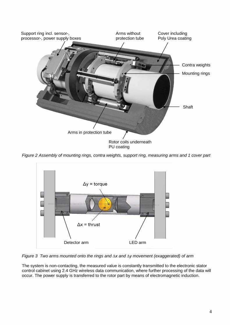
2.2 SYSTEM COMPONENTS The TT-Sense optical thrust & torque sensor consists of three main components: 1. The optical sensors on the shaft (rotor) 2. The stator pedestal with coil and antenna 3. The electronic control box holding the data receiver, power supply and the data output. The sensor is clamped onto the shaft by means of three rings. By tightening the bolts, the forces will be strong enough to create a stable connection between sensor and shaft. Two rings hold the measuring arms, which form the heart of the system. One arm holds a LED and the other one holds an optical detector, which is able to detect the movement of one ring in respect to the other. This movement is a measure for torque (∆y movement) and thrust (∆x movement) when the shaft properties are known. The analogue measuring data of the ∆y and ∆x movement is together with temperature and rpm data converted to digital data. Power to the sensor is transmitted through an inductive coupling between stator and rotor coils. Information between rotor and stator is transmitted by 2.4 GHz wireless data communication. In the control box, the stator processes the raw measurement data into signals that can be send to a digital or analogue output. 2.3 PRINCIPLE OF OPERATION When a shaft is subjected to torque (M), sheer will occur in the shaft. As a result two points on the shaft will move in respect to each other. This movement ∆y is a measure for the torque (fig 1). When an axial force is compressing the shaft, the length of the shaft will consequently decrease. This movement ∆x is a measure for thrust (T) induced by the propeller on the shaft (fig 1).
Figure1 Torque, Thrust and consequential ∆y and ∆x movement The movement is measured by mounting two rings on the shaft (see fig. 2). On either ring an measuring arm is attached, partly overleaping each other. On one of the arms a light source is mounted, on the other a photo-electric sensor. This sensor will register any movement of the spot, induced by the movement of the rings. By knowing the distance between the rings and the dimensions of the shaft, the torque and thrust can be calculated.
4
Figure 2 Assembly of mounting rings, contra weights, support ring, measuring arms and 1 cover part
Figure 3 Two arms mounted onto the rings and ∆x and ∆y movement (exaggerated) of arm The system is non-contacting, the measured value is constantly transmitted to the electronic stator control cabinet using 2.4 GHz wireless data communication, where further processing of the data will occur. The power supply is transferred to the rotor part by means of electromagnetic induction.
Mounting rings
Arms without protection tube
Cover including Poly Urea coating
Rotor coils underneath PU coating
Contra weights
Support ring incl. sensor-, processor-, power supply boxes
Arms in protection tube
LED arm Detector arm
Shaft

5
Figure 4 Schematic overview of TT-Sense thrust & torque measurement system with touchscreen display (optional) For more detailed information on a TT-Sense system including flowmeters and or speedlog/GPS input we like to refer to Technical Installation Manual TIB-662

6
3. TECHNICAL SPECIFICATION 3.1 ROTOR
• Power supply 40 Watt through inductive coupling Rotor input:
• Wireless 2.4 GHz fully protected encrypted signal • Master / slave mode
• Thrust data Rotor output through a 2.4 GHz wireless data communication:
• Torque data • RPM data • Position sensors • Temperature data (for internal calculation purpose only) • Diagnostic information (internal use only)
3.2 STATOR
• Supply 115 / 230 VAC ± 10% Stator input:
• Wireless 2.4 GHz fully protected encrypted signal from rotor • Calibration button
Stator output:
3.3 SPECIFICATIONS
Measurement specifications:
• Thrust [kN] <1,0% FSD (depending on application) • Torque [kNm] <0,5% FSD • Speed [rpm] <0,5% FSD • Power [kW]
Environmental data:
• Operating temperature 0 – 60°C • Storage -20 – 70°C • 1,5 x max. centrifugal force • Vibrations as per classification society, 0-100 Hz @ 4,0 g • EMC according EN 61000 • Protection degree stator control box IP65
Output RS485 Ethernet 4-20 mA SD Card Thrust X Optional Optional Torque X Optional Optional Speed X Optional Optional Shaft Power X Optional Optional Service/diagnostic X Firmware update X

7
• Shaft diameters 200 to 1000 mm Dimensions:
• Length rotor 734 mm (please note that extra space is required for installation) • Height rotor 150 mm • Distance rotor / stator approx. 3 mm • Stator coil bracket dimensions (BxHxD) 248x290x108 mm • Stator control box (BxHxD) 407x360x119 mm
Clamp-on system with rings, to be installed by qualified personnel. Mounting:
Rings : C45E Materials:
Arms : C45E Cover : Poly Urea coated High Density foam Protection tube : Aluminium
4. SAFETY INSTRUCTIONS 4.1 SAFETY PRECAUTIONS To ensure the safety of personnel and equipment: • Always follow the safety and installation recommendations in this manual. • Always use personal protective means when working with hot, aggressive and toxic process
liquids. • Always use insulated tools when working on electrical installations. • Ensure that local safety regulations are met when installing and operating the equipment. • All personnel who operate and service the equipment should read this manual completely and
make themselves acquainted with the equipment before installing or operating the equipment. • Do not work on TT-Sense optical torque sensor while rotating. • Disconnect power supply before opening cabinet or working on electronics.
5. UNPACKING Let the instruments acclimatize in the location where they are going to be installed for at least one hour inside their shipment box. This is to avoid moisture buildup inside the instrument, or on the connectors and wires. When the equipment is taken out of the box, please leave the transport locking materials for arms and between rings in place as long as possible to avoid any damage. Dispose of the packing material should be done according to the laws of the country where the equipment is installed or according to the rules that are applicable on the vessel.

8
6. INSTALLATION 6.1 TT-SENSE INSTALLATION CHECKLIST Before starting up the installation of the TT-Sense equipment please read this checklist to be aware of the chronological order for installation and commissioning of the TT-Sense equipment. 1. Prepare the pedestal foundation and installation of the stator pedestal and stator coil
Chapter 17 drawing 0815-1012, 0815-1013, 0815-1015, 0815-1212 and additional drawings
for the stator pedestal (optional delivery) 0815-1008 and 0815-1014.
2. Clean the shaft at the location of the rotor partsParagraph 6.2 Mechanical Installation
3. Follow and finish the mechanical installation instructions for the rotor part
Paragraph 6.2 Mechanical Installation
4. Follow and finish the electrical installation instructions regarding cabling of the control box
Paragraph 6.3 Electrical Installation
5. Start the ZERO SETTING procedure
Paragraph 6.4 of this technical manual
after fulfilling above installation instructions and after checking the integrity of external wiring.
6. If optional touch screen display(s) and/or a PEM2 Signal Processing Unit are to be connected to
the torque sensor
Technical Manual TIB662
, please read the instructions in the PEM2 manual and install these electrical components
7.
The TT-Sense system is ready for use

9
6.2 MECHANICAL INSTALLATION 1 Clean shaft
Clean the shaft thoroughly. Remove grease and rust particles from shaft.
2 Friction parts and ring assembly
Make sure that friction parts on mounting rings are clean. (No grease, no dirt particles) If friction parts are dirty, clean them with a clean cloth. Remove grease with degreasing detergent. Distance between the fork joints should be approx. 40 mm.
3 Mounting rotor parts on the shaft
Fix both rotor parts on the shaft by mounting the pins and the locking rings at the lower part.
Pin Locking ring
40
10
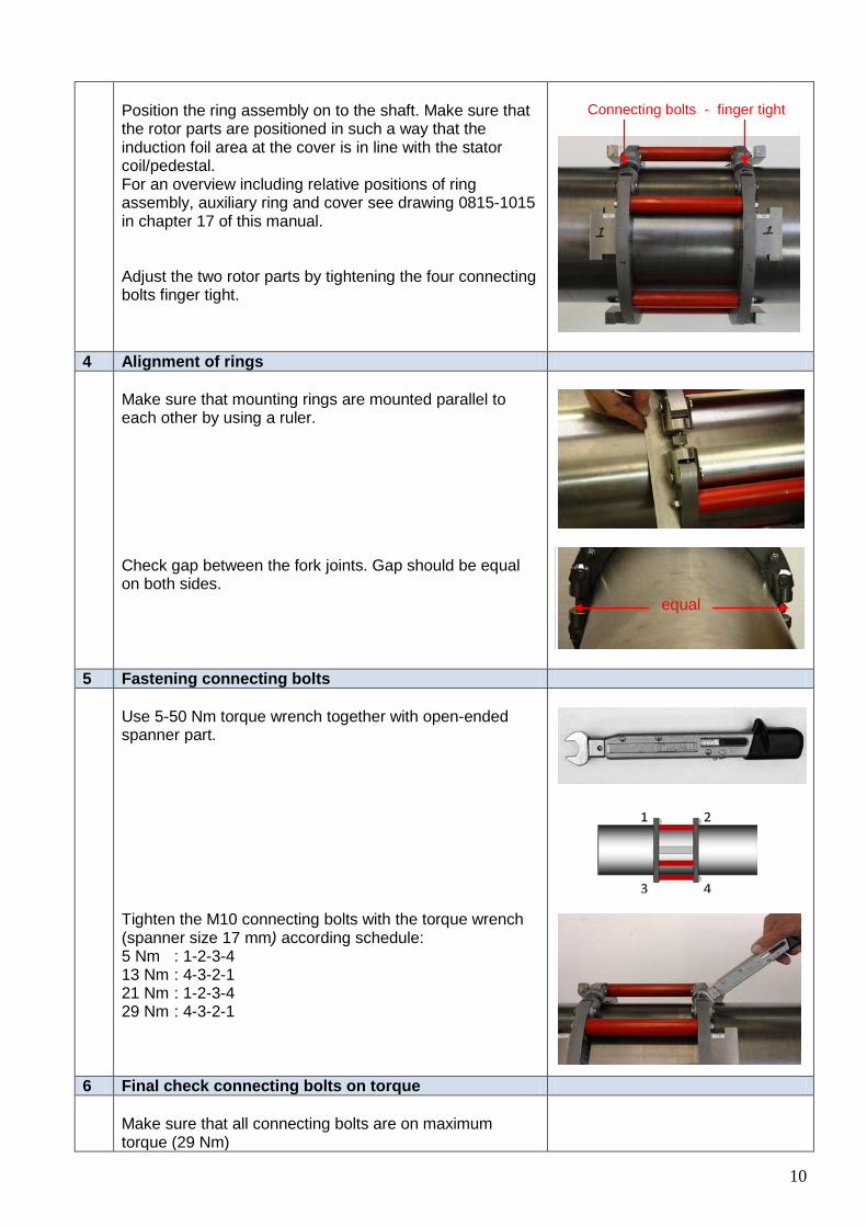
Position the ring assembly on to the shaft. Make sure that the rotor parts are positioned in such a way that the induction foil area at the cover is in line with the stator coil/pedestal. For an overview including relative positions of ring assembly, auxiliary ring and cover see drawing 0815-1015 in chapter 17 of this manual. Adjust the two rotor parts by tightening the four connecting bolts finger tight.
Connecting bolts - finger tight
4 Alignment of rings
Make sure that mounting rings are mounted parallel to each other by using a ruler. Check gap between the fork joints. Gap should be equal on both sides.
5 Fastening connecting bolts
Use 5-50 Nm torque wrench together with open-ended spanner part. Tighten the M10 connecting bolts with the torque wrench (spanner size 17 mm) according schedule: 5 Nm : 1-2-3-4 13 Nm : 4-3-2-1 21 Nm : 1-2-3-4 29 Nm : 4-3-2-1
6 Final check connecting bolts on torque
Make sure that all connecting bolts are on maximum torque (29 Nm)
equal

11
7 Removing spacers
Loosen the nuts and remove the threaded rods by hand. Remove the spacers between the rings by hand. Make sure that they can be removed without clearance and without significant resistance. When the spacers are having significant resistance or significant clearance, the rings are not aligned properly. This can cause incorrect measurements because the sensor can be out of range. Correct alignment of the rings is crucial for accurate measurements. Important
: Put spacers in supplied spare part box, as they are necessary for reinstallation.
8 Mounting the sensors
Make sure that the Detector side of the sensors is positioned at the side where the Rotor Auxiliary ring containing the electronic boxes will be mounted. The Detector side of the sensors is marked with character D on the mounting plate. (LED side is marked with L) Make sure that sensor 1, 2, 3 and 4 are mounted at the same radial position as the sensor boxes 1, 2, 3 and 4. Important:
The sensor should be able to easily slide between the rings. This should be done by hand only. When it is required to use tools, this is indicating the rotor is not correctly aligned. This will require re-alignment of the rings.
Bring the sensors socket head screws, of which nr. 2 and 3 are accessible through the holes in the counterweights, gradually on a maximum torque of 14,5 Nm. Tighten the socket head screws with a torque wrench according schedule: 5 Nm : 1-2-3 10 Nm : 1-2-3 14,5 Nm: 1-2-3
Socket head screws
9 Removing mounting plates
Remove the mounting plates, which are located on top of the sensors by loosening the 2 socket head screws. Disconnect the mounting plates by hand. Please read next instruction when removing mounting plate by hand is difficult.
without clearance/ resistance
2 3 1
D(detector-side)
12
If the mounting plate cannot be removed by hand easily, then insert the socket head screws in the holes to lift the mounting plate. Important
The mounting plate is dedicated for this specific sensor.
: Mounting plate should be stored in spare parts box and is needed when sensor is removed and re-assembled.
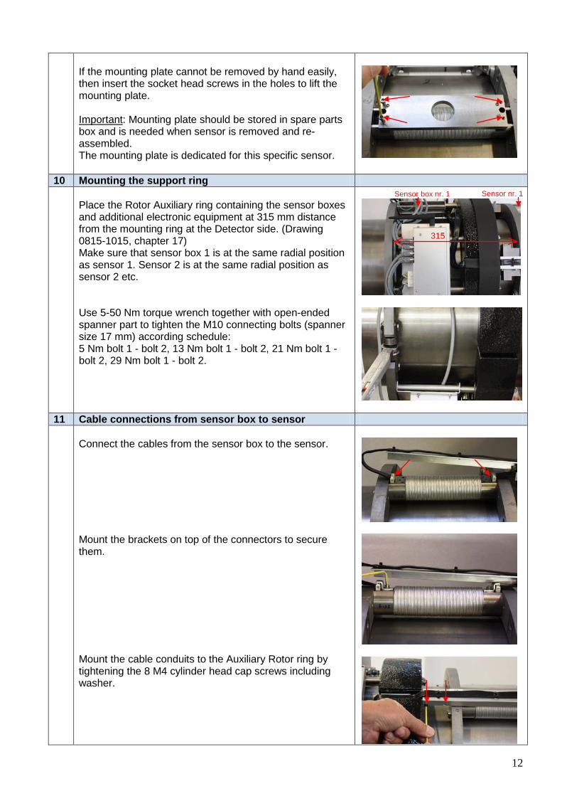
10 Mounting the support ring
Place the Rotor Auxiliary ring containing the sensor boxes and additional electronic equipment at 315 mm distance from the mounting ring at the Detector side. (Drawing 0815-1015, chapter 17) Make sure that sensor box 1 is at the same radial position as sensor 1. Sensor 2 is at the same radial position as sensor 2 etc. Use 5-50 Nm torque wrench together with open-ended spanner part to tighten the M10 connecting bolts (spanner size 17 mm) according schedule: 5 Nm bolt 1 - bolt 2, 13 Nm bolt 1 - bolt 2, 21 Nm bolt 1 - bolt 2, 29 Nm bolt 1 - bolt 2.
11 Cable connections from sensor box to sensor
Connect the cables from the sensor box to the sensor. Mount the brackets on top of the connectors to secure them. Mount the cable conduits to the Auxiliary Rotor ring by tightening the 8 M4 cylinder head cap screws including washer.
315
Sensor box nr. 1 Sensor nr. 1
13
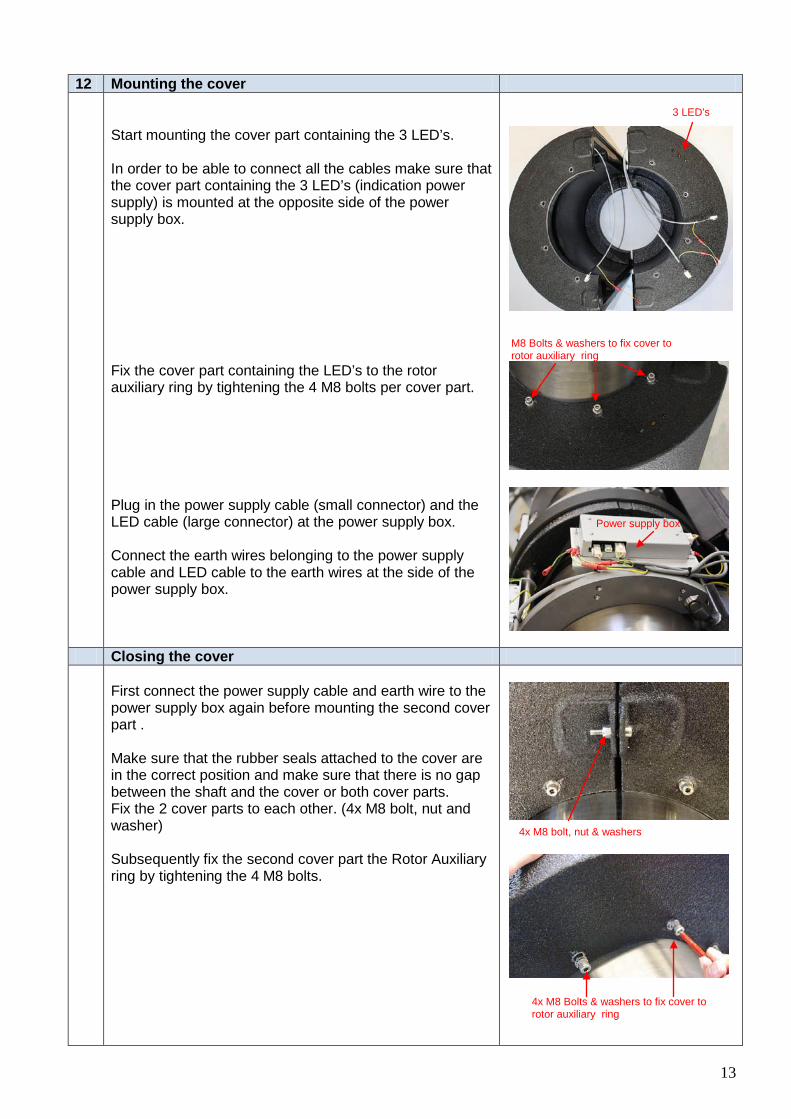
12 Mounting the cover
Start mounting the cover part containing the 3 LED’s. In order to be able to connect all the cables make sure that the cover part containing the 3 LED’s (indication power supply) is mounted at the opposite side of the power supply box. Fix the cover part containing the LED’s to the rotor auxiliary ring by tightening the 4 M8 bolts per cover part. Plug in the power supply cable (small connector) and the LED cable (large connector) at the power supply box. Connect the earth wires belonging to the power supply cable and LED cable to the earth wires at the side of the power supply box.
Closing the cover
First connect the power supply cable and earth wire to the power supply box again before mounting the second cover part . Make sure that the rubber seals attached to the cover are in the correct position and make sure that there is no gap between the shaft and the cover or both cover parts. Fix the 2 cover parts to each other. (4x M8 bolt, nut and washer) Subsequently fix the second cover part the Rotor Auxiliary ring by tightening the 4 M8 bolts.
Power supply box
4x M8 Bolts & washers to fix cover to rotor auxiliary ring
4x M8 bolt, nut & washers
3 LED’s
M8 Bolts & washers to fix cover to rotor auxiliary ring

14
13 Position of stator pedestal/coil
The stator coil will be delivered together with a bracket and 5 meter antenna cable and power supply cable, which will be connected to the TT-Sense control box.
Do not shorten or lengthen these cables! Important:
Stator coil to be positioned in line with the cover side. Make sure that the coil is at the same side as the foil in the rotor cover. (Drawing 0815-1015, chapter 17) Delivery of stator pedestal is optional. Centre of coil should be positioned at 3 mm from the cover at the same vertical level as the centerline of the shaft. Loosen the bolts at the stator bracket and/or coil for fine-adjustment of the vertical position and clearance between coil and cover. Use the 3 mm thick rubber mat to precisely adjust the clearance between coil and cover. Alternatively the stator coil can be placed horizontally above the cover or under the cover in the 2 positions as shown in the pictures.
Centre of coil should always be above or below the horizontal centerline of the shaft.
Important:
Standard position
3 mm clearance
3 mm clearance
3 mm clearance
Bolts
Bolts
Coil in line with cover side
Area with foil
Pedestal

15
6.3 ELECTRICAL INSTALLATION
Control box and cable connections MODbus cable to touchscreen display, PEM2 interfacebox or ship’s monitoring system, power supply cable and power and antenna cable to stator coil should be connected to the control box as indicated in below picture and the electrical connection diagram on the next page. For electrical connection diagrams of the total TT-Sense system with optional touch screen display see paragraph 17 Drawings.
Important note:
Please be aware that the control will have to be installed in the vicinity of the stator coil. Cable length from coil to control box is 5 m as a standard. Do not lengthen or shorten these cables.
Power to coil
115-230V AC Power supply
MODbus RS485 output
Antenna cable

16
Make sure that the power supply and MODbus cables are according the cable specification on page 25.
LNPE B A
LPOWER SUPPLY
115/230 VACRS485 MODBUS
OUTPUT
POWER TO COIL
Gnd
Under cable gland
Under cable gland
CONTROL BOX
ANTENNACABLE
Figure 5 Connection diagram for power supply control box, power supply to stator coil, MODbus output and antenna input
Important note:
Fold back the cable screens and clamp them under the cable glands like indicated in the pictures below.

17
Important note:
In case boardnet is 115 V ± 10% make sure that the voltage selector at the stator power supply PCB is set to 115 V before the control box is connected to its power supply. In case you select the wrong voltage the stator power supply will not work or the fuses at the PCB will be damaged.
If the control box is connected to the 115/230 V AC board net and the stator coil is connected to the control box, the 3 LED’s at the cover side will indicate that power is available at the rotor part. Please continue with paragraph 6.4 ZERO SETTING.
If power is not available please see Chapter 15 – TROUBLE SHOOTING
115-230V Voltage Selector

18
6.4 ZERO SETTING Purpose of the zero torque setting procedure is to compensate for any torque or thrust left when the shaft is in rest situation. Procedure: 1. Open the control box by removing 4 socket head cap screws.
On the bottom right hand side are two LED’s and a push button located.
Figure 6 Push button and LED’s for zero setting procedure
2.
After 10 seconds the green LED starts to flash. Press the push button until the green LED is on.
3.
When turning the shaft, make sure that the LED’s at the cover stay indicating that power is available during the full rotation of the rotor. If not the diagnostic LED in the control box will display error 96 (see paragraph 15).
Rotate the shaft in any direction by means of the engines shaft turning device until the green LED stops flashing.
4. Do not stop or reverse direction during turning.
The yellow LED starts to flash.
5. Rotate the shaft in opposite direction until the yellow LED stops flashing and both LED’s remain on continuously.
Do not stop or reverse direction during turning.
6. Press the push button for a short period (approx. 1 sec.) to leave the ‘zero setting mode’.
Both LED’s are off.
7. System zero torque and thrust have been set. Still a small torque value can be indicated as due to friction a small amount of torque can be present.
Close the cabinet
In case both LED’s flash alternating go to the ‘Error procedure’. If the zero setting procedure is completed the TT-Sense torque measuring system is ready for use. When an optional PEM2 touch screen display and PEM2 Signal Processing Unit are included in the scope of supply technical information is available in Technical Manual 662
Push button and LED’s

19
Error procedure:
Make sure that the shaft is not stopped or is making a (short) reverse rotation. 1. Press the push button to leave the ‘zero setting mode’. 2. Repeat the procedure for zero setting.
Additional info:
- When the system is left in ’zero setting mode’ it will automatically return in running mode after 15 minutes.

20
6.5 MISCELLANEOUS
Optional isolated 4-20mA current output
Figure 7 Control box print equipped with 4 modules for optional 4-20 mA current output In case the control box is equipped with analog outputs the wiring of these outputs should be done according below connection diagram:
-
Cur
rent
14-
20m
A (a
ctiv
e)
TOR
QU
E
Cur
rent
24-
20m
A (a
ctiv
e)
SPE
ED
Cur
rent
34-
20m
A (a
ctiv
e)
PO
WE
R
+-+-+
Under cable gland
-+
Cur
rent
34-
20m
A (a
ctiv
e)
THR
US
T
Figure 7 Connection diagram for optional isolated current output 4-20mA
4-20 mA outputs for torque, rpm, power and thrust
Torque RPM Power Thrust

21
The current outputs are corresponding to the required output range as provided by the customer. As a standard the output range is programmed by VAF Instruments as indicated below: Analog output Range corresponds to Current 1 / TORQUE
4-12 mA / 12-20 mA Under range (-) / Upper range (+)
Current 2 / SPEED 4-20 mA 0 → Max Current 3 / POWER 4-20 mA 0 → Max Current 4 / THRUST 4-12 mA / 12-20 mA under range (-) / upper
range (+)
Make sure that the cables you are using for power supply to the control box, MODbus digital output signal or the optional analog outputs, meet with the following specification:
Specification for output and power supply cables
Power supply 230V AC, single phase
Output signal (MODbus, RS485)
4-20 mA analogue output signal (optional)
cable 3x1,5mm²
cable 2x 2x0,75 mm²
Torque: cable 1x 2x0,75 mm² Speed: cable 1x 2x0,75 mm² Power: cable 1x 2x0,75 mm² Thrust: cable 1x 2x0,75 mm²
screened Twisted pair, screened Twisted pair, individually screened
Make sure that output signal cables and high voltage cables are separated from each other. Use separate cable runs to avoid electromagnetic interference.
Important note:
At the TT-Sense control box there is one RS485 connection point for MODbus communication: Data A, Data B and Ground. In case the TT-Sense thrust & torque sensor is supplied as stand-alone unit to be connected directly to the vessels Alarm & Monitoring System a communication protocol is used.
RS485 MODbus signal as input for AMS
The settings for MODbus communication according RS485 protocol are: - Modbus: RTU - Baudrate: 19200 - Data bits: 8 - Stop bits 2 - Parity None - Function code: 3 (Holding registers) The addresses are: Torque: 0+1, Speed: 2+3, Power: 4+5, Thrust 6+7 The read-out values have to be converted from two 16 bits integers to 32 bits float. Be aware that the MODbus read-out values are presented as two 16 bits integers, which have to be converted to a 32-bits float. A 32 bits IEEE 754 floating point number is a mathematical formula that allows any real number with decimal points to be represented by 32 bits with an accuracy of seven digits. For more info please check the IEEE 754 standard for binary floating point arithmetic.

22
7. OPERATING INSTRUCTIONS Make sure that power supply is connected to the sensor. No other special actions are required for operation, as the output signals will be available now.
Important note:
Please avoid direct contact of the TT-Sense cover with spraying water or water jets to avoid water ingress.
8. MAINTENANCE No regular maintenance of the torque sensor is required.
9. SERVICE AND REPAIR INSTRUCTIONS Repair should be performed by VAF trained service engineers. After diagnosis of the raw data, the cause of a failure can be detected.
10. TAKE OUT OF SERVICE Make sure that you take all necessary safety precautions with respect to electric shock, and make sure that the shaft and sensor are not able to start rotating. Disconnect power supply of the control box (terminal L, N, PE of fig. 5) and if necessary disconnect cable between control box and coil. Remove the cover of the rotor, by unscrewing the bolts at both sides of the cover and unplug the connectors of the electronics. Install transport tools for both detecting arms and rings (see 19.4 Transport/mounting tools). Now you can loosen the four M10 connecting bolts (pos.12 at drawing 0815-1209), which allow you now to remove the complete sensor from the shaft.
11. REMOVAL AND STORAGE OF EQUIPMENT To avoid damage to the equipment, rotor parts should be removed from the shaft in case a shaft is dismounted and removed from the shaft line for a maintenance or replacement job. Make sure that you take all necessary safety precautions with respect to electric shock, and make sure that the shaft and sensor are not able to start rotating. Disconnect power supply of the control box (terminal L, N, PE of fig. 5) and if necessary disconnect cable between control box and coil. Remove the cover of the rotor, by unscrewing the bolts at both sides of the cover and unplug the connectors of the electronics. Install transport tools for both detecting arms and rings (see 19.4 Transport/mounting tools). Now you can loosen the four M10 connecting bolts (pos.12 at drawing 0815-1209), which allow you now to remove the complete sensor from the shaft. All parts should be stored in a cool and dry place.

23
12. MALFUNCTION AND SEND FOR REPAIR If parts of the sensor fail, you might be asked to send the parts to VAF Instruments for investigation and / or repair. Please follow the instructions as will be supplied by your contact at the VAF service department.
13. ENVIRONMENT The sensor is manufactured of normal construction steel and contains several electronic parts. During normal use all these parts can not cause any harm to the environment.
14. DISPOSAL Laws and restrictions for disposal of equipment will be different in most countries. If in doubt or unable to dispose the equipment it can be send back to VAF Instruments. VAF Instruments will dispose the equipment in a correct way. The TT-Sense system has the following possible environmentally unfriendly components in minor quantities. Rotor Electronic components Rotor Poly Urea coated EPS cover Stator Electronic components

24
15. TROUBLE SHOOTING Diagnostic LED’s for diagnosis is available on the stator PCB in the control box.
Code diagnostic LED 11 Reading out SD card Code diagnostic LED 12 SD Card locked Code diagnostic LED 88 Code diagnostic LED 91
Initializing Unable to write to SD card
Code diagnostic LED 96 No connection Code diagnostic LED uu Updating firmware Problem: No power available at the rotor part Solution:
Open the control box by removing 4 socket head cap screws and make sure that: • 4 green LED’s for supply voltage check (+3v, +5V_ISO, +5V, +24V) are OK • Fuses in control box are OK • Wiring of power supply, power to coil and MODbus output is connected
properly • Check if clearance between coil and rotor part is not substantially larger than
3 mm. • Voltage of power supply is OK. Check with multi tester if 115 to 230 V is
available
Problem: No output data available
Solution Open the control box by removing 4 socket head cap screws and make sure that: • The diagnostic LED’s are not indicating an error message • Green LED wireless connection is blinking • RS485 MODbus cable is connected properly to the control cabinet and optional
touchscreen display or external monitoring system
Problem: Output data is out of range
Solution Make sure that: • Young modulus (E) of shaft material is communicated correctly. As a standard
the material properties of the frequently used C45 E shaft material is programmed.
• Output range of optional 4 to 20 mA current output is converted to the correct Torque, Speed, Power and Thrust values in case of analog current outputs. See paragraph 6.2 of this manual.
• TT-Sense shaft speed indication is displaying the correct values. If the shaft speed output deviates, the power output value will indicate an equal deviation percentage.
• Compensator arms at rotor part are still in correct position. Check if cover, rings or protection tube are damaged or have moved.
Diagnostic LED’s 4 LED’s voltage check
SD-card slot
LED wireless connection
25
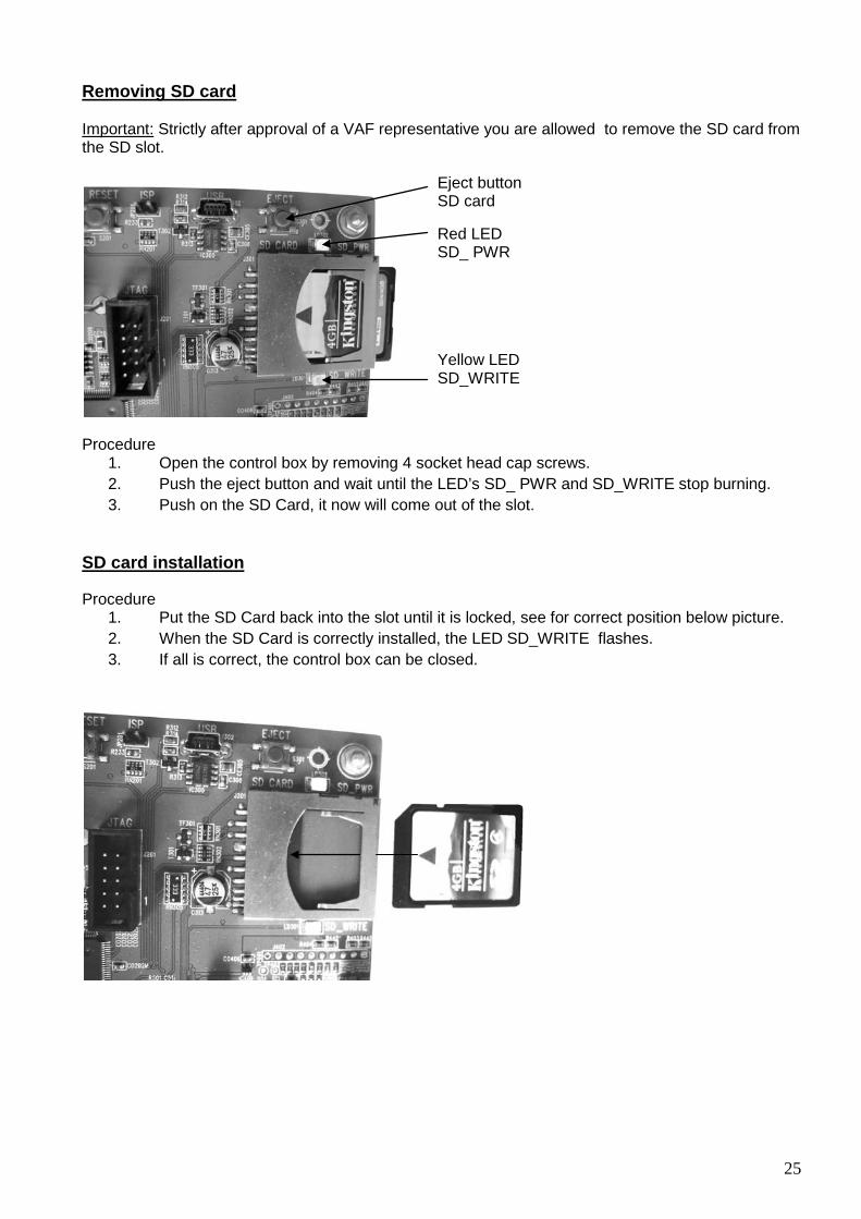
Removing SD card
Important:
Strictly after approval of a VAF representative you are allowed to remove the SD card from the SD slot.
Procedure
1. Open the control box by removing 4 socket head cap screws. 2. Push the eject button and wait until the LED’s SD_ PWR and SD_WRITE stop burning. 3. Push on the SD Card, it now will come out of the slot.
Procedure
SD card installation
1. Put the SD Card back into the slot until it is locked, see for correct position below picture. 2. When the SD Card is correctly installed, the LED SD_WRITE flashes. 3. If all is correct, the control box can be closed.
Eject button SD card
Red LED SD_ PWR
Yellow LED SD_WRITE

26
16. CERTIFICATES For a thrust and torque measuring system classification certificates are not required.

27
17. DRAWINGS

28

29
30

31

32

33
18. ABBREVIATIONS
ANSI American National Standards Institute AWG American Wire Gauge dia Diameter DIN Deutsches Institut für Normung DN Diameter Nominal EEPROM Electrically Erasable Programmable Read-Only Memory EPROM Erasable Programmable Read-Only Memory Hz Hertz (Frequency) IEC International Electrotechnical Commission IOM Installation, Operation and Maintenance JIS Japanese Industrial Standard Kg Kilograms LED Light Emitting Diode PAL Programmable Array Logic PT100 Temperature Sensor RAM Random Access Memory RH Relative Humidity VAC Volt Alternating Current ºC Degrees Centigrade Nm Newton meter

34
19. PARTS LISTS 19.1 STATOR PART
35
19.2 ROTOR PART

36
19.3 AVAILABLE SPARE PARTS FOR STATOR AND ROTOR PART When ordering, specify the part number as mentioned below, as well as serial number of the TT-Sense thrust & torque measurement system Item Part number Qty. Part name
0379-0186 (PCB incl. Alu. box)
1
Sensor PCB (Rotor)
0379-0189 (PCB incl. Alu. box)
1
Processing PCB (Rotor)
0379-0191 (PCB incl. Alu. box)
1
PSU Rotor PCB (Rotor)
0397-0358
1
Control PCB (Control box)
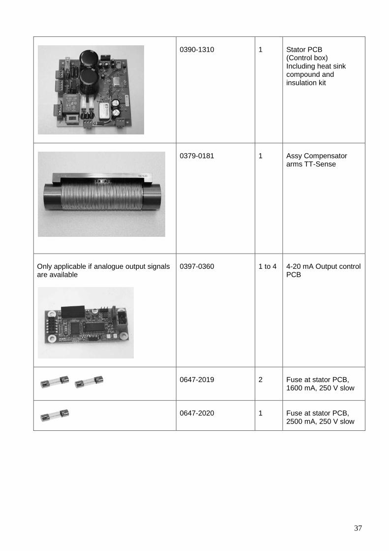
37
0390-1310
1
Stator PCB (Control box) Including heat sink compound and insulation kit
0379-0181
1
Assy Compensator arms TT-Sense
Only applicable if analogue output signals are available
0397-0360
1 to 4
4-20 mA Output control PCB
0647-2019
2
Fuse at stator PCB, 1600 mA, 250 V slow
0647-2020
1
Fuse at stator PCB, 2500 mA, 250 V slow

38
19.4 TRANSPORT/MOUNTING TOOLS Be aware that these tools should be securely stored in the spare parts box. These tools are needed when the sensor is removed and re-assembled. The mounting plate is dedicated for this specific sensor.
1
Mounting plate/ Connecting rod detector arms
6
Temporary spacer TT-Sense
19.5 INSTALLATION TOOLS
Please note that following standard tools are needed for installation: • Torque wrench (5-50 Nm) with rectangular open end fitting 17 mm • Torque ratchet spanner (2-20 Nm) with 5 mm hex bit / set of allen keys • Cir clip pliers for retaining rings
39
20. WARRANTY CONDITIONS 1. Without prejudice to the restrictions stated hereinafter, the contractor guarantees both the
soundness of the product delivered by him and the quality of the material used and/or delivered for it, insofar as this concerns faults in the product delivered which do not become apparent during inspection or transfer test, which the principal shall demonstrate to have arisen within 12 months from delivery in accordance with subarticle 1A exclusively or predominantly as a direct consequence of unsoundness of the construction used by the contractor or as a consequence of faulty finishing or the use of poor materials.
1A. The product shall be deemed to have been delivered when it is ready for inspection (if inspection at the premises of the contractor has been agreed) and otherwise when it is ready for shipment.
2. Articles 1 and 1a shall equally apply to faults which do not become apparent during inspection or transfer test which are caused exclusively or predominantly by unsound assembly/installation by the contractor. If assembly/installation is carried out by the contractor, the guarantee period intended in article 1 shall last 12 months from the day on which assembly/installation is completed by the contractor, with the understanding that in this case the guarantee period shall end not later than 18 months after delivery in accordance with the terms of subarticle 1A.
3. Defects covered by the guarantee intended under articles 1, 1a and 2 shall be remedied by the contractor by repair or replacement of the faulty component either on or off the premises of the contractor, or by shipment of a replacement component, this remaining at the discretion of the contractor. Subarticle 3A shall equally apply if repair or replacement takes place at the site where the product has been assembled/installed. All costs accruing above the single obligation described in the first sentence, such as are not restricted to shipment costs, travelling and accommodation costs or disassembly or assembly costs insofar as they are not covered by the agreement, shall be paid by the principal.
3A.If repair or replacement takes place at the site where the product has been assembled/installed, the principal shall ensure, at his own expense and risk, that:
a. the employees of the contractor shall be able to commence their work as soon as they have arrived at the erection site and continue to do so during normal working hours, and moreover, if the contractor deems it necessary, outside the normal working hours, with the proviso that the contractor informs the principal of this in good time;
b. suitable accommodation and/or all facilities required in accordance with government regulations, the agreement and common usage, shall be available for the employees of the contractor;
c. the access roads to the erection site shall be suitable for the transport required;
d. the allocated site shall be suitable for storage and assembly;
e. the necessary lockable storage sites for materials, tools and other goods shall be available;
f. the necessary and usual auxiliary workmen, auxiliary machines, auxiliary tools, materials and working materials (including process liquids, oils and greases, cleaning and other minor materials, gas, water, electricity, steam, compressed air, heating, lighting, etc.) and the measurement and testing equipment usual for in the business operations of the principal, shall be available at the correct place and at the disposal of the contractor at the correct time and without charge;
g. all necessary safety and precautionary measures shall have been taken and adhered to, and all measures shall have been taken and adhered to necessary to observe the applicable government regulations in the context of assembly/installation;
h. the products shipped shall be available at the correct site at the commencement of and during assembly.

40
4. Defects not covered by the guarantee are those which occur partially or wholly as a result of:
A. non-observance of the operation and maintenance instructions or other than foreseeable normal usage;
B. normal wear and tear;
C. assembly/installation by third parties, including the principal;
D. the application of any government regulation regarding the nature or quality of the material used;
E. materials or goods used in consultation with the principal;
F. materials or goods provided by the principal to the contractor for processing;
G. materials, goods, working methods and constructions insofar as are applied at the express instruction of the principal, and materials or goods supplied by or on behalf of the principal.
H. components obtained from third parties by the contractor insofar as that party has given no guarantee to the contractor.
5. If the principal fails to fulfil any obligation properly or on time ensuing from the agreement concluded between the principal and the contractor or any agreement connected to it, the contractor shall not be bound by any of these agreements to any guarantee regardless of how it is referred to. If, without previous written approval from the contractor, the principal commences disassembly, repair or other work on the product or allows it to be commenced, then every agreement with regard to guarantee shall be void
6. Claims regarding defects must be submitted in writing as quickly as possible and not later than 14 days after the discovery of such. All claims against the contractor regarding faults shall be void if this term is exceeded. Claims pertaining to the guarantee must be submitted within one year of the valid complaint on penalty of invalidity.
7. If the contractor replaces components/products under the terms of his guarantee obligations, the replaced components/products shall become the property of the contractor.
8. Unless otherwise agreed, a guarantee on repair or overhaul work carried out by the contractor or other services shall only be given on the correctness of the manner in which the commissioned work is carried out, this for a period of 6 months. This guarantee only covers the single obligation of the contractor to carry out the work concerned once again in the event of unsound work. In this case, subarticle 3A shall apply equally.
9. No guarantee shall be given regarded the inspection conducted, advice given and similar matters.
10.Alleged failure to comply with his guarantee commitments on the part of the contractor shall not absolve the principal from his obligations ensuing from any agreement concluded with the contractor.
11.No guarantee shall be given on products which form a part of, or on work and services on, goods older than 8 years.

VAF Instruments B.V.
Vierlinghstraat 24, 3316 EL Dordrecht, The Netherlands
P.O. Box 40, 3300 AA Dordrecht, The Netherlands
T +31 (0) 78 618 3100, F +31 (0) 78 617 7068
[email protected], www.vaf.nl
Specifications subject to change without notice.
Agents and distributors in more than 50 countries.
Represented by