t!tle - nasa
TRANSCRIPT


T!TLE A CWEM)XL?Z4 OF STATIC W I S E
DATE
DATE
DATE
DATE
NGM~ER c 160-10021-1 REV LTR
ACTIVE WEET RECORD I I 1 1
ADDED SHEETS
a C-
SHEET / SHEET J
> NUMBER WM8ER
i I I I
ADOED
Q! 8-
SHEET >
N W E R
SHEETS
SHEET
NUMBER SHEET
N W E R
. *
ii ill
iv v
vi v i i
xr i i i ix
X
xi
----.- OII: r a w nm;
- - 1
NUMBER D16U-10032-i REV LTR
ACTIVE N E E 1 RECBllt
irD0Eb SHEETS v
ADDED SHEETS
WEE T
W E R
SHEET

P 1
REvmmls LTR DEXRIPTlkUI - --=WpaouAL - 1 I
SHEET iv

LIMITAT IONS
SHEET v

DL60-10021-1 ABSTRACT
This report preasnts the results of a series of t e s t s conduc-
ted on a series of 13 foot rutors,with various blade t w i s t s
coneucted during the time pariod :ram 1969 to 1972. The tests
were accomplished under a joint NASA, ONERA and Boeing agree-
neat at AFAPL Hright: Patterson Air Force Base, Ohio and the
GNERA 8-meter tunnel at Modme, France. L - 5 t h static and
cruise performance data are presented.

The series of testa were initiated to eetabliah a data base
for rotor design o f low disc k~ading prop-rotors as applied
to tilt rotor aircraft, The report presents a coilection of
cruise data covering the fright Mach number range of - 3 to
.68 on three rotors w i t h design blade twiots of 26.6a, 3G0
and 449 . Static hover data for 36* and 4B0 t w i s t a m also
presented.
For the design twist of 3G9 both ealid niuminum blades and dy-
namically scaled conyosf-kc blcdee ware * a s t a d fs sstiiblioh the
affect of blade untwisting on huve~: and czuise ger;Ecmance.
The repost presents data for a wide range of operating conditions,
RPM, tbrrst, and f 1 ight Y%~ch numnbsr to onable the user to
astablfsh t h ~ eTfecL, o f p r ~ p s l l e r paranetera on performance

Section drag coefficient
Section lift coefficient
Thrust coefficient I I ~ ~ ~ / p n ~ ~ ~ a
Power coefficient, ~/pn% D'
Blade Chord
Rotor Diameter, feet
Spinner drag 3/2
Propeller Figure of Merit, 0.798 k- CP
Propeller Advance Ratio, ~o/nD, with n = v0cos a ,- , with a: rotor tilt anqle
%
Shaft Power, FT-LB/SEC
Spinner base pressure
Free sltream pressure
Rotor radius
r/R, local blade station radiue ratio
Reynolds numbsr
Spinner base area
Groes thrust
Free stream velocity
Velocity at blade tip
Blade oection tlaicknerr
Rotcr tilt angle
Rotor bl8da pitch angle at 314 R
v i i i

. .. , . .- b . . , -" * , -. ... r " ~. * . . - - . 4. ... ) t - : -. .+**..~,~L.,L.- & > , - . . . . .. f:; -.': .'...?;:.p",,' " . . &: -::. ~.- - I-' '#.- '4'. - . .
, * . . .: ~
. . * .. ,. - . . . - , - . , , .) * _ . :
) ..-,. . . t , . . : 4 .. ;- L - . ~. - ---- -- . ~ - .- .:.; %2 i L - - - - - . -i-.. -.-- . .- .------ - . -
i! B Incrmental blade twist angle
a Rotor solidity
P Density
n Blade effieienty at forward speed
NOTR: Although the data presented in t h i s report are in
conventional propsiler terminology, the helicopter
usage is included for the reader's convenience.
HELICOPTER ROTOR TERMINOLOGY P -
~ ? T R ~ v ~ ~ C ~ h power coefficientr
TN
Thrust coefficient, P nR2vTZ
P , dvance R a t i ~ , ~ ~ / V ~
P - . M . ~ Xover Figure of Merit, .707 % h 3 /2 -

TABLE OF CONTXNTS
INTRODUCTIOH
DISCUSSIOPU' . . ROTOR DESIGN . TEST INSTALLATIONS
DATA INDEX e . 5.1 STATIC DATA
5 . 2 CR3ISE DATA
STATIC DATA e 0
6.2 P Z R F O W C P Or D TWIST BLADES
C R U I S E D A T A e .. 7.3. PERFO-CB OF F TWIST BLADES
7.2 PERFORMANCE 8P E TWIST S W E S
7.3 BEIRFORMANCE OF D TWIST BLADES
SFERENCES e * e . a e 0
APPENDICES
A EFFECT OF DYMMIC DESXGN ON BLADE OPERATXNG TWIST . . . . . . . , . A-1

LXST OF FZGPlZES
FIGURE PAGE
3.1 BLADE CHARACTERISTICS . . 3.2
4.1 STATIC TEST INSTALLATION AFAYL TEST STAND 3 4 ' 2
4 . 2 CRUISE TEST INSTALLATION ONEYA 8-METER TUNNEL . 4 ., 2
4 . 3 AFAPL RIG 3 .INSTALLATION DETAILS s e 6 4 . 3
4 . 4 ONERA 8-METER TUNNEL INSTALLATION DETAXLs * . 4 .4
TABLE
3.1 BLADE IDENTIFICATION s 3.1

IKTRODUCTIQN
During the 1960-68 t i m e period a number of companies engaged
i n prel iminary des ign stadies of t L ? t rotcx aircraft. These
v e h i c l e s used l a r g e d%met~r/Eov disc loa.dfng: rotors w h i s h
were rotated from a horizontal plans i n hover to an axia l
position for C X U ~ S B flight. A t that time very l i t t l e data
were available to confirm the pedictei? performance of these
rotors in hover or in cruisu whara speeds up to Mach=.7 were
obtainable with. the ins ta lbed pswar diotakeit .-,. hover require- ments.
TO confirm tha rotor performance predictions and gain an in-
s i g h t i n t o the effect of key rotor des ign parameters on cruise
and hover performance, a t e s t progxam was i - i t i a t sd i n .1.9&8
involv ing NASA-Antea, the Army a\YWL,the Boeing Vexto1 Company
and ONERA of France. The program undertaken involved testing
of f i v e al-umirum 1 3 f o ~ t diamet,ex rotosa daaiyned gsr a
aange of b lade twis ts and one torsionally dynamically scaled
rotor - both s t a t i c and high s ~ e a d cruise test ing was pursu3d-
Total t w i s t was varied from 2 6 O La 4 Q 0 far the rccor d e s i g n s .
S t a t i c tests were cmducted a t the A i r Force test f a c i l i t y at
Wright-Patte~~an .WB and NASA-Amen with cruise and t r a n s i t i o n
tests completed at the NAFR-Ames 4OxCO and ONERA 8-meter w4i1d
tunnels. These tests were conducted in several test periods
s t a r t i n g in 1968 an9 ending in 1972,

9160-15021-1
This report presents the hover and cruise test results fsr
rotors wtih 26O 'Fa twist,36O =Em twist,and 4 4 " "9" twist.
The "Fb and 'Dm t w i s t blades are the extrenes of the twist
range explored w i t h tho "Em twist b e i q Lke desi~n t w i s t
selected for a tilt rotor design st'~d.1 con5 qcted by 3ot ing.

2.0 DISCUSSION
Presented i n this r epor t is a m i l e c t i o n of a l l t he da ta ob-
tained from the c ru i se and hover tests conducted over a four
year p e r h i , The da ta sec t ion is divided i n t o two major sec-
t ions , Static; Perfo=nca, Section 6 a ~ d Cruise Performance,
SectiorA 7. S t a t i c performance is suIxiiviGed t o present test
-esi;lts for I) =d E design twists while t h e c ru i se da ta presents
g r e s u l t s f o r D, E, and F twists. A l l performance coe f f i c i en t s $
presented i n t h i s document are i n conventional propel ler tern:-
1:alGJy .
A coqLe te da ta index ind ica t ins the test ranses, i n terxra iif
qerat ing condition 31=C types of 2ata ;resented is given in
Section 5 .
2.1 STATIC PZRFOPMANCE 1
1:s ! -*
S t a t i c data on the D and E twist blades is presanted on pages !FG % -.- 6.1-1 'Aru 6.2-19. A l l the ciata inclzded %as obtained during & 1972 at Wright Patterson AFB AFAPL on t e s t stand No.3. The &
Lis: sec t ion i s divided i n t o two areas , the r e s u l t s f o r the D blade ;-- -.f
k?:,. r?l',
and those f o r the E blades. Ali da ta are presented to show the
e 'act of collective angle, RPM o r kip speed on s t a t i c e f f ic iency
(Figure of H e r i t ) . A consisten", symkc?. s s t is used throughou-;: - - the s t a t i c da ta to iden t i fy +he co l l ec t ive angles t e s t e d , as
indicated on the Figures.
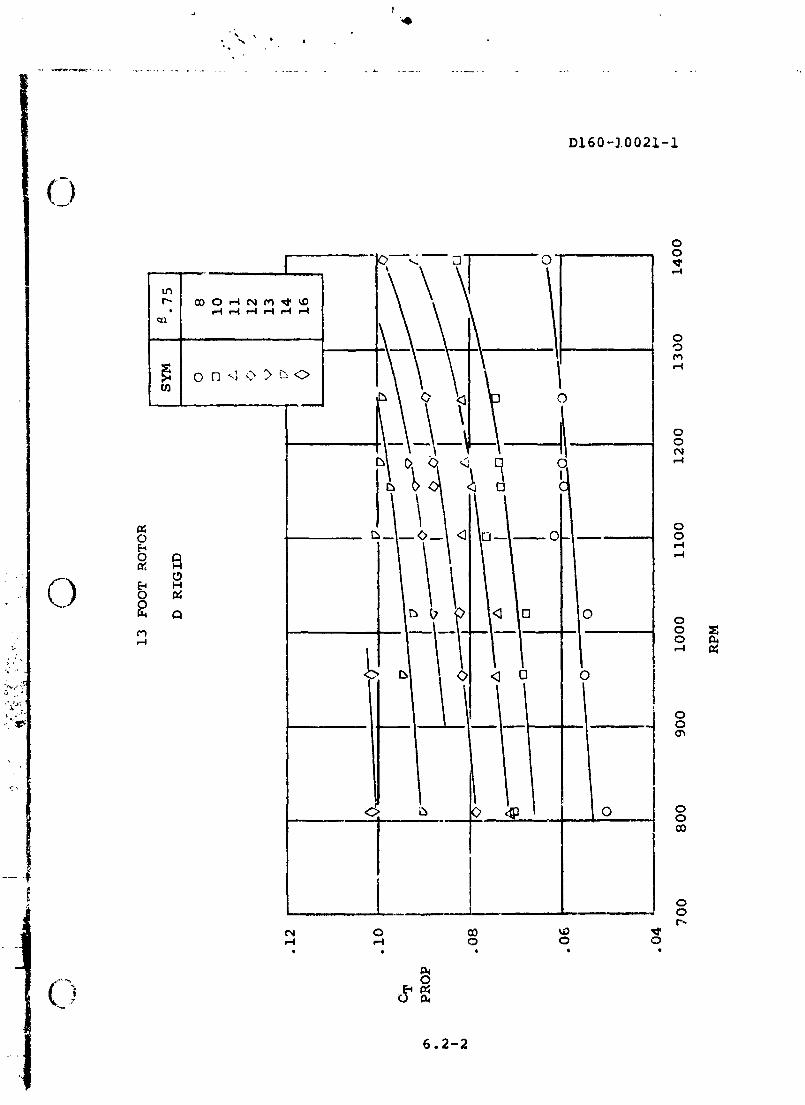
On each f igure a fa i r ed l i n e has been drawn. This f a i r i n g was 9
obtained as follows. I c i t i a l l y , a l l the test poicts were p lo t t ed
as CT and CP versus R?M. For both E and D t w i s t r i g i d ;
2.1
--- . * <. t i pg~g ; " - . , $ . > .,i - .! ,. ". . . ,-v. . . ir I - . L .-a. 2 : 3.6 - , , . , A ,-
. - - - 4 - - -

D160-10021-1
blades a fa i r ing cf t h i ~ da ta was made t o b e s t f i t the d a t a
f o r both CT md CP acd as ins these f a i r i n g s Figure of Merit
was c a l c ~ l a t d . For the E blades -cause of da ta s c a t t e r the
k a s i z tesc Latz was carpet p lo t t ed a s a funct ion of RPX and
esLleccivs a2gl.e. These p lo t s are Figures 6.1-i and
6.i-2.
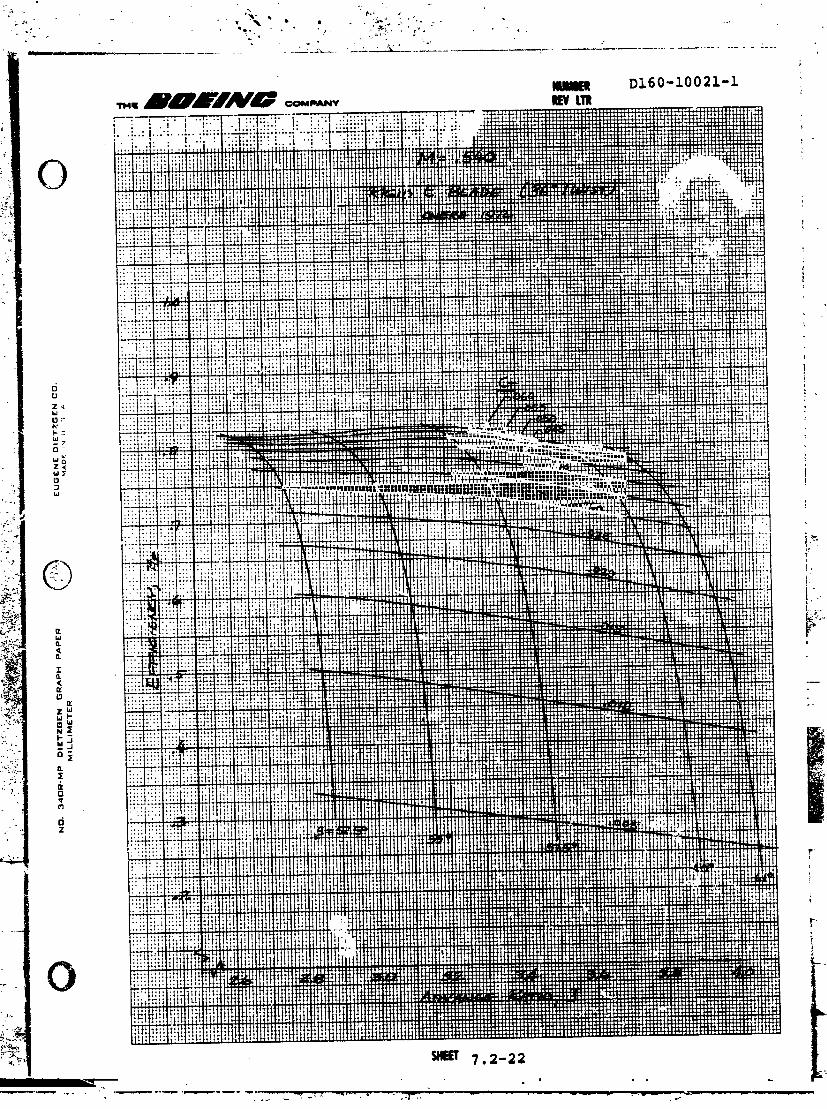
I-' .ne rzsu;.ts for the E blades are given i n Figures 6.1-1
"rcush 6-1-21. Open symbols are test da ta for the r i g i d
a3~snin~.~;. Slades while s o l i d symbls are are f o r r e s u l t s from
t h e dynamically scaled blades. The f a i r a d l i n e s on the curves
are obtained for the r i g i d blades. Consideratie da ta s c a t t e r
is seen a t low ti.;, Nach numbers and thrust b a d i r q s f o r both
the r;qid aad dynaaic blades. Phis scatter is due co low
blaiie Reynolds n-er e f fec t . ax i low t h r u s t load s ince it is
evident i n t h e r e s u l t s f o r both ro tors .
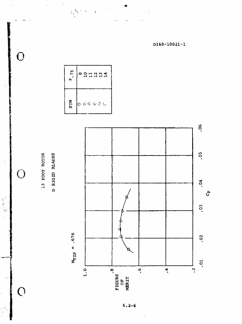
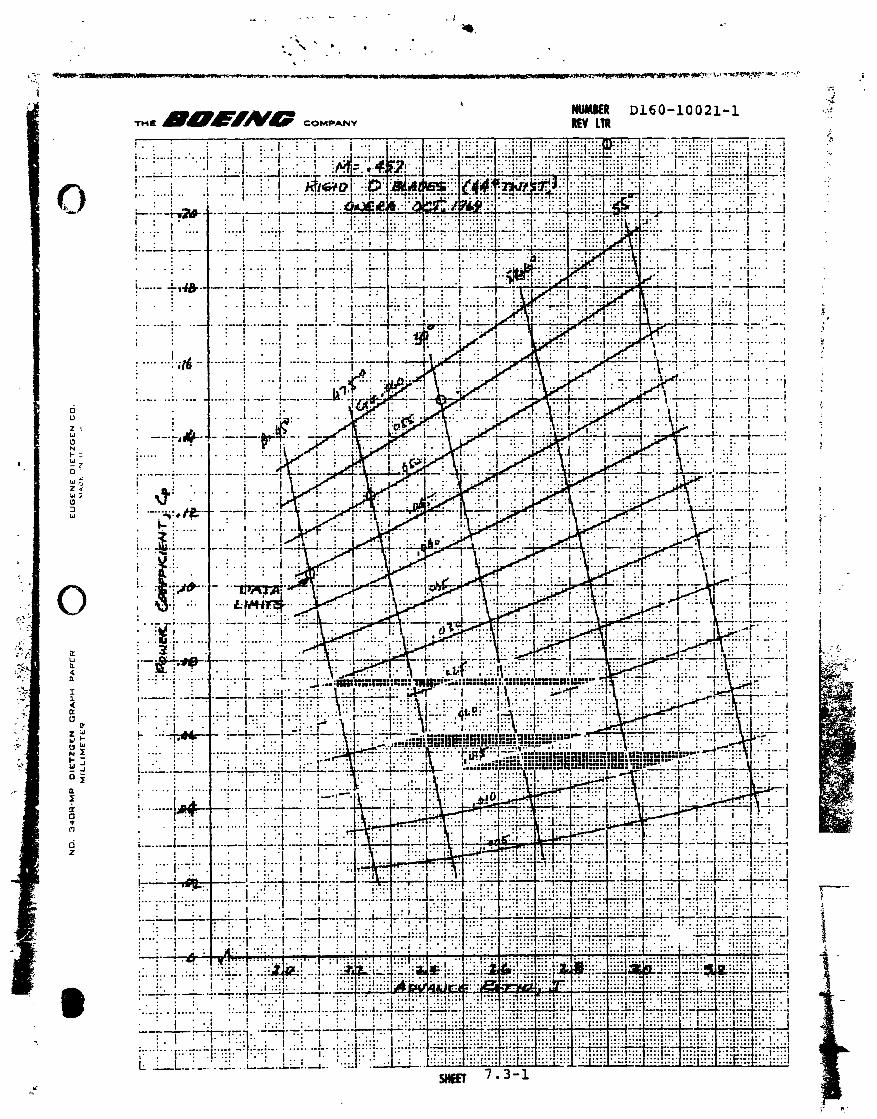
A such more cons is ten t set of data uas obtained with L e D set
of blades with l e s s da ta s c a t t e r o c c u r i n g . Bowevsr , an un-
usuzlly high Figure of M e r i t r e su l t ed at tip Mach number of
-689 (1102) RPM. A t t h i s t i p speed the power coe f f i c i en t s
shown i n Figure 6.2-1 are consisteri t with those at other RPM.
However more t h r u s t was obtained a t thia condition and Figures
of M e r i t appear to average 6 points higher than expected. This
is a t t r ibu ted t o a v ib ra t ion t h a t occurred w i t h the t e s t
f a c i l i t y which induces blade o s c i l l a t i o n and contributed
dynamic l i f t t o t h e blades without separat ion which would be

D160-i0021-1 reflected i n t h e power coafZicients . Because of this, Figur t s
6 .2 -7 anu 6.2-13 inOicate a lower Figure of Merit based on t h e
f a i r e d data of Tigures 6.2-1 mi! 6.2-2 which is recammended
when using t h e data.
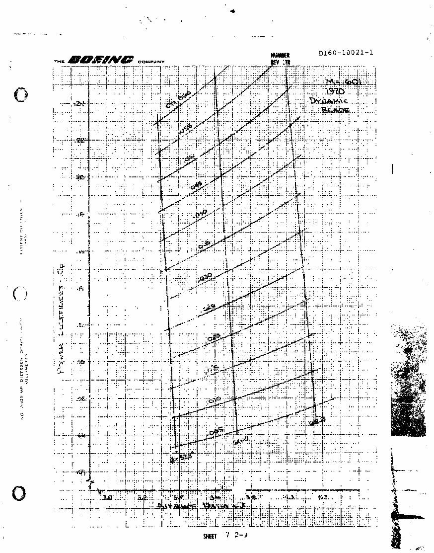
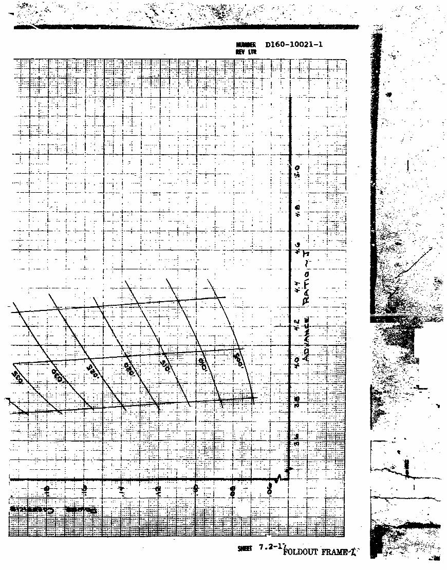
2.2 CRUISE DATA
Cruise data from tests i n the ONEP! tunne l fo r F, E, and D
t w i s t b lades are presented i n Sec t ion 7 , These r e s u l t s
w e r e obta ined i n t e s t periods i n 1369, 1970 and 1972. Data
i s presented a t each f l i g h t Mach nu-ni>er cmciit ion f o r Cp and
ri as a func t ion of advance r a t i o (J) and thrust coe2f i c i en t
(CT). T h e t e s t s were cond-acted over a Mach nurcber range from
. 3 t o .68 t o cover the cruise f l i g h t envelope capability 05
low d i s c loadifig tilt rotors.
The technique usad tc, ob ta in +&e datz was as followsz I n i -
t i a l l y , the tunnel speei wzs es t ab l i shed while the ro tox speecl
and c o l l e c t i v e angle w e r e advanced tc malatain zero thrust.
When t h e des i r ed c o l l e c t i v e angle and tucne l Mach cumber was
obtained p o w e r was increased and r o t o r RPM va r i ed while cc l -
l e c t i v e angle was maintained u n t i i m~,uimun\ t h r u s t wi th in the
blade design operati.ng envelope was achieved. Continuouo
d a t a samples were taken with both increaning aud decreasing
power RPM, a f t e r an RPM ,?ewer sweep had been conpleted t o
the next des i red s e t t i n g and the procedure repeated. Because
uf t.3e continuous d a t a sampling t e d m i q u e p r o d ~ c e d almost a
s o l i d l i n e o f test d a t a acd t o a i d i n c l a r i t y of t h e r e s a l t i n g

Gr60-1002:-i
data p l a t s a l l the test p o i n t s axe nct indicated i n the
f igures i n Section 7 . The extreves of the t e s t data are in-
dicated on the lines of constant c c l l o c t i v a dngles by circles.
Section 7 presents resules of the cruise testing as Cp a d il
versus J for constant CT a t a constant flight Mach r.u;.&er.
To create these plo t s an interpoht5.te c o q x t o r progran was
created. A l l of the test data point8 for a given Sach number
were input to the program. The program used the input data
to esJ,ablish a curve fit which i n turn was interpolated t o
cbtair. the Cp or w i t h the appropriate J for a iesired i~
level on each l i n e of c o l l e c t i v e angle.
The cruise data presented i n Section 7 is subdivided into
C,'uee subsec';ioas. Data for the P twist i n Section 7.1, for
E t w i s t i n Section 7 . 2 and D 2wist i n Section 7 . 3

A l l rotors tasted d ~ r i n g these programs were ;-bladed, w i t h a
13-foot diameter. The basic design was evolvea from a Boeing
tiit xctor study of a meilium l i f t helicopter replacement i n
the gross weight c las s of 4 0 , O C O to 5G,000 La. his required
35 foot diameter rotors t o maintain d i s c loading of 1Q PSF.
Tna 13/55 scale ratio was selected to provide a Reynolds number
which was aczeptable for s t a t i c thrust testing and a diameter
which was compatibls w i + A the CNERA tunnel.
Detail taper, thickness and twist variation of the rotor 1s a
function of percent radius are given i n Figure 3 . 1 . A n alpha-
betical d e ~ i y n ~ z t i o n scheiie was us3d tc identi£& the design
t w a s t s as given i n Table 3 . 1 . A i r f c i l , taper and t w i s t
distribrrtioi~s were not varit?d. Total rotor solidity ( o j was
TABLA 3.1 BLADE IDENTIFICATION
LESLGNATION TWIST
4 4 Aluminun; Elaces 36O Aluminum Blades
26. 6 9 Aluminun~ Blades 3 6 O Dynamically Scaled
Blades

F I G U R E 3.1 BLADE C H P ! C T E R I S T I C S

4 .0 TEST INSTALLATIONS
The s t a t i c t e s t s were performed a t WAPL Wright Patterson Air
Force Base test stand No.3. The r o t o r was f i t t e d to the test
stand on a 1 3 f oo t extension to eliminate the blockage effoct
of the stand. The i n s t a l l a t i o n i s shown i n the picture,
Figure 4 . 1 w i t h the i n s t a l l a t i o n Getails shown i n Figure
4 . 3 . The b a f f l e shown i n Figure 4 . 1 was used t o establish
dynamic character i s t i c s 05 the dynamic rotor and e s tab l i sh
the operating envelope of the E' dynanic blades . It was ra-
moved for performance t e s t i n g .
Cruise test i n s t a l l a t i o n a t tho QNELSA $-meter t unne l is shown
i n the picture, Figure 4 . 2 with t h e i n s t a l l a t i o n detaih
shown i n Figure 4 , 4 .
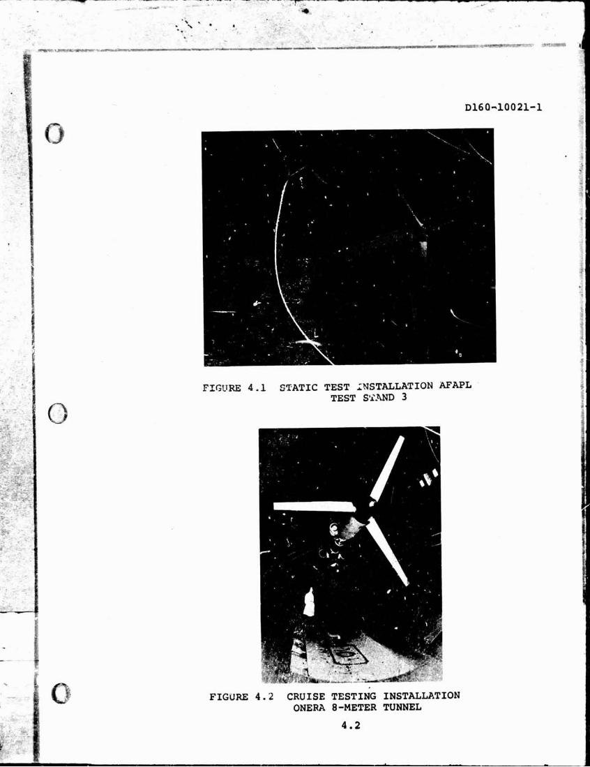

FIGURE 4.3 AFAPL RIG 3 INSTAUATION DETAILS
4 .3

. - GURE 4 .4 QNERA 8-METER TUNNEL INBTALWITION'DETAI&+S
. - . .
4.4
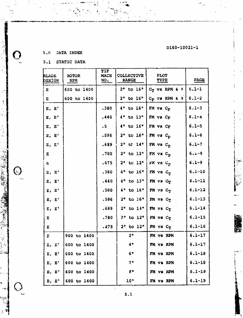
D160-10021-1 5.0 DATA INDEX
5.1 STATIC DATA
COLLECTIVE
FM vr RPM

5.1 STATIC DATA (contimed)
LnJ) E ROTOR ESIGN RPM
II_
TIP MACH NO . - COLuEC 2IVE
RANGE
FM v8 RPM
FM ve RPM
l?M vs Cp
EM va Cp
FM vs Cp
F'M VS Cp - FK vs Cp
Fx V 8 cg
mi vs Cp
Em \*a Cp
m ve Cp
FM v8 CT
FM vs CT
FM vo CT
FM YO CT
FM vs CT
BK V8 CT
FM VS CT
FM vs RPM
FM vat RPM
FW vo IIPM
PAGE -

5 . 1 S~ATIC DATA ( c~nt inue
DESIGN -- 800 to 1400
COLLECTIVE
b:" 1 ' :;$ 1 fAmj - - Em va RPM 6."-1
5.2 CRUISE DATA - lLADE lESIGN --- - F
F
F
F
F
'F
F
F -- E' DYNAMIC
E' DYNAMXC
E' DYlWIC
E ' DYNAMIC E' DYNAMIC
E' DYNAMIC
E ' DYlJWIC
E * DYNAMIC
'rum-EL MACH NO. ---
.456
-456
.578
.578
,610
610
.685
.685
307
a307
,455
0455
,578
578
600
.6GO
PAGE - --- 7.1-1
7.1-2
7. L-3
7 - ( . A-4 7-1-5
7.1-6
7.1-7
7.1-8 -- 5 .2 -1
7.2-2
7.2-3
7.2-4
7.2-5
7.2-6
7.2-7
7.2-8 --

5 .2 CRUJSE UATA (continubd) ~160-10021-1
COLLECTIVE BLADE TUNNEL RANGE DECI GN A C H NO. DEG
1972
E' DYNAMIC
E' DYNNGC
E' DYNAMIC
E' DYNAMIC
E' DYNA!!IC
50. to 5Sn
so0 to 5s0
52.S0 t o 61°
52.S0 to 61'
SO0 t o 62, 5O
SO0 to 62. 5O
57.S0 to 1i4.O0
57.!i0 t o 64.0°
5S0 ti, r5.6O
5 S 0 t; 65.7'

5 . 2 CRUISE DETA (cont inued) ~ i 6 0 - 1 0 0 2 1 - 1 -----
)LADE )ES IGN
TUNNEL MACH NO.
0457
0457
.578
. 5 7 8
, 5 8 2
.582
.609
.609
. 6 8 1
- 6 8 1
1
4 s 0 to 5 s 0
4 5 = to 5 s 0
57.6O and 60°
57.6O and 6 0 P
SO0 to 60°
5Q0 to 60°
SO0 to 62.6'
50° to 62.6O
57.S0 to 67.7O
57 .S0 to 67.7O
PAGE - 7 .3 -1
7 .3 -2
7 .3-3
7 .3 -4
7 .3 -5
7 .3-6
7 .3-7
7 .3-8
7 .3 -9
7 .3-1(

6.0 STATIC DATA
6.1 E BLADE STATIC DATA


.8
FIGURE
Q,
OF
r
I MERIT
W
-6
13 FOOT ROTOR
E
RIG
ID B
LA
DE
S
OPEN SYMBOLS - A
LUMINUM BWES
SOLID SYMBOLS - D
YNAMICALLY SCALW


13 FOOT ROTOR
E RIGID BLADES
F X
GU
RE
OF
ME
RIT


3 B 3 h H ""I Er


6 . 2 D BLADE STATIC DATA


.8
FIGURE
0\
OF
MERIT
h) I w
.6
13
FO
OT
R
OT
OR
D
RIG
ID ELADES
SY
M
', .* u
. . C
'7
3
75
8
10
11
L 2
13
14


g * , ""I k

d d .
0 r-!
Q\ 0
(0 0 .
r 0 .
\D 0
u I 0 .
f 0
v


7.0 CRUISE DATA.
7.1 E B m E CRUISE DATA

NUMBER D160-10021-1 REV LTR


. . . , . . . . . .................. : -".:..'--+iL--": .;: ..: ' -.:: 4 ... ----- : : . . : . I i -.----- . . , . a +---.-+.. . . ! . .. . : .
. .... ... . . . ....... .... . . . . .... : .: :.. :.a&.:.. . . . .:.. .: +I.; . . . . . . i , . . . . zkr..i : : : : ; . . . . . . . . i. i.:3.f$.. . . . . . . . i ' . . . . . . . a : : ':. . . , ..... :_. ... .... ... ;..-;--.,.: -.-- :--;-- .... .-. .. - : . . . . . . . . . . . ! . n . . . . . . . . . . . . . . . . : . . . . " . ' . : ' .. ! : ' . I . .
I . . . . . . . . . . . . i ::.:.!: . . : . . : h i : : . . . . . . . . . . . . : : . , . .................. ....... .. ........ ......... . . . - . . . . . . . . . . . . . . . . . . . i :.. .,.... i.: :,, ...:... :... ... . . . . I . . .a . ..-.--.-. :.I...., ...: E:&-::.:. . . . . . . . . . .-.-,- I . I . . . ,
! : : . , , . , : . . . .. . ... . . . - . .. . . . : I . !. .,;: ., A: ,::. 1. .;::.: .. !'. 1' :.. ::.:.: .i::::,;;.:: ': # . ! :--.1. -. J- .: .. I ............. I.. . ...- :..'ZA.::.:..!-!. '.I. 1
, . . . I.. . : I .. .- ...-- - . . . .....- - --- - - - -- -... .--- -.-. ..---.. . -


7.2 E BLADES CRUISE DATA


. , ,. . ...... ........ . ...... .... . . . . : , .b 1 :-..-. .. i 1. ......I... .: ...--.. 1 i :. . . . . . . k , I. . I , j . ! . '
. . a . 4 < .
. . .... . . I : : /.1 / / . I:.::. . I ; s . ! ! . i


WUC#CII Di60-10021-1 7-a me%ZV!iAli coumnv --------- -- r-,- : , , , , , 77-7.77---ry.-- --- ReC' LL
. . . . . . . . 1- - - : - - ~ T T : 7 ! 7 - ; ~ F ~ - - ; : - ~ \-:-17-1-' -:-.--1.-.: ' . I . . . ! . I . . . . . . .. . . . . . . . . . . . . . . . . . . . . . . . ..:. ..I . . . . : .i. : . . . . . . I .
! . . . . . . . . . . : i . i, 1 1 : i : : : : : , ,. j: , , I : L,. , . ! , ; f i i : : . ! : , : I i :. .--1.-- -- . - . . . t--4 1 . 1 r,. i
j . . . . . . . . . . ...................... 1 . . I . , . . . . . . . : :.
- a . . .-.. . . . . . . . . . . . . . . ._ .... ..___.._ ..-. ...--- I . , . . . . . . . . I . . . . . . . . . . . .....-.. ; i. ............ . ... . . . . . . . . . . .
; ; ..... . .... ... : ....... , ; t . . . . . .
. . .
SWT 7.2-12


I ! ' . . I.. .: .. i .; . 1 ... . . ' . . ; . - . . . . , - . . . I . . . - 3 . . . . :,.21-L I... ..-.. : - . . -


a . - - . . . . ,.-..-. =.. --,. ---. -
REPRODUCIBILITY OF THE QRlGlNAL PAGE IS POOR. --%>


7.3 D BLADE CRUISE DATA
4
NUMBER D160-10021-1 REV L l R

NUM#R D160-10021-1 THE ~~~/~~ COMPANY REV Ln
. . . . ........... .. . . . . . . . . . . . . . -.- ........ _ _ .-... .- ..-. .-- I . I i :I-: . .


8.0 REFERENCES
BOEING DOCUMEN'JS
Investigation of the Performance of Low Disc
Loading Tilt Rotors in Hovering and Cruise
Flights - Volume I Analysis and Results
Volume 2 - Wind Tunnel Program Details
Pitch-Lag Flap Stability Test and Analytical
Sensitivity Studies
Test Procedures for a Hover Performance Test
on Rigid and Dynamically Scaled Rotor Perform-
ance Models
Test Procedures for a Cruise Performance Test
on Rigid and Dynamic Rotor Performance Models
ONERA Document NASA-ONERA Tests of Two 13/55 Scale 1/1832 SN-Fasc. l/2
Tilt Rotor Propellers in the SIMA Tunnel
AGARD Paper A Summary of Wind-Tunnel Research on Tilt September 1972
Rotors from Hover to Cruise Flight, W.L. Cook,
NASA and PaPoisson-Quinton, ONERA

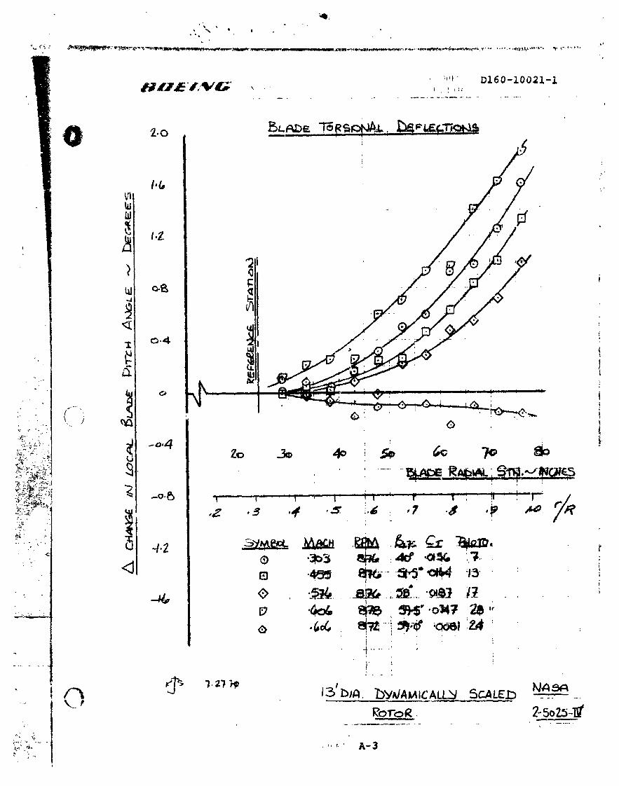
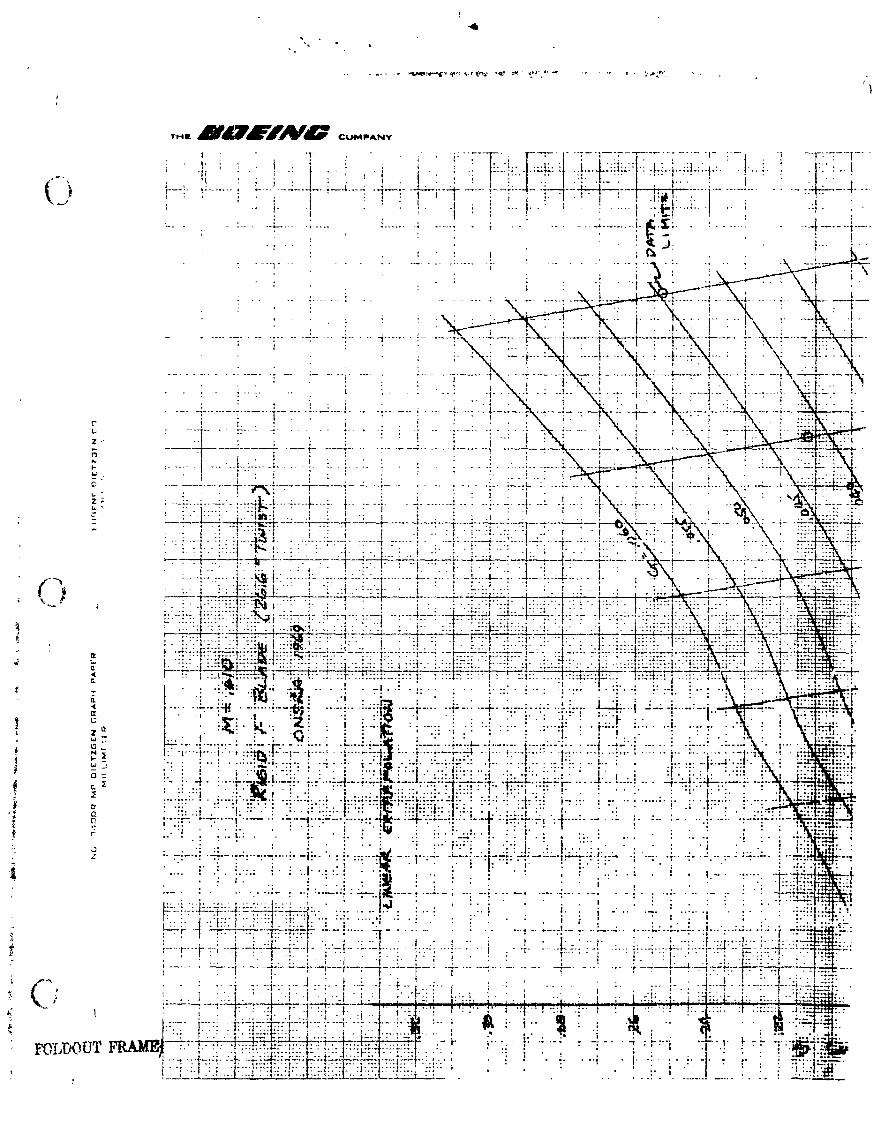
WPENDSX A EFFECT OF DYNAMIC DESIGN ON BLADE OPERATING TWIST

01 60-1 0021 -1
During the 1970 tests a t ONERA photographic techniques were used t o
establ ish the e f f ec t o f th rus t loading on rad ia l tw is t o f the blades under
operating conditions. The methods used t o establ ish the change i n t w i s t
o f the E dynamic blades are described i n 0160-10013-1 and -2 and an AGARD
paper by Mr. W. 1. Cook and Mr . P. Poisson-Quinton, (The Aerodynanics o f
Rotary Wings, Marsef 11 e, France, September 1972).
Pages A-3 and A-4 are resu l t s o f the tes ts using the photographic techniques.
Page A-3 shows the rad ia l va r ia t ion o f t w i s t increasing as thrust and f l i g h t
speed increases while Page A-4 indicates the e f f e c t o f increased thrust on + a
rad ia l t w i s t a t a given f l i g h t condition.