tube and pipe tube data metric sizes e 5 - … · tube and pipe merchants within australia offer a...
TRANSCRIPT
This page is part of a complete catalogue containing technical and safety data.All data must be reviewed when selecting a product.
Pirtek reserve the right to change technical specifications without notice E
TUBE
AN
D PIPE
IND
EX
1Rev. 0
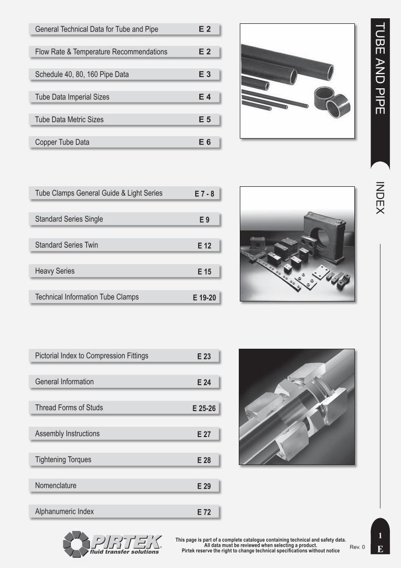
General Technical Data for Tube and Pipe E 2
Flow Rate & Temperature Recommendations E 2
Schedule 40, 80, 160 Pipe Data E 3
Tube Data Imperial Sizes E 4
Tube Data Metric Sizes E 5
Copper Tube Data E 6
Tube Clamps General Guide & Light Series E 7 - 8
Standard Series Single E 9
Standard Series Twin E 12
Heavy Series E 15
Technical Information Tube Clamps E 19-20
Pictorial Index to Compression Fittings E 23
General Information E 24
Thread Forms of Studs E 25-26
Assembly Instructions E 27
Tightening Torques E 28
Nomenclature E 29
Alphanumeric Index E 72
This page is part of a complete catalogue containing technical and safety data.All data must be reviewed when selecting a product.
Pirtek reserve the right to change technical specifications without noticeE
TUBE
AN
D PIPE
TECH
NIC
AL D
ATA
2Rev. 0
INTRODUCTION
Tube and pipe merchants within Australia offer a range of products suited to hydraulic, pneumatic and instrumentation applications. The data included here is intended as a guide only to the products more commonly used, and should not be construed as representative of products offered for sale by Pirtek. Specifications and technical data are typical.
Imperial Tube and Pipe
Tabulated burst pressures for imperial tube and pipe size of various sizes are derived from use of Barlow’s Formula. Results are converted to bars for convenience.
BP = Wall Thickness x 2 x Tensile Strength / Outside Dia. (kg/cm² ) (cm) (kg/cm²) (cm).
Material Adopted tensile strength Tabulated
Butt welded wrought steel pipe *(Sched. 40, 80, 160)
275 MPa (2812 kg/cm²) Yes
Lap welded wrought steel pipe
345 MPa (3515 kg/cm²)
No. Add 20% to above.
Hydraulic Cold Drawn Steel Tube (CDS)
345 MPa (3515 kg/cm²) Yes
Stainless Steel302, 303, 304,309,310, 316, 321, 416
510 MPa (273 kg/cm²) Yes
Stainless Steel410, 430
414 MPa (4222 kg/cm²) No
Stainless Steel202, 440C
690 MPa (7037 kg/cm²) No
Copper 220 MPa (2 250 kg/cm²) No
* Wrought iron pipeThicker than wrought steel. Adopt the same burst pressure as butt welded wrought steel.
Metric Tube
Metric steel tubing is designated by the combination of outside diameter and wall thickness. Pirtek recommends the use of precision cold drawn seamless tube manufactured to conform to the requirements of DIN 2391 Part 1. Material grade should be St 37.4, Type NBK, as described in DIN 1630. Maximum exterior hardness 75 HRB.Tabulated pressure ratings are in accordance with :
DIN 2413-I (static loads using a tensile stress yield point of 235 N/mm²)DIN 2413-III (dynamic loads using a yield point of 226 N/mm²).
For thick walled tube (ie the ratio of OD to ID exceeds 1.35), the tabulated pressure is as per DIN2413-III, but with the 235 N/mm² yield point. The applicable safety factor in all cases is 1.5.Allowance factors are:4 mm tube C = 0.86-8 mm tube C = 0.858mm tube and larger C = 0.9No additional provision for corrosion is incorporated.
1.4571 stainless steel tubing is designated by the combination of outside diameter and wall thickness. It should be cold drawn precision seamless tube manufactured in accordance with the provisions of DIN 17458-X6CrNiMoTi17122-m or ASTM A269. Maximum exterior hardness 85 HRB. Tolerances as per DIN/EN/ISO 1127.Tabulated pressure ratings are in accordance with DIN 2413-I (static loads using a tensile stress yield point of 245 N/mm²).Pressure ratings for dynamic loads use a yield point of 190 N/mm². Note that no yield stress is published for DIN 17458, so this is a recommended guide only. Calculations are as per DIN 2423-III for dynamic loads.
For thick walled tube (ratio of OD to ID exceeds 1.35), the tabulated pressure is as per DIN2413-III, but with a 245 N/mm² yield point. The applicable safety factor in all cases is 1.5.Allowance factors are:C = 0.9No additional provision for corrosion is incorporated.
Working TemperatureCarbon steel:Use safely with no reduction in the range of -60º to +120º C. Maximum allowable working temperature 250º C.Stainless steel:Use stated working pressures within the range -60º to +20º CMaximum allowable working temperature 400º C.Reduce pressures as indicated for the range 20º to 400º C50º C 4.5%100º C 11%200º C 20%300º C 29%400º C 33%
Tube LengthImperial tube 6.1 metresMetric tube 6 metres
Bending TubeUse the guide:
Bend Radius ≥ 3 x Tube ODBending can cause wall thinning, with a consequent reduction in safe working pressure.
Flow Rate / VelocityFlow rates given in the tables are based on the following guides:Suction lines: 0.6 - 1.2 m/sec Return lines: 3 - 4.5 m/secMedium Pressure (35 - 140 bar) lines: 4.5 - 6 m/secHigh Pressure lines (≥ 200 bar): ≤ 9 m/sec
Safety FactorIt’s recommended that hydraulic systems subjected to shock loads incorporate a 6:1 factor of safety. Use of a lower factor can be contemplated after due consideration of the system operating parameters.
Quoted working pressures for metric tubing are as per relevant DIN standards.
Copper TubeConsult page E 8
This page is part of a complete catalogue containing technical and safety data.All data must be reviewed when selecting a product.
Pirtek reserve the right to change technical specifications without notice E
TUBE
AN
D PIPE
TECH
NIC
AL D
ATA
3Rev. 0
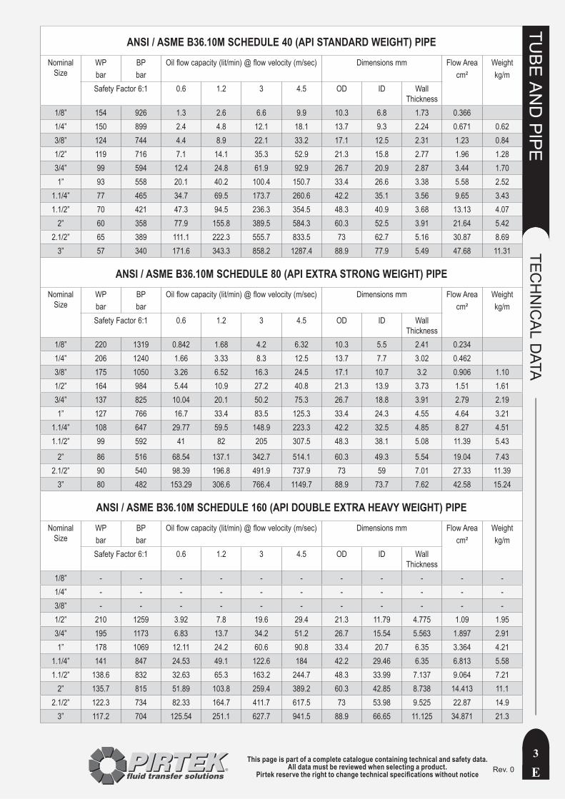
ANSI / ASME B36.10M SCHEDULE 40 (API STANDARD WEIGHT) PIPENominal
Size WPbar
BPbar
Oil flow capacity (lit/min) @ flow velocity (m/sec) Dimensions mm Flow Areacm²
Weightkg/m
Safety Factor 6:1 0.6 1.2 3 4.5 OD ID Wall Thickness
1/8” 154 926 1.3 2.6 6.6 9.9 10.3 6.8 1.73 0.3661/4” 150 899 2.4 4.8 12.1 18.1 13.7 9.3 2.24 0.671 0.623/8” 124 744 4.4 8.9 22.1 33.2 17.1 12.5 2.31 1.23 0.841/2” 119 716 7.1 14.1 35.3 52.9 21.3 15.8 2.77 1.96 1.283/4” 99 594 12.4 24.8 61.9 92.9 26.7 20.9 2.87 3.44 1.701” 93 558 20.1 40.2 100.4 150.7 33.4 26.6 3.38 5.58 2.52
1.1/4” 77 465 34.7 69.5 173.7 260.6 42.2 35.1 3.56 9.65 3.431.1/2” 70 421 47.3 94.5 236.3 354.5 48.3 40.9 3.68 13.13 4.07
2” 60 358 77.9 155.8 389.5 584.3 60.3 52.5 3.91 21.64 5.422.1/2” 65 389 111.1 222.3 555.7 833.5 73 62.7 5.16 30.87 8.69
3” 57 340 171.6 343.3 858.2 1287.4 88.9 77.9 5.49 47.68 11.31
ANSI / ASME B36.10M SCHEDULE 80 (API EXTRA STRONG WEIGHT) PIPENominal
Size WPbar
BPbar
Oil flow capacity (lit/min) @ flow velocity (m/sec) Dimensions mm Flow Areacm²
Weightkg/m
Safety Factor 6:1 0.6 1.2 3 4.5 OD ID Wall Thickness
1/8” 220 1319 0.842 1.68 4.2 6.32 10.3 5.5 2.41 0.2341/4” 206 1240 1.66 3.33 8.3 12.5 13.7 7.7 3.02 0.4623/8” 175 1050 3.26 6.52 16.3 24.5 17.1 10.7 3.2 0.906 1.101/2” 164 984 5.44 10.9 27.2 40.8 21.3 13.9 3.73 1.51 1.613/4” 137 825 10.04 20.1 50.2 75.3 26.7 18.8 3.91 2.79 2.191” 127 766 16.7 33.4 83.5 125.3 33.4 24.3 4.55 4.64 3.21
1.1/4” 108 647 29.77 59.5 148.9 223.3 42.2 32.5 4.85 8.27 4.511.1/2” 99 592 41 82 205 307.5 48.3 38.1 5.08 11.39 5.43
2” 86 516 68.54 137.1 342.7 514.1 60.3 49.3 5.54 19.04 7.432.1/2” 90 540 98.39 196.8 491.9 737.9 73 59 7.01 27.33 11.39
3” 80 482 153.29 306.6 766.4 1149.7 88.9 73.7 7.62 42.58 15.24
ANSI / ASME B36.10M SCHEDULE 160 (API DOUBLE EXTRA HEAVY WEIGHT) PIPENominal
Size WPbar
BPbar
Oil flow capacity (lit/min) @ flow velocity (m/sec) Dimensions mm Flow Areacm²
Weightkg/m
Safety Factor 6:1 0.6 1.2 3 4.5 OD ID Wall Thickness
1/8” - - - - - - - - - - -1/4” - - - - - - - - - - -3/8” - - - - - - - - - - -1/2” 210 1259 3.92 7.8 19.6 29.4 21.3 11.79 4.775 1.09 1.953/4” 195 1173 6.83 13.7 34.2 51.2 26.7 15.54 5.563 1.897 2.911” 178 1069 12.11 24.2 60.6 90.8 33.4 20.7 6.35 3.364 4.21
1.1/4” 141 847 24.53 49.1 122.6 184 42.2 29.46 6.35 6.813 5.581.1/2” 138.6 832 32.63 65.3 163.2 244.7 48.3 33.99 7.137 9.064 7.21
2” 135.7 815 51.89 103.8 259.4 389.2 60.3 42.85 8.738 14.413 11.12.1/2” 122.3 734 82.33 164.7 411.7 617.5 73 53.98 9.525 22.87 14.9
3” 117.2 704 125.54 251.1 627.7 941.5 88.9 66.65 11.125 34.871 21.3
This page is part of a complete catalogue containing technical and safety data.All data must be reviewed when selecting a product.
Pirtek reserve the right to change technical specifications without noticeE
TUBE
AN
D PIPE
TECH
NIC
AL D
ATA
4Rev. 0
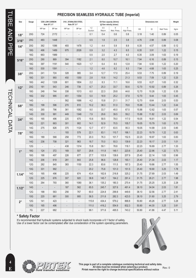
PRECISION SEAMLESS HYDRAULIC TUBE (Imperial)Size Gauge CDS LOW CARBON
Note SF 3:1*316 L STAINLESS STEEL
Note SF 3:1*Oil flow capacity (lit/min) @ flow velocity (m/sec)
Dimensions mm Weight
WP bar BP bar WP bar BP bar 1.2Suction
4.5Return
6Med. Press.
9High Press. OD ID Wall Thick. Kg/m
1/8” 20G 724 2172 - - 0.1 0.4 0.6 0.8 3.18 1.40 0.89 0.05
3/16” 20G 483 1448 - - 0.5 1.9 2.5 3.8 4.76 2.98 0.89 0.08
1/4” 20G 362 1086 493 1478 1.2 4.4 5.9 8.9 6.35 4.57 0.89 0.1218G 496 1489 675 2026 0.9 3.2 4.3 6.5 6.35 3.91 1.22 0.1516G 663 1989 - - 0.5 2.0 2.7 4.0 6.35 3.09 1.63 0.19
5/16” 20G 290 869 394 1182 2.1 8.0 10.7 16.1 7.94 6.16 0.89 0.1518G 397 1191 540 1620 1.7 6.4 8.5 12.8 7.94 5.50 1.22 0.2016G 530 1591 - - 1.2 4.6 6.2 9.3 7.94 4.68 1.63 0.25
3/8” 20G 241 724 328 985 3.4 12.7 17.0 25.4 9.53 7.75 0.89 0.1918G 331 993 450 1350 2.8 10.6 14.2 21.3 9.53 7.09 1.22 0.2516G 442 1326 601 1804 2.2 8.3 11.1 16.6 9.53 6.27 1.63 0.32
1/2” 20G 181 543 246 739 6.7 25.3 33.7 50.6 12.70 10.92 0.89 0.2618G 248 744 338 1013 6.0 22.3 29.8 44.6 12.70 10.26 1.22 0.3516G 332 995 451 1354 5.0 18.9 25.2 37.8 12.70 9.44 1.63 0.4514G - - 562 1686 4.2 15.8 21.1 31.7 12.70 8.64 2.03 0.53
5/8” 18G 199 596 270 810 10.2 38.3 51.0 76.6 15.88 13.44 1.22 0.4416G 265 796 361 1082 9.0 33.7 45.0 67.5 15.88 12.62 1.63 0.5714G 330 991 449 1348 7.9 29.6 39.5 59.2 15.88 11.82 2.03 0.69
3/4” 18G 165 496 225 675 15.6 58.5 78.0 117.0 19.05 16.61 1.22 0.5416G 221 663 301 902 14.1 52.9 70.5 105.7 19.05 15.79 1.63 0.7014G 275 826 375 1124 12.7 47.7 63.5 95.3 19.05 14.99 2.03 0.85
7/8” 18G - - 193 579 22.1 83.1 110.7 166.1 22.23 19.79 1.22 0.6316G 189 568 258 773 20.3 76.3 101.7 152.5 22.23 18.97 1.63 0.8314G 236 708 321 963 18.7 70.0 93.3 139.9 22.23 18.17 2.03 1.0112G - - 438 1314 15.8 59.1 78.8 118.1 22.23 16.69 2.77 1.33
1” 18G 124 372 169 507 29.8 111.8 149.1 223.6 25.40 22.96 1.22 0.7316G 166 497 226 677 27.7 103.9 138.6 207.9 25.40 22.14 1.63 0.9614G 206 619 281 843 25.8 96.6 128.8 193.1 25.40 21.34 2.03 1.1712G 282 845 383 1150 22.3 83.6 111.5 167.3 25.40 19.86 2.77 1.5510G 331 992 - - 20.2 75.8 101.0 151.5 25.40 18.90 3.25 1.78
1.1/4” 14G 165 496 225 674 43.4 162.6 216.8 325.2 31.75 27.69 2.03 1.4912G 225 676 307 920 38.8 145.7 194.2 291.4 31.75 26.21 2.77 1.9810G 264 793 360 1080 36.1 135.2 180.3 270.4 31.75 25.25 3.25 2.28
1.1/2” 14G - - 187 562 65.5 245.7 327.6 491.4 38.10 34.04 2.03 1.8112G 188 563 256 767 60.0 224.8 299.8 449.6 38.10 32.56 2.77 2.4110G 220 661 300 900 56.5 211.8 282.3 423.5 38.10 31.60 3.25 2.79
2” 12G 141 423 - - 115.8 434.4 579.2 868.8 50.80 45.26 2.77 3.2810G 165 496 - - 111.0 416.2 554.9 832.3 50.80 44.30 3.25 3.817G 227 682 - - 99.1 371.6 495.5 743.2 50.80 41.86 4.47 5.11
* Safety FactorIt’s recommended that hydraulic systems subjected to shock loads incorporate a 6:1 factor of safety. Use of a lower factor can be contemplated after due consideration of the system operating parameters.

This page is part of a complete catalogue containing technical and safety data.All data must be reviewed when selecting a product.
Pirtek reserve the right to change technical specifications without notice E
TUBE
AN
D PIPE
TECH
NIC
AL D
ATA
5Rev. 0
PRECISION SEAMLESS HYDRAULIC STEEL TUBE (Metric)Ø Tube Tolerance Working Pressure (bar)
St. 37.4 Carbon steelWorking Pressure (bar)1.4571 Stainless steel
Oil flow capacity (lit/min) @ flow velocity (m/sec) Dimensions (mm) Weight †
pref.sizemm mm Static
DIN2413-IDynamic
DIN2413-IIIStatic
DIN2413-IDynamic(Guide)
1.2Suction
4.5Return
6Med. Press.
9High Press. OD ID Wall Thick. Kg/m
4 ± 0.1 409 467 426 358 0.4 1.3 1.8 2.7 4 2.5 0.75 0.060 †522 502 544 422 0.2 0.8 1.1 1.7 4 2 1 0.074
6 ± 0.1 389 374 406 314 0.9 3.4 4.5 6.8 6 4 1 0.123 †549 528 572 444 0.5 1.9 2.5 3.8 6 3 1.5 0.166692 665 721 559 0.2 0.8 1.1 1.7 6 2 2 0.197
8 ± 0.1 333 289 347 243 2.0 7.6 10.2 15.3 8 6 1 0.173 †431 441 449 371 1.4 5.3 7.1 10.6 8 5 1.5 0.240 †549 528 572 444 0.9 3.4 4.5 6.8 8 4 2 0.296658 632 686 561 0.5 1.9 2.5 3.8 8 3 2.5 0.339
10 ± 0.1 282 249 294 209 3.6 13.6 18.1 27.1 10 8 1 0.222 †373 358 389 301 2.8 10.4 13.9 20.8 10 7 1.5 0.314 †478 460 498 387 2.0 7.6 10.2 15.3 10 6 2 0.395576 553 601 465 1.4 5.3 7.1 10.6 10 5 2.5 0.462666 641 694 539 0.9 3.4 4.5 6.8 10 4 3 0.518
12 ± 0.08 235 210 245 176 5.7 21.2 28.3 42.4 12 10 1 ª 0.271 †353 305 368 256 4.6 17.2 22.9 34.4 12 9 1.5 0.388 †409 393 426 330 3.6 13.6 18.1 27.1 12 8 2 0.493 †495 476 516 400 2.8 10.4 13.9 20.8 12 7 2.5 0.586576 553 601 465 2.0 7.6 10.2 15.3 12 6 3 0.666651 627 679 527 1.4 5.3 7.1 10.6 12 5 3.5 0.734
14 ± 0.08 302 265 315 223 6.8 25.7 34.2 51.3 14 11 1.5 0.462403 343 420 288 5.7 21.2 28.3 42.4 14 10 2 0.592 †434 417 452 351 4.6 17.2 22.9 34.4 14 9 2.5 0.709507 487 529 409 3.6 13.6 18.1 27.1 14 8 3 0.814576 553 601 465 2.8 10.4 13.9 20.8 14 7 3.5 0.906
15 ± 0.08 188 171 196 143 9.6 35.8 47.8 71.7 15 13 1 0.345282 249 294 209 8.1 30.5 40.7 61.1 15 12 1.5 0.499 †376 323 392 272 6.8 25.7 34.2 51.3 15 11 2 0.641478 460 498 387 4.6 17.2 22.9 34.4 15 9 3 0.888
16 ± 0.08 264 234 275 196 9.6 35.8 47.8 71.7 16 13 1.5 0.536 †353 305 368 256 8.1 30.5 40.7 61.1 16 12 2 0.691 †386 372 402 312 6.8 25.7 34.2 51.3 16 11 2.5 0.832 †452 435 471 365 5.7 21.2 28.3 42.4 16 10 3 0.962
18 ± 0.08 157 143 130 - 14.5 54.3 72.4 108.6 18 16 1 ª 0.419235 210 245 177 12.7 47.7 63.6 95.4 18 15 1.5 ª 0.610 †313 274 326 230 11.1 41.6 55.4 83.1 18 14 2 0.789 †392 335 409 282 9.6 35.8 47.8 71.7 18 13 2.5 0.956409 393 426 330 8.1 30.5 40.7 61.1 18 12 3 1.110
20 ± 0.08 212 191 - - 16.3 61.3 81.7 122.6 20 17 1.5 0.684282 249 294 209 14.5 54.3 72.4 108.6 20 16 2 0.888 †353 305 368 256 12.7 47.7 63.6 95.4 20 15 2.5 1.079 †373 358 389 301 11.1 41.6 55.4 83.1 20 14 3 1.258426 410 444 344 9.6 35.8 47.8 71.7 20 13 3.5 1.424478 460 498 387 8.1 30.5 40.7 61.1 20 12 4 1.578
22 ± 0.08 192 174 200 146 20.4 76.6 102.1 153.1 22 19 1.5 ª 0.758256 228 267 192 18.3 68.7 91.6 137.4 22 18 2 ª 0.986 †320 280 334 235 16.3 61.3 81.7 122.6 22 17 2.5 1.202385 329 401 276 14.5 54.3 72.4 108.6 22 16 3 1.406 †385 329 - - 11.1 41.6 55.4 83.1 22 14 4 1.776
25 ± 0.08 95 - - - 22.6 84.8 113.1 169.7 22 20 1 ª 0.518226 202 236 170 24.9 93.5 124.7 187.0 25 21 2 ª 1.134 †282 249 294 209 22.6 84.8 113.1 169.7 25 20 2.5 1.387 †338 294 352 247 20.4 76.6 102.1 153.1 25 19 3 1.628 †394 379 411 318 16.3 61.3 81.7 122.6 25 17 4 2.072 †437 420 456 353 14.5 54.3 72.4 108.6 25 16 4.5 2.275
28 ± 0.08 151 139 158 117 35.3 132.5 176.7 265.1 28 25 1.5 ª 0.980201 182 210 153 32.6 122.1 162.9 244.3 28 24 2 ª 1.282 †252 224 263 188 29.9 112.2 149.6 224.4 28 23 2.5 1.572302 265 315 223 27.4 102.6 136.9 205.3 28 22 3 1.850
30 ± 0.08 168 171 175 144 38.2 143.4 191.1 286.7 30 26 2 1.381235 210 245 476 35.3 132.5 176.7 265.1 30 25 2.5 1.696282 249 294 209 32.6 122.1 162.9 244.3 30 24 3 1.998 †376 323 392 271 27.4 102.6 136.9 205.3 30 22 4 2.565 †
35 ± 0.15 161 147 168 123 54.3 203.8 271.7 407.6 35 31 2 ª 1.628 †201 182 210 153 50.9 190.9 254.5 381.7 35 30 2.5 2.004242 216 252 182 47.6 178.3 237.8 356.7 35 29 3 2.368 †280 - - - 44.3 166.3 221.7 332.5 35 28 3.5 2.719322 281 336 236 41.2 154.6 206.1 309.2 35 27 4 3.058
38 ± 0.15 223 200 232 168 57.9 217.2 289.5 434.3 38 32 3 2.590297 261 310 219 50.9 190.9 254.5 381.7 38 30 4 3.354 †371 319 387 268 44.3 166.3 221.7 332.5 38 28 5 4.069 †
42 ± 0.2 134 124 140 104 81.7 306.2 408.3 612.4 42 38 2 1.973201 182 210 153 73.3 274.8 366.4 549.7 42 36 3 2.885 †269 238 280 200 65.4 245.1 326.9 490.3 42 34 4 3.749 †
ª Use support tube
This page is part of a complete catalogue containing technical and safety data.All data must be reviewed when selecting a product.
Pirtek reserve the right to change technical specifications without noticeE
TUBE
AN
D PIPE
TECH
NIC
AL D
ATA
6Rev. 0
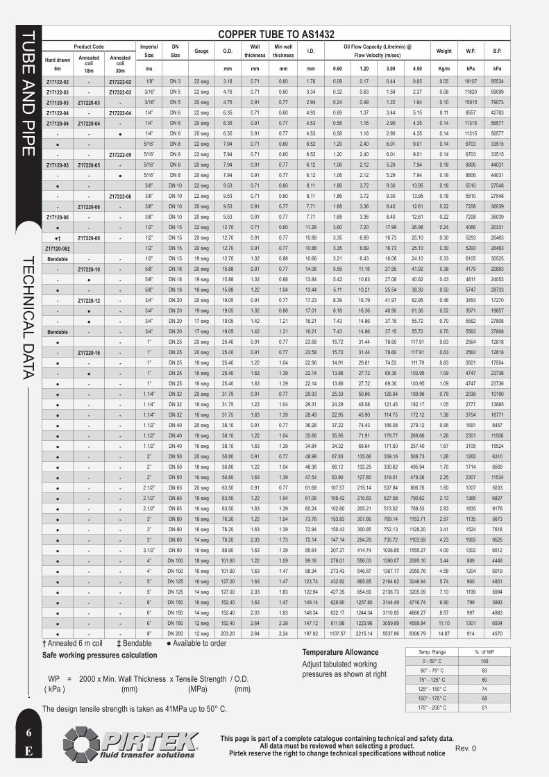
COPPER TUBE TO AS1432Product Code Imperial
SizeDN
SizeGauge O.D.
Wallthickness
Min wallthickness
I.D.Oil Flow Capacity (Litre/min) @
Flow Velocity (m/sec)Weight W.P. B.P.
Hard drawn6m
Annealed coil18m
Annealed coil30m ins mm mm mm mm 0.60 1.20 3.00 4.50 Kg/m kPa kPa
Z17122-02 - Z17222-02 1/8” DN 3 22 swg 3.18 0.71 0.60 1.76 0.09 0.17 0.44 0.65 0.05 19107 95534
Z17122-03 - Z17222-03 3/16” DN 5 22 swg 4.76 0.71 0.60 3.34 0.32 0.63 1.58 2.37 0.08 11820 59099
Z17120-03 Z17220-03 - 3/16” DN 5 20 swg 4.76 0.91 0.77 2.94 0.24 0.49 1.22 1.84 0.10 15815 79073
Z17122-04 - Z17222-04 1/4” DN 6 22 swg 6.35 0.71 0.60 4.93 0.69 1.37 3.44 5.15 0.11 8557 42783
Z17120-04 Z17220-04 - 1/4” DN 6 20 swg 6.35 0.91 0.77 4.53 0.58 1.16 2.90 4.35 0.14 11315 56577
- - ● 1/4” DN 6 20 swg 6.35 0.91 0.77 4.53 0.58 1.16 2.90 4.35 0.14 11315 56577
● - 5/16” DN 8 22 swg 7.94 0.71 0.60 6.52 1.20 2.40 6.01 9.01 0.14 6703 33515
- - Z17222-05 5/16” DN 8 22 swg 7.94 0.71 0.60 6.52 1.20 2.40 6.01 9.01 0.14 6703 33515
Z17120-05 Z17220-05 - 5/16” DN 8 20 swg 7.94 0.91 0.77 6.12 1.06 2.12 5.29 7.94 0.18 8806 44031
- - ● 5/16” DN 8 20 swg 7.94 0.91 0.77 6.12 1.06 2.12 5.29 7.94 0.18 8806 44031
● - 3/8” DN 10 22 swg 9.53 0.71 0.60 8.11 1.86 3.72 9.30 13.95 0.18 5510 27548
- - Z17222-06 3/8” DN 10 22 swg 9.53 0.71 0.60 8.11 1.86 3.72 9.30 13.95 0.18 5510 27548
- Z17220-06 - 3/8” DN 10 20 swg 9.53 0.91 0.77 7.71 1.68 3.36 8.40 12.61 0.22 7208 36039
Z17120-06 - - 3/8” DN 10 20 swg 9.53 0.91 0.77 7.71 1.68 3.36 8.40 12.61 0.22 7208 36039
● - - 1/2” DN 15 22 swg 12.70 0.71 0.60 11.28 3.60 7.20 17.99 26.98 0.24 4066 20331
●† Z17220-08 - 1/2” DN 15 20 swg 12.70 0.91 0.77 10.88 3.35 6.69 16.73 25.10 0.30 5293 26463
Z17120-08‡ 1/2” DN 15 20 swg 12.70 0.91 0.77 10.88 3.35 6.69 16.73 25.10 0.30 5293 26463
Bendable - - 1/2” DN 15 19 swg 12.70 1.02 0.88 10.66 3.21 6.43 16.06 24.10 0.33 6105 30525
- Z17220-10 - 5/8” DN 18 20 swg 15.88 0.91 0.77 14.06 5.59 11.18 27.95 41.92 0.38 4179 20893
- ● - 5/8” DN 18 19 swg 15.88 1.02 0.88 13.84 5.42 10.83 27.08 40.62 0.43 4811 24053
● - - 5/8” DN 18 18 swg 15.88 1.22 1.04 13.44 5.11 10.21 25.54 38.30 0.50 5747 28733
- Z17220-12 - 3/4” DN 20 20 swg 19.05 0.91 0.77 17.23 8.39 16.79 41.97 62.95 0.46 3454 17270
- ● - 3/4” DN 20 19 swg 19.05 1.02 0.88 17.01 8.18 16.36 40.90 61.36 0.52 3971 19857
- ● - 3/4” DN 20 17 swg 19.05 1.42 1.21 16.21 7.43 14.86 37.15 55.72 0.70 5562 27808
Bendable - - 3/4” DN 20 17 swg 19.05 1.42 1.21 16.21 7.43 14.86 37.15 55.72 0.70 5562 27808
● - 1” DN 25 20 swg 25.40 0.91 0.77 23.58 15.72 31.44 78.60 117.91 0.63 2564 12818
- Z17220-16 - 1” DN 25 20 swg 25.40 0.91 0.77 23.58 15.72 31.44 78.60 117.91 0.63 2564 12818
● - - 1” DN 25 18 swg 25.40 1.22 1.04 22.96 14.91 29.81 74.53 111.79 0.83 3501 17504
- ● - 1” DN 25 16 swg 25.40 1.63 1.39 22.14 13.86 27.72 69.30 103.95 1.09 4747 23736
● - - 1” DN 25 16 swg 25.40 1.63 1.39 22.14 13.86 27.72 69.30 103.95 1.09 4747 23736
● - - 1.1/4” DN 32 20 swg 31.75 0.91 0.77 29.93 25.33 50.66 126.64 189.96 0.79 2038 10190
● - - 1.1/4” DN 32 18 swg 31.75 1.22 1.04 29.31 24.29 48.58 121.45 182.17 1.05 2777 13885
● - - 1.1/4” DN 32 16 swg 31.75 1.63 1.39 28.49 22.95 45.90 114.75 172.12 1.38 3754 18771
● - - 1.1/2” DN 40 20 swg 38.10 0.91 0.77 36.28 37.22 74.43 186.08 279.12 0.95 1691 8457
● - - 1.1/2” DN 40 18 swg 38.10 1.22 1.04 35.66 35.95 71.91 179.77 269.66 1.26 2301 11506
● - - 1.1/2” DN 40 16 swg 38.10 1.63 1.39 34.84 34.32 68.64 171.60 257.40 1.67 3105 15524
● - - 2” DN 50 20 swg 50.80 0.91 0.77 48.98 67.83 135.66 339.16 508.73 1.28 1262 6310
● - - 2” DN 50 18 swg 50.80 1.22 1.04 48.36 66.12 132.25 330.62 495.94 1.70 1714 8569
● - - 2” DN 50 16 swg 50.80 1.63 1.39 47.54 63.90 127.80 319.51 479.26 2.25 2307 11534
● - - 2.1/2” DN 65 20 swg 63.50 0.91 0.77 61.68 107.57 215.14 537.84 806.76 1.60 1007 5033
● - - 2.1/2” DN 65 18 swg 63.50 1.22 1.04 61.06 105.42 210.83 527.08 790.62 2.13 1365 6827
● - - 2.1/2” DN 65 16 swg 63.50 1.63 1.39 60.24 102.60 205.21 513.02 769.53 2.83 1835 9176
● - - 3” DN 80 18 swg 76.20 1.22 1.04 73.76 153.83 307.66 769.14 1153.71 2.57 1135 5673
● - - 3” DN 80 16 swg 76.20 1.63 1.39 72.94 150.43 300.85 752.13 1128.20 3.41 1524 7618
● - - 3” DN 80 14 swg 76.20 2.03 1.73 72.14 147.14 294.29 735.72 1103.59 4.23 1905 9525
● - - 3.1/2” DN 90 16 swg 88.90 1.63 1.39 85.64 207.37 414.74 1036.85 1555.27 4.00 1302 6512
● - - 4” DN 100 18 swg 101.60 1.22 1.09 99.16 278.01 556.03 1390.07 2085.10 3.44 889 4446
● - - 4” DN 100 16 swg 101.60 1.63 1.47 98.34 273.43 546.87 1367.17 2050.76 4.58 1204 6019
● - - 5” DN 125 16 swg 127.00 1.63 1.47 123.74 432.92 865.85 2164.62 3246.94 5.74 960 4801
● - - 5” DN 125 14 swg 127.00 2.03 1.83 122.94 427.35 854.69 2136.73 3205.09 7.13 1199 5994
● - - 6” DN 150 16 swg 152.40 1.63 1.47 149.14 628.90 1257.80 3144.49 4716.74 6.90 799 3993
● - - 6” DN 150 14 swg 152.40 2.03 1.83 148.34 622.17 1244.34 3110.85 4666.27 8.57 997 4983
● - - 6” DN 150 12 swg 152.40 2.64 2.38 147.12 611.98 1223.96 3059.89 4589.84 11.10 1301 6504
● - - 8” DN 200 12 swg 203.20 2.64 2.24 197.92 1107.57 2215.14 5537.86 8306.79 14.87 914 4570
† Annealed 6 m coil ‡ Bendable ● Available to orderSafe working pressures calculation
WP = 2000 x Min. Wall Thickness x Tensile Strength / O.D. ( kPa ) (mm) (MPa) (mm)
The design tensile strength is taken as 41MPa up to 50° C.
Temperature AllowanceAdjust tabulated working pressures as shown at right
Temp. Range % of WP0 - 50° C 100
50° - 75° C 8375° - 125° C 80
125° - 150° C 74150° - 175° C 68175° - 200° C 51
This page is part of a complete catalogue containing technical and safety data.All data must be reviewed when selecting a product.
Pirtek reserve the right to change technical specifications without notice E
TUBE
AN
D PIPE
TUBE
CLA
MPS
7Rev. 0
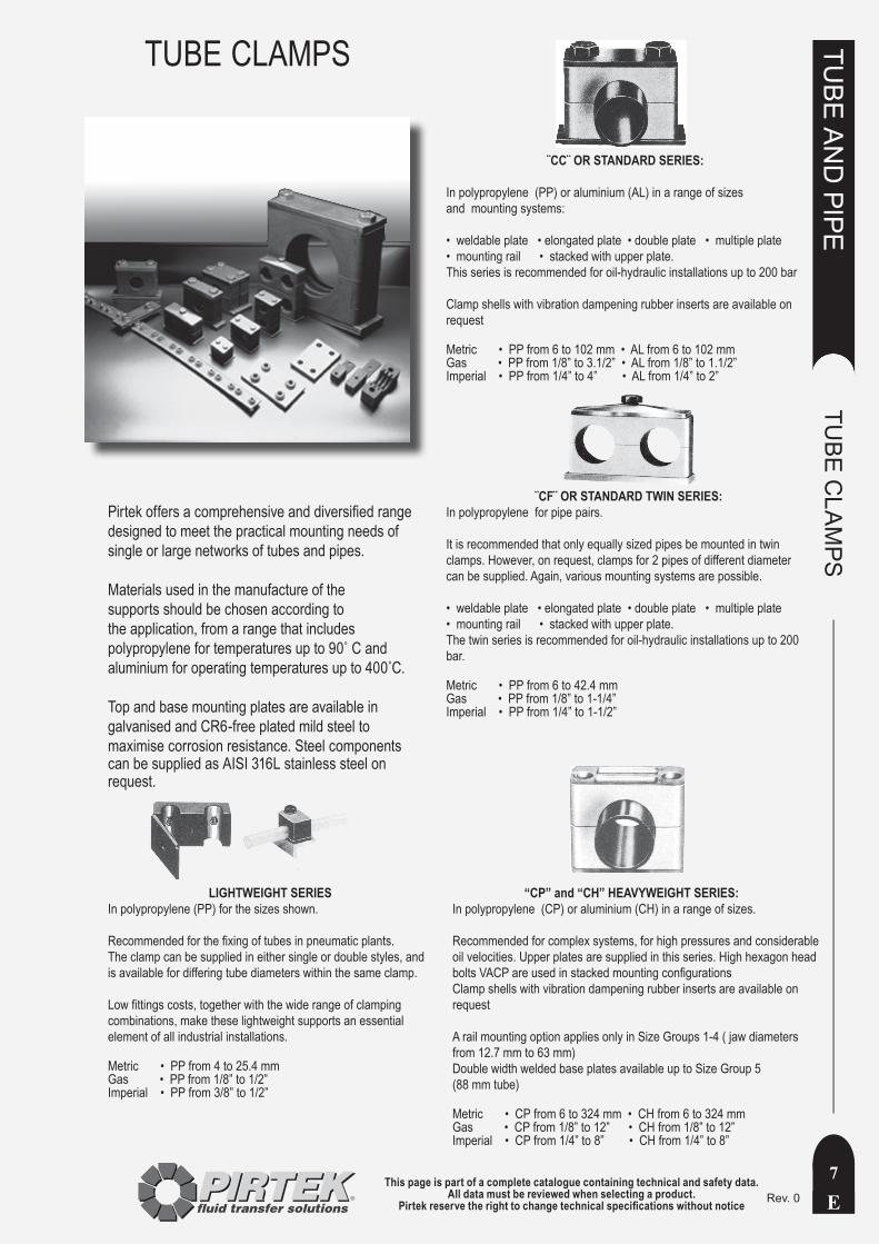
¨CC¨ OR STANDARD SERIES:
In polypropylene (PP) or aluminium (AL) in a range of sizesand mounting systems:
• weldable plate • elongated plate • double plate • multiple plate • mounting rail • stacked with upper plate. This series is recommended for oil-hydraulic installations up to 200 bar
Clamp shells with vibration dampening rubber inserts are available on request
Metric • PP from 6 to 102 mm • AL from 6 to 102 mmGas • PP from 1/8” to 3.1/2” • AL from 1/8” to 1.1/2”Imperial • PP from 1/4” to 4” • AL from 1/4” to 2”
LIGHTWEIGHT SERIESIn polypropylene (PP) for the sizes shown.
Recommended for the fixing of tubes in pneumatic plants. The clamp can be supplied in either single or double styles, and is available for differing tube diameters within the same clamp.
Low fittings costs, together with the wide range of clamping combinations, make these lightweight supports an essential element of all industrial installations.
Metric • PP from 4 to 25.4 mm Gas • PP from 1/8” to 1/2” Imperial • PP from 3/8” to 1/2”
¨CF¨ OR STANDARD TWIN SERIES: In polypropylene for pipe pairs.
It is recommended that only equally sized pipes be mounted in twin clamps. However, on request, clamps for 2 pipes of different diameter can be supplied. Again, various mounting systems are possible.
• weldable plate • elongated plate • double plate • multiple plate • mounting rail • stacked with upper plate. The twin series is recommended for oil-hydraulic installations up to 200 bar.
Metric • PP from 6 to 42.4 mm Gas • PP from 1/8” to 1-1/4” Imperial • PP from 1/4” to 1-1/2”
“CP” and “CH” HEAVYWEIGHT SERIES: In polypropylene (CP) or aluminium (CH) in a range of sizes.
Recommended for complex systems, for high pressures and considerable oil velocities. Upper plates are supplied in this series. High hexagon head bolts VACP are used in stacked mounting configurationsClamp shells with vibration dampening rubber inserts are available on request
A rail mounting option applies only in Size Groups 1-4 ( jaw diameters from 12.7 mm to 63 mm)Double width welded base plates available up to Size Group 5(88 mm tube)
Metric • CP from 6 to 324 mm • CH from 6 to 324 mmGas • CP from 1/8” to 12” • CH from 1/8” to 12”Imperial • CP from 1/4” to 8” • CH from 1/4” to 8”
Pirtek offers a comprehensive and diversified range designed to meet the practical mounting needs of single or large networks of tubes and pipes.
Materials used in the manufacture of the supports should be chosen according to the application, from a range that includes polypropylene for temperatures up to 90˚ C and aluminium for operating temperatures up to 400˚C.
Top and base mounting plates are available in galvanised and CR6-free plated mild steel to maximise corrosion resistance. Steel components can be supplied as AISI 316L stainless steel on request.
TUBE CLAMPS
This page is part of a complete catalogue containing technical and safety data.All data must be reviewed when selecting a product.
Pirtek reserve the right to change technical specifications without noticeE
TUBE
AN
D PIPE
TUBE
CLA
MPS
8Rev. 0
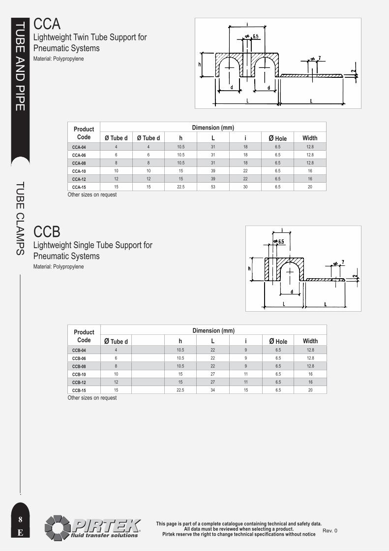
CCA Lightweight Twin Tube Support for Pneumatic SystemsMaterial: Polypropylene
Product Code
Dimension (mm) Ø Tube d Ø Tube d h L i Ø Hole Width
CCA-04 4 4 10.5 31 18 6.5 12.8
CCA-06 6 6 10.5 31 18 6.5 12.8
CCA-08 8 8 10.5 31 18 6.5 12.8
CCA-10 10 10 15 39 22 6.5 16
CCA-12 12 12 15 39 22 6.5 16
CCA-15 15 15 22.5 53 30 6.5 20
CCBLightweight Single Tube Support for Pneumatic SystemsMaterial: Polypropylene
Product Code
Dimension (mm) Ø Tube d h L i Ø Hole Width
CCB-04 4 10.5 22 9 6.5 12.8
CCB-06 6 10.5 22 9 6.5 12.8
CCB-08 8 10.5 22 9 6.5 12.8
CCB-10 10 15 27 11 6.5 16
CCB-12 12 15 27 11 6.5 16
CCB-15 15 22.5 34 15 6.5 20
Other sizes on request
Other sizes on request
This page is part of a complete catalogue containing technical and safety data.All data must be reviewed when selecting a product.
Pirtek reserve the right to change technical specifications without notice E
TUBE
AN
D PIPE
TUBE
CLA
MPS
9Rev.3.1
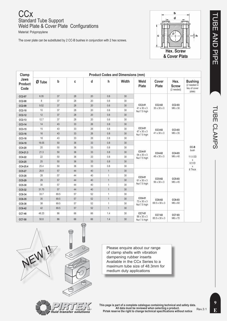
CCxStandard Tube Support Weld Plate & Cover Plate ConfigurationsMaterial: Polypropylene
The cover plate can be substituted by 2 CC-B bushes in conjunction with 2 hex screws.
Clamp Jaws
Product Code
Product Codes and Dimensions (mm)
Ø Tube b c d h Width Weld Plate
Cover Plate
Hex. Screw
(2 needed)
Bushing(2 needed in lieu of cover
plate)
CC2-07 6.35 37 28 20 0.6 30
CC2-0141 x 30 x 3Nut 7.5 high
CC2-0235 x 30 x 3
CC2-03M6 x 30
CC-Bbush
11.5 ODx
6.5 IDx
8 Thick
CC2-08 8 37 28 20 0.6 30
CC2-09 9.52 37 28 20 0.6 30
CC2-10 10 37 28 20 0.6 30
CC2-12 12 37 28 20 0.6 30
CC2-13 12.7 37 28 20 0.6 30
CC3-14 14 43 33 26 0.8 30CC3-01
47 x 30 x 3Nut 7.5 high
CC3-0241 x 30 x 3
CC3-03M6 x 35
CC3-15 15 43 33 26 0.8 30
CC3-16 16 43 33 26 0.8 30
CC3-18 18 43 33 26 0.8 30
CC4-19 19.05 50 36 33 0.8 30
CC4-0154 x 30 x 3Nut 7.5 high
CC4-0248 x 30 x 3
CC4-03M6 x 40
CC4-20 20 50 36 33 0.8 30
CC4-21.3 21.3 50 36 33 0.8 30
CC4-22 22 50 36 33 0.8 30
CC4-25 25 50 36 33 0.8 30
CC4-25.4 25.4 50 36 33 0.8 30
CC5-27 26.9 57 44 40 1 30
CC5-0161 x 30 x 3Nut 7.5 high
CC5-0256 x 30 x 3
CC5-03M6 x 45
CC5-28 28 57 44 40 1 30
CC5-29 29 57 44 40 1 30
CC5-30 30 57 44 40 1 30
CC5-32 31.75 57 44 40 1 30
CC6-34 33.7 69.5 57 52 1 30CC6-01
73 x 30 x 3Nut 7.5 high
CC6-0269.5 x 30 x 3
CC6-03M6 x 60
CC6-35 35 69.5 57 52 1 30
CC6-38 38 69.5 57 52 1 30
CC6-42 42 69.5 57 52 1 30
CC7-48 48.25 86 66 66 1.4 30 CC7-0188 x 30 x 3Nut 7.5 high
CC7-0285.5 x 30 x 3
CC7-03M6 x 70CC7-50 50.8 86 66 66 1.4 30
NEW !!Please enquire about our range of clamp shells with vibration dampening rubber inserts Available in the CCx Series to a maximum tube size of 48.3mm for medium duty applications

This page is part of a complete catalogue containing technical and safety data.All data must be reviewed when selecting a product.
Pirtek reserve the right to change technical specifications without noticeE
TUBE
AN
D PIPE
TUBE
CLA
MPS
10Rev. 0
CCxStandard Tube Support Stacked Configuration *Material: Polypropylene
* Please note that the arrangement of hex screws with cover plate CCx-02 as illustrated can be substituted with hex screws and bushes CC-B
Clamp JawsProduct Code
Product Codes and Dimensions mm
Ø Tube Weld Plate Cover Plate Hex. Screw Stacking Screw
Flat Washer(2 needed)
Lock Washer(2 needed)
CC2-07 6.35
CC2-0141 x 30 x 3Nut 7.5 high
CC2-0235 x 30 x 3
CC2-03M6 x 30
CC2-VAM6 x 21L = 35L2 = 21
CC-RP11.5 x 6.3
Round1.5 thick
CC-PB20 x 20
with 11 mm AF
Hex. Hole
CC2-08 8
CC2-09 9.52
CC2-10 10
CC2-12 12
CC2-13 12.7
CC3-14 14CC3-01
47 x 30 x 3Nut 7.5 high
CC3-0241 x 30 x 3
CC3-03M6 x 35
CC3-VAM6 x 27L = 41L2 = 27
CC3-15 15
CC3-16 16
CC3-18 18
CC4-19 19.05CC4-01
54 x 30 x 3Nut 7.5 high
CC4-0248 x 30 x 3
CC4-03M6 x 40
CC4-VAM6 x 29L = 43L2 = 29
CC4-20 20
CC4-22 22
CC4-25 25
CC5-27 26.9CC5-01
61 x 30 x 3Nut 7.5 high
CC5-0256 x 30 x 3
CC5-03M6 x 45
CC5-VAM6 x 39L = 53L2 = 39
CC5-28 28
CC5-30 30
CC5-32 31.75
CC6-34 33.7CC6-01
73 x 30 x 3Nut 7.5 high
CC6-0269.5 x 30 x 3
CC6-03M6 x 60
CC6-VAM6 x 49L = 63L2 = 49
CC6-35 35
CC6-38 38
CC6-42 42
CC7-48 48.25 CC7-0188 x 30 x 3Nut 7.5 high
CC7-0285.5 x 30 x 3
CC7-03M6 x 70
CC7-VAM6 x 59
L=73L2=59CC7-50 50.8
This page is part of a complete catalogue containing technical and safety data.All data must be reviewed when selecting a product.
Pirtek reserve the right to change technical specifications without notice E
TUBE
AN
D PIPE
TUBE
CLA
MPS
11Rev. 0
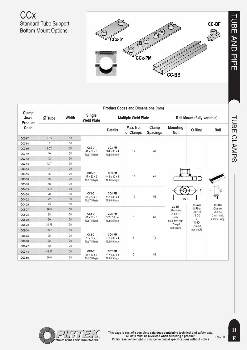
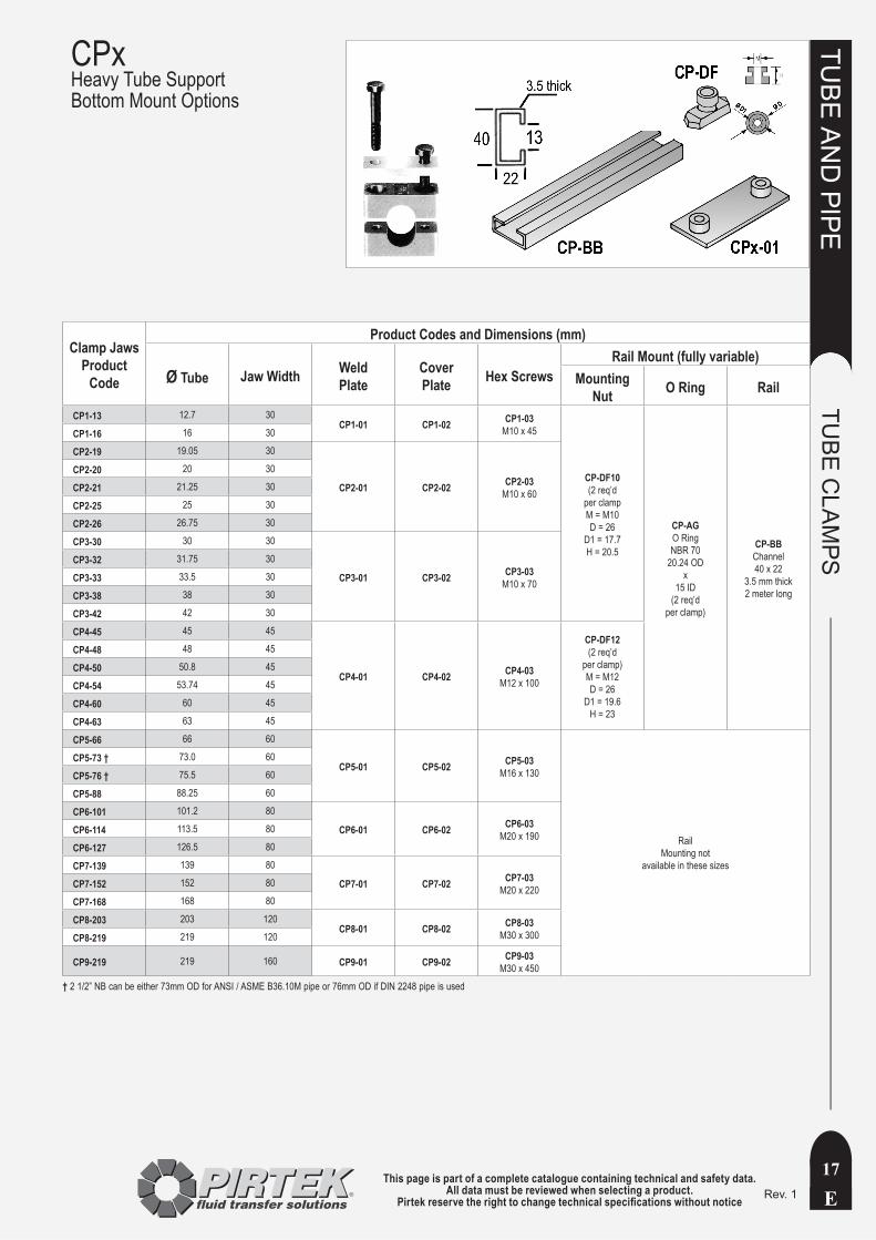
CCxStandard Tube Support Bottom Mount Options
Clamp Jaws
Product Code
Product Codes and Dimensions (mm)
Ø Tube Width Single Weld Plate Multiple Weld Plate Rail Mount (fully variable)
Details Max. No.of Clamps
Clamp Spacings
Mounting Nut O Ring Rail
CC2-07 6.35 30
CC2-0141 x 30 x 3Nut 7.5 high
CC2-PM384 x 30 x 4Nut 6.5 high
10 39
CC-DFRhombus24.5 x 11
withnut 8 mm high
(2 req’d per stack)
CC-AGO RingNBR 7015 OD
x10 ID
(2 req’d per stack)
CC-BBChannel28 x 14
2 mm thick2 meter long
CC2-08 8 30
CC2-09 9.52 30
CC2-10 10 30
CC2-12 12 30
CC2-13 12.7 30
CC3-14 14 30CC3-01
47 x 30 x 3Nut 7.5 high
CC3-PM443 x 30 x 4Nut 6.5 high
10 45CC3-15 15 30
CC3-16 16 30
CC3-18 18 30
CC4-19 19.05 30CC4-01
54 x 30 x 3Nut 7.5 high
CC4-PM513 x 30 x 4Nut 6.5 high
10 52CC4-20 20 30
CC4-22 22 30
CC4-25 25 30
CC5-27 26.9 30CC5-01
61 x 30 x 3Nut 7.5 high
CC5-PM301x 30 x 4Nut 6.5 high
5 59CC5-28 28 30
CC5-30 30 30
CC5-32 31.75 30
CC6-34 33.7 30CC6-01
73 x 30 x 3Nut 7.5 high
CC6-PM373 x 30 x 4Nut 6.5 high
5 72CC6-35 35 30
CC6-38 38 30
CC6-42 42 30
CC7-48 48.25 30 CC7-0188 x 30 x 3Nut 7.6 high
CC7-PM447 x 30 x 4Nut 6.5 high
5 86CC7-50 50.8 30

This page is part of a complete catalogue containing technical and safety data.All data must be reviewed when selecting a product.
Pirtek reserve the right to change technical specifications without noticeE
TUBE
AN
D PIPE
TUBE
CLA
MPS
12Rev. 0
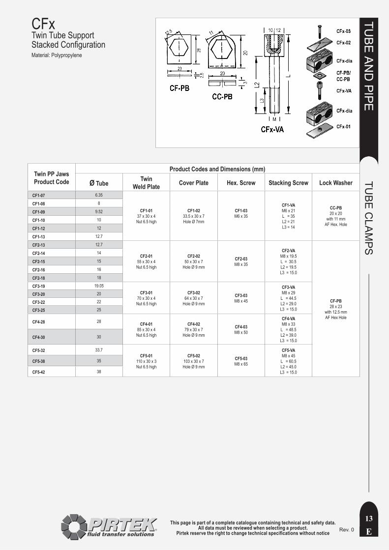
CFxTwin Tube Support Weld Plate & Top Plate ConfigurationMaterial: Polypropylene
Clamp Jaws
Product Code
Product Codes and Dimensions (mm)
Ø Tube b c d f Width Weld Plate Top Plate Hex. Screw
CF1-07 6.35 36 27 20 0.6 30
CF1-0137 x 30 x 4Nut 6.5 high
CF1-0233.5 x 30 x 7Hole Ø 7mm
CF1-03M6 x 35
CF1-08 8 36 27 20 0.6 30
CF1-09 9.52 36 27 20 0.6 30
CF1-10 10 36 27 20 0.6 30
CF1-12 12 36 27 20 0.6 30
CF1-13 12.7 36 27 20 0.6 30
CF2-13 12.7 54 27 29 0.8 30
CF2-0155 x 30 x 4Nut 6.5 high
CF2-0250 x 30 x 7
Hole Ø 9 mm
CF2-03M8 x 35
CF2-14 14 54 27 29 0.8 30
CF2-15 15 54 27 29 0.8 30
CF2-16 16 54 27 29 0.8 30
CF2-18 18 54 27 29 0.8 30
CF3-19 19.05 67 37 36 1 30
CF3-0170 x 30 x 4Nut 6.5 high
CF3-0264 x 30 x 7
Hole Ø 9 mm
CF3-03M8 x 45
CF3-20 20 67 37 36 1 30
CF3-21.3 21.3 67 37 36 1 30
CF3-22 22 67 37 36 1 30
CF3-25 25 67 37 36 1 30
CF4-26.9 26.9 81 42 45 1 30 CF4-0185 x 30 x 4Nut 6.5 high
CF4-0279 x 30 x 7
Hole Ø 9 mm
CF4-03M8 x 50CF4-28 28 81 42 45 1 30
CF4-30 30 81 42 45 1 30
CF5-32 31.75 106 53 56 1.2 30 CF5-01110 x 30 x 3Nut 6.5 high
CF5-02103 x 30 x 7
CF5-03M8 x 65CF5-38 38 106 53 56 1.2 30
CF5-42 42 106 53 56 1.2 30
This page is part of a complete catalogue containing technical and safety data.All data must be reviewed when selecting a product.
Pirtek reserve the right to change technical specifications without notice E
TUBE
AN
D PIPE
TUBE
CLA
MPS
13Rev. 0
CFxTwin Tube Support Stacked ConfigurationMaterial: Polypropylene
Twin PP JawsProduct Code
Product Codes and Dimensions (mm)
Ø Tube Twin Weld Plate Cover Plate Hex. Screw Stacking Screw Lock Washer
CF1-07 6.35
CF1-0137 x 30 x 4Nut 6.5 high
CF1-0233.5 x 30 x 7Hole Ø 7mm
CF1-03M6 x 35
CF1-VAM6 x 21L = 35L2 = 21L3 = 14
CC-PB20 x 20
with 11 mm AF Hex. Hole
CF1-08 8
CF1-09 9.52
CF1-10 10
CF1-12 12
CF1-13 12.7
CF2-13 12.7
CF2-0155 x 30 x 4Nut 6.5 high
CF2-0250 x 30 x 7
Hole Ø 9 mm
CF2-03M8 x 35
CF2-VAM8 x 19.5L = 30.5L2 = 19.5L3 = 15.0
CF-PB28 x 23
with 12.5 mm AF Hex Hole
CF2-14 14
CF2-15 15
CF2-16 16
CF2-18 18
CF3-19 19.05CF3-01
70 x 30 x 4Nut 6.5 high
CF3-0264 x 30 x 7
Hole Ø 9 mm
CF3-03M8 x 45
CF3-VAM8 x 29
L = 44.5L2 = 29.0L3 = 15.0
CF3-20 20
CF3-22 22
CF3-25 25
CF4-28 28 CF4-0185 x 30 x 4Nut 6.5 high
CF4-0279 x 30 x 7
Hole Ø 9 mm
CF4-03M8 x 50
CF4-VAM8 x 33
L = 48.5L2 = 39.0L3 = 15.0
CF4-30 30
CF5-32 33.7CF5-01
110 x 30 x 3Nut 6.5 high
CF5-02103 x 30 x 7Hole Ø 9 mm
CF5-03M8 x 65
CF5-VAM8 x 45
L = 60.5L2 = 45.0L3 = 15.0
CF5-38 35
CF5-42 38

This page is part of a complete catalogue containing technical and safety data.All data must be reviewed when selecting a product.
Pirtek reserve the right to change technical specifications without noticeE
TUBE
AN
D PIPE
TUBE
CLA
MPS
14Rev. 0
CFxTwin Tube Support Bottom Mount Options
Twin PP Jaws
Product Code
Product Codes and Dimensions (mm) Ø Tube Jaw Width Weld Plate Rail Mount (fully variable)
TwinWeld Plate Cover Plate Hex. Screw Mounting
Nut O Ring Rail
CF1-07 6.35 30
CF1-0137 x 30 x 4Nut 6.5 high
CF1-0233.5 x 30 x 7Hole Ø 7mm
CF1-03M6 x 35
CC-DFRhombus
with 6 mm Nut
CC-AGO RingNBR 7015 OD
x10 ID
CC-BBChannel28 x 14
2 mm thick2 meter long
CF1-08 8 30
CF1-09 9.52 30
CF1-10 10 30
CF1-12 12 30
CF1-13 12.7 30
CF2-13 12.7 30
CF2-0155 x 30 x 4Nut 6.5 high
CF2-0250 x 30 x 7
Hole Ø 9 mm
CF2-03M8 x 35
CF-DFRhombus
with 8 mm Nut
CC-AGO RingNBR 7015 OD
x10 ID
CF2-14 14 30
CF2-15 15 30
CF2-16 16 30
CF2-18 18 30
CF3-19 19.05 30CF3-01
70 x 30 x 4Nut 6.5 high
CF3-0264 x 30 x 7
Hole Ø 9 mm
CF3-03M8 x 45
CF3-20 20 30
CF3-22 22 30
CF3-25 25 30
CF4-28 28 30 CF4-0185 x 30 x 4Nut 6.5 high
CF4-0279 x 30 x 7
Hole Ø 9 mm
CF4-03M8 x 50CF4-30 30 30
CF5-32 31.75 30 CF5-01110 x 30 x 3Nut 6.5 high
CF5-02103 x 30 x 7Hole Ø 9 mm
CF5-03M8 x 65CF5-38 38 30
CF5-42 42 30
This page is part of a complete catalogue containing technical and safety data.All data must be reviewed when selecting a product.
Pirtek reserve the right to change technical specifications without notice E
TUBE
AN
D PIPE
TUBE
CLA
MPS
15Rev. 3.1
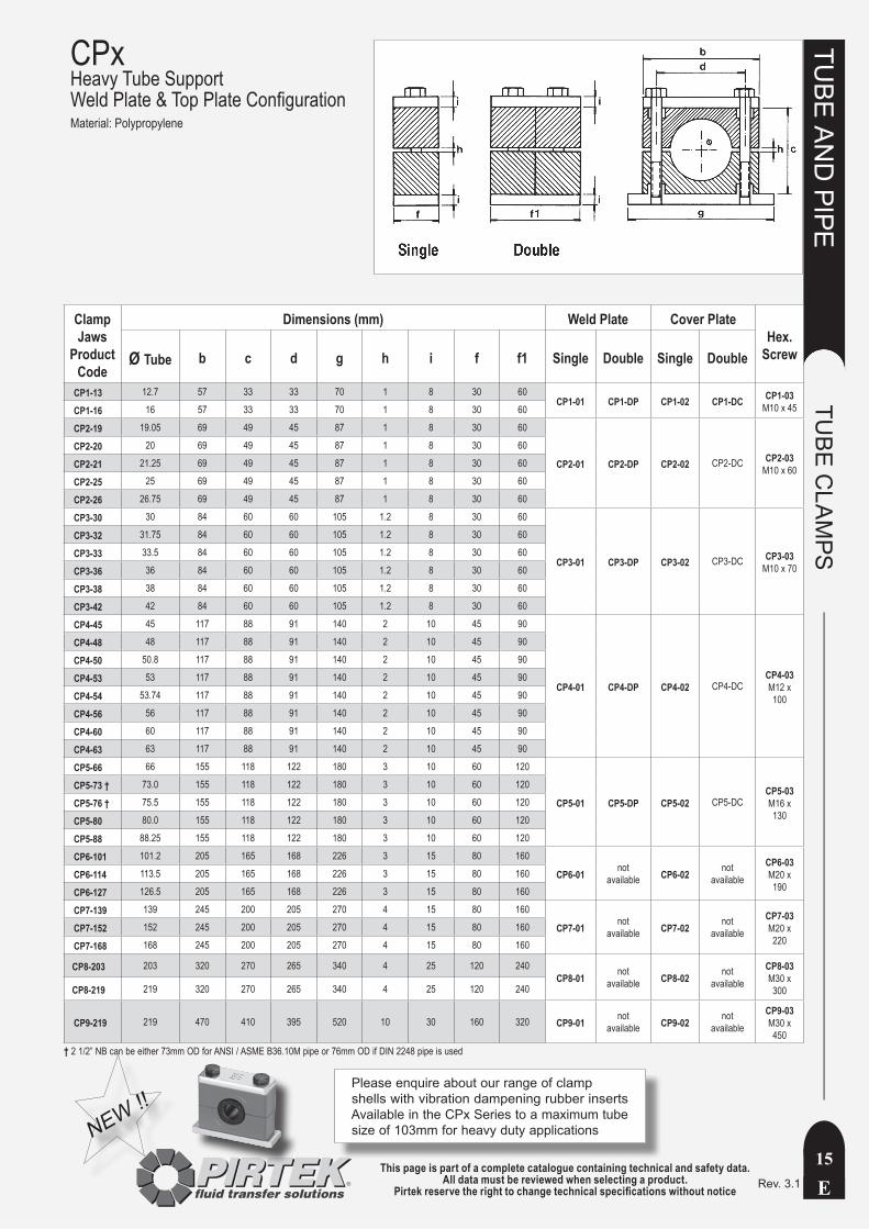
Clamp Jaws
Product Code
Dimensions (mm) Weld Plate Cover Plate Hex.
Screw Ø Tube b c d g h i f f1 Single Double Single Double
CP1-13 12.7 57 33 33 70 1 8 30 60CP1-01 CP1-DP CP1-02 CP1-DC CP1-03
M10 x 45CP1-16 16 57 33 33 70 1 8 30 60
CP2-19 19.05 69 49 45 87 1 8 30 60
CP2-01 CP2-DP CP2-02 CP2-DC CP2-03M10 x 60
CP2-20 20 69 49 45 87 1 8 30 60
CP2-21 21.25 69 49 45 87 1 8 30 60
CP2-25 25 69 49 45 87 1 8 30 60
CP2-26 26.75 69 49 45 87 1 8 30 60
CP3-30 30 84 60 60 105 1.2 8 30 60
CP3-01 CP3-DP CP3-02 CP3-DC CP3-03M10 x 70
CP3-32 31.75 84 60 60 105 1.2 8 30 60
CP3-33 33.5 84 60 60 105 1.2 8 30 60
CP3-36 36 84 60 60 105 1.2 8 30 60
CP3-38 38 84 60 60 105 1.2 8 30 60
CP3-42 42 84 60 60 105 1.2 8 30 60
CP4-45 45 117 88 91 140 2 10 45 90
CP4-01 CP4-DP CP4-02 CP4-DCCP4-03M12 x 100
CP4-48 48 117 88 91 140 2 10 45 90
CP4-50 50.8 117 88 91 140 2 10 45 90
CP4-53 53 117 88 91 140 2 10 45 90
CP4-54 53.74 117 88 91 140 2 10 45 90
CP4-56 56 117 88 91 140 2 10 45 90
CP4-60 60 117 88 91 140 2 10 45 90
CP4-63 63 117 88 91 140 2 10 45 90
CP5-66 66 155 118 122 180 3 10 60 120
CP5-01 CP5-DP CP5-02 CP5-DCCP5-03M16 x 130
CP5-73 † 73.0 155 118 122 180 3 10 60 120
CP5-76 † 75.5 155 118 122 180 3 10 60 120
CP5-80 80.0 155 118 122 180 3 10 60 120
CP5-88 88.25 155 118 122 180 3 10 60 120
CP6-101 101.2 205 165 168 226 3 15 80 160
CP6-01 notavailable CP6-02 not
available CP6-03M20 x 190
CP6-114 113.5 205 165 168 226 3 15 80 160
CP6-127 126.5 205 165 168 226 3 15 80 160
CP7-139 139 245 200 205 270 4 15 80 160
CP7-01 notavailable CP7-02 not
available CP7-03M20 x 220
CP7-152 152 245 200 205 270 4 15 80 160
CP7-168 168 245 200 205 270 4 15 80 160
CP8-203 203 320 270 265 340 4 25 120 240CP8-01 not
available CP8-02 notavailable
CP8-03M30 x 300CP8-219 219 320 270 265 340 4 25 120 240
CP9-219 219 470 410 395 520 10 30 160 320 CP9-01 notavailable CP9-02 not
available CP9-03M30 x 450
CPxHeavy Tube Support Weld Plate & Top Plate ConfigurationMaterial: Polypropylene
Please enquire about our range of clamp shells with vibration dampening rubber inserts Available in the CPx Series to a maximum tube size of 103mm for heavy duty applicationsNEW !!
† 2 1/2” NB can be either 73mm OD for ANSI / ASME B36.10M pipe or 76mm OD if DIN 2248 pipe is used
This page is part of a complete catalogue containing technical and safety data.All data must be reviewed when selecting a product.
Pirtek reserve the right to change technical specifications without noticeE
TUBE
AN
D PIPE
TUBE
CLA
MPS
16Rev. 1
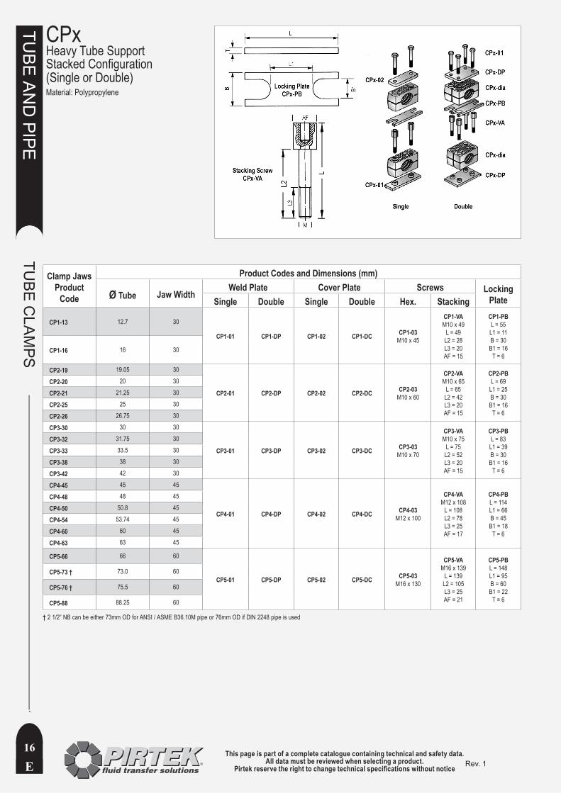
CPxHeavy Tube SupportStacked Configuration(Single or Double)Material: Polypropylene
Clamp JawsProduct
Code
Product Codes and Dimensions (mm)
Ø Tube Jaw WidthWeld Plate Cover Plate Screws Locking
Plate Single Double Single Double Hex. Stacking
CP1-13 12.7 30
CP1-01 CP1-DP CP1-02 CP1-DC CP1-03M10 x 45
CP1-VAM10 x 49
L = 49L2 = 28L3 = 20AF = 15
CP1-PBL = 55L1 = 11B = 30
B1 = 16T = 6
CP1-16 16 30
CP2-19 19.05 30
CP2-01 CP2-DP CP2-02 CP2-DC CP2-03M10 x 60
CP2-VAM10 x 65
L = 65L2 = 42L3 = 20AF = 15
CP2-PBL = 69
L1 = 25B = 30
B1 = 16T = 6
CP2-20 20 30
CP2-21 21.25 30
CP2-25 25 30
CP2-26 26.75 30
CP3-30 30 30
CP3-01 CP3-DP CP3-02 CP3-DC CP3-03M10 x 70
CP3-VAM10 x 75
L = 75L2 = 52L3 = 20AF = 15
CP3-PBL = 83
L1 = 39B = 30
B1 = 16T = 6
CP3-32 31.75 30
CP3-33 33.5 30
CP3-38 38 30
CP3-42 42 30
CP4-45 45 45
CP4-01 CP4-DP CP4-02 CP4-DC CP4-03M12 x 100
CP4-VAM12 x 108
L = 108L2 = 78L3 = 25AF = 17
CP4-PBL = 114L1 = 66B = 45
B1 = 18T = 6
CP4-48 48 45
CP4-50 50.8 45
CP4-54 53.74 45
CP4-60 60 45
CP4-63 63 45
CP5-66 66 60
CP5-01 CP5-DP CP5-02 CP5-DC CP5-03M16 x 130
CP5-VAM16 x 139
L = 139L2 = 105L3 = 25AF = 21
CP5-PBL = 148L1 = 95B = 60
B1 = 22T = 6
CP5-73 † 73.0 60
CP5-76 † 75.5 60
CP5-88 88.25 60
† 2 1/2” NB can be either 73mm OD for ANSI / ASME B36.10M pipe or 76mm OD if DIN 2248 pipe is used
This page is part of a complete catalogue containing technical and safety data.All data must be reviewed when selecting a product.
Pirtek reserve the right to change technical specifications without notice E
TUBE
AN
D PIPE
TUBE
CLA
MPS
17Rev. 1
CPxHeavy Tube Support Bottom Mount Options
Clamp JawsProduct
Code
Product Codes and Dimensions (mm)
Ø Tube Jaw Width Weld Plate
Cover Plate Hex Screws
Rail Mount (fully variable)Mounting
Nut O Ring Rail
CP1-13 12.7 30CP1-01 CP1-02 CP1-03
M10 x 45
CP-DF10(2 req’d
per clampM = M10D = 26
D1 = 17.7H = 20.5
CP-AGO RingNBR 70
20.24 ODx
15 ID(2 req’d
per clamp)
CP-BBChannel40 x 22
3.5 mm thick2 meter long
CP1-16 16 30
CP2-19 19.05 30
CP2-01 CP2-02 CP2-03M10 x 60
CP2-20 20 30
CP2-21 21.25 30
CP2-25 25 30
CP2-26 26.75 30
CP3-30 30 30
CP3-01 CP3-02 CP3-03M10 x 70
CP3-32 31.75 30
CP3-33 33.5 30
CP3-38 38 30
CP3-42 42 30
CP4-45 45 45
CP4-01 CP4-02 CP4-03M12 x 100
CP-DF12(2 req’d
per clamp)M = M12D = 26
D1 = 19.6H = 23
CP4-48 48 45
CP4-50 50.8 45
CP4-54 53.74 45
CP4-60 60 45
CP4-63 63 45
CP5-66 66 60
CP5-01 CP5-02 CP5-03M16 x 130
Rail Mounting not
available in these sizes
CP5-73 † 73.0 60
CP5-76 † 75.5 60
CP5-88 88.25 60
CP6-101 101.2 80
CP6-01 CP6-02 CP6-03M20 x 190CP6-114 113.5 80
CP6-127 126.5 80
CP7-139 139 80
CP7-01 CP7-02 CP7-03M20 x 220CP7-152 152 80
CP7-168 168 80
CP8-203 203 120CP8-01 CP8-02 CP8-03
M30 x 300CP8-219 219 120
CP9-219 219 160 CP9-01 CP9-02 CP9-03M30 x 450
† 2 1/2” NB can be either 73mm OD for ANSI / ASME B36.10M pipe or 76mm OD if DIN 2248 pipe is used
This page is part of a complete catalogue containing technical and safety data.All data must be reviewed when selecting a product.
Pirtek reserve the right to change technical specifications without noticeE
TUBE
AN
D PIPE
TUBE
CLA
MPS
18Rev. 0
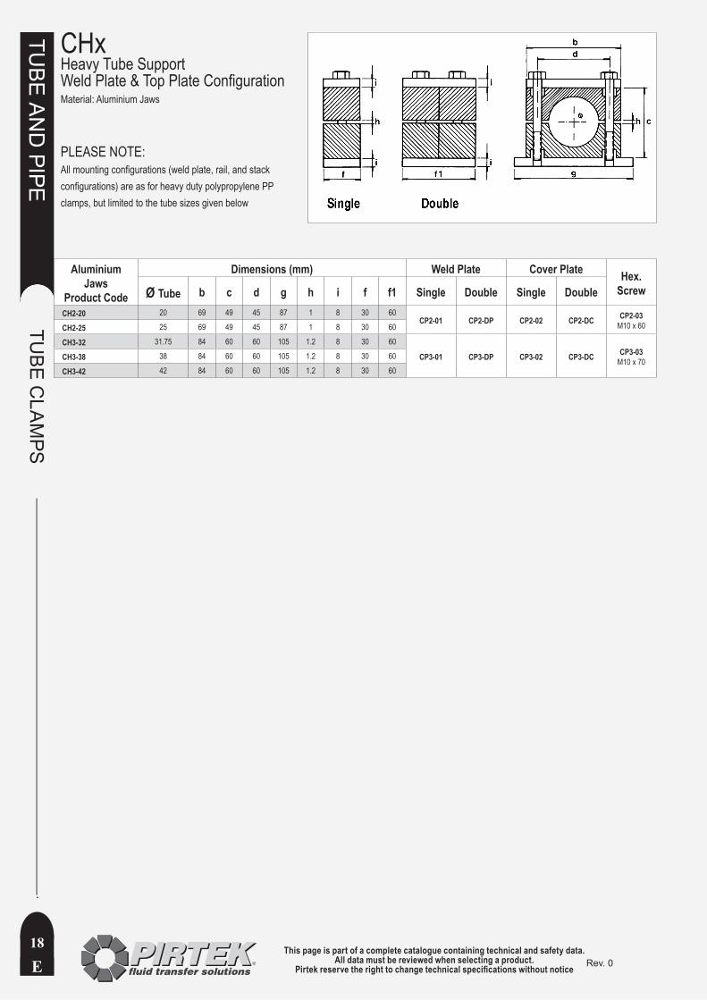
CHxHeavy Tube SupportWeld Plate & Top Plate ConfigurationMaterial: Aluminium Jaws
Aluminium Jaws
Product Code
Dimensions (mm) Weld Plate Cover Plate Hex. Screw Ø Tube b c d g h i f f1 Single Double Single Double
CH2-20 20 69 49 45 87 1 8 30 60CP2-01 CP2-DP CP2-02 CP2-DC CP2-03
M10 x 60CH2-25 25 69 49 45 87 1 8 30 60
CH3-32 31.75 84 60 60 105 1.2 8 30 60
CP3-01 CP3-DP CP3-02 CP3-DC CP3-03M10 x 70CH3-38 38 84 60 60 105 1.2 8 30 60
CH3-42 42 84 60 60 105 1.2 8 30 60
PLEASE NOTE:All mounting configurations (weld plate, rail, and stack configurations) are as for heavy duty polypropylene PP clamps, but limited to the tube sizes given below
This page is part of a complete catalogue containing technical and safety data.All data must be reviewed when selecting a product.
Pirtek reserve the right to change technical specifications without notice E
TUBE
AN
D PIPE
TUBE
CLA
MPS
19Rev. 0
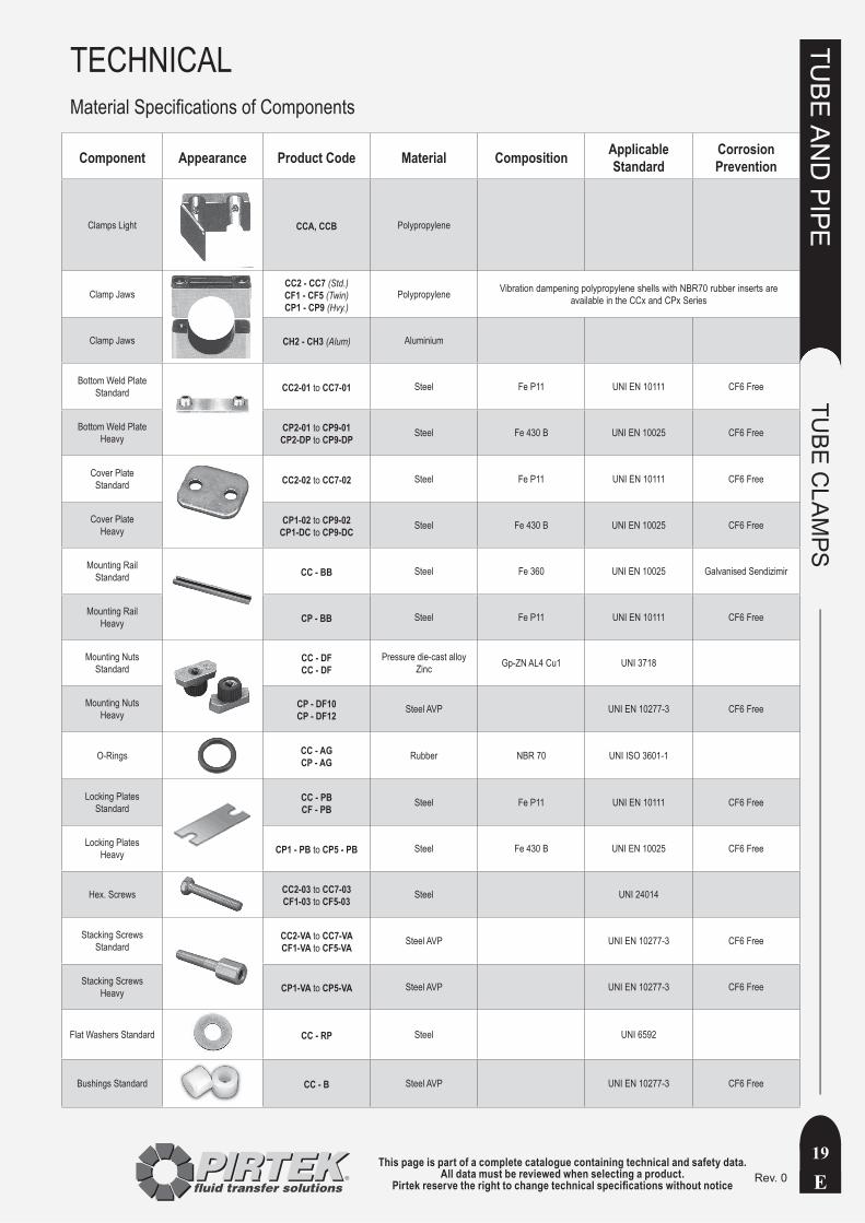
TECHNICALMaterial Specifications of Components
Component Appearance Product Code Material Composition Applicable Standard
Corrosion Prevention
Clamps Light CCA, CCB Polypropylene
Clamp JawsCC2 - CC7 (Std.)CF1 - CF5 (Twin)CP1 - CP9 (Hvy.)
Polypropylene Vibration dampening polypropylene shells with NBR70 rubber inserts are available in the CCx and CPx Series
Clamp Jaws CH2 - CH3 (Alum) Aluminium
Bottom Weld Plate Standard CC2-01 to CC7-01 Steel Fe P11 UNI EN 10111 CF6 Free
Bottom Weld Plate Heavy
CP2-01 to CP9-01CP2-DP to CP9-DP Steel Fe 430 B UNI EN 10025 CF6 Free
Cover Plate Standard CC2-02 to CC7-02 Steel Fe P11 UNI EN 10111 CF6 Free
Cover Plate Heavy
CP1-02 to CP9-02CP1-DC to CP9-DC Steel Fe 430 B UNI EN 10025 CF6 Free
Mounting Rail Standard CC - BB Steel Fe 360 UNI EN 10025 Galvanised Sendizimir
Mounting Rail Heavy CP - BB Steel Fe P11 UNI EN 10111 CF6 Free
Mounting Nuts Standard
CC - DFCC - DF
Pressure die-cast alloy Zinc Gp-ZN AL4 Cu1 UNI 3718
Mounting Nuts Heavy
CP - DF10CP - DF12 Steel AVP UNI EN 10277-3 CF6 Free
O-Rings CC - AGCP - AG Rubber NBR 70 UNI ISO 3601-1
Locking Plates Standard
CC - PBCF - PB Steel Fe P11 UNI EN 10111 CF6 Free
Locking Plates Heavy CP1 - PB to CP5 - PB Steel Fe 430 B UNI EN 10025 CF6 Free
Hex. Screws CC2-03 to CC7-03CF1-03 to CF5-03 Steel UNI 24014
Stacking Screws Standard
CC2-VA to CC7-VACF1-VA to CF5-VA Steel AVP UNI EN 10277-3 CF6 Free
Stacking Screws Heavy CP1-VA to CP5-VA Steel AVP UNI EN 10277-3 CF6 Free
Flat Washers Standard CC - RP Steel UNI 6592
Bushings Standard CC - B Steel AVP UNI EN 10277-3 CF6 Free
This page is part of a complete catalogue containing technical and safety data.All data must be reviewed when selecting a product.
Pirtek reserve the right to change technical specifications without noticeE
TUBE
AN
D PIPE
TUBE
CLA
MPS
20Rev. 0
TECHNICALClamp Shear Force Capability
The tabulated data applies for steel pipe St. 35.4. In each case, hex screws and cover plates have been used to maximise the load capability.
Sliding starts when the shear force ‘P’ is reached.
Clamp Series Type JawMaterial Bolt
Tightening Torque
(Nm)
Max. Shear Force P in the direction of
the pipe
(kN)CC2 Standard Single
Polypropylene
M6 8 1.2
CC3 Standard Single M6 8 1.5
CC4 Standard Single M6 8 1.7
CC5 Standard Single M6 8 1.8
CC6 Standard Single M6 8 2
CC7 Standard Single M6 8 2.2
CF1 Standard Twin
Polypropylene
M6 6 1.1
CF2 Standard Twin M8 13 2.5
CF3 Standard Twin M8 13 2.1
CF4 Standard Twin M8 13 2.9
CF5 Standard Twin M8 9 2.2
CP1 Heavy Single
Polypropylene
M10 13 1.8
CP2 Heavy Single M10 13 3
CP3 Heavy Single M10 15 3.5
CP4 Heavy Single M12 30 8.5
CP5 Heavy Single M16 46 11.5
CP6 Heavy Single M20 80 15
CP7 Heavy Single M20 100 30
CP8 Heavy Single M30 190 41
CP9 Heavy Single M30 210 125
CH2 Heavy SingleAluminium
M10 32 16
CH3 Heavy Single M10 37 16.5
Recommended Clamp Spacings
Tabulated data represents standard values for static loads. Clamps should always be applied at each side of a bend.
Clamp Series / Pipe OD (mm)
Clamp pitch A (m)
Clamp Series / Pipe OD (mm)
Clamp pitch A (m)
CC2 6 – 13.25 1 CP1 6 - 20 1.0
CC3 14 – 18 1.2 CP2 20 - 30 1.5
CC4 20 – 25.4 1.5 CP3 / CP4 30 - 50 2.2
CC5 28 – 32 1.5 CP4 / CP5 53 - 73 3
CC6 32 – 45 2.2 CP5 80 - 90 3.5
CC7 45 – 54 2.7 CP6 100 - 121 4.5
CP7 133 - 168 5
CP8 / CP9 168 - 219 6

This page is part of a complete catalogue containing technical and safety data.All data must be reviewed when selecting a product.
Pirtek reserve the right to change technical specifications without notice E
TUBE
AN
D PIPE
21Rev. 0
This page is intentionally blank

This page is part of a complete catalogue containing technical and safety data.All data must be reviewed when selecting a product.
Pirtek reserve the right to change technical specifications without noticeE
TUBE
AN
D PIPE
METR
IC C
OM
PRESSIO
N FITTIN
GS
22Rev. 0
This page is intentionally blank
This page is part of a complete catalogue containing technical and safety data.All data must be reviewed when selecting a product.
Pirtek reserve the right to change technical specifications without notice E
TUBE
AN
D PIPE
METR
IC C
OM
PRESSIO
N FITTIN
GS
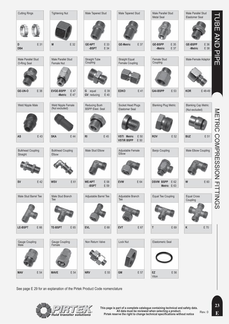
23Rev. 0
Cutting Rings Tightening Nut Male Tapered Stud Male Tapered Stud Male Parallel StudMetal Seal
Male Parallel StudElastomer Seal
D E 31DB4
M E 32 GE-NPT E 33 -BSPT E 34
GE-Metric E 37 GE-BSPP E 35 -Metric E 37
GE-BSPP E 36 -Metric E 38
Male Parallel StudO-Ring Seal
Male Parallel StudFemale Nut
Straight Tube Coupling
Straight Equal Female Coupling
Female Stud Coupling
Male-Female Adaptor
GE-UN-O E 38 EVGE-BSPP E 47 -Metric E 47
G equal E 39GV reducing E 40
EDKO E 41 GAI-BSPP E 53 KOR E 48-49
Weld Nipple Male Weld Nipple Female (Nut excluded)
Reducing Bush BSPP Elast. Seal
Socket Head PlugsElastomer Seal
Blanking Plug Metric Blanking Cap Metric(Nut excluded)
AS E 43
SKA E 44 RI E 45 VSTI Metric E 50VSTIR BSPP E 50
ROV E 52 BUZ E 51
Bulkhead CouplingStraight
Bulkhead CouplingElbow
Male Stud Elbow Adjustable Female Elbow
Banjo Coupling Male Elbow Coupling
SV E 42 WSV E 61 WE-NPT E 58 -BSPT E 59
EVW E 64 DSVW BSPP E 62 Metric E 63
W E 60
Male Stud Barrel Tee Male Stud Branch Tee
Adjustable Barrel Tee Adjustable Branch Tee
Equal Tee Coupling Equal Cross Coupling
LE-BSPT E 66 TE-BSPT E 65 EVL E 68
EVT E 67 T E 69
K E 70
Gauge Coupling Male
Gauge Coupling Female
Non Return Valve Lock Nut Elastomeric Seal
MAV E 54 MAVE E 54 NRV E 55
GM E 57 EZ E 56Viton
See page E 29 for an explanation of the Pirtek Product Code nomenclature
This page is part of a complete catalogue containing technical and safety data.All data must be reviewed when selecting a product.
Pirtek reserve the right to change technical specifications without noticeE
TUBE
AN
D PIPE
METR
IC C
OM
PRESSIO
N FITTIN
GS
24Rev. 0
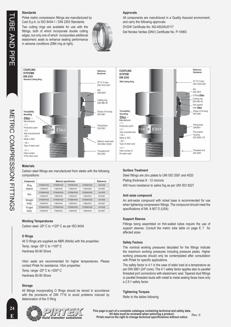
StandardsPirtek metric compression fittings are manufactured by Cast S.p.A. to ISO 8434-1 / DIN 2353 Standards. Two cutting rings are available for use with the fittings, both of which incorporate double cutting edges, but only one of which incorporates additional elastomeric seals to enhance sealing performance in adverse conditions (DB4 ring at right).
ApprovalsAll components are manufctured in a Quality Assured environment, and carry the following approvals:DVGW Certificate No. NG-4502AU0117Det Norske Veritas (DNV) Certificate No. P-10963
• T = Production plant• O = Year manufactured• CE = Made in EEC• 38 = Type of steel used
• 01 =Heat numberof the steel used
=Manufacturer
Threaded endDIN 3852
Metal to metal sealDIN 3852-1B/2B
Fitting BodyDIN 3901
ReferenceStandards:
Standard Cutting Ring
Traceabilitydecoding
ST 37.4 tubeDIN 1630-2391
Shape of housingDIN 3861
NutDIN 3870
Cutting ringDIN 3861-B
COUPLINGSYSTEMSDIN 2353
Traceabilitydecoding
COUPLINGSYSTEMDIN 2353
• T =Production plant• 0 =Year manufactured• CE =Made in EEC• 38 =Type of steel used
• 01 =Heat number ofthe steel used
Threaded endDIN 3852
Flat washer housingDIN 3852-11E
Fitting bodyDIN3901
Flat washersealShape of housingDIN 3861
O-RingCutting ringDIN 3861-B
NutDIN 3870
ST 37.4 tubeDIN 1630-2391
ReferenceStandards:
=Manufacturer
DB4 Cutting Ring
MaterialsCarbon steel fittings are manufactured from steels with the following compositions:
Component Material specification Reference
Ring /sleeve
CF9SMnPb36 CF9SMnPb28 CF9SMnPb36 CF9SMnPb28 UNI 4838
11SMnPb37 11SMnPb30 11SMnPb37 11SMnPb30 EN10087
NutCF9SMnPb36 CF9SMnPb28 CF9SMnPb36 CF9SMnPb28 UNI 4838
11SMnPb37 11SMnPb30 11SMnPb37 11SMnPb30 EN10087
Straight body
CF9SMnPb36 CF9SMnPb28 CF9SMnPb36 CF9SMnPb28 UNI 4838
11SMnPb37 11SMnPb30 11SMnPb37 11SMnPb30 EN10087
Forged body
CF9SMnPb36 CF9SMnPb28 CF9SMnPb36 CF9SMnPb28 UNI 4838
11SMnPb37 11SMnPb30 11SMnPb37 11SMnPb30 EN10087
Working TemperaturesCarbon steel -20º C to +120º C as per ISO 8434
O RingsAll O Rings are supplied as NBR (Nitrile) with the properties:Temp. range -35º C to +100º CHardness 80-90 Shore
Viton seals are recommended for higher temperatures. Please contact Pirtek for assistance. Viton properties:Temp. range -25º C to +200º CHardness 80-90 Shore
StorageAll fittings incorporating O Rings should be stored in accordance with the provisions of DIN 7716 to avoid problems induced by deterioration of the O Ring
Surface TreatmentSteel fittings are zinc plated to UNI ISO 2081 and 4520Plating thickness 8 - 12 microns400 hours resistance to saline fog as per UNI ISO 9227
Anti seize compoundAn anti-seize compound with nickel base is recommended for use when tightening compression fittings. The compound should meet the specifications of Mil. A 907 D (USA)
Support SleevesFittings being assembled on thin-walled tubes require the use of support sleeves. Consult the metric tube table on page E 7 for affected sizes
Safety FactorsThe nominal working pressures tabulated for the fittings indicate the maximum working pressures including pressure peaks. Higher working pressures should only be contemplated after consultation with Pirtek for specific applications.The safety factor is 4:1 in the case of static load at a temperature as per DIN 3861 (24º cone). The 4:1 safety factor applies also to parallel threaded port connections with elastomeric seal. Tapered stud fittings or parallel threaded studs with metal to metal sealing faces have only a 2.5:1 safety factor
Tightening TorquesRefer to the tables following
This page is part of a complete catalogue containing technical and safety data.All data must be reviewed when selecting a product.
Pirtek reserve the right to change technical specifications without notice E
TUBE
AN
D PIPE
METR
IC C
OM
PRESSIO
N FITTIN
GS
25Rev. 0
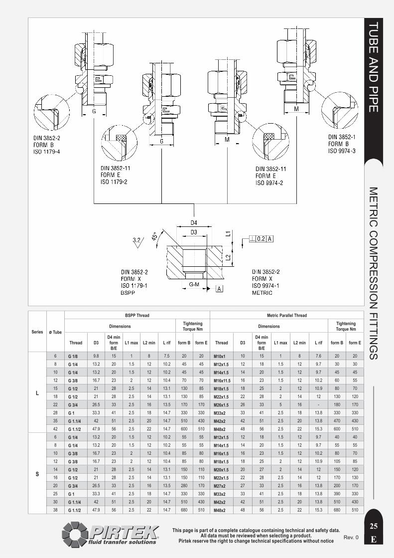
Series ø Tube
BSPP Thread Metric Parallel Thread
Dimensions Tightening Torque Nm Dimensions Tightening
Torque Nm
Thread D3D4 min
form B/E
L1 max L2 min L rif form B form E Thread D3D4 min
form B/E
L1 max L2 min L rif form B form E
L
6 G 1/8 9.8 15 1 8 7.5 20 20 M10x1 10 15 1 8 7.6 20 20
8 G 1/4 13.2 20 1.5 12 10.2 45 45 M12x1.5 12 18 1.5 12 9.7 30 30
10 G 1/4 13.2 20 1.5 12 10.2 45 45 M14x1.5 14 20 1.5 12 9.7 45 45
12 G 3/8 16.7 23 2 12 10.4 70 70 M16x11.5 16 23 1.5 12 10.2 60 55
15 G 1/2 21 28 2.5 14 13.1 130 85 M18x1.5 18 25 2 12 10.9 80 70
18 G 1/2 21 28 2.5 14 13.1 130 85 M22x1.5 22 28 2 14 12 130 120
22 G 3/4 26.5 33 2.5 16 13.5 170 170 M26x1.5 26 33 5 16 - 180 170
28 G 1 33.3 41 2.5 18 14.7 330 330 M33x2 33 41 2.5 18 13.8 330 330
35 G 1.1/4 42 51 2.5 20 14.7 510 430 M42x2 42 51 2.5 20 13.8 470 430
42 G 1.1/2 47.9 56 2.5 22 14.7 600 510 M48x2 48 56 2.5 22 15.3 600 510
S
6 G 1/4 13.2 20 1.5 12 10.2 55 55 M12x1.5 12 18 1.5 12 9.7 40 40
8 G 1/4 13.2 20 1.5 12 10.2 55 55 M14x1.5 14 20 1.5 12 9.7 55 55
10 G 3/8 16.7 23 2 12 10.4 85 80 M16x1.5 16 23 1.5 12 10.2 80 70
12 G 3/8 16.7 23 2 12 10.4 85 80 M18x1.5 18 25 2 12 10.9 105 85
14 G 1/2 21 28 2.5 14 13.1 150 110 M20x1.5 20 27 2 14 12 150 120
16 G 1/2 21 28 2.5 14 13.1 150 110 M22x1.5 22 28 2.5 14 12 170 130
20 G 3/4 26.5 33 2.5 16 13.5 280 170 M27x2 27 33 2.5 16 13.8 200 170
25 G 1 33.3 41 2.5 18 14.7 330 330 M33x2 33 41 2.5 18 13.8 390 330
30 G 1.1/4 42 51 2.5 20 14.7 510 430 M42x2 42 51 2.5 20 13.8 510 430
38 G 1.1/2 47.9 56 2.5 22 14.7 680 510 M48x2 48 56 2.5 22 15.3 680 510

This page is part of a complete catalogue containing technical and safety data.All data must be reviewed when selecting a product.
Pirtek reserve the right to change technical specifications without noticeE
TUBE
AN
D PIPE
METR
IC C
OM
PRESSIO
N FITTIN
GS
26Rev. 0
Table 4 UNF/UN-2A Thread
Series Tube UDimensions Torque
NmD2 min D5 L1 L3 max L4 min L rif Z
L
6 7/16-20 UNF-2A 21 12.45 2.4 1.6 11.5 9.9 12 20
8 1/2-20 UNF-2A 23 14.05 2.4 1.6 11.5 9.9 12 25
10 1/2-20 UNF-2A 23 14.05 2.4 1.6 11.5 9.9 12 25
12 9/16-18 UNF-2A 25 15.7 2.5 1.6 12.7 11.1 12 30
15 3/4-16 UNF-2A 30 20.65 2.5 2.4 14.3 12.5 15 45
18 3/4-16 UNF-2A 30 20.65 2.5 2.4 14.3 12.5 15 45
18 7/8-14 UNF-2A 34 24 2.5 2.4 16.7 14.5 15 55
22 1.1/16-12 UNF-2A 41 29.2 3.3 2.4 19 16.8 15 85
28 1.5/16-12 UNF-2A 49 35.55 3.3 3.2 19 16.8 15 130
35 1.5/8-12 UNF-2A 58 43.55 3.3 3.2 19 16.8 15 170
42 1.7/8-12 UNF-2A 65 49.9 3.3 3.2 19 16.8 15 180
S
6 1/2-20 UNF-2A 23 14.05 2.4 1.6 11.5 9.9 12 25
8 1/2-20 UNF-2A 23 14.05 2.4 1.6 11.5 9.9 12 25
10 9/16-18 UNF-2A 25 15.7 2.5 1.6 12.7 11.1 12 35
12 9/16-18 UNF-2A 25 15.7 2.5 1.6 12.7 11.1 12 35
14 3/4-16 UNF-2A 30 20.65 2.5 2.4 14.3 12.5 15 60
16 3/4-16 UNF-2A 30 20.65 2.5 2.4 14.3 12.5 15 60
16 7/8-14 UNF-2A 34 24 2.5 2.4 16.7 14.5 15 85
20 1.1/16-12 UNF-2A 41 29.2 3.3 2.4 19 16.8 15 150
25 1.5/16-12 UNF-2A 49 35.55 3.3 3.2 19 16.8 15 230
30 1.5/8-12 UNF-2A 58 43.55 3.3 3.2 19 16.8 15 250
38 1.7/8-12 UNF-2A 65 49.9 3.3 3.2 19 16.8 15 320
Table 1 NPT Thread Table 2 BSPT Thread
Series TubeDimensions mm Dimensions mm
NPT L1 R L1 L2
L
6 1/8-18 NPT 11.6 R 1/8 5.5 9.5
8 1/4-18 NPT 16.4 R 1/4 8.5 13.5
10 1/4-18 NPT 16.4 R 1/4 8.5 13.5
12 3/8-18 NPT 17.4 R 3/8 8.5 13.5
15 1/2-14 NPT 22.6 R 1/2 10.5 16.5
18 1/2-14 NPT 22.6 R 1/2 10.5 16.5
22 3/4-14 NPT 23.1 R 3/4 13 19
28 1-11.5 NPT 27.8 R 1 - -
35 1.1/4-11.5 NPT 28.3 R 1.1/4 - -
42 1.1/2-11.5 NPT 28.3 R 1.1/2 - -
6 1/4-18 NPT 16.4 R 1/4 8.5 13.5
S
8 1/4-18 NPT 16.4 R 1/4 8.5 13.5
10 3/8-18 NPT 17.4 R 3/8 8.5 13.5
12 3/8-18 NPT 17.4 R 3/8 8.5 13.5
14 1/2-14 NPT 22.6 R 1/2 10.5 16.5
16 1/2-14 NPT 22.6 R 1/2 10.5 16.5
20 3/4-14 NPT 23.1 R 3/4 13 19
25 1-11.5 NPT 27.8 R 1 - -
30 1.1/4-11.5 NPT 28.3 R 1.1/4 - -
38 1.1/2-11.5 NPT 28.3 R 1.1/2 - -
Table 3 Metric Taper
Series Tube Dimensions mmMetric Taper † L1 L2
L
6 M10x1 keg 5.5 10
8 M12x1.5 keg 8.5 13.5
10 M14x1.5 keg 8.5 13.5
12 M16x1.5 keg 8.5 13.5
15 M18x1.5 keg 8.5 13.5
18 M22x1.5 keg 10.5 15.5
S
6 M12x1.5 keg 8.5 13.5
8 M14x1.5 keg 8.5 13.5
10 M16x1.5 keg 8.5 13.5
12 M18x1.5 keg 8.5 13.5
14 M20x1.5 keg 10.5 15.5
16 M22x1.5 keg 10.5 15.5
† ‘keg’ denotes the German ‘kegelig’ meaning ‘tapered’
Table 1 refers
Table 3 refers
Table 2 refers
Table 4 refers

This page is part of a complete catalogue containing technical and safety data.All data must be reviewed when selecting a product.
Pirtek reserve the right to change technical specifications without notice E
TUBE
AN
D PIPE
METR
IC C
OM
PRESSIO
N FITTIN
GS
27Rev. 0
ASSEMBLY INSTRUCTIONS
Ø Tube
LL L S4 5 6 8 6 8 10 12 15 18 22 28 35 42 6 8 10 12 14 16 20 25 30 38
H min 24 25 25 26 31 31 33 33 36 38 42 42 48 48 35 35 37 37 43 43 50 54 58 65
L min 30 32 32 33 39 39 42 42 45 48 53 53 60 60 44 44 47 47 54 54 63 68 73 82
1. Consult the table above for minimum length requirements2. Cut the tube square with a hacksaw (not a rolling wheel cutter)3. Check that the cut is square4. Deburr the ends internally and externally5. Slide the cutting ring and nut on the tube as depicted above6. Oil all components 7. Mount the assembly piece in a vice (use a new adaptor)8. Insert the oiled tube end into the assembly piece9. Hold the tube end firmly against the internal ledge10. Hand tighten the nut and ring onto the assembly piece
11. Use a spanner to engage the cutting ring onto the tube (about 1/2 turn). This takes up the clearances and prevents tube rotation12. Place reference marks on the opposing nut and assembly piece - see Start point #7 illustrated13. Use the reference marks to tighten a further 3/4 turn14. Dissassemble and check that the cutting ring is buried to at least 80% of its leading edge - Check point #8 illustrated15. Repeat pre assembly if 80% embedment is not achieved16. Install the pre-assembled tube into its final location and tighten a further 1/4 turn - Final installation point #917. The procedure is the same for all sizes of tube
Cast S.p.A. have developed indicative tightening torques for the pre-assembly of cutting ring fittings based on practical tests in the laboratory, and they are detailed overleaf. If the tables are to be used for shop pre-assembly, the results should be checked as in Step 14 above before final installation and tightening.
This page is part of a complete catalogue containing technical and safety data.All data must be reviewed when selecting a product.
Pirtek reserve the right to change technical specifications without noticeE
TUBE
AN
D PIPE
METR
IC C
OM
PRESSIO
N FITTIN
GS
28Rev. 0
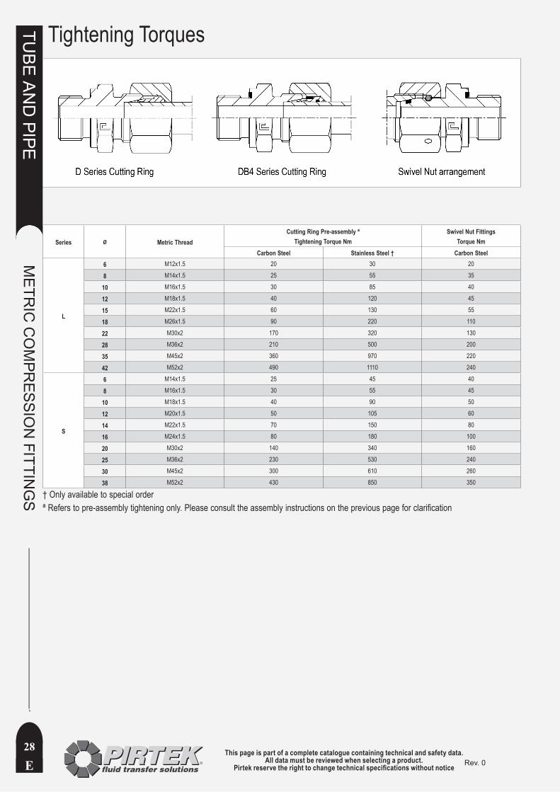
Tightening Torques
Series Ø Metric ThreadCutting Ring Pre-assembly ª
Tightening Torque NmSwivel Nut Fittings
Torque NmCarbon Steel Stainless Steel † Carbon Steel
L
6 M12x1.5 20 30 20
8 M14x1.5 25 55 35
10 M16x1.5 30 85 40
12 M18x1.5 40 120 45
15 M22x1.5 60 130 55
18 M26x1.5 90 220 110
22 M30x2 170 320 130
28 M36x2 210 500 200
35 M45x2 360 970 220
42 M52x2 490 1110 240
S
6 M14x1.5 25 45 40
8 M16x1.5 30 55 45
10 M18x1.5 40 90 50
12 M20x1.5 50 105 60
14 M22x1.5 70 150 80
16 M24x1.5 80 180 100
20 M30x2 140 340 160
25 M36x2 230 530 240
30 M45x2 300 610 260
38 M52x2 430 850 350
† Only available to special orderª Refers to pre-assembly tightening only. Please consult the assembly instructions on the previous page for clarification

This page is part of a complete catalogue containing technical and safety data.All data must be reviewed when selecting a product.
Pirtek reserve the right to change technical specifications without notice E
TUBE
AN
D PIPE
METR
IC C
OM
PRESSIO
N FITTIN
GS
29Rev. 0
NomenclatureThe metric compression part numbering adopted by Pirtek is a derivation of a commonly adopted International system. It’s basis is to be found within the German language, and is elaborated below to allow the interested reader to perhaps better understand the logic behind the Product Codes. Codes are aligned where possible with those used by Pirtek in Europe
Product Code German derivation English equivalentAS Anschweissen Weld on
BUZ Not derived from German Sometimes called VKA (German for Verschlusskegel-Adaptor or stopper cone)
D Doppel Double (also called DS for Doppel-Schneid or double cutting ring)
DB4 No direct derivation Used by Cast® to differentiate the elastomeric seal form of cutting ring
DSVW Drehschwenk-Verschraubung-Winkel Turn swivel screw together angle (Banjo coupling)
ED Elastomerisch-Dichtung Elastomeric seal (soft seal)
EZ E=elastomerisch (Z suggests Z series bonded seals) Elastomeric bonded seals for banjo type metric fittings DSVW
WD Weich-Dicthung Soft Seal
EDKO Elastomerisch-Dichtung-Konus Straight female joiner with elastomeric seals (konus = cone)
EDKOR Elastomerisch-Dichtung-Konus-Reduzierung Straight female reducing joiner with elastomeric seals (konus = cone)
EVGE Einstellbar-Gerade-Einschraubung Adjustable straight thread (Male stud coupling)
EVGER Einstellbar-Gerade-Einschraubung-Reduzierung Adjustable straight reducing thread (Male stud reducing coupling)
EVL Einstellbar-Verschraubung ‘L’ pattern Adjustable screw Tee with L configuration (adjustable barrel tee)
EVT Einstellbar-Verschraubung ‘T’ pattern Adjustable screw Tee with T configuration (adjustable branch tee)
EVW Einstellbar-Verschraubung-Winkel Adjustable screw elbow (adjustable elbow)
G Gerade Straight (Male Joiner)
GAI Gerade-Adapter-Innengewinde Straight adaptor with internal thread (female stud coupling)
GE Gerade-Einschrauben Straight screw in (male stud coupling)
GE-BSPP ED ED suffix (elastomerisch Dichtung) BSPP thread uses an elastomeric soft seal
GE-BSPP Form B Form B suffix BSPP thread uses a Form B type seal (see page E25)
GM Gegen-Mutter Against Nut (lock nut)
GSV Gerade-Schott-Verschraubung Straight bulkhead screw (straight bulkhead coupling)
GV Gerade-Verschraubung Straight threaded connection (reserved for reducing G series within Pirtek)
KOR Konus-Reduzieranschlusse Straight conical reducing connector (male female)
LE-BSPT L configuration Einschraub-Verschraubung L configuraion screw in BSPT threaded Tee (male stud barrel tee)
M Mutter Nut
MAV Manometer-Anschlussverschraubung Gauge connection screw thread (gauge coupling male thread)
MAVE Manometer-Anschlussverschraubung-Einstellbar Gauge connection adjustable screw thread (gauge coupling female thread)
NRV Ruckschlag-Ventile Non return valve
RI Reduziering-Innengewinde Reducing Bush
ROV Rohr-Verschluss Tube blanking plug
SKA Schweisskegel-Adapter Weld taper adaptor (weld nipple)
T Tee Equal Tee Coupling
TE-BSPT T configuration Einschraub-Verschraubung T configuraion screw in BSPT threaded Tee (male stud branch tee)
VSTI Verschlussschrauben Socket Head Port Plug (metric thread)
VSTIR R suffix Rohr (BSPP pipe thread)
W Winkel Elbow
WE-BSPT Winkel-Einschrauben Screw in elbow with BSPT thread
WSV Winkel-Schott-Verschraubung Elbow bulkhead threaded connection
‘k’ or ‘keg’ Suffix kegelig tapered
‘R’ Suffix Rohr BSPT pipe thread (the meaning changes in some contexts to reducing)
‘ED’ Suffix Elastomerisch-Dichtung Elastomeric seal (soft seal)
‘N’ or ‘NPT’ Suffix NPT NPT thread
‘G’ Suffix Gas BSPP thread
Metric tube sizes are expressed in millimetres using 2 digits in association with the tube weight eg 12L or 14S• Metric threads are expressed in the form M27x2 indicating thread diameter and pitch in millimetres• Imperial thread sizes are expressed as fractions of an inch (eg R1/4 or 1/2NPT) to avoid the use of Dash Sizes that may otherwise • resemble metric tube sizesTube weights are denoted as LL, L and S• LL = super light L = light (from the German ‘leicht’) S = heavy (from the German ‘schwer’)

This page is part of a complete catalogue containing technical and safety data.All data must be reviewed when selecting a product.
Pirtek reserve the right to change technical specifications without noticeE
TUBE
AN
D PIPE
METR
IC C
OM
PRESSIO
N FITTIN
GS
30Rev. 0
This page is intentionally blank

This page is part of a complete catalogue containing technical and safety data.All data must be reviewed when selecting a product.
Pirtek reserve the right to change technical specifications without notice E
TUBE
AN
D PIPE
METR
IC C
OM
PRESSIO
N FITTIN
GS
31Rev. 0
D Cutting Ring
DB4 Cutting Ring Soft Seal
Series Max. W.P. bar
Product Code Dimensions mmStandard
RingCutting Ring
Soft Seal ø Tube L1 D1 D2
LL 100D-04LL - 4 6 6 -
D-06LL - 6 7 8 -
D-08LL - 8 7 10 -
L
315
D-06L/S DB4-06L/S 6 9.5 10 10
D-08L/S DB4-08L/S 8 9.5 12 12
D-10L/S DB4-10L/S 10 10 14 14
D-12L/S DB4-12L/S 12 10 16 16
D-15L DB4-15L 15 10 19 20
D-18L DB4-18L† 18 10 23 23
160
D-22L DB4-22L† 22 10.5 27 27
D-28L DB4-28L† 28 11 33 33
D-35L DB4-35L† 35 13 41 41
D-42L DB4-42L† 42 13 48 48
S
630
D-06L/S DB4-06L/S 6 9.5 10 10
D-08L/S DB4-08L/S 8 9.5 12 12
D-10L/S DB4-10L/S 10 10 14 14
D-12L/S DB4-12L/S 12 10 16 16
D-14S DB4-14S 14 10 19 19
400
D-16S DB4-16S† 16 10.5 21 21
D-20S DB4-20S† 20 12 26 26
D-25S DB4-25S 25 12 32 32
D-30S DB4-30S 30 13 36 38
315 D-38S DB4-38S† 38 13 44 48
† Limited stock available
This page is part of a complete catalogue containing technical and safety data.All data must be reviewed when selecting a product.
Pirtek reserve the right to change technical specifications without noticeE
TUBE
AN
D PIPE
METR
IC C
OM
PRESSIO
N FITTIN
GS
32Rev. 0
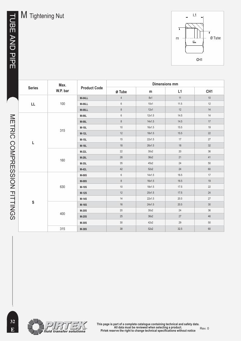
Series Max. W.P. bar Product Code
Dimensions mm
ø Tube m L1 CH1
LL 100M-04LL 4 8x1 11 10
M-06LL 6 10x1 11.5 12
M-08LL 8 12x1 12 14
L
315
M-06L 6 12x1.5 14.5 14
M-08L 8 14x1.5 14.5 17
M-10L 10 16x1.5 15.5 19
M-12L 12 18x1.5 15.5 22
M-15L 15 22x1.5 17 27
M-18L 18 26x1.5 18 32
160
M-22L 22 30x2 20 36
M-28L 28 36x2 21 41
M-35L 35 45x2 24 50
M-42L 42 52x2 24 60
S
630
M-06S 6 14x1.5 16.5 17
M-08S 8 16x1.5 16.5 19
M-10S 10 18x1.5 17.5 22
M-12S 12 20x1.5 17.5 24
M-14S 14 22x1.5 20.5 27
400
M-16S 16 24x1.5 20.5 30
M-20S 20 30x2 24 36
M-25S 25 36x2 27 46
M-30S 30 42x2 29 50
315 M-38S 38 52x2 32.5 60
M Tightening Nut

This page is part of a complete catalogue containing technical and safety data.All data must be reviewed when selecting a product.
Pirtek reserve the right to change technical specifications without notice E
TUBE
AN
D PIPE
METR
IC C
OM
PRESSIO
N FITTIN
GS
33Rev. 0
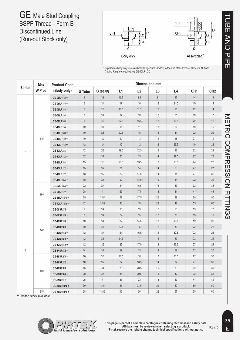
Series Max. W.P. bar
Product Code(Body only)
Dimensions mm
ø Tube P (NPT) L1 L2 L3 L4 CH1 CH2
LL 100GE-04LL1/8NPT † 4 1/8 - - - - - -
GE-08LL1/8NPT † 8 1/8 - - - - - -
L
315
GE-06L1/8NPT 6 1/8 14 7 10 22 12 14
GE-06L1/4NPT 6 1/4 15 8 15 22.5 14 14
GE-08L1/4NPT 8 1/4 15 8 15 23 17 17
GE-10L1/4NPT † 10 1/4 16 9 15 24 17 19
GE-10L3/8NPT 10 3/8 17 10 15 25 19 19
GE-12L1/4NPT † 12 1/4 17 10 15 24.5 19 22
GE-12L3/8NPT 12 3/8 17 10 15 24.5 19 22
GE-12L1/2NPT † 12 1/2 17.5 10.5 19.5 25 22 22
GE-15L1/2NPT 15 1/2 18.5 11.5 19.5 26.5 24 27
GE-18L1/2NPT 18 1/2 19.5 12 19.5 28.5 27 32
160
GE-22L3/4NPT † 22 3/4 21 13.5 20 30 32 36
GE-28L1NPT 28 1 22 14.5 25 31 41 41
GE-35L11/4NPT † 35 1.1/4 25.5 15 25.5 36.5 46 50
GE-42L11/2NPT 42 1.1/2 27 16 26 39 55 60
S
630
GE-06S1/4NPT 6 1/4 - - - - - -
GE-08S1/4NPT 8 1/4 20 13 15 28 17 19
GE-10S1/4NPT † 10 1/4 - - - - - -
GE-10S3/8NPT 10 3/8 20 12.5 15 28.5 19 22
GE-10S3/8NPT 10 3/8 20 12.5 15 28.5 19 22
GE-12S1/2NPT † 12 1/2 22.5 15 19.5 31 22 24
GE-12S3/8NPT 12 3/8 22 14.5 15 30.5 22 24
GE-14S1/2NPT † 14 1/2 24.5 16.5 19.5 34.5 24 27
400
GE-16S1/2NPT 16 1/2 24.5 16 19.5 34.5 27 30
GE-20S3/4NPT 20 3/4 28 17.5 20 39 32 36
GE-25S1NPT 25 1 32 20 25 44 41 46
GE-30S11/4NPT 30 1.1/4 34.5 21 25.5 47.5 46 50
315 GE-38S11/2NPT 38 1.1/2 39 23 26 54 55 60
† Limited stock available
GE Male Stud CouplingNPT Thread
Supplied as body only unless otherwise specified. Add ‘C’ to the end of the Product Code if a Nut and *Cutting Ring are required. eg GE-12L3/8NPTC
*

This page is part of a complete catalogue containing technical and safety data.All data must be reviewed when selecting a product.
Pirtek reserve the right to change technical specifications without noticeE
TUBE
AN
D PIPE
METR
IC C
OM
PRESSIO
N FITTIN
GS
34Rev. 0
GE Male Stud CouplingBSPT Thread
Series Max. W.P bar
Product Code(Body only)
Dimensions mm
ø Tube G (BSPT) L1 L2 L3 L4 CH1 CH2
L
315
GE-06LRK1/8 6 1/8 14 7 8 22 12 14
GE-08LRK1/4 8 1/4 15 8 12 23 17 17
GE-10LRK1/4 10 1/4 16 9 12 24 17 19
GE-10LRK3/8 † 10 3/8 17 10 12 25 19 19
GE-12LRK1/4 † 12 1/4 17 10 15 24.5 19 22
GE-12LRK3/8 12 3/8 17 10 12 24.5 19 22
GE-12LRK1/2 † 12 1/2 17 10 14 24.5 22 22
GE-15LRK1/2 15 1/2 18 11 14 26 24 27
GE-18LRK1/2 18 1/2 19 11.5 14 28 27 32
160
GE-22LRK3/4 † 22 3/4 21 13.5 16 30 32 36
GE-28LRK1 † 28 1 22 14.5 18 31 41 41
GE-35LRK11/4 † 35 1 1/4 25 14.5 20 36 46 50
GE-42LRK11/2 † 42 1 1/2 27 16 22 39 55 60
† Limited stock available
Supplied as body only unless otherwise specified. Add ‘C’ to the end of the Product Code if a Nut and *Cutting Ring are required. eg GE-12LRK3/8C
*
This page is part of a complete catalogue containing technical and safety data.All data must be reviewed when selecting a product.
Pirtek reserve the right to change technical specifications without notice E
TUBE
AN
D PIPE
METR
IC C
OM
PRESSIO
N FITTIN
GS
35Rev. 0
GE Male Stud CouplingBSPP Thread - Form BDiscontinued Line(Run-out Stock only)
Series Max. W.P bar
Product Code(Body only)
Dimensions mm
ø Tube G (BSPP) L1 L2 L3 L4 CH1 CH2
L
315
GE-06LR1/8 † 6 1/8 15.5 8.5 8 23 14 14
GE-06LR1/4 † 6 1/4 17 10 12 24.5 19 14
GE-06LR3/8 † 6 3/8 18.5 11.5 12 26 22 14
GE-08LR1/4 † 8 1/4 17 10 12 25 19 17
GE-08LR3/8 † 8 3/8 22.5 15.5 12 30.5 22 19
GE-10LR1/4 † 10 1/4 18 11 12 26 19 19
GE-10LR3/8 † 10 3/8 22.5 15 12 31 22 22
GE-10LR1/2 † 10 1/2 20 13 14 28 27 19
GE-12LR1/4 † 12 1/4 19 12 12 26.5 19 22
GE-12LR3/8 12 3/8 19.5 12.5 12 27 22 22
GE-12LR1/2 † 12 1/2 20 13 14 27.5 27 22
GE-15LR3/8 † 15 3/8 20.5 13.5 12 28.5 24 27
GE-15LR1/2 † 15 1/2 21 14 14 29 27 27
GE-18LR1/2 † 18 1/2 22 14.5 14 31 27 32
GE-18LR3/4 † 18 3/4 22 14.5 16 31 32 32
160
GE-22LR3/4 † 22 3/4 24 16.5 16 33 32 36
GE-28LR1 † 28 1 25 17.5 18 34 41 41
GE-35LR11/4 † 35 1.1/4 28 17.5 20 39 50 50
GE-42LR11/2 † 42 1.1/2 30 19 22 42 55 60
S
630
GE-06SR1/4 † 6 1/4 20 13 12 28 19 17
GE-08SR1/4 † 8 1/4 22 15 12 30 19 19
GE-10SR1/4 † 10 1/4 22 14.5 12 30.5 19 22
GE-10SR3/8 † 10 3/8 22.5 15 12 31 22 22
GE-12SR1/4 † 12 1/4 24 16.5 12 32.5 22 24
GE-12SR3/8 † 12 3/8 24.5 17 12 33 22 24
GE-12SR1/2 † 12 1/2 25 17.5 14 33.5 27 24
GE-14SR1/2 † 14 1/2 27 19 14 37 27 27
400
GE-16SR3/8 † 16 3/8 26.5 18 12 36.5 27 30
GE-16SR1/2 † 16 1/2 27 18.5 14 37 27 30
GE-16SR3/4 † 16 3/4 29 20.5 16 39 32 30
GE-20SR3/4 † 20 3/4 31 20.5 16 42 32 36
GE-25SR1 † 25 1 35 23 18 47 41 46
GE-30SR11/4 † 30 1.1/4 37 23.5 20 50 50 50
315 GE-38SR11/2 † 38 1.1/2 42 26 22 57 55 60† Limited stock available
Supplied as body only unless otherwise specified. Add ‘C’ to the end of the Product Code if a Nut and *Cutting Ring are required. eg GE-12LR1/2C
*
This page is part of a complete catalogue containing technical and safety data.All data must be reviewed when selecting a product.
Pirtek reserve the right to change technical specifications without noticeE
TUBE
AN
D PIPE
METR
IC C
OM
PRESSIO
N FITTIN
GS
36Rev. 0
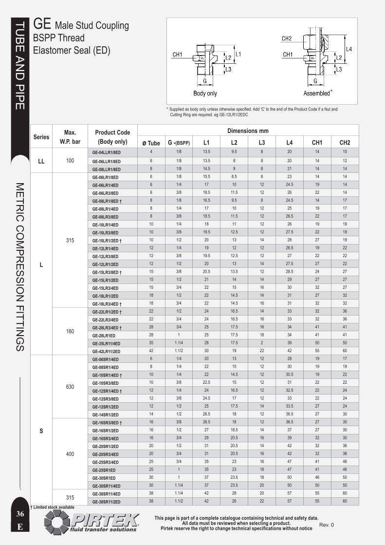
Series Max. W.P. bar
Product Code(Body only)
Dimensions mm
ø Tube G -(BSPP) L1 L2 L3 L4 CH1 CH2
LL 100GE-04LLR1/8ED 4 1/8 13.5 9.5 8 20 14 10
GE-06LLR1/8ED 6 1/8 13.5 8 8 20 14 12
GE-08LLR1/8ED 8 1/8 14.5 9 8 21 14 14
L
315
GE-06LR1/8ED 6 1/8 15.5 8.5 8 23 14 14
GE-06LR1/4ED 6 1/4 17 10 12 24.5 19 14
GE-06LR3/8ED 6 3/8 18.5 11.5 12 26 22 14
GE-08LR1/8ED † 8 1/8 16.5 9.5 8 24.5 14 17
GE-08LR1/4ED 8 1/4 17 10 12 25 19 17
GE-08LR3/8ED 8 3/8 18.5 11.5 12 26.5 22 17
GE-10LR1/4ED 10 1/4 18 11 12 26 19 19
GE-10LR3/8ED 10 3/8 19.5 12.5 12 27.5 22 19
GE-10LR1/2ED † 10 1/2 20 13 14 28 27 19
GE-12LR1/4ED 12 1/4 19 12 12 26.5 19 22
GE-12LR3/8ED 12 3/8 19.5 12.5 12 27 22 22
GE-12LR1/2ED 12 1/2 20 13 14 27.5 27 22
GE-15LR3/8ED † 15 3/8 20.5 13.5 12 28.5 24 27
GE-15LR1/2ED 15 1/2 21 14 14 29 27 27
GE-15LR3/4ED 15 3/4 22 15 16 30 32 27
GE-18LR1/2ED 18 1/2 22 14.5 14 31 27 32
GE-18LR3/4ED † 18 3/4 22 14.5 16 31 32 32
160
GE-22LR1/2ED † 22 1/2 24 16.5 14 33 32 36
GE-22LR3/4ED 22 3/4 24 16.5 16 33 32 36
GE-28LR3/4ED † 28 3/4 25 17.5 16 34 41 41
GE-28LR1ED 28 1 25 17.5 18 34 41 41
GE-35LR11/4ED 35 1.1/4 28 17.5 2 39 50 50
GE-42LR11/2ED 42 1.1/2 30 19 22 42 55 60
S
630
GE-06SR1/4ED 6 1/4 20 13 12 28 19 17
GE-08SR1/4ED 8 1/4 22 15 12 30 19 19
GE-10SR1/4ED † 10 1/4 22 14.5 12 30.5 19 22
GE-10SR3/8ED 10 3/8 22.5 15 12 31 22 22
GE-12SR1/4ED † 12 1/4 24 16.5 12 32.5 22 24
GE-12SR3/8ED 12 3/8 24.5 17 12 33 22 24
GE-12SR1/2ED 12 1/2 25 17.5 14 33.5 27 24
GE-14SR1/2ED 14 1/2 26.5 18 12 36.5 27 30
400
GE-16SR3/8ED † 16 3/8 26.5 18 12 36.5 27 30
GE-16SR1/2ED 16 1/2 27 18.5 14 37 27 30
GE-16SR3/4ED 16 3/4 29 20.5 16 39 32 30
GE-20SR1/2ED 20 1/2 31 20.5 14 42 32 36
GE-20SR3/4ED 20 3/4 31 20.5 16 42 32 36
GE-25SR3/4ED 25 3/4 35 23 16 47 41 46
GE-25SR1ED 25 1 35 23 18 47 41 46
GE-30SR1ED 30 1 37 23.5 18 50 46 50
GE-30SR11/4ED 30 1.1/4 37 23.5 20 50 50 50
315 GE-38SR11/4ED 38 1.1/4 42 26 20 57 55 60
GE-38SR11/2ED 38 1.1/2 42 26 22 57 55 60† Limited stock available
GE Male Stud CouplingBSPP ThreadElastomer Seal (ED)
Supplied as body only unless otherwise specified. Add ‘C’ to the end of the Product Code if a Nut and *Cutting Ring are required. eg GE-12LR1/2EDC
*
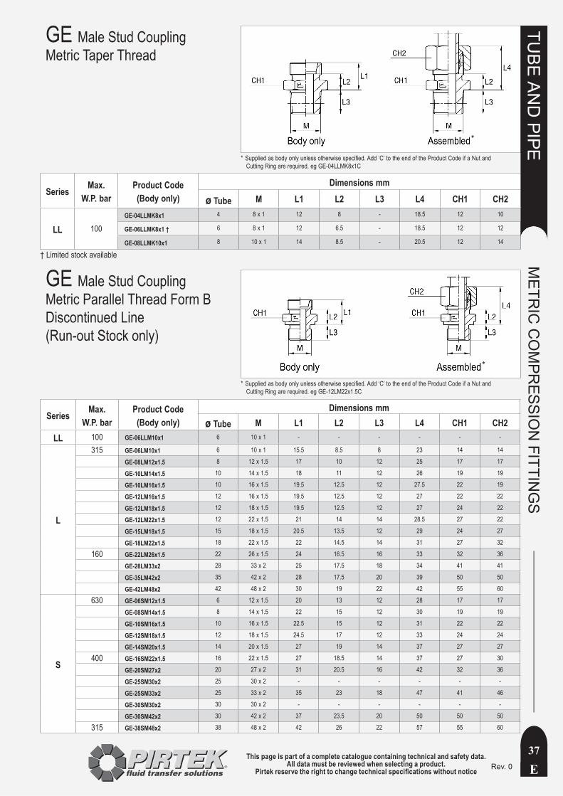
This page is part of a complete catalogue containing technical and safety data.All data must be reviewed when selecting a product.
Pirtek reserve the right to change technical specifications without notice E
TUBE
AN
D PIPE
METR
IC C
OM
PRESSIO
N FITTIN
GS
37Rev. 0
GE Male Stud CouplingMetric Taper Thread
Series Max. W.P. bar
Product Code(Body only)
Dimensions mm
ø Tube M L1 L2 L3 L4 CH1 CH2
LL 100GE-04LLMK8x1 4 8 x 1 12 8 - 18.5 12 10
GE-06LLMK8x1 † 6 8 x 1 12 6.5 - 18.5 12 12
GE-08LLMK10x1 8 10 x 1 14 8.5 - 20.5 12 14
† Limited stock available
GE Male Stud CouplingMetric Parallel Thread Form BDiscontinued Line(Run-out Stock only)
Series Max. W.P. bar
Product Code(Body only)
Dimensions mmø Tube M L1 L2 L3 L4 CH1 CH2
LL 100 GE-06LLM10x1 6 10 x 1 - - - - - -
L
315 GE-06LM10x1 6 10 x 1 15.5 8.5 8 23 14 14
GE-08LM12x1.5 8 12 x 1.5 17 10 12 25 17 17
GE-10LM14x1.5 10 14 x 1.5 18 11 12 26 19 19
GE-10LM16x1.5 10 16 x 1.5 19.5 12.5 12 27.5 22 19
GE-12LM16x1.5 12 16 x 1.5 19.5 12.5 12 27 22 22
GE-12LM18x1.5 12 18 x 1.5 19.5 12.5 12 27 24 22
GE-12LM22x1.5 12 22 x 1.5 21 14 14 28.5 27 22
GE-15LM18x1.5 15 18 x 1.5 20.5 13.5 12 29 24 27
GE-18LM22x1.5 18 22 x 1.5 22 14.5 14 31 27 32
160 GE-22LM26x1.5 22 26 x 1.5 24 16.5 16 33 32 36
GE-28LM33x2 28 33 x 2 25 17.5 18 34 41 41
GE-35LM42x2 35 42 x 2 28 17.5 20 39 50 50
GE-42LM48x2 42 48 x 2 30 19 22 42 55 60
S
630 GE-06SM12x1.5 6 12 x 1.5 20 13 12 28 17 17
GE-08SM14x1.5 8 14 x 1.5 22 15 12 30 19 19
GE-10SM16x1.5 10 16 x 1.5 22.5 15 12 31 22 22
GE-12SM18x1.5 12 18 x 1.5 24.5 17 12 33 24 24
GE-14SM20x1.5 14 20 x 1.5 27 19 14 37 27 27
400 GE-16SM22x1.5 16 22 x 1.5 27 18.5 14 37 27 30
GE-20SM27x2 20 27 x 2 31 20.5 16 42 32 36
GE-25SM30x2 25 30 x 2 - - - - - -
GE-25SM33x2 25 33 x 2 35 23 18 47 41 46
GE-30SM30x2 30 30 x 2 - - - - - -
GE-30SM42x2 30 42 x 2 37 23.5 20 50 50 50
315 GE-38SM48x2 38 48 x 2 42 26 22 57 55 60
Supplied as body only unless otherwise specified. Add ‘C’ to the end of the Product Code if a Nut and *Cutting Ring are required. eg GE-04LLMK8x1C
*
Supplied as body only unless otherwise specified. Add ‘C’ to the end of the Product Code if a Nut and *Cutting Ring are required. eg GE-12LM22x1.5C
*

This page is part of a complete catalogue containing technical and safety data.All data must be reviewed when selecting a product.
Pirtek reserve the right to change technical specifications without noticeE
TUBE
AN
D PIPE
METR
IC C
OM
PRESSIO
N FITTIN
GS
38Rev. 1
GE Male Stud CouplingMetric Parallel ThreadElastomer Seal (ED)
Series Max. W.P. bar
Product Code(Body only)
Dimensions mmø Tube W D1 L1 L2 L3 L4 CH1 CH2
L 315
GE-12L9/16UNF 12 9/16 - 18 18.8 18 11 10 25.5 19 22
GE-12L3/4UNF 12 3/6 - 16 21.8 19.9 12.9 11.1 27.5 22 22
GE-12L7/8UNF 12 7/8 - 14 26.8 21.3 14.3 12.7 29 27 22
GE-18L3/4UNF 18 3/4 - 16 21.8 21.9 14.4 11.1 31 27 32
S 400
GE-16S3/4UNF 16 3/4 - 16 21.8 23.9 15.4 11.1 34 27 30
GE-16S7/8UNF 16 7/8 - 14 26.8 27.3 18.8 12.7 37.5 27 30
GE-20S3/4UNF 20 3/4 - 16 21.8 30.9 20.4 11.1 42 32 36
GE-20S7/8UNF 20 7/8 - 14 26.8 31.3 20.8 12.7 42.5 32 36
GE-20S11/16UNF 20 1.1/16 - 12 31.8 30.9 20.4 15.1 42 32 36
GE Male Stud CouplingUN-O Thread
Supplied as body only unless otherwise specified. Add ‘C’ to the end of the Product Code if a Nut and *Cutting Ring are required. eg GE-15LM18x1.5EDC
Supplied as body only unless otherwise specified. Add ‘C’ to the end of the Product Code *if a Nut and Cutting Ring are required. eg GE-18L3/4UNFC
*
*
Series Max. W.P. bar
Product Code(Body only)
Dimensions mm
ø Tube M L1 L2 L3 L4 CH1 CH2
LL 100 GE-04LLM8X1ED 4 8 x 1 13.5 9.5 8 20 12 10
GE-08LLM10X1ED 8 10 x 1 14.5 9 8 21 14 14
L
315
GE-06LM10x1ED 6 10 x 1 15.5 8.5 8 23 14 14
GE-08LM12x1.5ED 8 12 x 1.5 17 10 12 25 17 17
GE-10LM14x1.5ED 10 14 x 1.5 18 11 12 26 19 19
GE-12LM16x1.5ED 12 16 x 1.5 19.5 12.5 12 27 22 22
GE-15LM18x1.5ED 15 18 x 1.5 20.5 13.5 12 29 24 27
GE-18LM22x1.5ED 18 22 x 1.5 22 14.5 14 31 27 32
160
GE-22LM26x1.5ED 22 26 x 1.5 24 16.5 16 33 32 36
GE-28LM33x2ED 28 33 x 2 25 17.5 18 34 41 41
GE-35LM42x2ED 35 42 x 2 28 17.5 20 39 50 50
GE-42LM48x2ED 42 48 x 2 30 19 22 42 55 60
S
630
GE-06SM12x1.5ED 6 12 x 1.5 20 13 12 28 17 17
GE-08SM14x1.5ED 8 14 x 1.5 22 15 12 30 19 19
GE-10SM16x1.5ED 10 16 x 1.5 22.5 15 12 31 22 22
GE-12SM18x1.5ED 12 18 x 1.5 24.5 17 12 33 24 24
GE-14SM20x1.5ED 14 20 x 1.5 27 19 14 37 27 27
400
GE-16SM22x1.5ED 16 22 x 1.5 27 18.5 14 37 27 30
GE-20SM27x2ED 20 27 x 2 31 20.5 16 42 32 36
GE-25SM33x2ED 25 33 x2 35 23 18 47 41 46
GE-30SM42x2ED 30 42 x 2 37 23.5 20 50 50 50
315 GE-38SM48x2ED † 38 48 x 2 42 36 22 57 55 60
† Limited stock available

This page is part of a complete catalogue containing technical and safety data.All data must be reviewed when selecting a product.
Pirtek reserve the right to change technical specifications without notice E
TUBE
AN
D PIPE
METR
IC C
OM
PRESSIO
N FITTIN
GS
39Rev. 0
Series Max. W.P. bar
Product Code (Body only)
Dimensions mmø Tube L1 L2 L3 CH1 CH2
LL 100G-04LL † 4 20 12 31 12 10
G-06LL 6 20 9 32 12 12
G-08LL 8 23 12 35 12 14
L
315
G-06L 6 24 10 39 12 14
G-08L 8 25 11 40 14 17
G-10L 10 27 13 42 17 19
G-12L 12 28 14 43 19 22
G-15L 15 30 16 46 24 27
G-18L 18 31 16 48 27 32
160
G-22L 22 35 20 52 32 36
G-28L 28 36 21 54 41 41
G-35L 35 41 20 63 46 50
G-42L 42 43 21 66 55 60
S
630
G-06S 6 30 16 45 14 17
G-08S 8 32 18 47 17 19
G-10S 10 32 17 49 19 22
G-12S 12 34 19 51 22 24
G-14S 14 38 22 57 24 27
400
G-16S 16 38 21 57 27 30
G-20S 20 44 23 66 32 36
G-25S 25 50 26 74 41 46
G-30S 30 54 27 80 46 50
315 G-38S 38 61 29 90 55 60
† Limited stock available
G Straight Tube Coupling
Supplied as body only unless otherwise specified. Add ‘C’ to the end of the Product Code if Nuts and *Cutting Rings are required. eg G-12LC
*
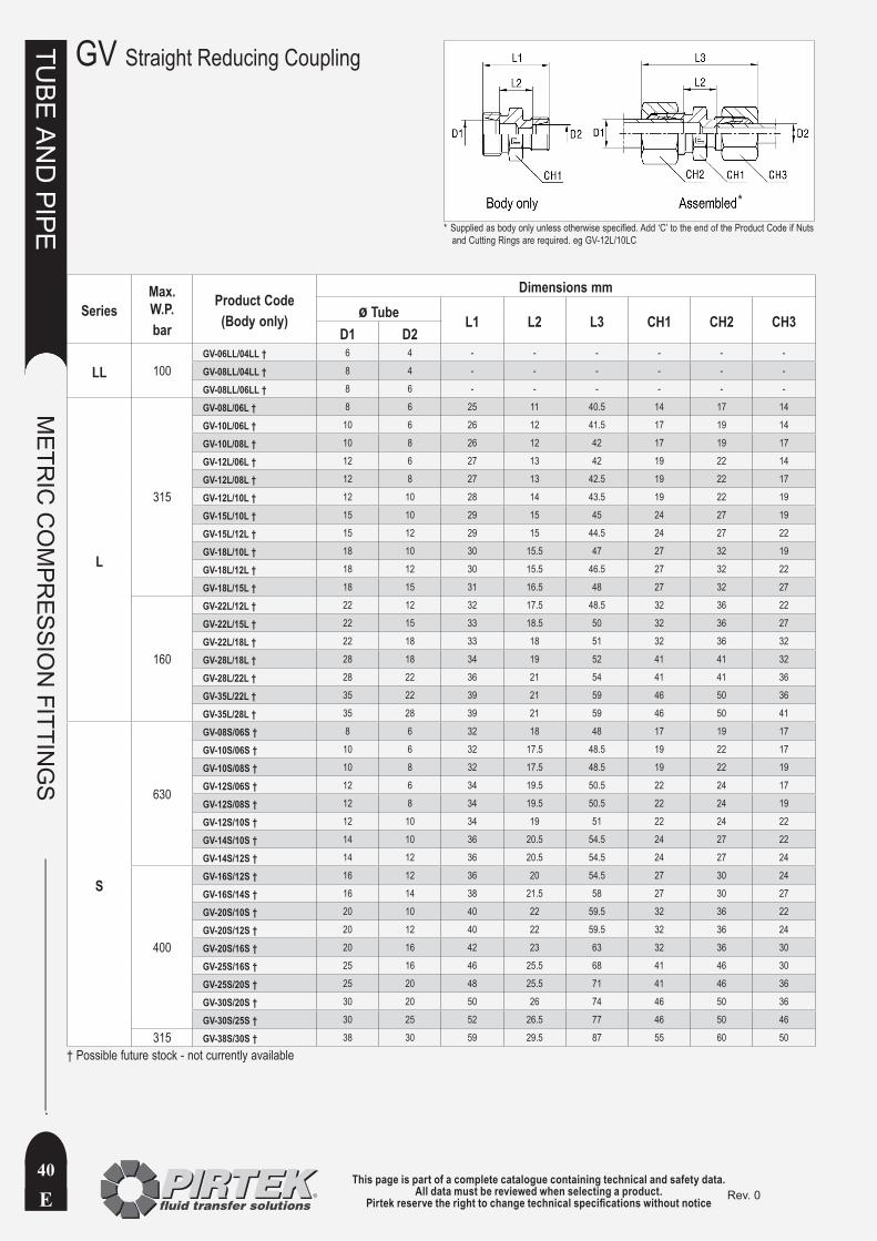
This page is part of a complete catalogue containing technical and safety data.All data must be reviewed when selecting a product.
Pirtek reserve the right to change technical specifications without noticeE
TUBE
AN
D PIPE
METR
IC C
OM
PRESSIO
N FITTIN
GS
40Rev. 0
GV Straight Reducing Coupling
SeriesMax. W.P. bar
Product Code(Body only)
Dimensions mmø Tube L1 L2 L3 CH1 CH2 CH3
D1 D2
LL 100GV-06LL/04LL † 6 4 - - - - - -
GV-08LL/04LL † 8 4 - - - - - -
GV-08LL/06LL † 8 6 - - - - - -
L
315
GV-08L/06L † 8 6 25 11 40.5 14 17 14
GV-10L/06L † 10 6 26 12 41.5 17 19 14
GV-10L/08L † 10 8 26 12 42 17 19 17
GV-12L/06L † 12 6 27 13 42 19 22 14
GV-12L/08L † 12 8 27 13 42.5 19 22 17
GV-12L/10L † 12 10 28 14 43.5 19 22 19
GV-15L/10L † 15 10 29 15 45 24 27 19
GV-15L/12L † 15 12 29 15 44.5 24 27 22
GV-18L/10L † 18 10 30 15.5 47 27 32 19
GV-18L/12L † 18 12 30 15.5 46.5 27 32 22
GV-18L/15L † 18 15 31 16.5 48 27 32 27
160
GV-22L/12L † 22 12 32 17.5 48.5 32 36 22
GV-22L/15L † 22 15 33 18.5 50 32 36 27
GV-22L/18L † 22 18 33 18 51 32 36 32
GV-28L/18L † 28 18 34 19 52 41 41 32
GV-28L/22L † 28 22 36 21 54 41 41 36
GV-35L/22L † 35 22 39 21 59 46 50 36
GV-35L/28L † 35 28 39 21 59 46 50 41
S
630
GV-08S/06S † 8 6 32 18 48 17 19 17
GV-10S/06S † 10 6 32 17.5 48.5 19 22 17
GV-10S/08S † 10 8 32 17.5 48.5 19 22 19
GV-12S/06S † 12 6 34 19.5 50.5 22 24 17
GV-12S/08S † 12 8 34 19.5 50.5 22 24 19
GV-12S/10S † 12 10 34 19 51 22 24 22
GV-14S/10S † 14 10 36 20.5 54.5 24 27 22
GV-14S/12S † 14 12 36 20.5 54.5 24 27 24
400
GV-16S/12S † 16 12 36 20 54.5 27 30 24
GV-16S/14S † 16 14 38 21.5 58 27 30 27
GV-20S/10S † 20 10 40 22 59.5 32 36 22
GV-20S/12S † 20 12 40 22 59.5 32 36 24
GV-20S/16S † 20 16 42 23 63 32 36 30
GV-25S/16S † 25 16 46 25.5 68 41 46 30
GV-25S/20S † 25 20 48 25.5 71 41 46 36
GV-30S/20S † 30 20 50 26 74 46 50 36
GV-30S/25S † 30 25 52 26.5 77 46 50 46
315 GV-38S/30S † 38 30 59 29.5 87 55 60 50
† Possible future stock - not currently available
Supplied as body only unless otherwise specified. Add ‘C’ to the end of the Product Code if Nuts *and Cutting Rings are required. eg GV-12L/10LC
*
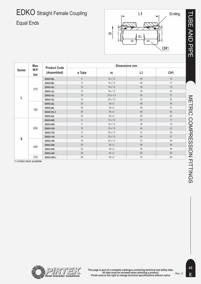
This page is part of a complete catalogue containing technical and safety data.All data must be reviewed when selecting a product.
Pirtek reserve the right to change technical specifications without notice E
TUBE
AN
D PIPE
METR
IC C
OM
PRESSIO
N FITTIN
GS
41Rev. 0
EDKO Straight Female Coupling
Equal Ends
SeriesMax. W.P. bar
Product Code(Assembled)
Dimensions mm
ø Tube m L1 CH1
L
315
EDKO-06L 6 12 x 1.5 40 14
EDKO-08L 8 14 x 1.5 40 17
EDKO-10L 10 16 x 1.5 39 19
EDKO-12L 12 18 x 1.5 39 22
EDKO-15L 15 212 x 1.5 45 27
EDKO-18L 18 26 x 1.5 43 32
160
EDKO-22L 22 30 x 2 48 36
EDKO-28L 28 36 x 2 49 41
EDKO-35L † 35 45 x 2 60 50
EDKO-42L 42 52 x 2 60 60
S
630
EDKO-06S 6 14 x 1.5 37 17
EDKO-08S 8 16 x 1.5 38 19
EDKO-10S 10 18 x 1.5 44 22
EDKO-12S 12 20 x 1.5 41 24
EDKO-14S 14 22 x 1.5 44 27
400
EDKO-16S 16 24 x 1.5 51 30
EDKO-20S 20 30 x 2 56 36
EDKO-25S 25 36 x 2 60 46
EDKO-30S 30 42 x 2 62 50
315 EDKO-38S † 38 52 x 2 70 60
† Limited stock available
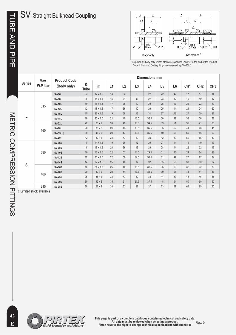
This page is part of a complete catalogue containing technical and safety data.All data must be reviewed when selecting a product.
Pirtek reserve the right to change technical specifications without noticeE
TUBE
AN
D PIPE
METR
IC C
OM
PRESSIO
N FITTIN
GS
42Rev. 0
SV Straight Bulkhead Coupling
Series Max. W.P. bar
Product Code(Body only)
Dimensions mmø
Tube m L1 L2 L3 L4 L5 L6 CH1 CH2 CH3
L
315
SV-06L 6 12 x 1.5 14 34 7 27 22 42 17 17 14
SV-08L 8 14 x 1.5 15 34 8 27 23 42 19 19 17
SV-10L 10 16 x 1.5 17 35 10 28 25 43 22 22 19
SV-12L 12 18 x 1.5 17 36 10 29 25 44 24 24 22
SV-15L 15 22 x 1.5 19 38 12 31 27 46 27 30 27
SV-18L 18 26 x 1.5 21 40 13.5 32.5 30 49 32 36 32
160
SV-22L 22 30 x 2 24 42 16.5 34.5 33 51 36 41 36
SV-28L 28 36 x 2 26 43 18.5 35.5 35 52 41 46 41
SV-35L † 35 45 x 2 29 47 18.5 36.6 40 58 50 55 50
SV-42L 42 52 x 2 30 47 19 36 42 59 60 65 60
S
630
SV-06S 6 14 x 1.5 19 36 12 29 27 44 19 19 17
SV-08S 8 16 x 1.5 20 36 13 29 28 44 22 22 19
SV-10S 10 18 x 1.5 22 37 14.5 29.5 31 46 24 24 22
SV-12S 12 20 x 1.5 22 38 14.5 30.5 31 47 27 27 24
SV-14S 14 22 x 1.5 25 40 17 32 35 50 30 30 27
400
SV-16S 16 24 x 1.5 25 40 16.5 31.5 35 50 32 32 30
SV-20S 20 30 x 2 28 44 17.5 33.5 39 55 41 41 36
SV-25S 25 36 x 2 32 47 20 35 44 59 46 46 46
SV-30S 30 42 x 2 35 51 21.5 37.5 48 64 50 50 50
315 SV-38S 38 52 x 2 38 53 22 37 53 68 65 65 60
† Limited stock available
Supplied as body only unless otherwise specified. Add ‘C’ to the end of the Product *Code if Nuts and Cutting Rings are required. eg SV-15LC
*

This page is part of a complete catalogue containing technical and safety data.All data must be reviewed when selecting a product.
Pirtek reserve the right to change technical specifications without notice E
TUBE
AN
D PIPE
METR
IC C
OM
PRESSIO
N FITTIN
GS
43Rev. 0
AS Welding Boss
SeriesMax. W.P. Bar
Product Code (Body only)
Dimensions mm
ø Tube D1 L1 L2 L3 CH1 CH2
L
315
AS-06L † 6 10 14 21 29 12 14
AS-08L 8 12 16 23 31 14 17
AS-10L † 10 14 18 25 33 17 19
AS-12L † 12 16 18 25 33 19 22
AS-15L † 15 19 22 29 37 22 27
AS-18L 18 22 23.5 31 40 27 32
160
AS-22L † 22 27 28.5 36 45 32 36
AS-28L † 28 32 30.5 38 47 41 41
AS-35L † 35 40 32.5 43 54 46 50
AS-42L † 42 46 35 46 58 55 60
S
630
AS-06S 6 11 19 26 34 14 17
AS-08S 8 13 21 28 36 17 19
AS-10S 10 15 22.5 30 39 19 22
AS-12S 12 17 24.5 32 41 22 24
AS-14S † 14 19 27 35 45 24 27
400
AS-16S 16 21 26.5 35 45 27 30
AS-20S 20 26 29.5 40 51 32 36
AS-25S 25 31 32 44 56 41 46
AS-30S 30 36 35.5 49 62 46 50
315 AS-38S 38 44 38 54 69 55 60
† Limited stock available
Supplied as body only unless otherwise specified. Add ‘C’ to the end of the Product *Code if a Nut and Cutting Ring are required. eg AS-18LC
*

This page is part of a complete catalogue containing technical and safety data.All data must be reviewed when selecting a product.
Pirtek reserve the right to change technical specifications without noticeE
TUBE
AN
D PIPE
METR
IC C
OM
PRESSIO
N FITTIN
GS
44Rev. 0
Series Max.W.P. bar
Product Code (Nipple only)
Dimensions mmø x Wall
Thickness ø Tube D1 D2 L1
L / S
- SKA6x1 † 6x1 6 - - -
630 SKA6x1.75 † 6x1.75 6 2.5 6 31
SKA8x1.5 † 8x1.5 8 - - -
630 SKA8x2 † 8x2 8 4 8 31
315 SKA10X1.5 † 10X1.5 10 7 10 32.5
315 SKA12X1.5 † 12X1.5 12 9 12 32.5
- SKA18x2 † 18x2 18 - - -
- SKA22x2 † 22x2 22 - - -
L
- SKA15x1.5 † 15x1.5 15 - - -
315 SKA15x2.5 † 15x2.5 15 10 15 34
315 SKA18x2.5 † 18x2.5 18 13 18 35.5
160 SKA22x2.5 † 22x2.5 22 17 22 38.5
160 SKA28X2.5 † 28X2.5 28 23 28 41.5
160 SKA35X3 † 35X3 35 29 35 47.5
S
- SKA14X2 † 14X2 14 - - -
400 SKA14X3 † 14X3 14 8 14 38.5
250 SKA16X2 16X2 16 12 16 39
250 SKA20X2.5 20X2.5 20 15 20 45
315 SKA20X3 † 20X3 20 14 20 45
- SKA25X2.5 † 25X2.5 25 - - -
250 SKA25X3 † 25X3 25 19 25 49.5
160 SKA30X3 30X3 30 24 30 52
250 SKA38X5 † 38X5 38 - - -
315 SKA38X6 † 38X6 38 26 38 56.5
† Limited stock available
SKA Welding Nipple
* Supplied disassembled
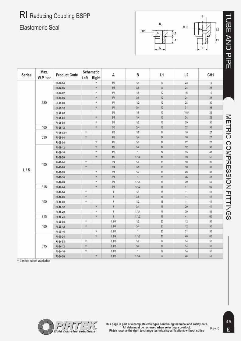
This page is part of a complete catalogue containing technical and safety data.All data must be reviewed when selecting a product.
Pirtek reserve the right to change technical specifications without notice E
TUBE
AN
D PIPE
METR
IC C
OM
PRESSIO
N FITTIN
GS
45Rev. 0
RI Reducing Coupling BSPP
Elastomeric Seal
Series Max.W.P. bar Product Code Schematic
Left Right A B L1 L2 CH1
L / S
630
RI-02-04 * 1/8 1/4 8 23 19
RI-02-06 * 1/8 3/8 8 24 24
RI-04-02 * 1/4 1/8 12 16 19
RI-04-06 * 1/4 3/8 12 24 24
RI-04-08 * 1/4 1/2 12 28 30
RI-04-12 * 1/4 3/4 12 31 36
RI-06-02 3/8 1/8 12 10.5 22
RI-06-04 * 3/8 1/4 12 24 22
RI-06-08 * 3/8 1/2 12 29 30
400 RI-06-12 * 3/8 3/4 12 32 36
630RI-08-02 † * 1/2 1/8 14 10 27
RI-08-04 * 1/2 1/4 14 10 27
RI-08-06 * 1/2 3/8 14 22 27
400
RI-08-12 * 1/2 3/4 14 32 36
RI-08-16 * 1/2 1 14 35 41
RI-08-20 * 1/2 1.1/4 14 39 55
RI-12-04 * 3/4 1/4 16 10 32
RI-12-06 * 3/4 3/8 16 10 32
RI-12-08 * 3/4 1/2 16 26 32
RI-12-16 * 3/4 1 16 35 41
RI-12-20 * 3/4 1.1/4 16 39 55
315 RI-12-24 * 3/4 1/1/2 16 41 60
400
RI-16-04 * 1 1/4 18 11 41
RI-16-06 * 1 3/8 18 11 41
RI-16-08 * 1 1/2 18 11 41
RI-16-12 * 1 3/4 18 29 41
RI-16-20 * 1 1.1/4 18 39 55
315 RI-16-24 * 1 1.1/2 18 41 60
400RI-20-08 * 1.1/4 1/2 20 12 50
RI-20-12 * 1.1/4 3/4 20 12 50
RI-20-16 * 1.1/4 1 20 31 50
315
RI-20-24 * 1.1/4 1.1/2 20 40 60
RI-24-08 * 1.1/2 1/2 22 14 55
RI-24-12 * 1.1/2 3/4 22 14 55
RI-24-16- * 1.1/2 1 22 14 55
RI-24-20 * 1.1/2 1.1/4 22 46 50† Limited stock available

This page is part of a complete catalogue containing technical and safety data.All data must be reviewed when selecting a product.
Pirtek reserve the right to change technical specifications without noticeE
TUBE
AN
D PIPE
METR
IC C
OM
PRESSIO
N FITTIN
GS
46Rev. 0
EVGER Male Stud Standpipe - MetricElastomer Seal (ED)Discontinued Line(Run-out Stock only)
Series Max. W.P. bar
Product Code (Body only)
Dimensions mmø Tube m M L1 L2 CH1 CH2
L
315
EVGER-06LM10x1ED 6 12 x 1.5 10 x 1 24.5 8 14 14
EVGER-08LM12x1.5ED 8 14 x 1.5 12 x 1.5 26.5 12 17 17
EVGER-10LM14x1.5ED 10 16 x 1.5 14 x 1.5 27.5 12 19 19
EVGER-12LM16x1.5ED 12 18 x 1.5 16 x 1.5 30.5 12 22 22
EVGER-15L182x1.5ED 15 22 x 1.5 18 x 1.5 31.5 12 24 27
EVGER-18LM22x1.5ED 18 26 x 1.5 22 x 1.5 31.5 14 27 32
160
EVGER-22LM26x1.5ED 22 30 x 2 26 x 1.5 32.5 16 32 36
EVGER-28LM33x2ED † 28 36 x 2 33 x 2 35 18 41 41
EVGER-35LM42x2ED † 35 45 x 2 42 x 2 42.5 20 50 50
EVGER-42LM48x2ED 42 52 x 2 48 x 2 46.5 22 55 60
S
630
EVGER-06SM12x1.5ED 6 14 x 1.5 12 x 1.5 27 12 17 17
EVGER-08SM14x1.5ED 8 16 x 1.5 14 x 1.5 29.5 12 19 19
EVGER-10SM16x1.5ED 10 18 x 1.5 16 x 1.5 32 12 22 22
EVGER-12SM18x1.5ED 12 20 x 1.5 18 x 1.5 34 12 24 24
EVGER-14SM20x1.5ED 14 22 x 1.5 20 x 1.5 36.5 14 27 27
400
EVGER-16SM22x1.5ED 16 24 x 1.5 22 x 1.5 37 14 27 30
EVGER-20SM27x2ED 20 30 x 2 27 x 2 43 16 32 36
EVGER-25SM33x2ED 25 36 x 2 33 x 2 48 18 41 46
EVGER-30SM42x2ED † 30 42 x 2 42 x 2 51 20 50 50
315 EVGER-38SM48x2ED 38 52 x 2 48 x 2 60 22 55 60
† Limited stock available
Supplied as body only unless otherwise specified. Add ‘C’ to the *end of the Product Code if a Nut and Cutting Ring are required. eg EVGER-18LM22x1.5EDC
*

This page is part of a complete catalogue containing technical and safety data.All data must be reviewed when selecting a product.
Pirtek reserve the right to change technical specifications without notice E
TUBE
AN
D PIPE
METR
IC C
OM
PRESSIO
N FITTIN
GS
47Rev. 0
EVGE Male Stud Coupling with Swivel Nut - Metric / BSPPElastomer Seal (ED)
Series Max. W.P. bar
Product Code (Body only)
Dimensions mmø Tube m M L1 L2 CH1 CH2
L
315
EVGE-06LM12x1.5ED † 6 12 x 1.5 10 x 1 24.5 8 14 14
EVGE-08LM14x1.5ED † 8 14 x 1.5 12 x 1.5 26.5 12 17 17
EVGE-10LM16x1.5ED † 10 16 x 1.5 14 x 1.5 27.5 12 19 19
EVGE-12LM18x1.5ED † 12 18 x 1.5 16 x 1.5 30.5 12 22 22
EVGE-15LM22x1.5ED † 15 22 x 1.5 18 x 1.5 31.5 12 24 27
EVGE-18LM26x1.5ED † 18 26 x 1.5 22 x 1.5 31.5 14 27 32
160
EVGE-22LM30x2ED † 22 30 x 2 26 x 1.5 32.5 16 32 36
EVGE-28LM36x2ED † 28 36 x 2 33 x 2 35 18 41 41
EVGE-35LM45x2ED † 35 45 x 2 42 x 2 42.5 20 50 50
EVGE-42LM52x2ED † 42 52 x 2 48 x 2 46.5 22 55 60
S
630
EVGE-06SM14x1.5ED † 6 14 x 1.5 12 x 1.5 27 12 17 17
EVGE-08SM16x1.5ED † 8 16 x 1.5 14 x 1.5 29.5 12 19 19
EVGE-10SM18x1.5ED † 10 18 x 1.5 16 x 1.5 32 12 22 22
EVGE-12SM20x1.5ED † 12 20 x 1.5 18 x 1.5 34 12 24 24
EVGE-14SM22x1.5ED † 14 22 x 1.5 20 x 1.5 36.5 14 27 27
400
EVGE-16SM24x1.5ED † 16 24 x 1.5 22 x 1.5 37 14 27 30
EVGE-20SM30x2ED † 20 30 x 2 27 x 2 43 16 32 36
EVGE-25SM36x2ED † 25 36 x 2 33 x 2 48 18 41 46
EVGE-30SM42x2ED † 30 42 x 2 42 x 2 51 20 50 50
315 EVGE-38SM52x2ED 38 52 x 2 48 x 2 60 22 55 60
Series Max. W.P. bar
Product Code (Body only)
Dimensions mm (except G)ø Tube m G (ins) L1 L2 CH1 CH2
L
315
EVGE-06LR1/8ED 6 12 x 1.5 1/8 24.5 8 14 14
EVGE-08LR1/4ED 8 14 x 1.5 1/4 29.5 12 19 17
EVGE-10LR1/4ED 10 16 x 1.5 1/4 27.5 12 19 19
EVGE-12LR3/8ED 12 18 x 1.5 3/8 34 12 22 22
EVGE-15LR1/2ED 15 22 x 1.5 1/2 32 14 27 27
EVGE-18LR1/2ED 18 26 x 1.5 1/2 31.5 14 27 32
160
EVGE-22LR3/4ED 22 30 x 2 3/4 32.5 16 32 36
EVGE-28LR1ED 28 36 x 2 1 35 18 41 41
EVGE-35LR11/4ED † 35 45 x 2 1.1/4 42.5 20 50 50
EVGE-42LR11/2ED 42 52 x 2 1.1/2 46.5 22 55 60
S
630
EVGE-06SR1/4ED 6 14 x 1.5 1/4 27 12 19 17
EVGE-08SR1/4ED 8 16 x 1.5 1/4 29.5 12 19 19
EVGE-10SR3/8ED 10 18 x 1.5 3/8 32 12 22 22
EVGE-12SR3/8ED 12 20 x 1.5 3/8 34 12 22 24
EVGE-14SR1/2ED 14 22 x 1.5 1/2 36.5 14 27 27
400
EVGE-16SR1/2ED 16 24 x 1.5 1/2 37 14 27 30
EVGE-20SR3/4ED 20 30 x 2 3/4 43 16 32 36
EVGE-25SR1ED 25 36 x 2 1 48 18 41 46
EVGE-30SR11/4ED 30 42 x 2 1.1/4 51 20 50 50
315 EVGE-38SR11/2ED 38 52 x 2 1.1/2 60 22 55 60
† Limited stock available
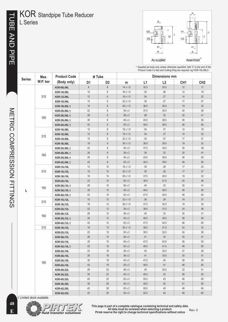
This page is part of a complete catalogue containing technical and safety data.All data must be reviewed when selecting a product.
Pirtek reserve the right to change technical specifications without noticeE
TUBE
AN
D PIPE
METR
IC C
OM
PRESSIO
N FITTIN
GS
48Rev. 0
KOR Standpipe Tube ReducerL Series
Series Max. W.P. bar
Product Code (Body only)
ø Tube Dimensions mmD1 D2 m L1 L2 CH1 CH2
L
315
KOR-08L/06L 8 6 14 x 1.5 32.5 25.5 12 17
KOR-10L/06L 10 6 16 x 1.5 33 26 12 19
KOR-12L/06L 12 6 18 x 1.5 34 27 14 22
KOR-15L/06L 15 6 22 x 1.5 34 27 17 27
KOR-18L/06L † 18 6 26 x 1.5 36.5 29.5 19 32
160
KOR-22L/06L † 22 6 30 x 2 37.5 30.5 24 36
KOR-28L/06L † 28 6 36 x 2 39 32 30 41
KOR-35L/06L † 35 6 45 x 2 45.5 38.5 36 50
KOR-42L/06L † 42 6 52 x 2 46.5 39.5 46 60
315
KOR-10L/08L 10 8 16 x 1.5 34 27 14 19
KOR-12L/08L 12 8 18 x 1.5 34 27 14 22
KOR-15L/08L 15 8 22 x 1.5 34 27 17 27
KOR-18L/08L 18 8 26 x 1.5 36.5 29.5 19 32
160
KOR-22L/08L † 22 8 30 x 2 37.5 30.5 34 36
KOR-28L/08L † 28 8 36 x 2 39 32 30 41
KOR-35L/08L † 35 8 45 x 2 45.5 38.5 36 50
KOR-42L/08L † 42 8 52 x 2 46.5 39.5 46 60
315KOR-12L/10L 12 10 18 x 1.5 35 28 17 22
KOR-15L/10L 15 10 22 x 1.5 35 28 17 27
KOR-18L/10L 18 10 26 x 1.5 37.5 30.5 19 32
160
KOR-22L/10L 22 10 30 x 2 38.5 31.5 24 36
KOR-28L/10L † 28 10 36 x 2 40 33 30 41
KOR-35L/10L † 35 10 45 x 2 46.5 39.5 36 50
KOR-42L/10L † 42 10 52 x 2 47.5 40.5 46 60
315 KOR-15L/12L 15 12 22 x 1.5 36 29 19 27
KOR-18L/12L 18 12 26 x 1.5 37.5 30.5 19 32
160
KOR-22L/12L 22 12 30 x 2 38.5 31.5 24 36
KOR-28L/12L 28 12 36 x 2 40 33 30 41
KOR-35L/12L † 35 12 45 x 2 46.5 39.5 36 50
KOR-42L/12L † 42 12 52 x 2 47.5 40.5 46 60
315 KOR-18L/15L 18 15 26 x 1.5 38.5 31.5 24 32
160
KOR-22L/15L 22 15 30 x 2 39.5 32.5 24 36
KOR-28L/15L 28 15 36 x 2 41 34 30 41
KOR-35L/15L 35 15 45 x 2 47.5 40.5 36 50
KOR-42L/15L † 42 15 52 x 2 48.5 41.5 46 60
KOR-22L/18L 22 18 30 x 2 40 32.5 27 36
KOR-28L/18L 28 18 36 x 2 41 33.5 30 41
KOR-35L/18L 35 18 45 x 2 47.5 40 36 50
KOR-42L/18L 42 18 52 x 2 48.5 41 46 60
KOR-28L/22L 28 22 36 x 2 43 35.5 32 41
KOR-35L/22L 35 22 45 x 2 49.5 42 36 50
KOR-42L/22L 42 22 52 x 2 50.5 43 46 60
KOR-35L/28L 35 28 45 x 2 49.5 42 41 50
KOR-42L/28L 42 28 52 x 2 50.5 43 46 60
KOR-42L/35L 42 35 52 x 2 52.5 42 46 60
† Limited stock available
Supplied as body only unless otherwise specified. Add ‘C’ to the end of the *Product Code if a Nut and Cutting Ring are required. eg KOR-15L/06LC
*
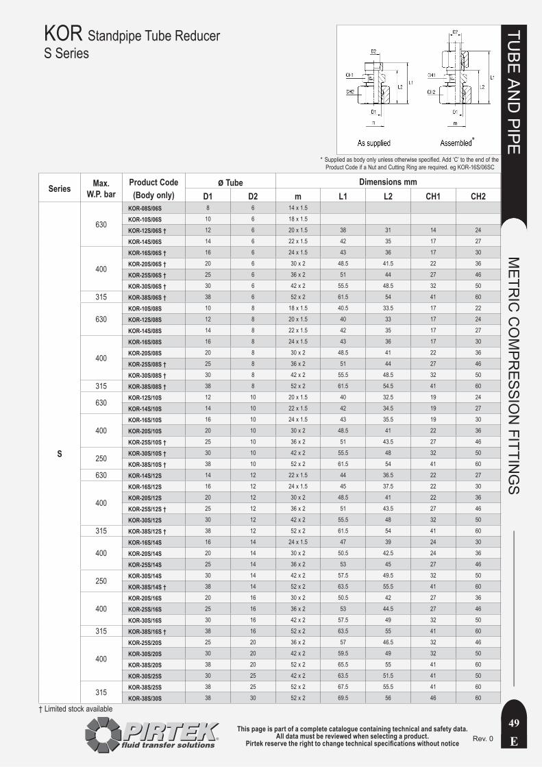
This page is part of a complete catalogue containing technical and safety data.All data must be reviewed when selecting a product.
Pirtek reserve the right to change technical specifications without notice E
TUBE
AN
D PIPE
METR
IC C
OM
PRESSIO
N FITTIN
GS
49Rev. 0
KOR Standpipe Tube ReducerS Series
Series Max. W.P. bar
Product Code(Body only)
ø Tube Dimensions mmD1 D2 m L1 L2 CH1 CH2
S
630
KOR-08S/06S 8 6 14 x 1.5
KOR-10S/06S 10 6 18 x 1.5
KOR-12S/06S † 12 6 20 x 1.5 38 31 14 24
KOR-14S/06S 14 6 22 x 1.5 42 35 17 27
400
KOR-16S/06S † 16 6 24 x 1.5 43 36 17 30
KOR-20S/06S † 20 6 30 x 2 48.5 41.5 22 36
KOR-25S/06S † 25 6 36 x 2 51 44 27 46
KOR-30S/06S † 30 6 42 x 2 55.5 48.5 32 50
315 KOR-38S/06S † 38 6 52 x 2 61.5 54 41 60
630KOR-10S/08S 10 8 18 x 1.5 40.5 33.5 17 22
KOR-12S/08S 12 8 20 x 1.5 40 33 17 24
KOR-14S/08S 14 8 22 x 1.5 42 35 17 27
400
KOR-16S/08S 16 8 24 x 1.5 43 36 17 30
KOR-20S/08S 20 8 30 x 2 48.5 41 22 36
KOR-25S/08S † 25 8 36 x 2 51 44 27 46
KOR-30S/08S † 30 8 42 x 2 55.5 48.5 32 50
315 KOR-38S/08S † 38 8 52 x 2 61.5 54.5 41 60
630 KOR-12S/10S 12 10 20 x 1.5 40 32.5 19 24
KOR-14S/10S 14 10 22 x 1.5 42 34.5 19 27
400KOR-16S/10S 16 10 24 x 1.5 43 35.5 19 30
KOR-20S/10S 20 10 30 x 2 48.5 41 22 36
KOR-25S/10S † 25 10 36 x 2 51 43.5 27 46
250 KOR-30S/10S † 30 10 42 x 2 55.5 48 32 50
KOR-38S/10S † 38 10 52 x 2 61.5 54 41 60
630 KOR-14S/12S 14 12 22 x 1.5 44 36.5 22 27
400
KOR-16S/12S 16 12 24 x 1.5 45 37.5 22 30
KOR-20S/12S 20 12 30 x 2 48.5 41 22 36
KOR-25S/12S † 25 12 36 x 2 51 43.5 27 46
KOR-30S/12S 30 12 42 x 2 55.5 48 32 50
315 KOR-38S/12S † 38 12 52 x 2 61.5 54 41 60
400KOR-16S/14S 16 14 24 x 1.5 47 39 24 30
KOR-20S/14S 20 14 30 x 2 50.5 42.5 24 36
KOR-25S/14S 25 14 36 x 2 53 45 27 46
250 KOR-30S/14S 30 14 42 x 2 57.5 49.5 32 50
KOR-38S/14S † 38 14 52 x 2 63.5 55.5 41 60
400KOR-20S/16S 20 16 30 x 2 50.5 42 27 36
KOR-25S/16S 25 16 36 x 2 53 44.5 27 46
KOR-30S/16S 30 16 42 x 2 57.5 49 32 50
315 KOR-38S/16S † 38 16 52 x 2 63.5 55 41 60
400
KOR-25S/20S 25 20 36 x 2 57 46.5 32 46
KOR-30S/20S 30 20 42 x 2 59.5 49 32 50
KOR-38S/20S 38 20 52 x 2 65.5 55 41 60
KOR-30S/25S 30 25 42 x 2 63.5 51.5 41 50
315 KOR-38S/25S 38 25 52 x 2 67.5 55.5 41 60
KOR-38S/30S 38 30 52 x 2 69.5 56 46 60
† Limited stock available
Supplied as body only unless otherwise specified. Add ‘C’ to the end of the *Product Code if a Nut and Cutting Ring are required. eg KOR-16S/06SC
*
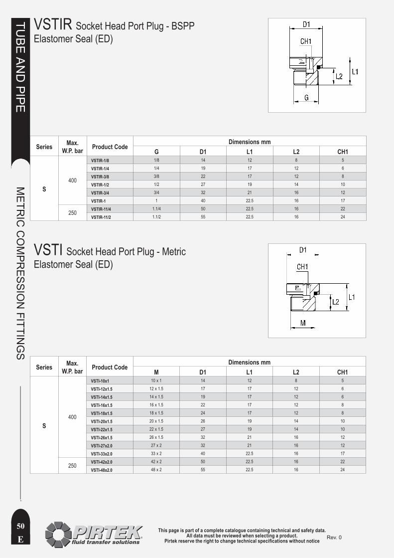
This page is part of a complete catalogue containing technical and safety data.All data must be reviewed when selecting a product.
Pirtek reserve the right to change technical specifications without noticeE
TUBE
AN
D PIPE
METR
IC C
OM
PRESSIO
N FITTIN
GS
50Rev. 0
VSTIR Socket Head Port Plug - BSPPElastomer Seal (ED)
Series Max. W.P. bar Product Code
Dimensions mmG D1 L1 L2 CH1
S400
VSTIR-1/8 1/8 14 12 8 5
VSTIR-1/4 1/4 19 17 12 6
VSTIR-3/8 3/8 22 17 12 8
VSTIR-1/2 1/2 27 19 14 10
VSTIR-3/4 3/4 32 21 16 12
VSTIR-1 1 40 22.5 16 17
250 VSTIR-11/4 1.1/4 50 22.5 16 22
VSTIR-11/2 1.1/2 55 22.5 16 24
VSTI Socket Head Port Plug - MetricElastomer Seal (ED)
Series Max. W.P. bar Product Code
Dimensions mmM D1 L1 L2 CH1
S400
VSTI-10x1 10 x 1 14 12 8 5
VSTI-12x1.5 12 x 1.5 17 17 12 6
VSTI-14x1.5 14 x 1.5 19 17 12 6
VSTI-16x1.5 16 x 1.5 22 17 12 8
VSTI-18x1.5 18 x 1.5 24 17 12 8
VSTI-20x1.5 20 x 1.5 26 19 14 10
VSTI-22x1.5 22 x 1.5 27 19 14 10
VSTI-26x1.5 26 x 1.5 32 21 16 12
VSTI-27x2.0 27 x 2 32 21 16 12
VSTI-33x2.0 33 x 2 40 22.5 16 17
250 VSTI-42x2.0 42 x 2 50 22.5 16 22
VSTI-48x2.0 48 x 2 55 22.5 16 24

This page is part of a complete catalogue containing technical and safety data.All data must be reviewed when selecting a product.
Pirtek reserve the right to change technical specifications without notice E
TUBE
AN
D PIPE
METR
IC C
OM
PRESSIO
N FITTIN
GS
51Rev. 0
BUZ Blanking Cap(Tightening nut not included)
Series bar Product CodeDimensions mm
ø Tube D1 L1
L
315
BUZ-06L/S 6 6 17
BUZ-08L/S 8 8 17
BUZ-10L/S 10 10 20
BUZ-12L/S 12 12 21
BUZ-15L 15 15 21
BUZ-18L 18 18 23
160
BUZ-22L 22 22 23
BUZ-28L 28 28 25
BUZ-35L 35 35 29
BUZ-42L 42 42 30
S
630
BUZ-06L/S 6 6 17
BUZ-08L/S 8 8 17
BUZ-10L/S 10 10 20
BUZ-12L/S 12 12 21
BUZ-14S 14 14 23
400
BUZ-16S 16 16 24
BUZ-20S 20 20 28
BUZ-25S 25 25 31
BUZ-30S 30 30 34
315 BUZ-38S 38 38 38

This page is part of a complete catalogue containing technical and safety data.All data must be reviewed when selecting a product.
Pirtek reserve the right to change technical specifications without noticeE
TUBE
AN
D PIPE
METR
IC C
OM
PRESSIO
N FITTIN
GS
52Rev. 0
Series Max. W.P. bar
Product Code(Plug only)
Dimensions mmø Tube L1 L2 L3 CH1 CH2
L
315
ROV-06L 6 14 7 21.5 12 14
ROV-08L 8 15 8 23 14 17
ROV-10L 10 16 9 24 17 19
ROV-12L 12 17 10 24.5 19 22
ROV-15L 15 18 11 26 24 27
ROV-18L 18 19 11.5 28 27 32
160
ROV-22L 22 21 13.5 30 32 36
ROV-28L 28 22 14.5 31 41 41
ROV-35L 35 25 14.5 36 46 50
ROV-42L 42 27 16 39 55 60
S
630
ROV-06S 6 18 11 26 14 17
ROV-08S 8 20 13 28 17 19
ROV-10S 10 20 12.5 28.5 19 22
ROV-12S 12 22 14.5 30.5 22 24
ROV-14S 14 24 16 34 24 27
400
ROV-16S 16 24 15.5 34 27 30
ROV-20S 20 28 17.5 39 32 36
ROV-25S 25 32 20 44 41 46
ROV-30S 30 34 20.5 47 46 50
315 ROV-38S 38 39 23 54 55 60
ROV Blanking Plug for Tube Ends (Standpipe End Plug)
† Limited stock available
Supplied as body only unless otherwise specified. Add ‘C’ to the end of the Product Code if a Nut *and Cutting Ring are required. eg ROV-12LC
*

This page is part of a complete catalogue containing technical and safety data.All data must be reviewed when selecting a product.
Pirtek reserve the right to change technical specifications without notice E
TUBE
AN
D PIPE
METR
IC C
OM
PRESSIO
N FITTIN
GS
53Rev. 0
Series Max. W.P. bar
Product Code (Body only)
Dimensions mmø Tube G L1 L2 L3 L4 CH1 CH2
L
315
GAI-06LR1/8 6 1/8 16 9 10 23.5 14 14
GAI-08LR1/4 8 1/4 17 10 14 25 19 17
GAI-10LR1/4 10 1/4 18 11 14 26 19 19
GAI-12LR3/8 12 3/8 19 12 14 26.5 24 22
GAI-15LR1/2 15 1/4 21 14 17 29 27 27
GAI-18LR1/2 18 1/2 21 13.5 17 30 27 32
160
GAI-22LR3/4 22 3/4 24 16.5 19 33 36 36
GAI-28LR1 28 1 23.5 16 21.5 32.5 41 41
GAI-35LR11/4 35 1.1/4 28.5 18 23.5 39.5 55 50
GAI-42LR11/2 42 1.1/2 28.5 17.5 25.5 40.5 60 60
S
630
GAI-06SR1/4 6 1/4 19 12 14 27 19 17
GAI-08SR1/4 8 1/4 19 12 14 27 19 19
GAI-10SR3/8 10 3/8 20 12.5 14 28.5 24 22
GAI-12SR3/8 12 3/8 20 12.5 14 28.5 24 24
GAI-14SR1/2 14 1/2 23 15 17 33 30 27
400
GAI-16SR1/2 16 1/2 23 14.5 17 33 30 30
GAI-20SR3/4 20 3/4 26 15.5 19 37 36 36
GAI-25SR1 25 1 27.5 15.5 21.5 39.5 41 46
GAI-30SR11/4 30 1.1/4 32.5 19 23.5 45.5 55 50
315 GAI-38SR11/2 38 1.1/2 34.5 18.5 25.53 49.5 60 60
† Limited stock available
GAI Female Stud CouplingBSPP Thread
Supplied as body only unless otherwise specified. Add ‘C’ to the end of the Product Code if a Nut *and Cutting Ring are required. eg GAI-15LR1/2C
*

This page is part of a complete catalogue containing technical and safety data.All data must be reviewed when selecting a product.
Pirtek reserve the right to change technical specifications without noticeE
TUBE
AN
D PIPE
METR
IC C
OM
PRESSIO
N FITTIN
GS
54Rev. 0
MAV Gauge Coupling Male Metric
MAVE Gauge Coupling Female Metric
Series Max. W.P. bar
Product Code(Body only)
Dimensions mmø Tube G L1 L2 L3 L4 L5 CH1 CH2
L 315
MAV-06LR1/4 6 1/4 4.5 14.5 7.5 14.5 22.5 19 14
MAV-08LR1/4† 8 1/4 4.5 14.5 7.5 14.5 22.5 19 17
MAV-10LR1/4 10 1/4 4.5 14.5 8.5 15.5 23.5 19 19
MAV-12LR1/4 12 1/4 4.5 14.5 8.5 15.5 23.5 19 0.22
S 630
MAV-06SR1/2 6 1/2 5 20 11 18 26 30 17
MAV-08SR1/2 8 1/2 5 20 11 18 26 30 19
MAV-10SR1/2 † 10 1/2 5 20 10.5 18 26.5 30 22
MAV-12SR1/2 12 1/2 5 20 10.5 18 26.5 30 24 † Limited stock available
Series Max. W.P. bar Product Code
Dimensions mmø Tube G m L1 L2 L3 CH1 CH2
L 315
MAVE-06LR1/4 † 6 1/4 12 x 1.5 4.5 14.5 23.5 19 14
MAVE-08LR1/4 † 8 1/4 14 x 1.5 4.5 14.5 25 19 17
MAVE-10LR1/4 † 10 1/4 16 x 1.5 4.5 14.5 25 19 19
MAVE-12LR1/4 † 12 1/4 18 x 1.5 4.5 14.5 26.5 19 22
S 630
MAVE-06SR1/2 † 6 1/2 14 x 1.5 5 20 25 30 17
MAVE-08SR1/2 † 8 1/2 16 x 1.5 5 20 25.5 30 19
MAVE-10SR1/2 † 10 1/2 18 x 1.5 5 20 27.5 30 22
MAVE-12SR1/2 † 12 1/2 20 x 1.5 5 20 27.5 30 24 † Limited stock available
Supplied as body only unless otherwise specified. Add ‘C’ to the end of the Product Code if a Nut *and Cutting Ring are required. eg MAV-12LR1/4C
*

This page is part of a complete catalogue containing technical and safety data.All data must be reviewed when selecting a product.
Pirtek reserve the right to change technical specifications without notice E
TUBE
AN
D PIPE
METR
IC C
OM
PRESSIO
N FITTIN
GS
55Rev. 0
NRV Non Return ValveMale Metric Coupling
Series bar Product Code(Body only)
Dimensions mmø Tube L1 L2 L3 CH1 CH2 ø passage
L
250
NRV-06L 6 68 54 83 19 14 4
NRV-08L † 8 68 54 83 19 17 4
NRV-10L † 10 70 56 85 19 19 4
NRV-12L † 12 76 62 91 32 22 8
NRV-15L 15 81 67 97 41 27 11
160 NRV-18L 18 81 66 98 41 32 11
NRV-22L † 22 94 79 111 50 36 18
100NRV-28L † 28 94 79 112 50 41 18
NRV-35L † 35 116 95 138 70 50 29
NRV-42L † 42 116 94 139 70 60 29
S
400
NRV-06S † 6 72 58 87 19 17 4
NRV-08S † 8 72 58 87 19 19 4
NRV-10S † 10 78 63 95 32 22 7
NRV-12S 12 78 63 95 32 24 8
NRV-14S † 14 85 69 104 41 27 10
NRV-16S 16 85 68 104 41 30 11
NRV-20S 20 98 77 120 50 36 16
250NRV-25S † 25 102 78 126 50 46 18
NRV-30S † 30 124 97 150 70 50 25
NRV-38S † 38 128 96 157 70 60 29
† Limited stock available
Supplied as body only unless otherwise specified. Add ‘C’ to the end of the Product Code if Nuts *and Cutting Rings are required. eg NRV-18LC
*
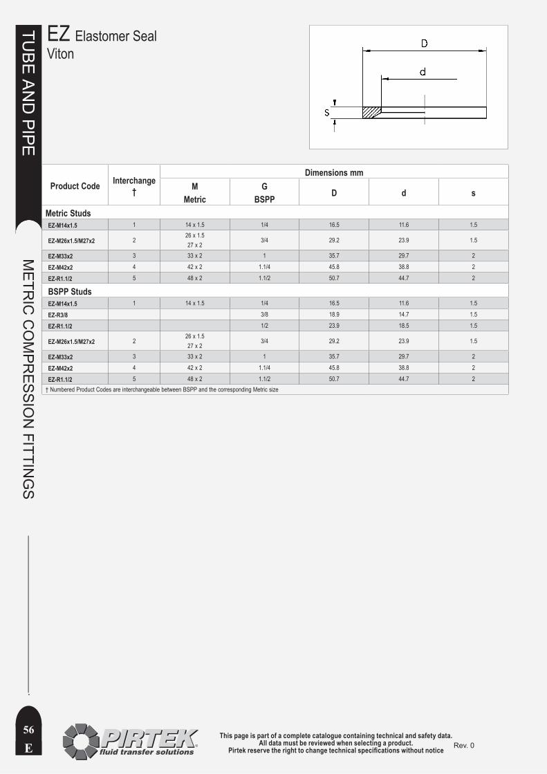
This page is part of a complete catalogue containing technical and safety data.All data must be reviewed when selecting a product.
Pirtek reserve the right to change technical specifications without noticeE
TUBE
AN
D PIPE
METR
IC C
OM
PRESSIO
N FITTIN
GS
56Rev. 0
Product Code Interchange †
Dimensions mmM
MetricG
BSPP D d s
Metric StudsEZ-M14x1.5 1 14 x 1.5 1/4 16.5 11.6 1.5
EZ-M26x1.5/M27x2 226 x 1.527 x 2
3/4 29.2 23.9 1.5
EZ-M33x2 3 33 x 2 1 35.7 29.7 2
EZ-M42x2 4 42 x 2 1.1/4 45.8 38.8 2
EZ-R1.1/2 5 48 x 2 1.1/2 50.7 44.7 2
BSPP StudsEZ-M14x1.5 1 14 x 1.5 1/4 16.5 11.6 1.5
EZ-R3/8 3/8 18.9 14.7 1.5
EZ-R1.1/2 1/2 23.9 18.5 1.5
EZ-M26x1.5/M27x2 226 x 1.527 x 2
3/4 29.2 23.9 1.5
EZ-M33x2 3 33 x 2 1 35.7 29.7 2
EZ-M42x2 4 42 x 2 1.1/4 45.8 38.8 2
EZ-R1.1/2 5 48 x 2 1.1/2 50.7 44.7 2† Numbered Product Codes are interchangeable between BSPP and the corresponding Metric size
EZ Elastomer SealViton
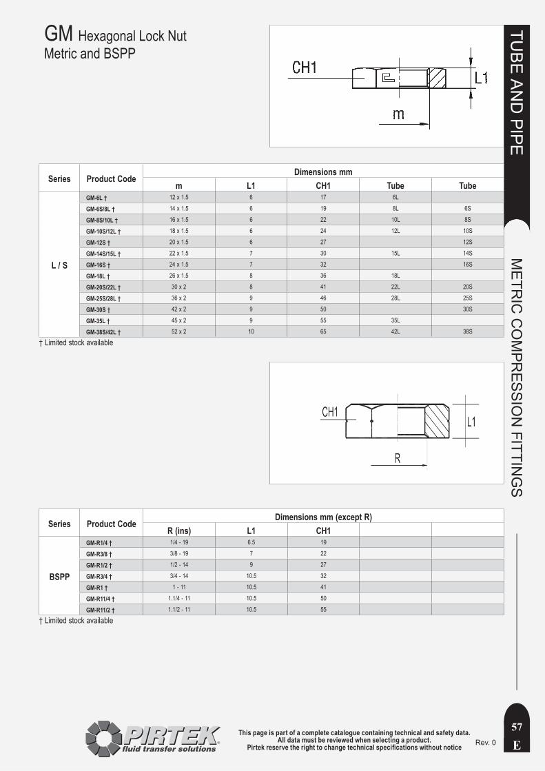
This page is part of a complete catalogue containing technical and safety data.All data must be reviewed when selecting a product.
Pirtek reserve the right to change technical specifications without notice E
TUBE
AN
D PIPE
METR
IC C
OM
PRESSIO
N FITTIN
GS
57Rev. 0
GM Hexagonal Lock NutMetric and BSPP
Series Product CodeDimensions mm
m L1 CH1 Tube Tube
L / S
GM-6L † 12 x 1.5 6 17 6L
GM-6S/8L † 14 x 1.5 6 19 8L 6S
GM-8S/10L † 16 x 1.5 6 22 10L 8S
GM-10S/12L † 18 x 1.5 6 24 12L 10S
GM-12S † 20 x 1.5 6 27 12S
GM-14S/15L † 22 x 1.5 7 30 15L 14S
GM-16S † 24 x 1.5 7 32 16S
GM-18L † 26 x 1.5 8 36 18L
GM-20S/22L † 30 x 2 8 41 22L 20S
GM-25S/28L † 36 x 2 9 46 28L 25S
GM-30S † 42 x 2 9 50 30S
GM-35L † 45 x 2 9 55 35L
GM-38S/42L † 52 x 2 10 65 42L 38S
† Limited stock available
Series Product CodeDimensions mm (except R)
R (ins) L1 CH1
BSPP
GM-R1/4 † 1/4 - 19 6.5 19
GM-R3/8 † 3/8 - 19 7 22
GM-R1/2 † 1/2 - 14 9 27
GM-R3/4 † 3/4 - 14 10.5 32
GM-R1 † 1 - 11 10.5 41
GM-R11/4 † 1.1/4 - 11 10.5 50
GM-R11/2 † 1.1/2 - 11 10.5 55
† Limited stock available

This page is part of a complete catalogue containing technical and safety data.All data must be reviewed when selecting a product.
Pirtek reserve the right to change technical specifications without noticeE
TUBE
AN
D PIPE
METR
IC C
OM
PRESSIO
N FITTIN
GS
58Rev. 0
WE Male Stud Elbow Coupling - NPT
Series Max. W.P. bar
Product Code(Body only)
Dimensions mmø Tube P L1 L2 L3 L4 L5 CH1 CH2
LL 100WE-04LL1/8NPT † 4 1/8 15 11 17 8 21 9 10
WE-06LL1/8NPT † 6 1/8 15 9.5 17 8 21 9 12
WE-08LL1/8NPT † 8 1/8 17 11.5 20 8 23 12 14
L
315
WE-06L1/8NPT 6 1/8 19 12 20 10 27 12 14
WE-08L1/4NPT 8 1/4 21 14 26 15 29 12 17
WE-10L1/4NPT 10 1/4 22 15 27 15 30 14 19
WE-12L3/8NPT 12 3/8 24 17 28 15 32 17 22
WE-15L1/2NPT † 15 1/2 28 21 34 19.5 36 19 27
WE-18L1/2NPT † 18 1/2 31 23.5 36 19.5 40 24 32
160
WE-22L3/4NPT 22 3/4 35 27.5 42 20 44 27 36
WE-28L1NPT † 28 1 38 30.5 48 25 47 36 41
WE-35L11/4NPT † 35 1.1/4 45 34.5 57 25.5 56 41 50
WE-42L11/2NPT † 42 1.1/2 51 40 61 26 63 50 60
S
630
WE-06S1/4NPT † 6 1/4 23 16 26 15 31 12 17
WE-08S1/4NPT † 8 1/4 24 17 27 15 32 14 19
WE-10S3/8NPT † 10 3/8 25 17.5 28 15 34 17 22
WE-12S3/8NPT † 12 3/8 29 21.5 28 15 38 17 24
WE-14S1/2NPT † 14 1/2 30 22 34 19.5 40 19 27
400
WE-16S1/2NPT † 16 1/2 33 24.5 36 19.5 43 24 30
WE-20S3/4NPT † 20 3/4 37 26.5 42 20 48 27 36
WE-25S1NPT † 25 1 42 30 48 25 54 36 46
WE-30S11/4NPT † 30 1.1/4 49 35.5 57 25.5 62 41 50
315 WE-38S11/2NPT † 38 1.1/2 57 41 61 26 72 50 60
† Limited stock available
Supplied as body only unless otherwise specified. Add ‘C’ to the end of the *Product Code if a Nut and Cutting Ring are required. eg WE-12L3/8NPTC
*

This page is part of a complete catalogue containing technical and safety data.All data must be reviewed when selecting a product.
Pirtek reserve the right to change technical specifications without notice E
TUBE
AN
D PIPE
METR
IC C
OM
PRESSIO
N FITTIN
GS
59Rev. 0
WE Male Stud Elbow Coupling - BSPT
Series Max. W.P. bar
Product Code(Body only)
Dimensions mmø Tube P L1 L2 L3 L4 L5 CH1 CH2
LL 100WE-04LLRK1/8 † 4 1/8 15 11 17 8 21 9 10
WE-06LLRK1/8 6 1/8 15 9.5 17 8 21 9 12
WE-08LLRK1/8 † 8 1/8 17 11.5 20 8 23 12 14
L315
WE-06LRK1/8 6 1/8 19 12 20 8 27 12 14
WE-08LRK1/4 8 1/4 21 14 26 12 29 12 17
WE-10LRK1/4 10 1/4 22 15 27 12 30 14 19
WE-10LRK3/8 10 3/8 24 17 28 12 32 17 19
WE-12LRK3/8 12 3/8 24 17 28 12 32 17 22
WE-12LRK1/2 12 1/2 27 20 34 14 34 19 22
WE-15LRK1/2 15 1/2 28 21 34 14 36 19 27
WE-18LRK1/2 18 1/2 31 23.5 36 14 40 24 32
160 WE-28LRK1 28 1 38 30.5 48 18 47 36 41
S630
WE-06SRK1/4 6 1/4 23 16 26 12 31 12 17
WE-08SRK1/4 8 1/4 24 17 27 12 32 14 19
WE-10SRK3/8 10 3/8 25 17.5 28 12 34 17 22
WE-12SRK3/8 12 3/8 29 21.5 28 12 38 17 24
WE-14SRK1/2 14 1/2 30 22 32 14 40 19 27
400 WE-16SRK1/2 16 1/2 33 24.5 32 14 43 24 30
WE-20SRK3/4 20 3/4 37 26.5 42 16 48 27 36
† Limited stock available
Supplied as body only unless otherwise specified. Add ‘C’ to the end of the *Product Code if a Nut and Cutting Ring are required. eg WE-10LRK1/4C
*

This page is part of a complete catalogue containing technical and safety data.All data must be reviewed when selecting a product.
Pirtek reserve the right to change technical specifications without noticeE
TUBE
AN
D PIPE
METR
IC C
OM
PRESSIO
N FITTIN
GS
60Rev. 0
W Equal Elbow Tube Coupling
Series Max. W.P. bar
Product Code(Body only)
Dimensions mmø Tube L1 L2 L3 CH1 CH2
LL 100W-04LL † 4 15 11 21 9 10
W-06LL † 6 15 9.5 21 9 12
W-08LL † 8 17 11.5 23 12 14
L315
W-06L 6 19 12 27 12 14
W-08L 8 21 14 29 12 17
W-10L 10 22 15 30 14 19
W-12L 12 24 17 32 17 22
W-15L 15 28 21 36 19 27
W-18L 18 31 23.5 40 24 32
W-22L 22 35 27.5 44 27 36
W-28L 28 38 30.5 47 36 41
160 W-35L 35 45 34.5 56 41 50
W-42L 42 51 40 63 50 60
S
630
W-06S 6 23 16 31 12 17
W-08S 8 24 17 32 14 19
W-10S 10 25 17.5 34 17 22
W-12S 12 29 21.5 38 17 24
400
W-14S 14 30 22 40 19 27
W-16S 16 33 24.5 43 24 30
W-20S 20 37 26.5 48 27 36
W-25S 25 42 30 54 36 46
W-30S 30 49 35.5 62 41 50
W-38S 38 57 41 72 50 60
† Limited stock available
Supplied as body only unless otherwise specified. Add ‘C’ to the *end of the Product Code if Nuts and Cutting Rings are required. eg W-12LC
*
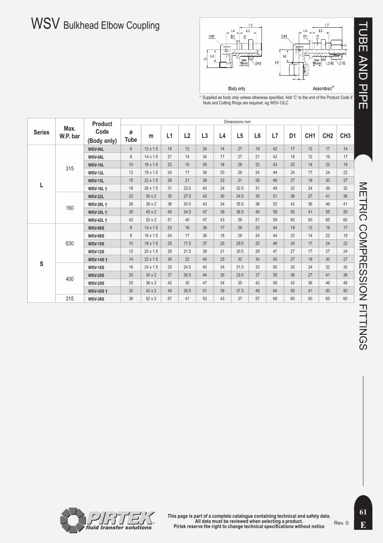
This page is part of a complete catalogue containing technical and safety data.All data must be reviewed when selecting a product.
Pirtek reserve the right to change technical specifications without notice E
TUBE
AN
D PIPE
METR
IC C
OM
PRESSIO
N FITTIN
GS
61Rev. 0
WSV Bulkhead Elbow Coupling
Series Max. W.P. bar
Product Code
(Body only)
Dimensions mm
ø Tube m L1 L2 L3 L4 L5 L6 L7 D1 CH1 CH2 CH3
L
315
WSV-06L 6 12 x 1.5 19 12 34 14 27 19 42 17 12 17 14
WSV-08L 8 14 x 1.5 21 14 34 17 27 21 42 19 12 19 17
WSV-10L 10 16 x 1.5 22 15 35 18 28 22 43 22 14 22 19
WSV-12L 12 18 x 1.5 24 17 36 20 29 24 44 24 17 24 22
WSV-15L 15 22 x 1.5 28 21 38 23 31 28 46 27 19 30 27
WSV-18L † 18 26 x 1.5 31 23.5 40 24 32.5 31 49 32 24 36 32
160
WSV-22L 22 30 x 2 35 27.5 42 30 34.5 35 51 36 27 41 36
WSV-28L † 28 36 x 2 38 30.5 43 34 35.5 38 52 42 36 46 41
WSV-35L † 35 45 x 2 45 34.5 47 39 36.5 45 58 50 41 55 50
WSV-42L † 42 52 x 2 51 40 47 43 36 51 59 60 50 65 60
S
630
WSV-06S 6 14 x 1.5 23 16 36 17 29 23 44 19 12 19 17
WSV-08S 8 16 x 1.5 24 17 36 18 29 24 44 22 14 22 19
WSV-10S 10 18 x 1.5 25 17.5 37 20 29.5 25 46 24 17 24 22
WSV-12S 12 20 x 1.5 29 21.5 38 21 30.5 29 47 27 17 27 24
WSV-14S † 14 22 x 1.5 30 22 40 23 32 30 50 27 19 30 27
400
WSV-16S 16 24 x 1.5 33 24.5 40 24 31.5 33 50 30 24 32 30
WSV-20S 20 30 x 2 37 26.5 44 30 33.5 37 55 36 27 41 36
WSV-25S 25 36 x 2 42 30 47 34 35 42 59 42 36 46 46
WSV-30S † 30 42 x 2 49 35.5 51 39 37.5 49 64 50 41 50 50
315 WSV-38S 38 52 x 2 57 41 53 43 37 57 68 60 50 65 60
Supplied as body only unless otherwise specified. Add ‘C’ to the end of the Product Code if *Nuts and Cutting Rings are required. eg WSV-12LC
*
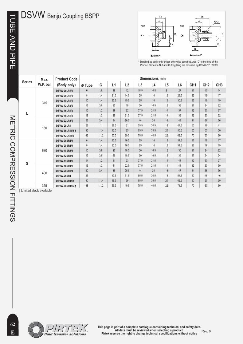
This page is part of a complete catalogue containing technical and safety data.All data must be reviewed when selecting a product.
Pirtek reserve the right to change technical specifications without noticeE
TUBE
AN
D PIPE
METR
IC C
OM
PRESSIO
N FITTIN
GS
62Rev. 0
DSVW Banjo Coupling BSPP
Series Max. W.P. bar
Product Code(Body only)
Dimensions mmø Tube G L1 L2 L3 L4 L5 L6 CH1 CH2 CH3
L
315
DSVW-06LR1/8 6 1/8 19 12 18.5 10.5 8 27 17 17 14
DSVW-08LR1/4 8 1/4 21.5 14.5 25 14 12 29.5 22 19 17
DSVW-10LR1/4 10 1/4 22.5 15.5 25 14 12 30.5 22 19 19
DSVW-12LR3/8 12 3/8 25 18 30 16.5 12 33 27 24 22
DSVW-15LR1/2 15 1/2 29 22 37.5 21.5 14 37 32 30 27
DSVW-18LR1/2 18 1/2 29 21.5 37.5 21.5 14 38 32 30 32
160
DSVW-22LR3/4 22 3/4 34 26.5 44 24 16 43 41 36 36
DSVW-28LR1 28 1 38.5 31 55.5 30.5 18 47.5 50 46 41
DSVW-35LR11/4 † 35 1.1/4 45.5 35 65.5 35.5 20 56.5 60 55 50
DSVW-42LR11/2 42 1.1/2 50.5 39.5 75.5 40.5 22 62.5 70 60 60
S
630
DSVW-06SR1/4 6 1/4 23.5 16.5 25 14 12 31.5 22 19 17
DSVW-08SR1/4 8 1/4 23.5 16.5 25 14 12 31.5 22 19 19
DSVW-10SR3/8 10 3/8 26 18.5 30 16.5 12 35 27 24 22
DSVW-12SR3/8 12 3/8 26 18.5 30 16.5 12 35 27 24 24
DSVW-14SR1/2 14 1/2 31 23 37.5 21.5 14 41 32 30 27
400
DSVW-16SR1/2 16 1/2 31 22.5 37.5 21.5 14 41 32 30 30
DSVW-20SR3/4 20 3/4 36 25.5 44 24 16 47 41 36 36
DSVW-25SR1 25 1 42.5 31.5 55.5 30.5 18 54.5 50 46 46
DSVW-30SR11/4 30 1.1/4 49.5 36 65.5 35.5 20 62.5 60 55 50
315 DSVW-38SR11/2 † 38 1.1/2 56.5 40.5 75.5 40.5 22 71.5 70 60 60
† Limited stock available
Supplied as body only unless otherwise specified. Add ‘C’ to the end of the *Product Code if a Nut and Cutting Ring are required. eg DSVW-12LR3/8C
*
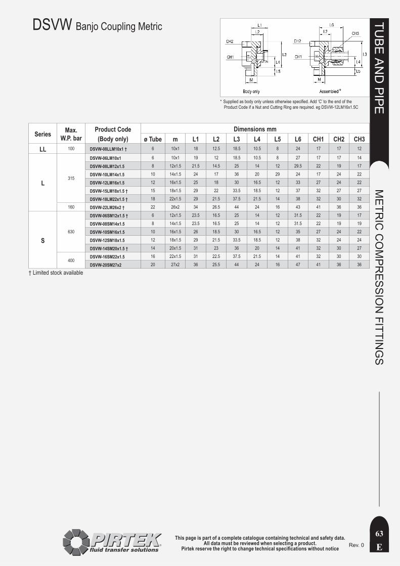
This page is part of a complete catalogue containing technical and safety data.All data must be reviewed when selecting a product.
Pirtek reserve the right to change technical specifications without notice E
TUBE
AN
D PIPE
METR
IC C
OM
PRESSIO
N FITTIN
GS
63Rev. 0
DSVW Banjo Coupling Metric
Series Max. W.P. bar
Product Code(Body only)
Dimensions mmø Tube m L1 L2 L3 L4 L5 L6 CH1 CH2 CH3
LL 100 DSVW-08LLM10x1 † 6 10x1 18 12.5 18.5 10.5 8 24 17 17 12
L315
DSVW-06LM10x1 6 10x1 19 12 18.5 10.5 8 27 17 17 14
DSVW-08LM12x1.5 8 12x1.5 21.5 14.5 25 14 12 29.5 22 19 17
DSVW-10LM14x1.5 10 14x1.5 24 17 36 20 29 24 17 24 22
DSVW-12LM16x1.5 12 16x1.5 25 18 30 16.5 12 33 27 24 22
DSVW-15LM18x1.5 † 15 18x1.5 29 22 33.5 18.5 12 37 32 27 27
DSVW-18LM22x1.5 † 18 22x1.5 29 21.5 37.5 21.5 14 38 32 30 32
160 DSVW-22LM26x2 † 22 26x2 34 26.5 44 24 16 43 41 36 36
S630
DSVW-06SM12x1.5 † 6 12x1.5 23.5 16.5 25 14 12 31.5 22 19 17
DSVW-08SM14x1.5 8 14x1.5 23.5 16.5 25 14 12 31.5 22 19 19
DSVW-10SM16x1.5 10 16x1.5 26 18.5 30 16.5 12 35 27 24 22
DSVW-12SM18x1.5 12 18x1.5 29 21.5 33.5 18.5 12 38 32 24 24
DSVW-14SM20x1.5 † 14 20x1.5 31 23 36 20 14 41 32 30 27
400DSVW-16SM22x1.5 16 22x1.5 31 22.5 37.5 21.5 14 41 32 30 30
DSVW-20SM27x2 20 27x2 36 25.5 44 24 16 47 41 36 36
† Limited stock available
Supplied as body only unless otherwise specified. Add ‘C’ to the end of the *Product Code if a Nut and Cutting Ring are required. eg DSVW-12LM16x1.5C
*

This page is part of a complete catalogue containing technical and safety data.All data must be reviewed when selecting a product.
Pirtek reserve the right to change technical specifications without noticeE
TUBE
AN
D PIPE
METR
IC C
OM
PRESSIO
N FITTIN
GS
64Rev. 0
EVW Adjustable Elbow Coupling
Series Max. W.P. bar
Product Code(Body only)
Dimensions mmø Tube m L1 L2 L3 L4 CH1 CH2
L
315
EVW-06L 6 12 x 1.5 19 12 26 27 12 14EVW-08L 8 14 x 1.5 21 14 27.5 29 12 17EVW-10L 10 16 x 1.5 22 15 29 30 14 19EVW-12L 12 18 x 1.5 24 17 29.5 32 17 22EVW-15L 15 22 x 1.5 28 21 32.5 36 19 27EVW-18L 18 26 x 1.5 31 23.5 35.5 40 24 32
160
EVW-22L 22 30 x 2 35 27.5 38.5 44 27 36EVW-28L 28 36 x 2 38 30.5 41.5 47 36 41EVW-35L 35 45 x 2 45 34.5 51.5 56 41 50EVW-42L 42 52 x 2 51 40 56 63 50 60
S
630
EVW-06S 6 14 x 1.5 23 16 27 31 12 17EVW-08S 8 16 x 1.5 24 17 27.5 32 14 19EVW-10S 10 18 x 1.5 25 17.5 30 34 17 22EVW-12S 12 20 x 1.5 29 21.5 31 38 17 24EVW-14S 14 22 x 1.5 30 22 35 40 19 27
400
EVW-16S 16 24 x 1.5 33 24.5 36.5 43 24 30EVW-20S 20 30 x 2 37 26.5 44.5 48 27 36EVW-25S 25 36 x 2 42 30 50 54 36 46EVW-30S 30 42 x 2 49 35.5 55.5 62 41 50
315 EVW-38S 38 52 x 2 57 41 63 72 50 60
Supplied as body only unless otherwise specified. Add ‘C’ to the end of the *Product Code if a Nut and Cutting Ring are required. eg EVW-15LC
*
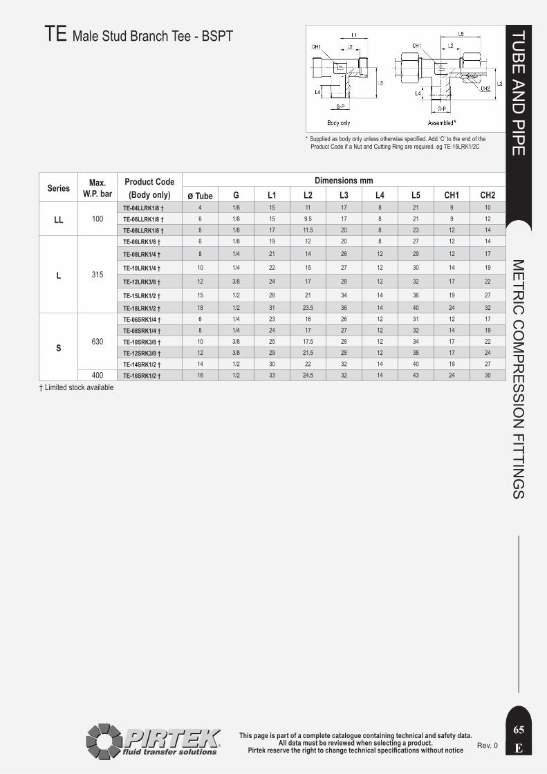
This page is part of a complete catalogue containing technical and safety data.All data must be reviewed when selecting a product.
Pirtek reserve the right to change technical specifications without notice E
TUBE
AN
D PIPE
METR
IC C
OM
PRESSIO
N FITTIN
GS
65Rev. 0
Series Max. W.P. bar
Product Code(Body only)
Dimensions mmø Tube G L1 L2 L3 L4 L5 CH1 CH2
LL 100TE-04LLRK1/8 † 4 1/8 15 11 17 8 21 9 10
TE-06LLRK1/8 † 6 1/8 15 9.5 17 8 21 9 12
TE-08LLRK1/8 † 8 1/8 17 11.5 20 8 23 12 14
L 315
TE-06LRK1/8 † 6 1/8 19 12 20 8 27 12 14
TE-08LRK1/4 † 8 1/4 21 14 26 12 29 12 17
TE-10LRK1/4 † 10 1/4 22 15 27 12 30 14 19
TE-12LRK3/8 † 12 3/8 24 17 28 12 32 17 22
TE-15LRK1/2 † 15 1/2 28 21 34 14 36 19 27
TE-18LRK1/2 † 18 1/2 31 23.5 36 14 40 24 32
S630
TE-06SRK1/4 † 6 1/4 23 16 26 12 31 12 17
TE-08SRK1/4 † 8 1/4 24 17 27 12 32 14 19
TE-10SRK3/8 † 10 3/8 25 17.5 28 12 34 17 22
TE-12SRK3/8 † 12 3/8 29 21.5 28 12 38 17 24
TE-14SRK1/2 † 14 1/2 30 22 32 14 40 19 27
400 TE-16SRK1/2 † 16 1/2 33 24.5 32 14 43 24 30
† Limited stock available
TE Male Stud Branch Tee - BSPT
Supplied as body only unless otherwise specified. Add ‘C’ to the end of the *Product Code if a Nut and Cutting Ring are required. eg TE-15LRK1/2C
*
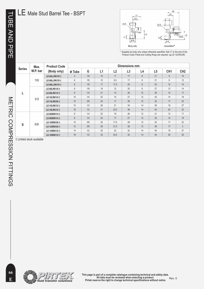
This page is part of a complete catalogue containing technical and safety data.All data must be reviewed when selecting a product.
Pirtek reserve the right to change technical specifications without noticeE
TUBE
AN
D PIPE
METR
IC C
OM
PRESSIO
N FITTIN
GS
66Rev. 0
LE Male Stud Barrel Tee - BSPT
Series Max. W.P. bar
Product Code(Body only)
Dimensions mmø Tube G L1 L2 L3 L4 L5 CH1 CH2
L
100LE-04LLRK1/8 † 4 1/8 15 11 17 8 21 9 10
LE-06LLRK1/8 † 6 1/8 15 9.5 17 8 21 9 12
LE-08LLRK1/8 † 8 1/8 17 11.5 20 8 23 12 14
315
LE-06LRK1/8 † 6 1/8 19 12 20 8 27 12 14
LE-08LRK1/4 † 8 1/4 21 14 26 12 29 12 17
LE-10LRK1/4 † 10 1/4 22 15 27 12 30 14 19
LE-12LRK3/8 † 12 3/8 24 17 28 12 32 17 22
LE-15LRK1/2 † 15 1/2 28 21 34 14 36 19 27
LE-18LRK1/2 † 18 1/2 31 23.5 36 14 40 24 32
S 630
LE-06SRK1/4 † 6 1/4 23 16 26 12 31 12 17
LE-08SRK1/4 † 8 1/4 24 17 27 12 32 14 19
LE-10SRK3/8 † 10 3/8 25 17.5 28 12 34 17 22
LE-12SRK3/8 † 12 3/8 29 21.5 28 12 38 17 2
LE-14SRK1/2 † 14 1/2 30 22 32 14 40 19 27
LE-16SRK1/2 † 16 1/2 33 24.5 32 14 43 24 30
† Limited stock available
Supplied as body only unless otherwise specified. Add ‘C’ to the end of the *Product Code if Nuts and Cutting Rings are required. eg LE-12LRK3/8C
*

This page is part of a complete catalogue containing technical and safety data.All data must be reviewed when selecting a product.
Pirtek reserve the right to change technical specifications without notice E
TUBE
AN
D PIPE
METR
IC C
OM
PRESSIO
N FITTIN
GS
67Rev. 0
Series Max. W.P. bar
Product Code(Body only)
Dimensions mmø Tube m L1 L2 L3 L4 CH1 CH2
L
315
EVT-06L 6 12 x 1.5 19 12 26 27 12 14
EVT-08L 8 14 x 1.5 21 14 27.5 29 12 17
EVT-10L 10 16 x 1.5 22 15 29 30 14 19
EVT-12L 12 18 x 1.5 24 17 29.5 32 17 22
EVT-15L 15 22 x 1.5 28 21 32.5 36 19 27
EVT-18L 18 26 x 1.5 31 23.5 35.5 40 24 32
160
EVT-22L 22 30 x 2 35 27.5 38.5 44 27 36
EVT-28L 28 36 x 2 38 30.5 41.5 47 36 41
EVT-35L 35 45 x 2 45 34.5 51.5 56 41 50
EVT-42L 42 52 x 2 51 40 56 63 50 60
S
630
EVT-06S 6 14 x 1.5 23 16 27 31 12 17
EVT-08S 8 16 x 1.5 24 17 27.5 32 14 19
EVT-10S 10 18 x 1.5 25 17.5 30 34 17 22
EVT-12S 12 20 x 1.5 29 21.5 31 38 17 24
EVT-14S 14 22 x 1.5 30 22 35 40 19 27
400
EVT-16S 16 24 x 1.5 33 24.5 36.5 43 24 30
EVT-20S 20 30 x 2 37 26.5 44.5 48 27 36
EVT-25S 25 36 x 2 42 30 50 54 36 46
EVT-30S 30 42 x 2 49 35.5 55.5 62 41 50
315 EVT-38S 38 52 x 2 57 41 63 72 50 60
EVT Adjustable Branch Tee Coupling
Supplied as body only unless otherwise specified. Add ‘C’ to the end of the *Product Code if Nuts and Cutting Rings are required. eg EVT-12LC
*
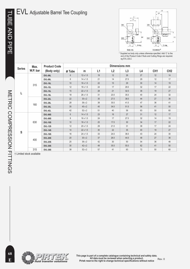
This page is part of a complete catalogue containing technical and safety data.All data must be reviewed when selecting a product.
Pirtek reserve the right to change technical specifications without noticeE
TUBE
AN
D PIPE
METR
IC C
OM
PRESSIO
N FITTIN
GS
68Rev. 0
EVL Adjustable Barrel Tee Coupling
Series Max. W.P. bar
Product Code(Body only)
Dimensions mmø Tube m L1 L2 L3 L4 CH1 CH2
L
315
EVL-06L 6 12 x 1.5 19 12 26 27 12 14
EVL-08L 8 14 x 1.5 21 14 27.5 29 12 17
EVL-10L 10 16 x 1.5 22 15 29 30 14 19
EVL-12L 12 18 x 1.5 24 17 29.5 32 17 22
EVL-15L 15 22 x 1.5 28 21 32.5 36 19 27
EVL-18L 18 26 x 1.5 31 23.5 35.5 40 24 32
160
EVL-22L 22 30 x 2 35 27.5 38.5 44 27 36
EVL-28L 28 36 x 2 38 30.5 41.5 47 36 41
EVL-35L 35 45 x 2 45 34.5 51.5 56 41 50
EVL-42L 42 52 x 2 51 40 56 63 50 60
S
630
EVL-06S 6 14 x 1.5 23 16 27 31 12 17
EVL-08S 8 16 x 1.5 24 17 27.5 32 14 19
EVL-10S 10 18 x 1.5 25 17.5 30 34 17 22
EVL-12S 12 20 x 1.5 29 21.5 31 38 17 24
EVL-14S 14 22 x 1.5 30 22 35 40 19 27
400
EVL-16S 16 24 x 1.5 33 24.5 36.5 43 24 30
EVL-20S 20 30 x 2 37 26.5 44.5 48 27 36
EVL-25S 25 36 x 2 42 30 50 54 36 46
EVL-30S 30 42 x 2 49 35.5 55.5 62 41 50
315 EVL-38S 38 52 x 2 57 41 63 72 50 60
† Limited stock available
Supplied as body only unless otherwise specified. Add ‘C’ to the *end of the Product Code if Nuts and Cutting Rings are required. eg EVL-22LC
*
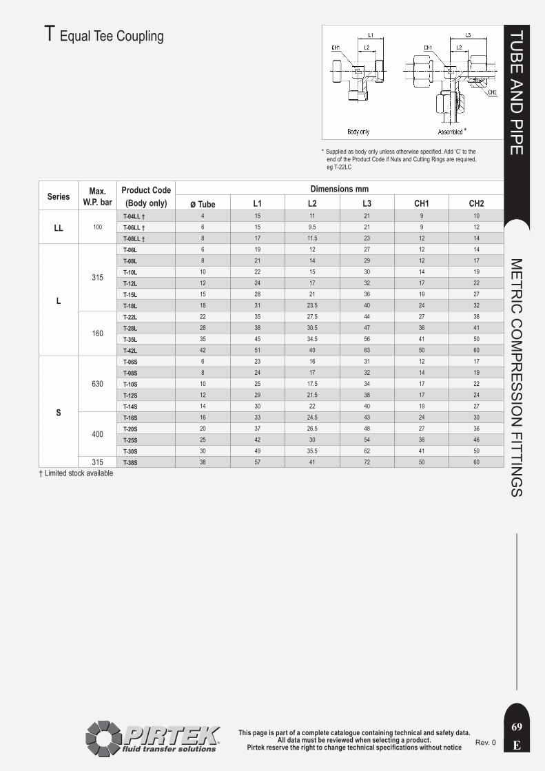
This page is part of a complete catalogue containing technical and safety data.All data must be reviewed when selecting a product.
Pirtek reserve the right to change technical specifications without notice E
TUBE
AN
D PIPE
METR
IC C
OM
PRESSIO
N FITTIN
GS
69Rev. 0
T Equal Tee Coupling
Series Max. W.P. bar
Product Code(Body only)
Dimensions mmø Tube L1 L2 L3 CH1 CH2
LL 100T-04LL † 4 15 11 21 9 10
T-06LL † 6 15 9.5 21 9 12
T-08LL † 8 17 11.5 23 12 14
L
315
T-06L 6 19 12 27 12 14
T-08L 8 21 14 29 12 17
T-10L 10 22 15 30 14 19
T-12L 12 24 17 32 17 22
T-15L 15 28 21 36 19 27
T-18L 18 31 23.5 40 24 32
160
T-22L 22 35 27.5 44 27 36
T-28L 28 38 30.5 47 36 41
T-35L 35 45 34.5 56 41 50
T-42L 42 51 40 63 50 60
S
630
T-06S 6 23 16 31 12 17
T-08S 8 24 17 32 14 19
T-10S 10 25 17.5 34 17 22
T-12S 12 29 21.5 38 17 24
T-14S 14 30 22 40 19 27
400
T-16S 16 33 24.5 43 24 30
T-20S 20 37 26.5 48 27 36
T-25S 25 42 30 54 36 46
T-30S 30 49 35.5 62 41 50
315 T-38S 38 57 41 72 50 60
† Limited stock available
Supplied as body only unless otherwise specified. Add ‘C’ to the *end of the Product Code if Nuts and Cutting Rings are required. eg T-22LC
*
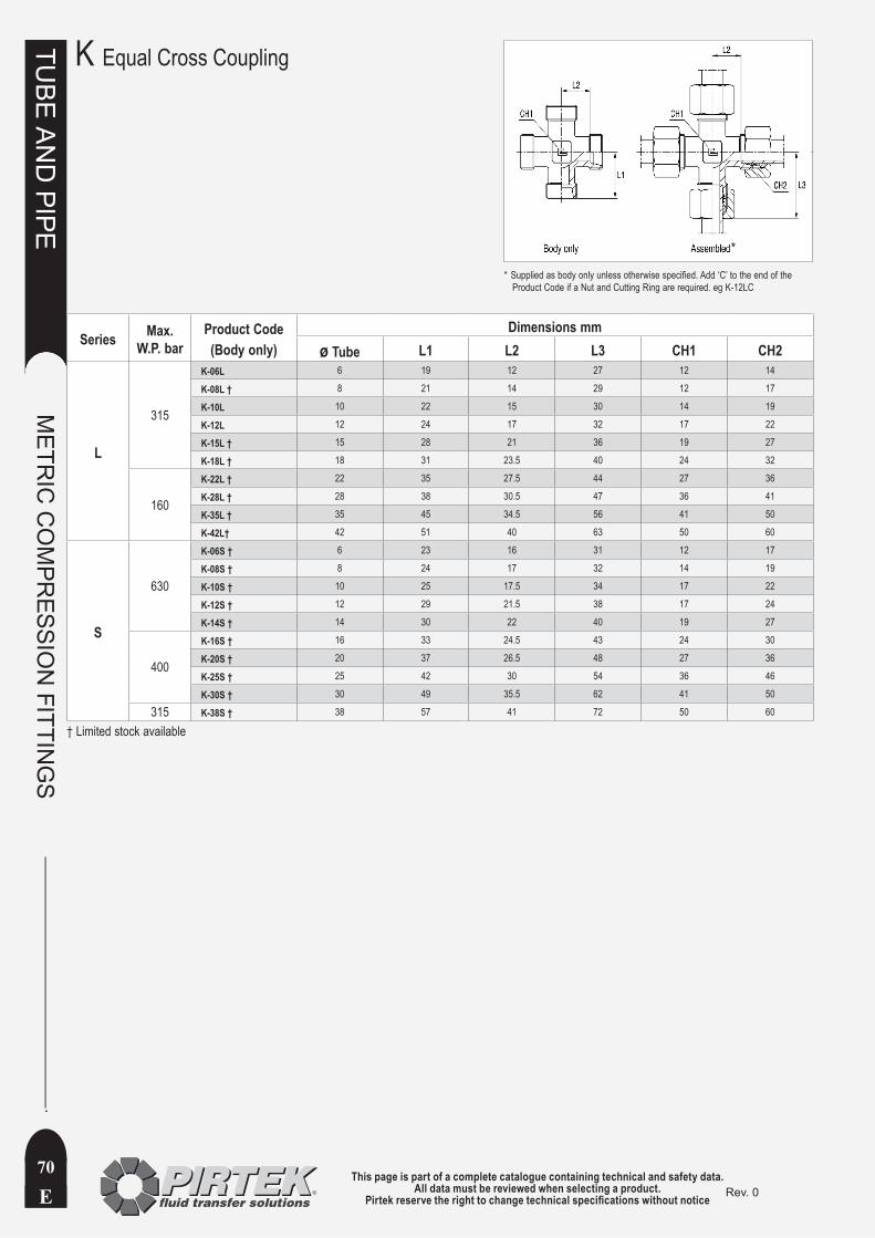
This page is part of a complete catalogue containing technical and safety data.All data must be reviewed when selecting a product.
Pirtek reserve the right to change technical specifications without noticeE
TUBE
AN
D PIPE
METR
IC C
OM
PRESSIO
N FITTIN
GS
70Rev. 0
K Equal Cross Coupling
Series Max. W.P. bar
Product Code(Body only)
Dimensions mmø Tube L1 L2 L3 CH1 CH2
L
315
K-06L 6 19 12 27 12 14
K-08L † 8 21 14 29 12 17
K-10L 10 22 15 30 14 19
K-12L 12 24 17 32 17 22
K-15L † 15 28 21 36 19 27
K-18L † 18 31 23.5 40 24 32
160
K-22L † 22 35 27.5 44 27 36
K-28L † 28 38 30.5 47 36 41
K-35L † 35 45 34.5 56 41 50
K-42L† 42 51 40 63 50 60
S
630
K-06S † 6 23 16 31 12 17
K-08S † 8 24 17 32 14 19
K-10S † 10 25 17.5 34 17 22
K-12S † 12 29 21.5 38 17 24
K-14S † 14 30 22 40 19 27
400
K-16S † 16 33 24.5 43 24 30
K-20S † 20 37 26.5 48 27 36
K-25S † 25 42 30 54 36 46
K-30S † 30 49 35.5 62 41 50
315 K-38S † 38 57 41 72 50 60
† Limited stock available
Supplied as body only unless otherwise specified. Add ‘C’ to the end of the *Product Code if a Nut and Cutting Ring are required. eg K-12LC
*

This page is part of a complete catalogue containing technical and safety data.All data must be reviewed when selecting a product.
Pirtek reserve the right to change technical specifications without notice E
TUBE
AN
D PIPE
METR
IC C
OM
PRESSIO
N FITTIN
GS
71Rev. 0
This page is part of a complete catalogue containing technical and safety data.All data must be reviewed when selecting a product.
Pirtek reserve the right to change technical specifications without noticeE
TUBE
AN
D PIPE
METR
IC C
OM
PRESSIO
N FITTIN
GS
72Rev. 0
Tube and Pipe Compression FittingsPage Page
CDS Tube 4 AS 43
Copper Tube 6 Assembly Instructions 27
Imperial Tube 4 BUZ 51
Introduction to Tube & Pipe 2 Cutting Rings 24
Metric Tube 5 D 31
Sched 40 3 DB4 31
Sched 80 3 DSVW-BSPP 62
Sched 160 3 DSVW-Metric 63
Schedule Pipe Data 3 EDKO 41
EVGE 47
Tube Clamps EVGER 46
EVL 68
CCA 8 EVT 67
CCB 8 EVW 64
CCx Mounting 11 EZ 56
CCx Stacked 10 G 39
CCx Standard 9 GAI 53
CFx Mounting 14 GE 33-38
CFx Stacked 13 GE-BSPP ED 36
CFx Standard 12 GE-BSPP Form B 35
CHx Double 18 GE-BSPT 34
CHx Single 18 GE-Metric ED 38
Clamp Components 19 GE-Metric Form B 37
Clamp Spacings 20 GE-Metric Taper 37
CPx Double 15 GE-NPT 33
CPx Mounting 17 GE-UN-O 38
CPx Single 15 GM 57
CPx Stacked 16 GV 40
Rubber Inserts 9, 15 K 70
Shear Force for Clamps 20 KOR 48-49
Tube Clamps 7 LE-BSPT 66
M 32
MAV 54
MAVE 54
Nomenclature 29
NRV 55
Pictorial Index 23
RI 45
ROV 52
SKA 44
Stud Dimensions 25-26
SV 42
T 69
TE-BSPT 65
Tightening torques 28
VSTI 50
VSTIR 50
W 60
WE-BSPT 59
WE-NPT 58
WSV 61
ALPHANUMERIC INDEX