tube heater troubleshooting guide · pdf filetube heater troubleshooting guide ... picture 1...
TRANSCRIPT

TUBE HEATERTROUBLESHOOTING GUIDE
MODELS: DTH(S) Series Tube Heaterer
Detroit Radiant Products Company21400 Hoover Road • Warren • Michigan • 48089 • (586) 756-0950 • Fax: (586) 756-2626
website: www.reverberray.com email: [email protected]
THESE HEATERS MUST BE INSTALLED AND SERVICED BY TRAINED GASINSTALLATION AND SERVICE PERSONNEL ONLY. READ AND UNDERSTAND ALLINSTRUCTIONS THOROUGHLY BEFORE ATTEMPTING TO INSTALL, OPERATE ORSERVICE THE DETROIT RADIANT PRODUCTS COMPANY HEATER. FAILURE TOCOMPLY WITH THESE WARNINGS AND INSTRUCTIONS, AND THOSE ON THEHEATER, COULD RESULT IN PERSONAL INJURY, DEATH, FIRE, ASPHYXIATION AND/OR PROPERTY DAMAGE. RETAIN THESE INSTRUCTIONS FOR FUTURE REFERENCE.
CAUTION! Heater may be hot. Do not store or use gasoline or other flammablevapors and liquids in the vicinity of this or any other appliance. Note presence offlammable gas and electrical shock hazard.
WARNING! Extinguish open flame while servicing heaters. Test for gas leaks withsoap and water solution only. Wear safety glasses while servicing unit.
Approval Standards and Certifications
Detroit Radiant Products units comply with or are certified by the following Organizationsor Standards:
- American National Standards (ANSI Z83.6)- Occupational Safety and Health Act (OSHA)- American Gas Association (AGA)- International Approval Services (IAS)
FOR YOUR SAFETY!
IF YOU SMELL GAS:1. Open windows.2. Do not touch electrical switches.3. Extinguish any open flame.4. Immediately call your gas supplier.
SHUTDOWN INSTRUCTIONS!
1. Open electrical circuit.
2. Rotate heater’s manual gasvalve knob to “OFF” position.
IMPORTANT: Any alteration of the system or of the factory-authorized components specifiedeither in this manual or by Detroit Radiant Products Company voids all certification and warranties.

Table of ContentsTools Recommended To Troubleshoot Heaters
DTHS-2 Wiring Diagram & Theory of Operation
DTHS-3 Wiring Diagram & Theory of Operation
Burner Photographs -2 & -3 Series Heaters
Component Photographs
Troubleshooting Flow Chart
General Troubleshooting Reference & Solution Chart
Troubleshooting Solutions
Component History Chart
How To... (For Trouble Shooting Procedures)
2
3
4
5
6
7, 8
9, 10
11-19
20
21-23
1
This symbol appears when directions indicate the presence of flammable gas.
This symbol appears when directions indicate the presence an electrical shock hazard.

-Digital Multimeter - Used for troubleshooting & testing electrical circuits.(Part 1A783 from Grainger)
-Flame Rectification Meter - Used for testing rectification of flame with the digital multimeter.(Channel Products)
-Digital Manometer Kit - Used for taking gas pressure, digitally.(Part 100281-21 from Dwyer Instruments)
-Liquid Manometer Kit - Used for taking gas pressure, via a liquid manometer.(Part 115010-00 from Dwyer Instruments)
-Digital Hygro-Thermometer (Amprobe #TH-2) - Reads temperature from -10 to 50OC and relative humidity from5-95%. (Part 1P124 from Grainger)
-Incline Manometer - Used for measuring pressure inside burner box. Provides data for pressureswitch. (Cat# 172 from Dwyer Instruments)
-1/4” Nut Driver - Can be used to remove screws holding top on.(Part 5X509 from Grainger)
-Pliers 8” - Tool for burner box access.(Part 6C183 from Grainger)
-Pipe Wrench 8” - Can be used to disassemble gas train assembly.(Part 4A497 from Grainger)
-Ratcheting Box Wrench - Can be used to remove orifice and bolts. (size 7/16” and 3/8”)(Part 1AMW9 from Grainger)
-6” Steel Rule - Used for measuring air orifice size.(Part 6C289 from Grainger)
-Terminals 1/4” Female - Extra female spade terminals.
-Barb Fitting - Fitting to take gas pressure at the valve.
-Vinyl Tubing - Tubing for pressure measurements. (size 5/16” x 3’)
-Jumpers/Connectors - Used to jump out the pressure switches.
-Self Tapping Screws - Extra screws.
-Drill Bits 1-60, A-Z - Drill Bits 1-60, A-Z, for measuring gas orifice size (DMS).
-Manuals - DX, DX-2 or XTS Series Installation, Operation & Maintenance manuals (IOM’s).
Tools Recommended to Troubleshoot Heaters
2
3
2. Theory of Operation
2.1 DTHS-2 Models: 40,000 BTU/H through 100,000 BTU/H
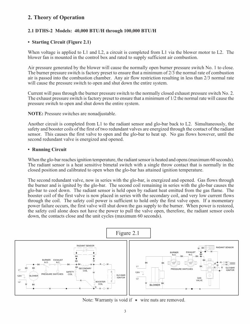
• Starting Circuit (Figure 2.1)
When voltage is applied to L1 and L2, a circuit is completed from L1 via the blower motor to L2. Theblower fan is mounted in the control box and rated to supply sufficient air combustion.
Air pressure generated by the blower will cause the normally open burner pressure switch No. 1 to close.The burner pressure switch is factory preset to ensure that a minimum of 2/3 the normal rate of combustionair is passed into the combustion chamber. Any air flow restriction resulting in less than 2/3 normal ratewill cause the pressure switch to open and shut down the entire system.
Current will pass through the burner pressure switch to the normally closed exhaust pressure switch No. 2.The exhaust pressure switch is factory preset to ensure that a minimum of 1/2 the normal rate will cause thepressure switch to open and shut down the entire system.
NOTE: Pressure switches are nonadjustable.
Another circuit is completed from L1 to the radiant sensor and glo-bar back to L2. Simultaneously, thesafety and booster coils of the first of two redundant valves are energized through the contact of the radiantsensor. This causes the first valve to open and the glo-bar to heat up. No gas flows however, until thesecond redundant valve is energized and opened.
• Running Circuit
When the glo-bar reaches ignition temperature, the radiant sensor is heated and opens (maximum 60 seconds).The radiant sensor is a heat sensitive bimetal switch with a single throw contact that is normally in theclosed position and calibrated to open when the glo-bar has attained ignition temperature.
The second redundant valve, now in series with the glo-bar, is energized and opened. Gas flows throughthe burner and is ignited by the glo-bar. The second coil remaining in series with the glo-bar causes theglo-bar to cool down. The radiant sensor is held open by radiant heat emitted from the gas flame. Thebooster coil of the first valve is now placed in series with the secondary coil, and very low current flowsthrough the coil. The safety coil power is sufficient to hold only the first valve open. If a momentarypower failure occurs, the first valve will shut down the gas supply to the burner. When power is restored,the safety coil alone does not have the power to pull the valve open, therefore, the radiant sensor coolsdown, the contacts close and the unit cycles (maximum 60 seconds).
Note: Warranty is void if wire nuts are removed.
PRESSURE SWITCHESBLOWER
BURNERN.O.
EXHAUSTN.C.
RADIANT SENSOR
SECONDARY COILSAFETY
COIL
BOOSTER COIL
GLO-BAR IGNITOR
BKBK
BK
BK
BK
BK
BK
BK
W W
W
W
W
W
R
R RR
R
W
120V
L2
L1
BK W
BLOWER
PRESSURE SWITCHES
RADIANT SENSOR
GLO-BAR IGNITOR
GAS VALVE
BURNERN.O.
EXHAUSTN.C.
WWW
R
W
W
W
W
BK BK
BK
BK BK
BK
BK
BK
L1
L2
120V
R
R
R
BKW
Figure 2.1

4
Theory of Operation
2.2 DTHS-3 Models: 125,000 BTU/H and 150,000 BTU/H
• Starting Circuit (Figure 2.2)
When voltage is applied to L1 and L2, a circuit is completed from L1 via the blower motor to L2.The blower fan is mounted in the control box and rated to supply sufficient air for combustion.
Air pressure generated by the blower will cause the normally-open burner pressure switch No. 1to close. The control completes another circuit from L1 to the hot surface ignition control andback to L2. There is a five-second delay, then the glo-bar is powered. After the glo-barhas been powered for 45 seconds, the control causes the gas valve to open and initiatesthe ignition trial. Power to the glo-bar is shut off during the last two or three seconds of theignition trial.
• Starting Circuit
When power is removed from the glo-bar, the glo-bar is utilized as a flame probe. As long as aflame is present, the valve is held open. If the flame is lost, the control acts to close the valvewithin one second, and a new trial sequence identical to that at start-up is initiated. If proof offlame is not established within 8 seconds, the unit will lock out. If lockout occurs, the control canbe reset by briefly interrupting the power source.
PRESSURE SWITCHESBLOWER
BURNERN.O.
EXHAUSTN.C.
GLO-BAR IGNITOR
BK
BK
BK
BK
BK
W
R
W
120V
L2
L1BK
W
GAS VALVE
CIRCUIT BOARD
W
W
BK
BK
BLOWER
PRESSURE SWITCHES
GLO-BAR IGNITOR
GAS VALVE
BURNERN.O.
EXHAUSTN.C.
WW
W
W
BK BK
BK
BK BK
BK
L1
L2
120V
R
CIRCUIT BOARD
BURNER
Figure 2.2
PRESSURE SWITCHESBLOWER
BURNERN.O.
EXHAUSTN.C.
RADIANT SENSOR
SECONDARY BOOSTER COIL
SAFETY COIL
GLO-BAR IGNITOR
BKBK
BK
BK
BK
BK
W
W
W
120V
L2
L1V1V2 L1
FSL2IGFS
W W
43
2 1BK
BK
BK BK
BK BK
DTHS-2 Models: 125,000 BTU/H and 150,000 BTU/H
Please consult the factory whentroubleshooting the DTH(S)-2 125,000 &150,000.
Follow the adjasent diagram for properwiring of the DTH(S)-2 125,000 &150,000.

DTHS-3Series Heater
DTHS-2Series Heater
5
Burner Unit Photographs

Burner Pressure Switch Gas Burner & Burner Housing Circuit Board
FanExhaust Pressure Switch
PICTURE 1 PICTURE 3PICTURE 2
PICTURE 4 PICTURE 6PICTURE 5
This symbol appears when directions indicate the presence of flammable gas.
This symbol appears when directions indicate the presence an electrical shock hazard.
Gas Cock & RegulatorAir Intake Collar & OrificeGlo-Bar
PICTURE 7 PICTURE 9PICTURE 8
6
-3 Gas Valve
-2 Gas Valve
Manifold Tap
Manifold Tap
Inlet Tap
Radiant Sensor
Component Photographs
-3 Gas Valve

DTH (S) Trouble Shooting Flow Chart
Continued on thefollowing page.
7
Refer to warnings on cover prior to servicing the unit. Bypass safety pressure switches for supervised troubleshooting purposes only.*Do not leave switches bypassed while the heater is unattended or for normal operations.
Consult Detroit Radiant Products for further technical information.
NODoes the fanblower turn on?
NO
Check the thermostat andwiring. Is the power going to
the heater 115V?
Find the source ofthe electrical problem.
Replace the blower.
Check the voltage to theblower. Is it 115V? Check wiring and correct.
Remove the obstuction.Is the blower obstructed?
Turn up T-Stat
YES
YES
NO
YES
NO
Replace the ignitor.Is the ignitor damaged?
Is the inlet or outlet of theunit obstucted? i.e. ice,
birds nest dirt ect.
Check voltage at ignitorduringthe ignition sequence. Is it
115V?
Is the resistance through theignitor(OHMS) 40-500?
Does the ignitor warmup and glow red?
Check for loose wiring orrestrictions in hose connections to
the pressure switch(s). Are they ok?
Repair wiring or hoseconnections.
Remove obstruction.
Is the model in questionequipped w/ 2 switches? Replace the door switch.
Temporarily place jumpers onswitch. Does ignitor glow red?
If the model does not have two pressureswitches, then it should have a single
pressure switch and a door switch.Depress the door switch . Is it 115V?
If heater in question has a circuit board Model #Mark 17X-117, Mark 17 HSI or 5001A-1, thenreplace board. Note: If heater contains circuitboard 5001A-1 consult facory for proper parts.
Replace the switch after verifying thatnone of the following is occuring. If oneof the following is occuring, then this is apossible cause for pressure switch failure.
Address the problem.
-Baffle is not in the tube(s) farthest from the burner.-Significant build up of contaminants on the squirrel cage. Clean each blade.-The 4” air intake pipe exceeds 20 ft. and or 2 elbows.-There is a negative pressure experianced.
Temporarily place jumpers acrossboth terminals of radiant sensor.
Did the ignitor glow red?
Temporarily place jumpers across theterminals of each switch one at atime. Does the ignitor glow red?
Replace radiant sensor.
YES
YES
NO
NO
NO
NO
YES
YES
NO
YES
NO
YES
NO NO
YES
YESYESNO NO
YES NO

Flow Chart Continued
8
Refer to warnings on cover prior to servicing the unit. Bypass safety pressure switches for supervised troubleshooting purposes only.*Do not leave switches bypassed while the heater is unattended or for normal operations.
Consult Detroit Radiant Products for further technical information.
Does the heater have a circuit board partnumbers: 5001A-1, Mark17X-117 or
MarkX-HSI?
After the ignitor is warmed up,does the gas valve open? Does the ignitor stay on continuosly?
Replace circuit board.Note: If heater contains
board # 5001A-1 consultthe factory for parts.
Test for 115V at valve during valveopening period usually 30 to 45 seconds
after power to the heater.
FixProblem.
Check to make sure that theradiant sensor is not
misaligned or that the micaglass is not dirty.
Correctproblem.
Check to make sure gas pressure is withinminimum and maximum inputs as indicated onAGA burner rating label. Is gas pressure ok?
Replace gas valve.
Disconnect the four incomming wiresand the ignitor plug on the vlave.
Connect an ohn meter to the black andred wire on valve. Is the reading
between 610 and 734 ohms?
Check to make sure that the gaspressure is within minimum andmaximum inputs as indicated onAGA burner rating label. Is gas
pressure ok?
Replacevalve.
Replace radiant snesor.
Does the burner stay on? Is the L1 and L2 reversed?This can be checked by
testing voltage between L1and ground. If voltage isbetween L2 and groundthen wires are reversed.
(-3 Series only)
Correctwiring.
Does heater stay on untilcall for heat ends?
The following can causethe heater to shut down:
-Improper grounding.-High winds.-Taking combustion air from the attic.-Baffle is not in the tube(s) farthest from the burner.-Fluctuating gas pressure.
Trouble shootingends.
Temporarily place jumpers onpressure and door switches.
Does this eliminate the problem?
If the heater has a circuit board,then replace the board, otherwise
consult the factory.
Replace the switch after verifying thatnone of the following is occuring. If oneof the following is occuring, then this is apossible cause for pressure switch failure.
Address the problem.
-Baffle is not in the tube(s) farthest from the burner.-Significant build up of contaminants on the squirrel cage. Clean each blade.-The 4” air intake pipe exceeds 20 ft. and or 2 elbows.-There is a negative pressure experianced.
YES
NO
NO
NO
YES
YES
YES
NO
YESNO
YES
NO
YES NONO YES
YES
NOYES NO
YES
NO
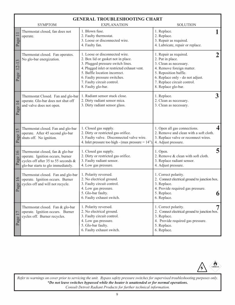
Thermostat closed, fan does notoperate.
Thermostat closed. Fan operates.No glo-bar energization.
Thermostat Closed. Fan and glo-baroperate. Glo-bar does not shut offand valve does not open.
Thermostat closed. Fan and glo-baroperate. After 45 second glo-barshuts off. No ignition.
Thermostat closed, fan & glo-baroperate. Ignition occurs, burnercycles off after 35 to 55 seconds &glo-bar starts to glo immediately.
Thermostat closed. Fan and glo-baroperate. Ignition occurs. Burnercycles off and will not recycle.
Thermostat closed. Fan & glo-baroperate. Ignition occurs. Burnercycles off. Burner recycles.
SYMPTOM EXPLANATION SOLUTION
1. Blown fuse.2. Faulty thermostat.3. Loose or disconnected wire.4. Faulty fan.
1. Loose or disconnected wire.2. Box lid or gasket not in place.3. Plugged pressure switch lines.4. Plugged inlet or restricted exhaust vent.5. Baffle location incorrect.6. Faulty pressure switches.7. Faulty circuit control.8. Faulty glo-bar.
1. Radiant sensor stuck close.2. Dirty radiant sensor mica.3. Dirty radiant sensor glass.
1. Closed gas supply.2. Dirty or restricted gas orifice.3. Faulty valve. Disconnected valve wire.4. Inlet pressure too high - (max pressure = 14”).
1. Closed gas supply.2. Dirty or restricted gas orifice.3. Faulty radiant sensor.4. Low gas pressure.
1. Polarity reversed.2. No electrical ground.3. Faulty circuit control.4. Low gas pressure.5. Glo-bar faulty.6. Faulty exhaust switch.
1. Polarity reversed.2. No electrical ground.3. Faulty circuit control.4. Low gas pressure.5. Glo-bar faulty.6. Faulty exhaust switch.
1. Replace.2. Replace.3. Repair as required.4. Lubricate, repair or replace.
1. Repair as required.2. Put in place.3. Clean as necessary.4. Remove foreign matter.5. Reposition baffle.6. Replace only - do not adjust.7. Replace circuit control.8. Replace glo-bar.
1. Replace.2. Clean as necessary.3. Clean as necessary.
1. Open all gas connections.2. Remove and clean with a soft cloth.3. Replace valve or reconnect wires.4. Adjust pressure.
1. Open.2. Remove & clean with soft cloth.3. Replace radiant sensor.4. Adjust pressure.
1. Correct polarity.2. Connect electrical ground to junction box.3. Replace.4. Provide required gas pressure.5. Replace.6. Replace.
1. Correct polarity.2. Connect electrical ground to junction box.3. Replace.4. Provide required gas pressure.5. Replace.6. Replace.
Page
11
Page
12-
13Pa
ge 1
4Pa
ge 1
5Pa
ge 1
6Pa
ge 1
6Pa
ge 1
7GENERAL TROUBLESHOOTING CHART
1
2
5
3
4
7
6
9
Refer to warnings on cover prior to servicing the unit. Bypass safety pressure switches for supervised troubleshooting purposes only.*Do not leave switches bypassed while the heater is unattended or for normal operations.
Consult Detroit Radiant Products for further technical information.

Loss of heater efficiency.
Radiant tube leaking burnt gases.
Condensation.
Tube bowing.
Tube corroding.
Visual inspection of burneroperation not possible.
Stack sooting.
Odor or fumes in space.
1. Low gas pressure.2. Dirty or restricted orifice.3. Foreign matter inside burner assembly.4. Reflector is sooted and has lost its reflective ability.5. Clogged fan blower.
1. Loose tube connections.
2. Holes or cracks in radiant tubes.
1. Stack length too long.2. Light gauge flue stack used.3. Contaminated combustion air.
1. Insufficient combustion air.
2. Contaminated combustion air.3. Overfired.4. Heater’s tubes are unable to expand.
1. Contaminated combustion air.
1. Dirty or sooted sight glass.2. Unit mounted upside down.
1. Insufficient combustion air.
2. Improper gas.
1. Vaporized solvents decomposing when contacting radiant tubes.2. Evaporation of oils/solvents at floor level.3. Fork lifts.4. Loose tube connections.
1. Provide required gas pressure.2. Remove and clean with a soft cloth.3. Clean as necessary.4. Clean with aluminum cleaner and soft cloth.5. Clean.
1. Assure that tube is fully inserted into flared end and properly clamped.2. Replace.
1. Shorten stack.2. Minimum of 26 gauge vent pipe is required.3. Provide fresh air inlet duct.
1. Provide 2 sq. in. of free air per 5000 BTU/H of input.2. Provide fresh air inlet duct.3. Check gas pressure and orifice size.4. Remount heater with 16” section of flex.
1. Provide fresh air inlet duct.
1. Remove and clean or replace.2. Mount correctly.
1. Provide 1 sq. in. of free air for every 5000 BTU/H of input.2. Correct with proper gas input.
1. Address ventilation concerns.
2. Address ventilation concerns.3. Address ventilation concerns/repair.4. Tighten tube clamps to 50-100 ft. lb.
SYMPTOM EXPLANATION SOLUTION
Page
17
Page
17
Page
18Pa
ge 1
8Pa
ge 1
9Pa
ge 1
9GENERAL TROUBLESHOOTING CHART
Page
18
Page
19
8
910
11
12
13
1415
Page
20
“How To” Instructions Inlet pressure, manifold reading, proper polarity,positive ground, negative pressure, bypass pressure switches.
10
Refer to warnings on cover prior to servicing the unit. Bypass safety pressure switches for supervised troubleshooting purposes only.*Do not leave switches bypassed while the heater is unattended or for normal operations.
Consult Detroit Radiant Products for further technical information.

Thermostat Closed, Fan Does Not Operate
If the thermostat is closed (on) and heater does not operate, check the following:
1.1Check the building’s main circuit breaker or fuse box. The problem may be a blown fuse or circuit.
1.2Thermostat Operation: Verify the thermostat is allowing power to be sent to the heater. Confirmby measuring the voltage to the heater using a volt meter (See picture below). If there is no power,the problem is in the thermostat and it should be replaced. If power is at the heater, continue on tothe next step.
1.3Check the electrical connections leading to the fan. Be sure that the wire nuts are tight.
1.4Using the voltmeter, check to be sure power is going to the fan (pg. 6, pic. 5). If there is power, trycleaning and oiling (SAE-20 oil) the motor. If the fan is still not working, it is faulty.
Picture 1.2
2 x 4 Junction Box
11
Refer to warnings on cover prior to servicing the unit. Bypass safety pressure switches for supervised troubleshooting purposes only.*Do not leave switches bypassed while the heater is unattended or for normal operations.
Consult Detroit Radiant Products for further technical information.
Solution 1

Thermostat Closed, Fan Operates, No Glo-Bar Energization(This step is applicable for all models)
2.1Locate any disconnected or loose wires and repair.
2.2The normally open Burner Pressure Switch is located on the fan side of the heater (pg. 6, pic. 1 ). This switchmust be closed before the glo-bar can be energized. *Bypass this switch (pg. 21, #6) to check for proper function.Once bypassed, reinstall the cover and test the heater. If it works, there is a problem with the burner pressureswitch or what it is sensing, and you should continue with step 2.2.1. If bypassing this pressure switch does notmake the heater work, continue with step 2.3.
2.2aBe sure the lid is on correctly and the gasket is intact.
2.2bMake sure the clear vinyl tube that bleeds pressure to the outside of the heater is clean and clear ofobstructions.
2.2cMake sure the heater’s vent cap is in place and in good condition. Also, check for obstructions within thecap.
NOTE: Excessive winds may cause properly operating safety pressure switches to shut down the heater. Heaters ductedthrough (on either the intake or exhaust sides) the roof may be deprived of the air necessary to pressurize the burner box. This“chimney effect” will typically not allow the burner pressure switch to close. Heaters vented through a sidewall may see toomuch back-pressure, thus opening the exhaust pressure switch. In either case, the caps need to be shielded to lessen the effectsof high winds.
2.2dMake sure the heater’s baffle is located properly. It should be found at the exhaust end of the emitter tube.
2.2eThe fan may not be accurately pressurizing the heater. Clean obstructions from the air-intake connectionand cap (pg. 6, pic. 8). Clean the squirrel cage. Oil the motor (SAE-20). Examine and clean the fan blades(pg. 6, pic. 5). Once the fan is completely clean, retry the heater, without bypassing the Burner PressureSwitch. If the glo-bar is still not energizing, continue with Step 2.2f.
2.2fIf steps 2.2a - 2.2f were performed and the heater still won’t properly function, the burner pressure switchis faulty.
12
Refer to warnings on cover prior to servicing the unit. Bypass safety pressure switches for supervised troubleshooting purposes only.*Do not leave switches bypassed while the heater is unattended or for normal operations.
Consult Detroit Radiant Products for further technical information.
Solution 2
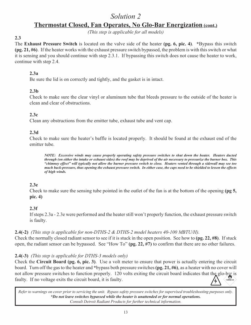
Thermostat Closed, Fan Operates, No Glo-Bar Energization (cont.)(This step is applicable for all models)
2.3The Exhaust Pressure Switch is located on the valve side of the heater (pg. 6, pic. 4). *Bypass this switch(pg. 21, #6). If the heater works with the exhaust pressure switch bypassed, the problem is with this switch or whatit is sensing and you should continue with step 2.3.1. If bypassing this switch does not cause the heater to work,continue with step 2.4.
2.3aBe sure the lid is on correctly and tightly, and the gasket is in intact.
2.3bCheck to make sure the clear vinyl or aluminum tube that bleeds pressure to the outside of the heater isclean and clear of obstructions.
2.3cClean any obstructions from the emitter tube, exhaust tube and vent cap.
2.3dCheck to make sure the heater’s baffle is located properly. It should be found at the exhaust end of theemitter tube.
NOTE: Excessive winds may cause properly operating safety pressure switches to shut down the heater. Heaters ductedthrough (on either the intake or exhaust sides) the roof may be deprived of the air necessary to pressurize the burner box. This“chimney effect” will typically not allow the burner pressure switch to close. Heaters vented through a sidewall may see toomuch back-pressure, thus opening the exhaust pressure switch. In either case, the caps need to be shielded to lessen the effectsof high winds.
2.3eCheck to make sure the sensing tube pointed in the outlet of the fan is at the bottom of the opening (pg 5,pic. 4)
2.3fIf steps 2.3a - 2.3e were performed and the heater still won’t properly function, the exhaust pressure switchis faulty.
2.4(-2) (This step is applicable for non-DTHS-2 & DTHS-2 model heaters 40-100 MBTU/H).Check the normally closed radiant sensor to see if it is stuck in the open position. See how to (pg. 22, #8). If stuckopen, the radiant sensor can be bypassed. See “How To” (pg. 22, #7) to confirm that there are no other failures.
2.4(-3) (This step is applicable for DTHS-3 models only)Check the Circuit Board (pg. 6, pic. 3). Use a volt meter to ensure that power is actually entering the circuitboard. Turn off the gas to the heater and *bypass both pressure switches (pg. 21, #6), as a heater with no cover willnot allow pressure switches to function properly. 120 volts exiting the circuit board indicates that the glo-bar isfaulty. If no voltage exits the circuit board, it is faulty.
13
Refer to warnings on cover prior to servicing the unit. Bypass safety pressure switches for supervised troubleshooting purposes only.*Do not leave switches bypassed while the heater is unattended or for normal operations.
Consult Detroit Radiant Products for further technical information.
Solution 2

Thermostat Closed, Fan & Glo-bar Operate, Glo-bar does not shut off andValve does not open
(This step is applicable for all models)3.1The normally closed radiant sensor, located on the side of the tube in the sensor box, may be stuck in the openposition. This can be confirmed by bypassing it. See how to (pg. 22, #7).
If the heater operates with the switch bypassed, the problem is with the radiant sensor or what it is sensing,therefore you should continue with step 3.1a. If bypassing the radiant sensor does not work, the valve is faulty andmust be replaced.
3.1aBe sure the radiant sensor MICA is clean and intact.
3.1bCheck to make sure the glass on the underside of the radiant sensor is clear and not cracked or broken.
3.1cReconnect the radiant sensor into the system. If steps 3.1a - 3.1b were performed and the heater will notproperly function, The radiant sensor is faulty and must be replaced.
14
Refer to warnings on cover prior to servicing the unit. Bypass safety pressure switches for supervised troubleshooting purposes only.*Do not leave switches bypassed while the heater is unattended or for normal operations.
Consult Detroit Radiant Products for further technical information.
Solution 3
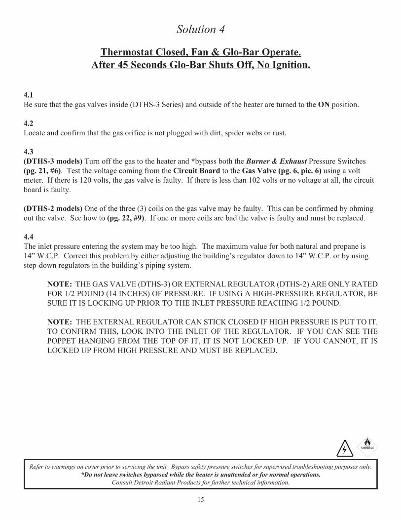
Thermostat Closed, Fan & Glo-Bar Operate.After 45 Seconds Glo-Bar Shuts Off, No Ignition.
4.1Be sure that the gas valves inside (DTHS-3 Series) and outside of the heater are turned to the ON position.
4.2Locate and confirm that the gas orifice is not plugged with dirt, spider webs or rust.
4.3(DTHS-3 models) Turn off the gas to the heater and *bypass both the Burner & Exhaust Pressure Switches(pg. 21, #6). Test the voltage coming from the Circuit Board to the Gas Valve (pg. 6, pic. 6) using a voltmeter. If there is 120 volts, the gas valve is faulty. If there is less than 102 volts or no voltage at all, the circuitboard is faulty.
(DTHS-2 models) One of the three (3) coils on the gas valve may be faulty. This can be confirmed by ohmingout the valve. See how to (pg. 22, #9). If one or more coils are bad the valve is faulty and must be replaced.
4.4The inlet pressure entering the system may be too high. The maximum value for both natural and propane is14” W.C.P. Correct this problem by either adjusting the building’s regulator down to 14” W.C.P. or by usingstep-down regulators in the building’s piping system.
NOTE: THE GAS VALVE (DTHS-3) OR EXTERNAL REGULATOR (DTHS-2) ARE ONLY RATEDFOR 1/2 POUND (14 INCHES) OF PRESSURE. IF USING A HIGH-PRESSURE REGULATOR, BESURE IT IS LOCKING UP PRIOR TO THE INLET PRESSURE REACHING 1/2 POUND.
NOTE: THE EXTERNAL REGULATOR CAN STICK CLOSED IF HIGH PRESSURE IS PUT TO IT.TO CONFIRM THIS, LOOK INTO THE INLET OF THE REGULATOR. IF YOU CAN SEE THEPOPPET HANGING FROM THE TOP OF IT, IT IS NOT LOCKED UP. IF YOU CANNOT, IT ISLOCKED UP FROM HIGH PRESSURE AND MUST BE REPLACED.
15
Refer to warnings on cover prior to servicing the unit. Bypass safety pressure switches for supervised troubleshooting purposes only.*Do not leave switches bypassed while the heater is unattended or for normal operations.
Consult Detroit Radiant Products for further technical information.
Solution 4
Thermostat Closed. Fan & Glo-Bar Operate. Ignition Occurs. Burner Cycles Off after 35 to 55 seconds & Glo-bar starts to glo immediately.
(DTHS-2 models) The glo-bar is hot enough to open the radiant sensor, but the flame is not hot enough to holdit open (see 3.1).
Take a manifold pressure to verify proper gas supply (see 4.4) (pg. 21, #2).
Solution 6Thermostat Closed. Fan & Glo-Bar Operate. Ignition Occurs.
Burner Cycles Off & will not Recycle.There are two possibilities:
1) The Burner cycles for 8 seconds and shuts off (DTHS-3 Models).
6.1The polarity could be incorrect. Check the systems wiring (pg. 21, #3) (See installation-operationmanual wiring diagram).
6.2The heater senses flame through ground. Therefore, the unit might not be properly grounded. Thewiring should be inspected (pg. 21, #4).
6.3There may be loose connections somewhere within the heater, or, the circuit board may be faulty.
6.4The gas pressure is too low. Check the manifold pressure (pg. 6, pic. 6 & pg. 21, #2) for appropriatepressure.
6.5The glo-bar may be cracked. (pg. 6, pic. 7). Check for visible damage.
2) The Burner cycles for more or less than 8 seconds and shuts off (DTHS-2 & -3).
6.6Follow steps 6.1 - 6.5.
6.7The Exhaust Pressure Switch is located on the valve side of the heater (pg. 6, pic. 4). *Bypass this switch(pg. 21, #6). If the heater works with the exhaust pressure switch bypassed, the problem is with this switchor what it is sensing and you should continue with step 2.3.1 (located on page 13). If bypassing this switchdoes not cause the heater to work, continue with step 2.4 (located on page 13).
16
Refer to warnings on cover prior to servicing the unit. Bypass safety pressure switches for supervised troubleshooting purposes only.*Do not leave switches bypassed while the heater is unattended or for normal operations.
Consult Detroit Radiant Products for further technical information.
Solution 5

Solution 7
Thermostat Closed. Fan & Glo-Bar Operate. Ignition Occurs. Burner Cycles Off. Burner Recycles.
Refer to steps 6.6 - 6.7.
Solution 8
Heater’s Efficiency is LackingUsually, a heater lacking in efficiency has improper gas pressure, dirty parts or is a misapplication of the heateritself.
8.1If the manifold pressure is not high enough, ( 3.8” natural for 40-125 MBH, 6.0” natural for 150 MBH and 10”for propane) the heater will not deliver the desired amount of heat. Check the Manifold Pressure (pg. 6, pic. 6)and pg. 21, #1 & #2).
8.2Locate and confirm the orifice is not plugged with dirt, spider webs or rust.
8.3Check the burner assembly to make sure it is clear of any obstructions.
8.4Be sure the reflector is in place and clean. Use a soft cloth and aluminum cleaner to clean the reflector.
8.5Be sure the fan is clean and able to supply the appropriate amount of air to the heater. Clean any obstructions fromthe air-intake pipe and cap. Clean the squirrel cage. Oil the motor (SAE-20). Examine and clean the fan blades.
17
Refer to warnings on cover prior to servicing the unit. Bypass safety pressure switches for supervised troubleshooting purposes only.*Do not leave switches bypassed while the heater is unattended or for normal operations.
Consult Detroit Radiant Products for further technical information.
Solution 9
Radiant Tube Leaking Burnt Gas
Obstructions in the heater may cause too much heat in a specific point, leading to holes or cracks. Theseopenings can cause burnt gas to leak out. If this problem is occurring, follow these steps:
Carefully inspect the length of all emitter tubes and clamps for any cracks, holes or loose connections. If anypart of the tube has an opening, it must be replaced immediately. Also check for blockages in the exhaust andemitter tube.
Solution 10
Condensation is Forming
If condensation is forming anywhere along the length of the emitter or exhaust pipe, check to make sure that itis not excessive in length. Be sure that the heater has the appropriate manifold pressure (Tow To part 2).Confirm the use of adequate vent material (26 gauge minimum is required). Inspect the baffle location (itshould be found at the exhaust end of the emitter tube), insulate vent materials, and seal leaks around ventopenings. Chemicals burned through the combustion process can alter the exhaust by-products andtemperature. See your heater’s manual for air-intake specifications.
Solution 11
Emitter Tube is Bowing
Normal operation of the heater will often cause expansion of the emitter tube. If there is no room for this tooccur, the tube will bow. If this is happening, follow steps below.
11.1Too little air will lead to shorter flame, causing it to burn hotter than normal. Be sure there is nothing blockingthe air intake and that the fan is clean (pg. 6, pics. 5 & 8).
11.2Contaminated combustion air could alter the flame characteristics, overheating the tube and causing it to bow.See your manual for air-intake specifications.
11.3Too much gas may also overheat the tube and cause it to bow.Check the manifold (How To part 2) pressure (pg. 6,pic. 6).
11.4If the heater is mounted so that it cannot expand lengthwise (ie. it is cemented into the wall at both ends), add a16” section of flex on the inlet side of the heater and allow the exhaust to move freely through the wall.
Solution 12
Tube is Corroding
The tube would corrode if the air entering the heating system was not clean. See your heater’s manual forcombustion air intake instructions.
18
Refer to warnings on cover prior to servicing the unit. Bypass safety pressure switches for supervised troubleshooting purposes only.*Do not leave switches bypassed while the heater is unattended or for normal operations.
Consult Detroit Radiant Products for further technical information.

Solution 13
Visual Inspection of Burner Operation not Possible
From the ground, the burner inspection window should be visible. If it is not, the heater may be mounted upsidedown. Confirm proper mounting and remount if necessary.
Solution 14
Stack Sooting
Soot accumulation can be caused by the following:
14.1If the air entering the system is not clean (see solutions 6 & 8), soot will form.
14.2Soot will form if there is not enough air entering the system. The air intake orifice and pipe must be clean andclear of any obstructions (see 2.2e) (pg. 6 pic. 8).
14.3Too much gas entering the system will cause soot to form. Check the manifold (section 6.1) pressure(pg. 6, pic.6 and pg. 21, #2) for the appropriate pressure.
14.4Check the atmospheric vents on both pressure switches to be sure they are clean and clear. (see 2.3b).
14.5Be sure there is no excessive back pressure on the system. (Example - high winds, bird nest, snow, etc.)
Solution15Odor or Fumes Present in Space
Odors present in the space being heated may be caused by a variety of products being used, stored or processedin the space. These are usually cleaning solvents or sealers which are high in hydrocarbons (ie. parts cleaners,transmission cleaners and floor sealers). In addition, propane burning forklifts can also add odors and carbonmonoxide to the space.
To cut down on these odors, a clean work environment has to be maintained. If it is necessary that thesesolvents remain in the space, proper ventilation is required.
NOTE: If the heater is pulling intake air from the space, its integrity can be compromised by the presence of these solvents, causing the same problems found in solutions 8-12 of this guide.
19
Refer to warnings on cover prior to servicing the unit. Bypass safety pressure switches for supervised troubleshooting purposes only.*Do not leave switches bypassed while the heater is unattended or for normal operations.
Consult Detroit Radiant Products for further technical information.

Mod
elYe
arFa
nBu
rner
Sw
itch
Exha
ust
Sw
itch
Sens
or/
Circ
uit
Boar
dG
lo-B
arRe
gula
tor
Val
veM
anifo
ld
Pres
sure
Tube
s
DTH
NOV
. 86
&
PR
IOR
TP-5
5TP
-61
TP-6
0TP
-64
TP-5
0N)
TP-
33
P) T
P-33
PTP
-36
N) 3
.8"
P) 1
0.0"
TP-8
SUB
TP-
8B 1
00M
BH.
N A
ND B
ELO
W. T
P-8D
100
MBH
. P.
DTHS
1984
&
PRIO
RTP
-55
TP-6
1TP
-60
TP-6
4TP
-50
N) T
P-33
P)
TP-
33P
TP-3
6N)
3.8
"
P)
10.
0"
16 IN
CH
TUBE
: TP
-6 S
UB T
P-6A
.
10
FO
OT
TUBE
: TP
-26
SUB
TP 2
6A 1
00M
BH. N
AND
BEL
OW
, TP
-26B
100
MBH
. P.
DTHS
1985
TO
NOV
. 86
TP-5
5TP
-61
NONE
TP-6
4TP
-50
N) T
P-33
P)
TP-
33P
TP-3
6N)
3.8
"
P)
10.
0"
16 IN
CH
TUBE
: TP
-6 S
UB T
P-6A
.
10
FO
OT
TUBE
: TP
-26
SUB
TP 2
6A 1
00M
BH. N
AND
BEL
OW
, TP
-26B
100
MBH
. P.
DTH(
S)-2
NOV
. 86
TO
JA
N. 8
7TP
-55A
TP-6
1ATP
-60
TP-6
4TP
-50
N) T
P-33
P)
TP-
33P
TP-3
6N)
3.8
"
P)
10.
0"
DTH:
TP-
8B 1
00M
BH. N
AND
BEL
OW
. TP-
8D 1
00M
BH. P
.
DT
HS: 1
6 IN
CH
TUBE
: TP6
A 1
0 FO
OT
TUBE
: TP2
6A 1
00M
BH.
N A
ND B
ELO
W T
P-26
B 10
0MBH
. P.
DTH(
S)-2
JAN.
87
TO
A
PR. 9
2TP
-55A
TP-6
1ATP
-60A
TP-6
4TP
-50
N) T
P-33
P)
TP-
33P
TP-3
6N)
3.8
"
P)
10.
0"
DTH:
TP-
8B 1
00M
BH. N
AND
BEL
OW
. TP-
8D 1
00M
BH. P
.
DT
HS: 1
6 IN
CH
TUBE
: TP6
A 1
0 FO
OT
TUBE
: TP2
6A 1
00M
BH.
N A
ND B
ELO
W T
P-26
B 10
0MBH
. P.
DTH(
S)-2
APR
. 92
TO
JA
N 00
TP-5
5ATP
-61B
TP-6
0CTP
-64
TP-5
0N)
TP-
33
P) T
P-33
PTP
-36
N) 3
.8"
P) 1
0.0"
DTH:
TP-
8B 1
00M
BH. N
AND
BEL
OW
. TP-
8D 1
00M
BH. P
.
DT
HS: 1
6 IN
CH
TUBE
: TP6
A 1
0 FO
OT
TUBE
: TP2
6A 1
00M
BH.
N A
ND B
ELO
W T
P-26
B 10
0MBH
. P.
DTH(
S)-2
125,
150
MBH
1988
TO
1989
TP-5
5ATP
-61A
TP-6
0BTP
-77
TP-5
0N/
ATP
-36
(A,B
,C)
125
N) 3
.8"
12
5 P)
10.
0"
150
N) 6
.0"
15
0 P)
10.
0"
DTH:
TP-
8B 1
00M
BH. N
AND
BEL
OW
. TP-
8D 1
00M
BH. P
. 12
5 A
ND 1
50M
BH. N
OR
P.
DTHS
: 16
INC
H TU
BE: T
P6A
10
FOO
T TU
BE: T
P26A
100
MBH
. N
AND
BEL
OW
TP-
26B
100M
BH. P
. 125
AND
150
MBH
N O
R P.
DTH(
S)-3
12
5, 1
50M
BH
1989
TO
1994
TP-5
5ATP
-61A
SUB
TP-6
1B
TP-6
0B
SU
B
TP
-60D
TP-7
8A
W
/TP-
78B
TP-5
0N/
A
125N
: TP-
107
125P
: TP-
107P
150N
: TP-
79
150P
: TP-
79A
126
N) 3
.8"
12
5 P)
10.
0"
150
N) 6
.0"
15
0 P)
10.
0"
DTH:
TP-
8B 1
00M
BH. N
AND
BEL
OW
. TP-
8D 1
00M
BH. P
. 12
5 A
ND 1
50M
BH. N
OR
P.
DTHS
: 16
INC
H TU
BE: T
P6A
10
FOO
T TU
BE: T
P26A
100
MBH
. N
AND
BEL
OW
TP-
26B
100M
BH. P
. 125
AND
150
MBH
N O
R P.
DTH
/ D
THS
Hist
ory
20

HOW TO...
1 - Take an Inlet Pressure Reading: (Always take the inlet pressure before taking the manifold pressure)
¨ Follow the same procedures as taking a Manifold Pressure Reading (Step 2 below) except usethe inlet tap on the gas valve or the gas cock, located on the outside of the heater.
2 - Take a Manifold Pressure Reading:
¨ Turn gas and power to the heater off.¨ Remove lid.¨ Locate outlet tap on gas valve (pg. 6, pic. 6).¨ Remove tap using a 3/16” allen wrench.¨ Insert a 1/8” pipe-thread barb fitting and run a hose to the outside of the burner box using the
5/16” capped hole next to the gas valve line opening, or, the 3/8” hole next to the conduit goingto the glo-bar box (newer models only).
¨ Connect tube to a Manometer or Magnahelic.¨ Reinstall lid.¨ Fire heater.¨ The reading on the Manometer or Magnahelic is the manifold pressure.
3 - Check for Proper Polarity:
¨ Turn off power to the heater.¨ Remove the cover of the 2x4 junction box on the outside of the heater - if applicable.¨ Locate the three wires inside - black, white & green.¨ Using a voltmeter, touch the black wire with one probe and the green wire with the other -
confirm 120V.¨ Using a voltmeter, touch the white wire with one probe and the green wire with the other -
confirm 0.0V.¨ If the previous step confirmed 120V, the polarity is reversed and must be corrected in the conduit
upstream from the heater.
4 - Test for Positive Ground:
¨ Be sure that the ground (green) wire goes all the way back to the circuit panel.¨ If it does not, a qualified electrician must rerun this line.
5 - Test for Negative Pressure:
The building has a negative pressure if any of the following is occurring:
¨ Building’s door(s) shut very quickly with a loud bang.¨ Building’s door(s) are difficult to open - as if they are suctioned shut.¨ The heater is fired and then turned off. The lid is removed and hot gases come
back into the heater box.¨ An incline manometer is set up with one hose outside of the building and one inside.
It’s reading confirms a negative inside pressure.
6 - Bypass a Switch:
¨ Turn power off.¨ Disconnect both black wires attached to the safety switches with a 1/4” female spade.¨ Attach them to each other using alligator clips or electrical tape.¨ Be sure this connection touches nothing else, especially metal.¨ Turn power back on (Do not leave switches bypassed during normal heater operation).
21

HOW TO...
7- Bypass a Radiant Sensor:
¨ Turn off the power to the heater.¨ Remove the cover on the radiant sensor box.¨ Disconnect the black and white wire from the radiant sensor and connect them together. (WARNING:
there will be 120 volts at these two wires so they can not be touching you or anything else.)¨ Turn on the power to the heater and let the glo-bar heat up for one minute.¨ Disconnect the two wires, if the heater fires and keeps firing up until the thermostat is satisfied the
radiant sensor may be bad or the sensor mica may be dirty. (WARNING: there will be 120 volts atthese two wires so they can not be touching you or anything else.)
8- Checking a Radiant Sensor for continuity:
¨ Turn off the power to the heater.¨ Remove the cover on the radiant sensor box.¨ Disconnect the black and white wire from the radiant sensor. (WARNING: there will be 120 volts at
these two wires so they can not be touching you or anything else.)¨ Using a multi-meter measure across the normally closed switch, if it is open then the radiant sensor is
bad.
9- Ohming out the WR 25K valve:
¨ Turn off the power to the heater.¨ Remove the cover on the radiant sensor box.¨ Disconnect the black and white wire going to the radiant sensor (WARNING: there will be 120 volts at
these two wires so they can not be touching you or anything else.), at the white or orange wirenuts.Disconnect the black valve wire going to the pressure switch, the red neutral wire, and the two red glo-bar wires, at the plug.
¨ Using a muli-meter measure the ohm reading across the red(-) and black(+) on the valve. If the readingis 567-694 ohms the coils are good, if 1100-1430 one or more coils are bad and valve must be replaced.
10- Enlarge the Radiant Sensor hole:
¨ Turn off the power to the heater.¨ Remove the cover on the radiant sensor box.¨ Disconnect the black and white wire from the radiant sensor and remove the sensor and mica.¨ If the hole is ¼” x 1” it will have to be enlarged to 5/8” x 1 ¼”. This is best accomplished by using a
die grinder. Note: If using any tool that penetrates the tube more than ¼” remove the glo-bar as not todamage it.
22

HOW TO...
11- Installing a TP-CPA-2 on a single pressure switch straight tube.
¨ Turn off the power to the heater.¨ Remove the burner box lid.¨ Disconnect the wires going to the fan, door switch and pressure switch(s) along with the white neutral
wire going to the red neutral on the gas valve.¨ Remove the door switch.¨ Remove the 6 screws that hold the center panel in the burner box, then remove the center panel along
with the fan and pressure switch still attached.¨ Install the new center panel using the old screws.¨ Rewire the heater according to the wiring diagram on page 3.¨ On the front panel of the burner box (same side that the emitter tube is attached to) there are two bolts
with nuts. One bolt is plugging a hole in the fan compartment the other is plugging a hole in the valvecompartment. Remove these bolts and discard.
¨ Align the vinyl tube from the atmospheric side of the pressure switch in front of the hole and install thebrass barb fitting from the outside of the box.
¨ Install the burner box lid and turn power to heater back on.
23
CPA-2
Burner Switch& Fan
Exhaust Switch& Fan
Buner BoxTop View