tube-line bale processor boss i
TRANSCRIPT
Operator's Manual
Tube-Line Bale Processor
Boss I
29656 (01/26/12)

2

3
TUBE●LINE Manufacturing
3928 Steffler Road RR# 4
Elmira, ON N3B 2Z3 Canada
1-888-856-6613 Fax 519-664-0492
[email protected] www.tubeline.com
Owner and Operator and Safety Information …………………….....3-6
Definitions of Safety Terms and Symbols, Accident Prevention ….....3
Safety Instructions …………………………………………………......4-5
Safety Signs ......................................................................................6
Power Unit Specifications ………………………………….………..…..7
Installation Instructions ……………………………………...…..….……7
Hydraulic Instructions …………………………………………….….…..7
Operation …………………………………………………………..….….8
Maintenance ……………………………………………………….……..9
Service ……………………………………………………………...……..9
Grease Points …………………………………………………….……..10
Deck Assembly …...………………………………….………...….….…11
Top Beater Assembly …………………………………………....…..….12
Bottom Beater Assembly……………………………………………..…13
Ram Assembly ………………………………….………………….....…14
Hydraulic Schematic ……………………………………………….…...15
Warranty Policy………………………………………….….……...….…16
Table of Contents

4
INTRODUCTION
Thank you for purchasing your new Boss I square bale processor. Your Boss I was designed to load and shred all types of forage in large square bales up to 1500 pounds (680 kg). Maximum length of bales is 84” (213 cm) X 36” (91 cm) X 36” (91 cm) The Boss I square bale processor has multiple uses: Laying windrows in open fields. Filling feed bunks – fence line, circular, etc. Spreading forage for livestock bedding. Spreading mulch over perennial plants such as strawberries and mushrooms. The Boss I was carefully designed and manufactured to give you many years of dependable service. You or any other person, who will be assembling, operating, maintaining or working with this product, are required to read and completely understand the information and instructions contained in this manual. If anyone does not fully understand every part of this manual, please obtain further assistance by contacting the dealer from which this product was purchased or by contacting Tube·Line at the telephone number or address listed on the previous page of this manual. Keep this manual available for reference whenever this product is being handled or used. Provide this manual to any new owners and/or operators.
GENERAL INFORMATION The purpose of this manual is to assist you in safely assembling, mounting, operating and maintaining your Boss I. Read this manual carefully to obtain valuable information and instructions that will help you achieve safe and dependable service. The illustrations and data used in this manual were current at the time of printing, but due to possible engineering and/or production changes, this product may vary slightly in detail. Tube·Line reserves the right to redesign and/or change components as necessary without notification.
Throughout this manual, references may be made to:
Power Unit The engine-driven machine to which this product must be attached.
Right, Left, Front, Rear
Directions which are determined in relation to the operator of the equipment when seated in the normal operating position.
IMPORTANT Precautions that must be followed to prevent damage to equipment.
NOTICE Precautions that must be followed to prevent substandard performance.
SERIAL NUMBER LOCATION Always refer to the model and serial number when ordering parts or requesting information from your dealer. The serial number plate is located on upper left front corner of the tub of your Boss I. Refer to diagram on page 6.

5
DEFINITION OF SAFETY TERMS AND SYMBOLS
Throughout this manual, the terms DANGER, WARNING and CAUTION are used to indicate the degree of hazard to personnel if proper safety procedures are not followed.
These words will be used in conjunction with the Safety Alert Symbol: a dark triangle containing a white exclamation mark.
The Safety Alert Symbol means: - ATTENTION! - BECOME ALERT! - YOUR SAFETY IS INVOLVED!
DANGER Indicates an imminently hazardous situation, which, if not avoided,
WILL result in death or serious injury. WARNING Indicates a potentially hazardous situation, which, if not avoided,
Could result in death or serious injury. CAUTION Indicates a potentially hazardous situation, which, if not avoided,
May result in minor or moderate injury; OR
May also be used to alert against unsafe practices, which may result in damage to property.
The safety information given in this manual does not replace any safety codes, insurance needs, federal, state and local laws.
ACCIDENTS CAN BE PREVENTED WITH YOUR HELP!
The best safety device is a careful operator. Tube·Line and your dealer ask that YOU be that careful, responsible equipment operator. Pay attention to the job at hand. Do not let your mind lose concentration on what you are doing. No accident prevention program can be successful without the wholehearted cooperation of the person who is directly responsible for the operation of the equipment. If accidents are to be prevented (and accidents can be prevented), that prevention will come from equipment operators who accept their complete responsibility and anticipate the results of their actions. The designer, the manufacturer, and the safety engineer all help create a safe product, but their combined efforts can be wiped out with a single careless act by the operator of that product. Do not attempt to operate this equipment under the influence of drugs or alcohol.
YOU ARE THE KEY TO SAFETY BECAUSE: YOU are responsible for the SAFE operation and maintenance of YOUR Side Discharge Bucket. YOU are responsible to familiarize yourself, and anyone else who will assemble, operate, maintain, or work around this product, with the safety information contained in this manual. YOU are responsible to read ALL information contained in this manual to any operators or maintenance personnel who are not fully able to read the written English language. Whether YOU read the manual as written or translate it into another language, YOU must make certain that all operators and maintenance personnel have complete understanding of the full and exact contents of this manual. YOU can reduce the risk of injury or death by following all safety precautions and by using good safety practices.

6
Safety Instructions WORK SAFELY – A CAREFUL OPERATOR IS THE BEST INSURANCE AGAINST
ACCIDENTS!!
SECTION 1 WARNING SECTION
WARNING Obey all safety instructions listed in this section and throughout this manual. Failure to obey instructions in this section could result in death or serious injury.
BEFORE ATTEMPTING ANY TYPE OF ASSEMBLY, OPERATION, MAINTENANCE OR OTHER WORK
ON OR NEAR THIS PRODUCT: READ AND COMPLETELY UNDERSTAND THIS MANUAL. READ AND COMPLETELY UNDERSTAND THE MANUALS PROVIDED WITH YOUR POWER UNIT, LOADER AND QUICK-ATTACH. Read and understand all safety signs on this product and on your power unit, loader and quick-attach. Know all your controls and know how to quickly stop all power unit movements, the processor movement, and the engine in case of emergency. Know and obey all applicable government rules, O.S.H.A regulations, local laws and other professional guidelines for your operation. Make sure that anyone who will be assembling, mounting, maintaining, repairing, removing and/or storing this product: Has been instructed in the safe operation of this product and of the power unit and the quick-attach to which this product is attached. Is physically and mentally capable of the safe operation of this type of equipment. Is not under the influence of drugs or alcohol. Is carefully supervised from a safe distance, especially if such person is inexperienced. Wears personal protective equipment (i.e. hardhat, safety glasses, work gloves, protective shoes, respirator, ear protection, etc.) Does not wear loose fitting clothes, loose or uncovered hair or any accessories (jewelry, necktie, scarf, wrist watch, etc.) that can catch and entangle on moving parts. Has annually reviewed all safety instructions. Know and follow good work practices when assembling, mounting, maintaining, repairing, removing and storing this product: Work on a level surface in a well lit area. Keep the area clean and dry. Use properly grounded electrical outlets and tools. Use the right tool for the job at hand. Make sure that your tools are in good condition for performing the desired function. When using tools, wear the protective equipment specified by the tool manufacturer (i.e. hardhat, safety glasses, work gloves, protective shoes, etc.). WHEN YOUR POWER UNIT IS USED DURING ANY TYPE OF ASSEMBLY, OPERATION, MAINTENANCE OR OTHER WORK ON OR NEAR THIS PRODUCT: Before leaving the operator’s station or before beginning any type of work on this product, lower this product to the ground, apply your power unit’s parking brake, stop the engine, remove the starter key, wait for all moving parts to stop and then relieve all pressure in the hydraulic lines. Refer to your power unit’s operator’s manual for instructions on how to relieve hydraulic pressure in lines. Know your loader’s safe lifting and operating capacity and the weight of this product. See the specifications in this manual for the weight of this product and refer to your power unit’s and loader’s operator’s manuals for safe operating limits. Lift capacity may be reduced if using a quick-attach. Never allow anyone, except the operator, to be around the power unit or this product when either is in motion. Do not start up unless others are clear of the work area. Do not allow riders on this product or the power unit. Do not stand or climb on this product when raised. Do not place any part of your body under any part of this product unless this product is securely resting on adequate blocking or on the ground. Do not use blocking made of concrete blocks, logs, buckets, barrels or any other material that could suddenly collapse or shift positions. Do not use wood or steel blocking that shows any signs of material decay. Do not use wood blocking that is warped, twisted or tapered. Never operate controls from the ground. Operate the controls only from the operator’s station. Never leave the equipment unattended with the engine running or with this product raised on the loader. Be aware of the added weight and width of this product. Reduce travel speeds accordingly, especially when traveling over rough ground. Keep this product close to the ground and under control when transporting. When transporting, be sure processor
does not block view of vehicle lights or road.

7
WARNING SECTION [Continued] WARNING
Obey all safety instructions listed in this section and throughout this manual. Failure to obey instructions in this section could result in death or serious injury. WHEN DEALING WITH HYDRAULICS DURING ANY TYPE OF ASSEMBLY, OPERATION, MAINTENANCE OR OTHER WORK ON OR NEAR THIS PRODUCT: Hydraulic fluid under pressure can penetrate the skin and cause serious injury or death. Hydraulic leaks under pressure may not be visible! If any fluid penetrates the skin, GET IMMEDIATE MEDICAL ATTENTION!! Wear safety glasses, protective clothing and use a sound piece of cardboard or wood when searching for hydraulic leaks. DO NOT USE YOUR HANDS! Before connecting or disconnecting hydraulic hoses, read your tractor or power unit’s operator’s manual for detailed instructions on connecting and disconnecting hydraulic attachments. Make certain that all parts meet the specifications for this product when installing or replacing hydraulic hoses or fittings. After connecting hydraulic lines: Slowly and carefully raise the loader and cycle the rollback / dump cylinders to check hose clearances and to check for any interference. Operate the hydraulics on this product to check hose clearances and to check for any interference. Make certain that the hoses cannot interfere with or actuate the quick-attach mechanism. Make certain that hoses will not be pinched, or get tangled, in any equipment. Do not lock the auxiliary hydraulics of your power unit in the “ON” position. Refer to your power unit’s operator’s manual and this manual for procedures and intervals, then inspect and maintain the entire hydraulic system to insure that the fluid remains cleans, that all devices function properly and that there are no fluid leaks. WHEN MOUNTING THIS PRODUCT TO YOUR POWER UNIT: Refer to the operator’s manuals of your power unit, your loader and your quick-attach for special or detailed mounting instructions. This product should fit onto the quick-attach or loader arms of your power unit the same as the original products that were designed by your loader / quick-attach manufacturer. If this product does not fit properly, contact Tube·Line before operating. Never place your finger into the mounting plate or 3-point hitch or loader holes. A slight movement of the power unit or this product could cause serious injury. Make certain that all safety signs are in place and legible. Refer to the safety sign page in this manual for the placement of safety signs for this product. Inspect driveline shield for free rotation. Replace all damaged or excessively worn parts and hardware only with genuine Tube·Line parts or with properly rated fasteners, hydraulic hoses or fittings. Make certain that all locking pins, latches and connection devices are properly installed and secured. Make certain that all shields are in place and secure. Remove all foreign objects from processor. Never use processor on a power unit that is not equipped with a cab or ROPS, and operator restraints (seat belts or equivalent devices). Make sure bales are free from foreign objects. Drive slowly through gates and doors. Know your loader’s safe operating weight limit and the weight of your loader attachment. WHEN ADJUSTING, SERVICING OR REPAIRING THIS PRODUCT: Make no modifications to your processor. When making repairs, use only genuine Tube·Line parts or, for fasteners, hydraulic hoses or hydraulic fittings, use only properly rated parts. Replacement parts, for parts with safety signs attached, must also have safety sign attached.
Think SAFETY! Work SAFELY!

8
SAFETY SIGN LOCATIONS
PLACEMENT OR REPLACEMENT OF SAFETY SIGNS
Clean the area of application with non-flammable solvent, then, wash the same area with soap and water. Allow the surface to fully dry. Remove the backing from the safety sign,
exposing the adhesive surface. Apply the safety sign to the position shown in the diagram above and smooth out any bubbles.
INSTRUCTIONS
Keep all safety signs clean and legible. Replace all missing, illegible or damaged safety signs.
Replacement parts for parts with safety signs attached must also have safety signs attached. Safety signs are available free of charge from your dealer or from Tube-Line.
Item : 1 Part # : DE23839
Item : 3 Part # : DE23848 Item : 2
Part # : DE23847

9
Item : 6 Part # : DE23850
Item : 7 Part # : DE23840
Item : 4 Part # : DE23845 Item : 5
Part # : DE23837

10
POWER UNIT SPECIFICATIONS
IMPORTANT Exceeding any of the recommended power unit specifications CAN result in damage to your power unit and/or this product and
WILL void all Tube·Line warranties.
Minimum Maximum
20GPM at 2500PSI 40GPM at 3000PSI
PROCESSOR INSTALLATION INSTRUCTIONS
Place this product on a firm, level surface that is large enough to safely accommodate this product, your power unit and all workers involved in the mounting process. Be sure all connection points are properly secured. Refer to the operator’s manual(s) for your power unit, loader and quick-attach and follow the mounting instructions contained therein. Carefully raise the loader arms and cycle the tilt cylinders to check clearances and to verify that all mounting procedures have been successfully completed.
SAFETY FIRST!! READ AND UNDERSTAND THE SAFETY INSTRUCTIONS (pages 3-6 of this manual) BEFORE BEGINNING ANY PROCESSOR MOUNTING.
Processor Hydraulic Connection
SAFETY FIRST!! READ AND UNDERSTAND THE SAFETY INSTRUCTIONS (pages 3-6 of this manual) BEFORE BEGINNING ANY HYDRAULIC CONNECTION.
Disconnect the hydraulic hose quick couplers from one another and attach the quick couplers to your power unit as per the instructions in your power unit’s operator’s manual. Carefully raise the loader arm and cycle the tilt cylinders to check hose clearances and to check any interference.
WARNING Do not lock the auxiliary hydraulics of your tractor or power unit in the “ON” position.
Failure to obey this warning could result in death or serious injury.

11
PROCESSOR OPERATION
SAFETY FIRST!! READ AND UNDERSTAND THE SAFETY INSTRUCTIONS (pages 3-6 of this manual) BEFORE BEGINNING ANY
PROCESSOR OPERATION.
DANGER Failure to obey the following procedure will result in death or serious injury. Avoid contacting overhead wires.
WARNING Failure to obey the following procedures could result in death or serious injury. Never lift this product: above the operator’s eye level OR to a height where visibility is obstructed, whichever is lower. Use caution when raising loaded processor. Objects could fall from processor toward bystanders or operator. Remove all foreign objects from bales.
NOTICE Refer to your power unit’s operator’s manual for safe operating limit and use of counterweights.
To Load: Load one bale at a time. If bales are frozen, put frozen side down to the table for better operation. Center the bale on the forks before loading on to the table. Slide forks lightly on the ground when loading bales. Store bales on level ground and on a clean surface free from rocks and other foreign objects. - Adjust discharge deflector to spread forage at desired width. - Operating power unit at maximum R.P.M. allows the processor to do a better job of chopping forage. - Twine build - up should be kept to a minimum to reduce fire hazard and keep the machine in balance. - Always lower the processor to the ground; set the parking brake; stop the engine; remove ignition key and wait for all moving parts to stop before leaving the operator’s seat.

12
PROCESSOR MAINTENANCE
Regular maintenance is the key to long equipment life and safe operation. It is very important that these maintenance functions be performed as described below.
SAFETY FIRST!! READ AND UNDERSTAND THE SAFETY INSTRUCTIONS (pages 3-6 of this manual) BEFORE BEGINNING ANY PROCESSOR MANTENANCE OPERATION
IMPORTANT The flail tube on this machine is a fully balanced assembly. If for any reason the flails must be removed, they must be returned to the same position they were taken from. If this is not done a balance problem will result in causing machine vibration. Number flails and inserts and their positions before you do any work.
BEFORE FIRST USE Inspect the attachment for shipping damage. If damage does exist, do not operate until the damaged parts have been replaced or repaired.
BEFORE EACH USE
Check for loose or badly worn parts. Conveyor chain should be adjusted to allow chain slack 1” (2.54 cm) to 1½” (3.8 cm). Make sure that all hydraulic fittings are tightened and that there are no leaks in any fittings or hoses. Inspect rotor and all rotating parts for twine or wire build-up. Check for cylinder wear and broken flails and flail bracket wear. Replace with new “Boss” flails to keep machine in balance. Make sure that all safety signs are in place, are clean and are legible. SEE THE SAFETY SIGN SECTION (page 6)
AFTER EVERY 10 HOURS OF OPERATION Grease all roller bearings. (refer to diagram on page 10) Inspect and tighten Allen screws on bearing.
PROCESSOR SERVICE
SAFETY FIRST!! READ AND UNDERSTAND THE SAFETY INSTRUCTIONS (pages 3-6 of this manual) BEFORE BEGINNING ANY PROCESSOR SERVICE.
WARNING Hydraulic fluid under pressure can penetrate skin, resulting in serious injury or death. Always relieve hydraulic pressure before disconnecting lines.
Shut off engine, set parking brake and relieve hydraulic pressure before connecting or disconnecting hydraulic lines. Refer to your power unit’s manual for instruction on how to relieve hydraulic pressure in lines. Before applying pressure to the system, be sure that all connections are tight and be sure there are no damaged hoses, lines or fittings. Wear safety glasses and use metal or wood when searching for leaks. Do not use your hands.
WARNING Before servicing the loader, remove the attachment and make certain the lift arms are lowered to their lowest position or that the arms are supported by the mechanical lock up devices (if the machine is so equipped).
Steam-clean the power unit before any installation is made to the hydraulic system. Remove any attachment from the power unit and position on a level surface.

13

14
Dec
k A
ss
em
bly

15
Deck Assembly
Item Qty Part # Description
1 1 B1 Deck 8 Deck Weldment
2 1 B1 089 Ram/Chain Attachment
3 1 B1 150 Ram
4 1 B1 123 Bottom Ram Slider Plate
5 2 B1 083 Bearing Guard
6 2 BEA UCF207-20 Bearing
7 8 FW 1/2 Flat Washer
8 8 LW 1/2 Lock Washer
9 8 HB 1/2 X 2 Hex Bolt
10 22 FW 5/8 Flat Washer
11 3 LW 5/8 Lock Washer
12 9 HB 5/8 X 2 Hex Bolt
13 2 HB 5/8 X 2.25 Hex Bolt
14 3 HN 5/8 Hex Nut
15 9 HB 3/8 X 1 Hex Bolt
16 1 B1 079 Adjuster Bracket
17 5 LW 3/8 Lock Washer
18 1 HN 3/8 Hex Nut
19 1 BS200141A Sprocket Assembly
20 1 BS200138A Chain Drive Sprocket
21 1 B1 082 Chain Tightener
22 1 SPR60B30F-IH Sprocket
23 4 BS199398A Drive Sprocket Bearing
24 8 LW 5/8 Lock Washer
25 2 FW 5/8 Flat Washer
26 2 LN 5/8 Lock Nut
27 3 LA-MFE43 Tine
28 1 B1 122 Ram Guide
29 1 VAL 1008 Motor
30 1 SPR60B11 Sprocket
31 1 25783 Loading Plate
32 1 26050 Bale Guide
33 1 26051 Bale Guide Spacer
34 1 VAL 1002 Bottom Beater Motor

16
To
p B
ea
ter
As
se
mb
ly
Use
d u
p to
se
ria
l #
10
B1
06
1

17
Top Beater Assembly
Used up to serial # 10B1 061
Item Qty Part # Description
1 1 25509 Top Beater Chain Shield
2 1 B1 080 Top Beater Side Plate
3 2 B1 084 Top Beater
4 1 B1 103 Top Beater Motor Mount
5 4 BEA PF205 Bearing
6 1 B1 081 Front Shield
7 1 B1 060 Top Beater Side Plate
8 38 LW 3/8 Lock Washer
9 15 HB 3/8 X 1 Hex Bolt
10 13 LN 3/8 Lock Nut
11 12 LN 5/16 Lock Nut
12 8 HB 3/8 X 1.5 Hex Bolt
13 6 FW 3/8 Flat Washer
14 4 HN 3/8 Hex Nut
15 1 B1 077 Rubber Deflector
16 1 B1 075 Rubber Deflector Mount
17 3 HIN 3.5 X 3.5 Hinge
18 8 CB 1/4 x 1 Round Head Bolt
19 14 HN 1/4 Hex Nut
20 14 LW 1/4 Lock Washer
21 6 CB 1/4 X .75 Round Head Bolt
22 1 25576 Top Beater Shield
23 1 VAL 1008 Motor
24 2 SPR5014F-1 14 Tooth Sprocket
2 Square Keys are 1/4” x 2 1/2”
VAL MLHPQ400C4C

To
p B
ea
ter
As
se
mb
ly
Use
d fro
m s
eria
l #
12
B1
00
1 to
cu
rre
nt
18

19
Top Beater Assembly
Used from serial # 12B1 001 to current
Item Qty Part # Description
1 1 25576 Top Beater Chain Shield
2 1 25786 Middle Guard
3 1 28783 Top Guard Lid
4 1 B1 060 Top Beater Side Plate
5 1 B1 075 Rubber Deflector Mount
6 1 B1 077 Rubber Deflector
7 1 B1 080 Top Beater Side Plate
8 1 B1 081 Front Shield
9 2 B1 084 Top Beater
10 1 B1 103 Top Beater Motor mount
11 4 BEA PF205 Bearing
12 8 CB 1/4 X 1 Carriage Bolt
13 6 FW 3/8 Flat Washer
14 6 CB 1/4 X 3/4 Carriage Bolt
15 15 HB 3/8 X 1 Hex Bolt
16 8 HB 3/8 X 1/2 Hex Bolt
17 2 HB 5/16 X 1 Hex Bolt
18 3 HIN 3.5 X 3.5 Hinge
19 14 HN 1/4 Hex Nut
20 4 HN 3/8 Hex Nut
21 13 LN 3/8 Lock Nut
22 12 LN 5/16 Lock Nut
23 38 LW 3/8 Lock Washer
24 14 LW 1/4 Lock Washer
25 2 LW 5/16 Lock Washer
26 2 SPR5014F-1 14 Tooth Sprocket
27 1 VAL 1008 Hydraulic Motor
2 Square Keys are 1/4” x 2 1/2”

20
Bo
tto
m B
ea
ter
As
se
mb
ly

21
Item Qty Part # Description
1 1 25571 Flail Drum
2 1 BUSK 1/4TBW SK Taper Lock Bushing 1 1/4” Bore
3 1 B1 032 1¼ Main Beater Shaft
4 1 B1 031 Flail Mount Lug
5 1 SAW200059 Flail Bushing
6 1 SAW200060 Flail
7 2 Obtain Locally HN 5/8” Hex Nut
8 2 Obtain Locally HB 5/8 x 4” Hex Bolt
¼” Square Key x 3”
Bottom Beater Assembly

22
Hydraulic Layout
1 2
3
4
5 6
7
8
9
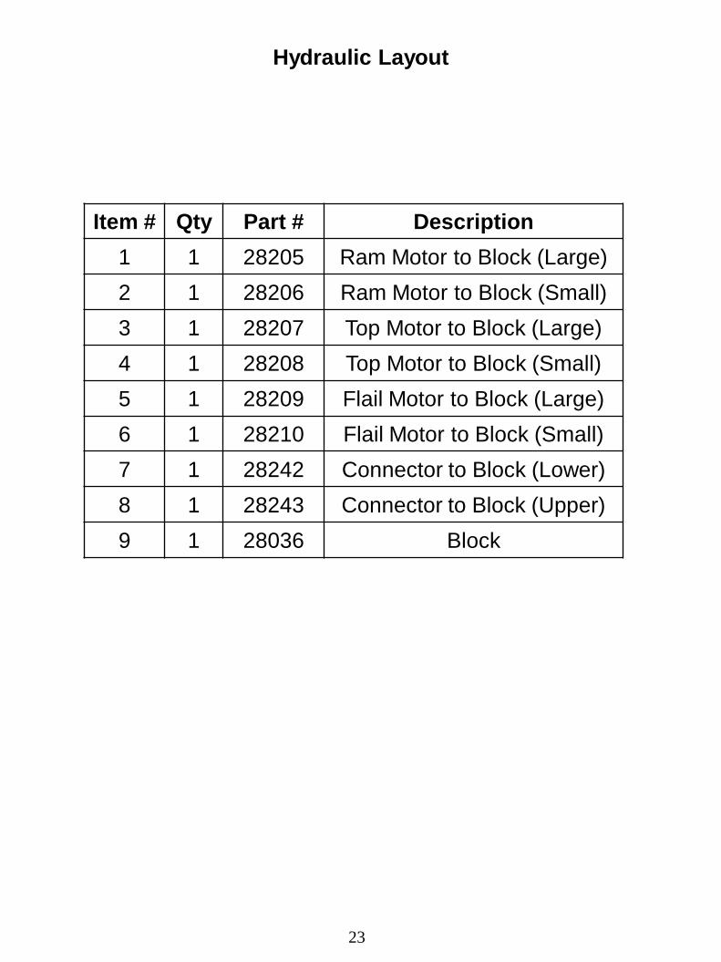
23
Item # Qty Part # Description
1 1 28205 Ram Motor to Block (Large)
2 1 28206 Ram Motor to Block (Small)
3 1 28207 Top Motor to Block (Large)
4 1 28208 Top Motor to Block (Small)
5 1 28209 Flail Motor to Block (Large)
6 1 28210 Flail Motor to Block (Small)
7 1 28242 Connector to Block (Lower)
8 1 28243 Connector to Block (Upper)
9 1 28036 Block
Hydraulic Layout
24
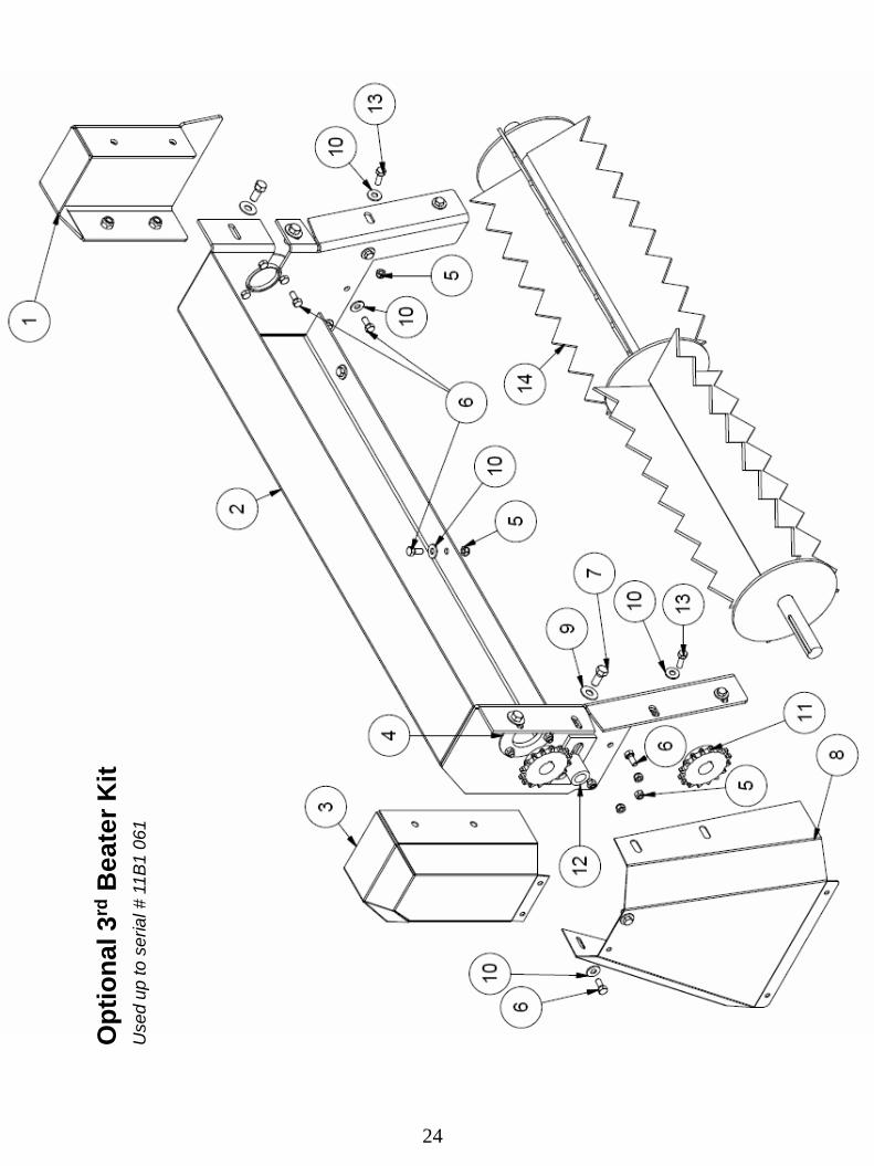
Op
tio
na
l 3
rd B
ea
ter
Kit
U
sed
up
to
se
ria
l #
11
B1
06
1

25
Optional 3rd Beater Kit
Used up to serial # 11B1061
Item Qty Part # Description
1 1 26002 Front Shield
2 1 26000 3rd Beater Main Guard
3 1 26001 3rd Beater Chain Guard
4 2 BEA PF205 3 Hole Flange
5 19 Obtain Locally LN 5/8” Lock Nut
6 17 Obtain Locally HB 5/16 x 3/4 Hex Bolt
7 6 Obtain Locally HB 7/16 x 1 Hex Bolt
8 1 25786 Middle Guard
9 6 Obtain Locally FW 7/16 Flat Washer
10 15 Obtain Locally FW 5/16 Flat Washer
11 2 SPR50B16F-1 Sprocket
12 1 27005 Top Beater Idler Shaft
13 4 Obtain Locally HB 5/16 x 1 Hex Bolt
14 1 27209 Top Beater
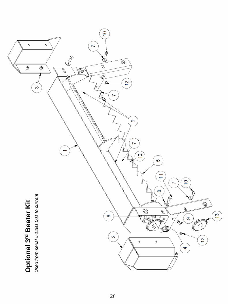
Op
tio
na
l 3
rd B
ea
ter
Kit
U
sed
fro
m s
eria
l #
12
B1
00
1 to
cu
rre
nt
26

Optional 3rd Beater Kit
Used from serial # 12B1 001 to current
Item Qty Part # Description
1 1 26000 Third Beater Main Guard
2 1 26001 Third Beater Main Guard
3 1 26002 Front Shield
4 1 27005 Top Beater Idler Shaft
5 1 27209 Top Beater
6 2 BEA PF205 Bearing
7 13 FW 5/16 Flat Washer
8 6 FW 7/16 Flat Washer
9 15 HB 5/16 X 3/4 Hex Bolt
10 4 HB 5/16 X 1 Hex Bolt
11 6 HB 7/16 X 1 Hex Bolt
12 19 LN 5/16 Lock Nut
13 2 SPR50B16F-1 16 Tooth Sprocket
27

28

29

30

31
