tuned current-output fluxgate
TRANSCRIPT

Ž .Sensors and Actuators 82 2000 161–166www.elsevier.nlrlocatersna
Tuned current-output fluxgate
Pavel Ripka a,), Fritz Primdahl b,1
a Czech Technical UniÕersity, Faculty of Electrical Engineering, Department of Measurement, Technicka 2, 166 27 Prague 6, Czech Republicb Danish Technical UniÕersity, Department of Automation, DK-2800 Lyngby, Denmark
Received 7 June 1999; received in revised form 27 October 1999; accepted 1 November 1999
Abstract
The current-output fluxgate may be tuned by using a serial capacitor. Such tuning increases the sensor sensitivity in the situation whenthe pick-up coil has a low number of turns. We achieved a signalrfeedthrough ratio improvement by a factor of 5. The measuredparameters fit the simplified theoretical model within 20% deviation. q 2000 Elsevier Science S.A. All rights reserved.
Keywords: Magnetic sensors; Magnetometer; Fluxgate
1. Introduction
Fluxgate sensors serve for the measurement of DC andlow-frequency AC magnetic fields. Their principle is basedon modulation of the flux in the pick-up coil by changingthe permeability of the ferromagnetic core by means of the
w xAC excitation field 1 . In order to erase all the remanentmagnetization of the sensor core and thus suppress mem-ory effects, the core should be deeply saturated. Highnarrow peaks of the excitation current may be achieved byusing a tuning capacitor either parallel to the excitation
Ž .winding for higher source resistance or connected seri-Ž .ally for voltage-mode excitation .
Traditional fluxgates use the second harmonic compo-nent of the voltage induced in the pick-up coil. Largespurious components at odd harmonics coming from thetransformer effect were suppressed by using symmetrical
Žconstruction of the sensor two open cores excited in.opposite directions, ring-core, or race track . The voltage-
mode sensor sensitivity may be increased by parametricw xamplification using a parallel tuning capacitor 2,3 . The
theoretical description and numerical results of a capaci-w xtively loaded fluxgate sensor are given in Ref. 4 and in
previous works by Russell et al. More recently, an analyti-cal theory of parallel tuned fluxgate sensors was given by
w xPlayer 5 . If the quality factor of the non-linear tuning
) Corresponding author. Tel.: q42-2-243-53945; fax: q42-2-311-9929.E-mail: [email protected]
1 E-mail: [email protected].
circuit is high, then parametric amplification may evenresult in instability. There are indications that the tuningtechnique concentrates the information from higher-ordereven harmonic components of the induced voltage into thesecond harmonic, which may result in lowering of thesensor noise in case we use the classical synchronous
w xdetector 6 . According to the Serson–Hannaford solutionof the tuning circuit, the only significant contributionscome from the 2nd and 4th harmonics. In some cases, thetuning capacitor is formed by the parasitic capacitance ofthe pick-up coil. This may happen if the number ofwindings is high, the coil is wound without splitting andthe excitation frequency is high. In such a case, the outputvoltage of the unloaded sensor is close to a sine wave. Thismode is usually undesirable as the value of the parasiticcapacitance may be unstable in time and with temperature.The mentioned tuning effect has to be taken into accountin any sensitivity vs. frequency measurements of the flux-gate sensors. Stability of both tuning capacitors is impor-tant; surprisingly, the sensor offset is more sensitive tochanges of the excitation capacitor than to changes of the
w xoutput capacitor C 7 .2Ž .Current-output or short-circuited fluxgates were intro-
w xduced in Ref. 8 . In contrast to the voltage output device,the sensitivity is inversely proportional to the number ofturns of the pick-up coil with certain practical limitationsw x9 . Besides that, the sensitivity also depends on severalgeometrical and material factors. In the ideal case, thepyp value of the output current is directly proportional tothe measured field. In real sensors, the output currentwaveform is distorted by spurious components coming
0924-4247r00r$ - see front matter q 2000 Elsevier Science S.A. All rights reserved.Ž .PII: S0924-4247 99 00332-5

( )P. Ripka, F. PrimdahlrSensors and Actuators 82 2000 161–166162
from the sensor geometrical asymmetry and core non-ho-w xmogeneity 10 . A practical way to detect the difference
between the current value at the time when the excitationis zero and the core permeability is maximum, and thevalue at the instant of fully saturated core when the flux isminimum, is to use the gated integrator. This is in facttime-domain signal processing rather than frequency-do-main, which is more typical for the voltage output device.
In the present paper, we will show that the current-out-put fluxgate may be tuned by using a serial capacitor.
2. Theory
The circuit diagram is shown in Fig. 1. The sensor coreis excited by a periodical current i into saturation. Theex
sensor measures the magnetic field component B in theex
direction of the pick-up coil axis. The pick-up coil isshort-circuited by the current-to-voltage converter with thefeedback resistor R. The capacitor C is used to preventany DC input current of the op amp from flowing throughthe pick-up coil. In the traditional broadband case C ishigh; here, we propose to use C for tuning.
The secondary pick-up coil has a time-changing induc-tion given by
N 2
L t sm Am t 1Ž . Ž . Ž .0 al
where l is the effective length of the coil, A is its crossŽ .sectional area, N is the number of turns, m t is thea
Ž .modulated apparent permeability of the sensor core.The effective length of the coil is here defined as lsm0
NIrB , where B is an external field which is cancelledex ex
by a DC compensation current I into the pick-up coil. Wesuppose that l is only dependent on the coil geometry, noton the sensor core properties nor on the mode of theexcitation. The value of l is higher than the physicallength of the coil and may also be determined from the
Žinductance of the pick-up coil with removed or com-. w xpletely saturated core 11 .
The apparent permeability m is defined as m sa a
m BrB , where B is the magnetic field inside the core.0 ex
Fig. 1. Short-circuited fluxgate input stage. The operational amplifierinverting input acts as a virtual ground, and the sensor secondary currentflows through the feedback resistor R. The capacitor C is used for tuningthe secondary pick-up coil, or for C™`, it acts as a short-circuit in therelevant frequency band.
Apparent permeability is lower than the core materialw xpermeability because of the core demagnetisation 11 . It is
dependent not only on the core size and properties andmode of excitation, but also on the geometry of thepick-up coil.
In order to easily incorporate the measured DC fieldB into the circuit equations, we replace its effect by theex
equivalent coil current i , which flowing in the coilex
would create a field equal to the external field componentalong the coil axis. This ‘‘external field’’ current is relatedto the field by
NB sm i 2Ž .ex 0 ex .l
The total flux in the coil is then
Fs i q i t L t 3Ž . Ž . Ž .ex
and the equation for the input circuit in Fig. 1 becomes:
dF 1q i t r q i t d ts0 4Ž . Ž . Ž .HCud t C
and by inserting F and differentiating with respect to time,we have:
d L t d 1Ž .i q i t L t q i t r q i t d ts0.Ž . Ž . Ž . Ž .Hex Cud t d t C
5Ž .
Ž . Ž .Here, L t is a periodic function of period Ts2pr 2v ,Ž .half the fluxgate core excitation period, and L t may be
approximated by a Fourier’s series:
`
L t sL q L cos nv t n even . 6Ž . Ž . Ž . Ž .Ýo nns2
The zero point for the time is selected to give only cosineterms in the series.
Ž .The current i t similarly contains the fundamentalfrequency 2v and the higher even harmonics, and it is alsorepresented by a Fourier’s series
`
i t s i n cos nv t q i n sin nv t . 7Ž . Ž . Ž . Ž . Ž . Ž .Ž .Ý a bns2
Ž . Ž .The task is now to find i t when L t , the circuitparameters and B are known.ex
Ž . Ž . Ž .The product i t PL t complicates the solution for i t ,X th Ž .because the p harmonic of i t contains contributions
from, in principle, an infinite number of harmonics ofŽ . Ž .L t , and consequently, an exact calculation of i t very
quickly becomes intractable.Two approximations are then made: First, the untuned
broadband sensor secondary case where C™`, and sec-ondly, the Serson–Hannaford approximation for the tuned
w xsecondary case 2 , where the current contains only onefrequency component.

( )P. Ripka, F. PrimdahlrSensors and Actuators 82 2000 161–166 163
2.1. The broadband case
In the broadband case, we have:
dFrd tq i t r s0. 8Ž . Ž .Cu
If the coil losses are small, then the copper resistance rCuw xmay be neglected, as discussed in Ref. 8 . The equation is
then integrated to give:
Fs i q i t L t sconstant, orŽ . Ž .Ž .ex
i t syi qFrL t . 9Ž . Ž . Ž .ex
The output current has no DC component, so by taking theŽ ² :.time-average marked by we get:
² :0syi qF 1rL t ´Fs i L ; 10Ž . Ž .ex ex G 0
where L is the geometric mean value of the pick-up coilG0
induction
² :1rL s 1rL t . 11Ž . Ž .G 0
Notice that L differs from the arithmetic mean valueG0² Ž .: Ž .L s L t from Eq. 6 . And from this we have the basic0
short-circuited fluxgate equation:
LG 0i t s i y1 . 12Ž . Ž .ex L tŽ .The pyp value of the output current was derived in Ref.w x9 :
L LG 0 maxi s i y1 . 13Ž .pyp ex ž /L Lmax min
The complete solution then follows from a Fourier’s analy-Ž Ž . .sis of L rL t y1 .G0
2.2. The tuned secondary case
The sensor secondary circuit may be parallel or seriestuned to one of the even higher harmonics of the excitationfrequency. This enhances the chosen harmonic signal andattenuates all other signals, in particular the omnipresentodd harmonics, which in some cases may be cumbersome.The parallel tuning was first described by Serson and
w x w xHannaford 2 and it is further discussed in Ref. 3 . Seriestuning of the sensor secondary appears not to have beenconsidered elsewhere, and it is briefly discussed theoreti-cally in the following.
Ž .In the second harmonic tuned case, the solution to i tis limited to the Serson–Hannaford approximation:
i t ( i cos 2v t q i sin 2v t 14Ž . Ž . Ž . Ž .a b
because in the tuned circuit, the second harmonic is by farthe dominant signal for any reasonable circuit Q-factor. Inprinciple, the circuit could be tuned to any other evenharmonic frequency to the same effect.
Ž .The assumption of only second harmonic content in i tdramatically limits the number of harmonic components ofŽ . Ž . Ž .L t entering the calculation, because the product i t PL t
has a limited number of terms contributing to the secondŽ .harmonic, even if L t is an infinite Fourier’s series. The
terms needed in this case are:
L t (L qL cos 2v t qL cos 4v t . 15Ž . Ž . Ž . Ž .o 2 4
Ž . Ž . Ž . Ž .We substitute for i t and L t from Eqs. 14 and 15Ž .into Eq. 5 :
di q i cos 2v t q i sin 2v t L qL cos 2v tŽ . Ž . Ž .Ž . Žex a b o 2d t
qL cos 4v t qr i cos 2v t q i sin 2v tŽ . Ž . Ž .. Ž .4 Cu a b
1q i cos 2v t q i sin 2v t d ts0. 16Ž . Ž . Ž .Ž .H a bC
Retaining only the terms leading to second harmonics, weget:
di L cos 2v t qL i cos 2v t q i sin 2v tŽ . Ž . Ž .Ž .ex 2 o a bd t
q i cos 2v t q i sin 2v t L cos 4v tŽ . Ž . Ž .Ž .a b 4
qr i cos 2v t q i sin 2v tŽ . Ž .Ž .Cu a b
1q i sin 2v t y i cos 2v t s0 17Ž . Ž . Ž .Ž .a b2vC
applying the trigonometric product formulas:
di L cos 2v t q i L cos 2v t q i L sin 2v tŽ . Ž . Ž .ex 2 a o b od t
1 1q i L cos 2v t y i L sin 2v tŽ . Ž .a 4 b 42 2
qi r cos 2v t q i r sin 2v tŽ . Ž .a Cu b Cu
i ia bq sin 2v t y cos 2v t s0 18Ž . Ž . Ž .
2vC 2vC
and performing the differentiation:
y2v i L sin 2v t y2v i L sin 2v tŽ . Ž .ex 2 a o
q2v i L cos 2v t yv i L sin 2v tŽ . Ž .b o a 4
yv i L cos 2v t q i r cos 2v tŽ . Ž .b 4 a Cu
iaq i r sin 2v t q sin 2v tŽ . Ž .b Cu 2vC
iby cos 2v t s0 19Ž . Ž .
2vC
then, we divide through by 2v L and assume 2nd har-o
monic resonance:
1Cs 20Ž .22v LŽ . o .
By considering the sine and cosine terms separately, weget the following matrix equation determining i and i :a b
r yLCu 40
2v L 2 L io o a L2s . 21Ž .iyL r i ex4 Cu b Lo2 L 2v Lo o

( )P. Ripka, F. PrimdahlrSensors and Actuators 82 2000 161–166164
The determinant is:2Ds r r2v L y L r2 L s0 for r sv LŽ . Ž .Cu o 4 o Cu 4.
For r -v L , i.e., for sufficiently small losses, the cir-Cu 4w xcuit becomes unstable as shown in Ref. 3 .
3. Measurements
We performed our measurements on the standard ring-w xcore fluxgate sensor similar to that described in Ref. 12 .
The sensor core is made of 18r22 mm rings etched from79Ni4Mn permalloy: 8 rings 50 mm thick form the corewith cross-section of A s0.8 mm2. The rings are stackedFe
in the corundum ceramic holder. The sensor is excited by 4kHz, 5 V rms sinewave from 50 V source. The excitationwinding of N s150 turns, f 0.3 mm is tightly wound on1
the ceramic core holder so it has the toroidal shape.Excitation winding is parallel tuned by C s2.2 nF in1
order to increase the excitation field amplitude. The excita-tion winding resistance was R s0.7 V, its cross-section1
is A s16.2 mm2. The pick-up coil has N s100 turnsair 2
of f 0.3 mm wire wound on glass-fiber bobbin. The coilhas no split; its DC resistance is R s1.8 V, average2
cross-section is A s196.3 mm2 and the coil length ispick
ls22 mm. The core holder with excitation winding ismounted in the middle of the pick-up coil bobbin. Thepick-up coil was connected to the current-to-voltage con-verter with LT 1028 op amp, the feedback resistor valuewas R s5.1 kV.f
Our measurements were made using 1:10 voltage probein order to fit the input range of the SR 830 lock-inamplifier. All the measurements were performed withoutfeedback. The field sensitivity was measured at 1 and 5 mTfor both untuned sensor and sensor tuned to 2nd harmonicby serial capacitor of C s1.7 mF. The measured sensitiv-2
ities for the first six even harmonics are shown in Table 1.Serial tuning increased the sensitivity at 2nd harmonic bythe factor of 5, which is lower than the amplification factorachievable at voltage-output fluxgates. The signal at highereven harmonics is amplified approximately by the factor of2, while in properly tuned voltage-mode sensors, the sensi-tivity at higher harmonics is decreased.
Fig. 2 shows both the tuned and untuned current-outputsensor for the measured field of 2 mT. Top trace is the
Table 1Field sensitivity of untuned and tuned sensor at first six even harmonicsŽ .in mV, 1 mV corresponds to 2 mA
Harmonics
2 4 6 8 10 12
Untuned 1 mT 9.1 6.7 2.6 4.2 0.6 1.15 mT 43.4 38 30.5 22 13.5 6
Tuned 1 mT 47 11 7.3 7 3.5 2.35 mT 219 69 50 36 25 15
Ž . Ž . ŽFig. 2. a,b Excitation current upper trace and output current lower. Ž . Ž .trace, 200 mArdiv. of untuned a and tuned b fluxgate sensor. The
measured field was 2 mT.
excitation current and bottom trace is the output currentŽ .measured at the output of the IrU converter .
4. Calculated values
With the ring-core completely magnetically saturated,the induction of the secondary pick-up coil is measured to
Ž . Žbe L (L s0.1085 mH 0.1080 mH at 1 kHz 10air sat.kHz , and the maximum inductance for unsaturated core is
Ž . Ž .L s0.2465 mH 0.2461 mH at 1 kHz 10 kHz . Let usmaxŽ .approximate the L t waveform by a step function chang-
w xing from L to L 9 as shown in Fig. 3. The fractionmax air
of time spent in saturation by the core is estimated fromthe excitation currentroutput current traces shown in Fig.1a,b to be ds0.0686. The average induction L is calcu-o
Ž .lated from Eq. 8 as
L s0.22678 mH.o
4.1. Broadband output current
The current equivalent to the external field is
i sB lr m N s9.151 mAŽ .ex ex o
Ž .for 50,000 nT external field along the sensor axis Fig. 4 .
( )P. Ripka, F. PrimdahlrSensors and Actuators 82 2000 161–166 165
Fig. 3. The time variation of the fluxgate secondary pick-up coil induc-tance for two periods of the excitation frequency. During the times whenthe core is in magnetic saturation then the secondary inductance decreasesto approximately the air-cored coil value. The average induction deter-mining the resonance is L .o
An effective coil winding length ls23 mm is adoptedin order to match the calculated value to the measured
w xsecondary coil induction 3 .The waveform of the theoretical output current is also
w xsquarewave with a duty factor of d 9 . The Fourier’sanalysis of a periodically repeated narrow square impulseof width dPT , period T and amplitude I yields thecoefficients:
i n s2 Ir nPp sin nPpPd cosine termsŽ . Ž . Ž .a
i n s0 sine terms.Ž .b
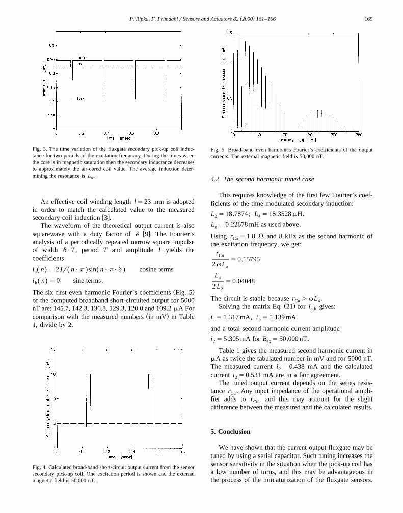
Ž .The six first even harmonic Fourier’s coefficients Fig. 5of the computed broadband short-circuited output for 5000nT are: 145.7, 142.3, 136.8, 129.3, 120.0 and 109.2 mA.For
Ž .comparison with the measured numbers in mV in Table1, divide by 2.
Fig. 4. Calculated broad-band short-circuit output current from the sensorsecondary pick-up coil. One excitation period is shown and the externalmagnetic field is 50,000 nT.
Fig. 5. Broad-band even harmonics Fourier’s coefficients of the outputcurrents. The external magnetic field is 50,000 nT.
4.2. The second harmonic tuned case
This requires knowledge of the first few Fourier’s coef-ficients of the time-modulated secondary induction:
L s18.7874; L s18.3528 mH.2 4
L s0.22678 mH as used above.o
Using r s1.8 V and 8 kHz as the second harmonic ofCu
the excitation frequency, we get:rCu
s0.157952v Lo
L4s0.04048.
2 L2
The circuit is stable because r )v L .Cu 4Ž .Solving the matrix Eq. 21 for i gives:a,b
i s1.317 mA, i s5.139 mAa b
and a total second harmonic current amplitude
i s5.305 mA for B s50,000 nT.2 ex
Table 1 gives the measured second harmonic current inmA as twice the tabulated number in mV and for 5000 nT.The measured current i s0.438 mA and the calculated2
current i s0.531 mA are in a fair agreement.2
The tuned output current depends on the series resis-tance r . Any input impedance of the operational ampli-Cu
fier adds to r , and this may account for the slightCu
difference between the measured and the calculated results.
5. Conclusion
We have shown that the current-output fluxgate may betuned by using a serial capacitor. Such tuning increases thesensor sensitivity in the situation when the pick-up coil hasa low number of turns, and this may be advantageous inthe process of the miniaturization of the fluxgate sensors.

( )P. Ripka, F. PrimdahlrSensors and Actuators 82 2000 161–166166
We have increased the sensitivity of the ring-core short-circuited fluxgate sensor five times while the level of thespurious feedthrough remained the same. Serial tuning iseasily made only by decreasing the value of the input
Žcapacitor. The change of signal-to-noise ratio or effective.noise in units of the measured field with tuning is under
investigation. The preliminary results are ambiguous: noisew ximprovement with tuning was reported in Ref. 6 , while
w xnoise degradation by tuning was observed in Ref. 3 andw xrecently in Ref. 13 .
References
w x1 P. Ripka, Review of fluxgate sensors, Sensors and Actuators A 33Ž .1992 129–141.
w x2 P.H. Serson, W.L.W. Hannaford, A portable electrical magnetome-Ž .ter, Can. J. Technol. 34 1956 232–243.
w x3 F. Primdahl, P. Anker Jensen, Noise in the tuned fluxgate, J. Phys.Ž .E: Sci. Instrum. 20 1987 637–642.
w x4 Z. Gao, R.D. Russell, Fluxgate sensor theory: sensitivity and phaseŽ .plane analysis, IEEE Trans. Geosci. 25 1987 862–870.
w x5 M.A. Player, Parametric amplification in fluxgate sensors, J.Phys. DŽ .21 1988 1473–1480.
w x6 P. Ripka, W. Billingsley, Fluxgate: tuned vs. untuned output, IEEEŽ .Trans. Magn. 34 1998 1303–1305.
w x Ž .7 A. Tipek, P. Ripka, P. Kaspar, Gradiometric sensor in Czech , Proc.ˇof the Sensory-snimace-aplikace conf., Ostrava, 1998.
w x8 F. Primdahl, J.R. Petersen, C. Olin, K. Harbo Andersen, The short-Ž .circuited fluxgate output current, J. Phys. E: Sci. Instrum. 22 1989
349–353.w x9 F. Primdahl, P. Ripka, J.R. Petersen, O.V. Nielsen, The short-cir-
Ž .cuited fluxgate sensitivity parameters, Meas. Sci. Technol. 2 19911039–1045.
w x10 J.R. Petersen, F. Primdahl, B. Hernando, A. Fernandez, O.V. Nielsen,
The ring core fluxgate sensor null feed-through signal, Meas. Sci.Ž .Technol. 3 1992 1149–1154.
w x11 F. Primdahl, B. Hernando, O.V. Nielsen, J.R. Petersen, Demagnetis-ing factor and noise in the fluxgate ring-core sensor, J. Phys. E: Sci.
Ž .Instrum. 22 1989 1004–1008.w x12 P. Ripka, P. Kaspar, Portable fluxgate magnetometer, Sensors and
Ž .Actuators A 68 1998 286–289.w x13 E.B. Pedersen, Digitalisation of Fluxgate Magnetometer, PhD The-
sis, Academy of Technical Sciences, TERMA Elektronik and De-partment of Automation, Technical University of Denmark, DK-2800Lyngby, Denmark, June 1999.
Biographies
Ž .PaÕel Ripka received an Ing. degree in 1984, a CSc equivalent to PhDin 1989 and a doctoral degree in 1996 at the Czech Technical University,Prague, Czech Republic. He works at the Department of Measurement,Faculty of Electrical Engineering, Czech Technical University as a lec-turer, teaching courses in Electrical Measurements and Instrumentation,Engineering Magnetism and Sensors. His main research interests aremagnetic measurements and magnetic sensors, especially, fluxgate. He isa member of Elektra Society, Czech Metrological Society, Czech Na-tional IMEKO Committee and Eurosensors Steering Committee.
Fritz Primdahl received an MSc in Electrical Engineering and Physics atthe Technical University of Denmark in 1964. He worked as ResearchScientist at the Department of Geophysics, Danish Meteorological Insti-
Ž .tute 1966–1968 and 1970–1980 . In 1968–1970, he was awarded afellowship by the National Research Council of Canada. Since 1980, hehas been with the Danish Space Research Institute, now on leave to leadthe Ørsted satellite science instrumentation team at the Technical Univer-sity of Denmark. He mainly works in space magnetometry and spaceplasma physics. He was a member or head of teams developing instru-
Žmentation for sounding rockets and satellites CLUSTER, Oersted,.ASTRID-2, CHAMP and SAC-C and scientific teams planning the space
experiments and analyzing the data. He is a member of Danish Geophysi-cal Society.