tunnel carwash support components - belanger … system...owners manual tunnel carwash support...
TRANSCRIPT
Owners Manual
Tunnel Carwash Support
Components • 5HP Hydraulic Unit
• 10HP Hydraulic Unit • 20HP Hydraulic Unit • 32 Output Controller • 64 Output Controller • Motor Starter Panel
• Attended Operator Station (1515 Button Box)
• Solution Delivery Module (SDM) • Triple Foam Panel
1MANUL760REV 05
Belanger, Inc.P.O. Box 5470
Northville, MI 48167-5470Customer Service Phone (248) 374-4700
Fax (248) 380-9681www.belangerinc.com

Belanger, Inc. Tunnel Support Components

TUNNEL SUPPORT COMPONENTS
1MANUL760 Belanger, Inc. * 1001 Doheny Ct. * Northville, MI 48167 * Ph (248) 349-7010 * Fax (248) 380-9681 1
Table of Contents
Belanger Incorporated Limited Warranty........................................................ 4
Operational Warning......................................................................................... 5
Important Safety Information ........................................................................... 6
IMPORTANT Safety Information – MUST READ ............................................. 7 Safety Warnings........................................................................................................................... 7
Introduction ....................................................................................................... 8 Basic Overview ............................................................................................................................ 8 Component Placement ................................................................................................................ 8
Installation ......................................................................................................... 9 Utility Trak® (if applicable) ............................................................................................................ 9 DCC Placement ........................................................................................................................... 9 Hydraulic Unit Overview............................................................................................................. 10
Placement ............................................................................................................................................................. 10 Fluid Guidelines..................................................................................................................................................... 11 Flush and Startup procedure (10HP and 20HP) ................................................................................................... 12 Maintenance.......................................................................................................................................................... 12 Startup procedure (5HP) ....................................................................................................................................... 12
5HP Hydraulic Unit..................................................................................................................... 13 Overview ............................................................................................................................................................... 13
5HP Hydraulic Unit Connections ............................................................................................... 13 5HP Hydraulic Unit Manifold...................................................................................................... 14 5HP Hydraulic Unit Replacement Parts..................................................................................... 14 10HP Hydraulic Unit................................................................................................................... 15
Fluid Cap............................................................................................................................................................... 16 Fluid Level Sensor................................................................................................................................................. 16 Main Electrical Feed.............................................................................................................................................. 16 Pressure Adjustment Control and Feed Pressure Gauge..................................................................................... 16 Fluid Feed Manifold............................................................................................................................................... 17 Main Fluid Return Valve ........................................................................................................................................ 17
20HP Hydraulic Unit................................................................................................................... 18 Fluid Cap............................................................................................................................................................... 19 Fluid Level Sensor................................................................................................................................................. 19 Main Electrical Feed.............................................................................................................................................. 19 Pressure Adjustment Manifold and Feed Pressure Gauge ................................................................................... 19 Fluid Feed Manifold............................................................................................................................................... 20 Main Fluid Return Valve ........................................................................................................................................ 20

TUNNEL SUPPORT COMPONENTS
2 Belanger, Inc. * 1001 Doheny Ct. * Northville, MI 48167 * Ph (248) 349-7010 * Fax (248) 380-9681 1MANUL760
Table of Contents Pneumatic Air- Panel Overview ................................................................................................. 21 System Air Panel ....................................................................................................................... 22
Overview ................................................................................................................................................................22 Air Panel Overview.................................................................................................................................................22
Roller-Call Panel (Optional) ....................................................................................................... 23 Air Panel.................................................................................................................................................................23 Air Panel Overview.................................................................................................................................................23 Air Circuit Connections...........................................................................................................................................23 Inspection and Cleaning.........................................................................................................................................24 Wave Full Side Washer®, Part #102060 ................................................................................................................25 Wave Wrap® driver side, Part #102025 .................................................................................................................25 Wave Wrap® passenger side, Part #102026..........................................................................................................25 Separate, identical panels required for the driver side and passenger side. .........................................................25 Gyro Wrap®, Part #102022 ....................................................................................................................................25
32 Output Controller................................................................................................................... 26 Component Identification .......................................................................................................................................26
64 Output Controller................................................................................................................... 27 Component Identification .......................................................................................................................................27
Motor Starter Panel.................................................................................................................... 28 The typical Enduro Class 60 MCC contains the following:.....................................................................................28 The typical Pro Class 100 MCC contains the following:.........................................................................................28
Attended Operator Station (1515 Button Box)........................................................................... 29 Usage.....................................................................................................................................................................29 Schematic ..............................................................................................................................................................30
Solution Delivery Module (SDM) General.................................................................................. 31 Overview ................................................................................................................................................................31 Water manifold .......................................................................................................................................................31 Water Valves..........................................................................................................................................................32 Chemical Pumps ....................................................................................................................................................32 Pump Cover ...........................................................................................................................................................32 Electrical Distribution Block....................................................................................................................................33
Solution Delivery Module (SDM) for Enduro Class 60............................................................... 34 Solution Delivery Module (SDM) #1 for Pro Class 100.............................................................. 35 Solution Delivery Module (SDM) #2 for Pro Class 100.............................................................. 36 Triple Foam Panel...................................................................................................................... 37
3-Way Valve...........................................................................................................................................................38 Chemical Pumps ....................................................................................................................................................38 Pressure Regulator ................................................................................................................................................38 Foam Output Manifold............................................................................................................................................39 Pump Cover ...........................................................................................................................................................39 Electrical Terminal Box ..........................................................................................................................................39
TUNNEL SUPPORT COMPONENTS
1MANUL760 Belanger, Inc. * 1001 Doheny Ct. * Northville, MI 48167 * Ph (248) 349-7010 * Fax (248) 380-9681 3
Table of Contents
Replacement Parts.......................................................................................... 40 DCC-32 and DCC-64 Control Panel .......................................................................................... 40 102798: System Air Panel ......................................................................................................... 41 102955: DuraTrans XD Air Panel .............................................................................................. 42 108006: Classic Air Panel.......................................................................................................... 44 Repair Kits ................................................................................................................................. 45
3rd party Component Maintenance................................................................. 46 Metering Pumps......................................................................................................................... 46
1PUMP700 (Concentrate Pump), 1PUMP725 (Non-Concentrate Pump .............................................................. 46
TUNNEL SUPPORT COMPONENTS
4 Belanger, Inc. * 1001 Doheny Ct. * Northville, MI 48167 * Ph (248) 349-7010 * Fax (248) 380-9681 1MANUL760
Belanger Incorporated Limited Warranty LIMITED WARRANTY: Seller warrants to the original purchaser that the goods sold hereunder, which are fabricated exclusively by Seller, shall be free from defects in workmanship and material under normal use and service for a period of one year from the date of shipment. This warranty is subject to the following limitations: (1) Labor to repair or replace parts is warranted to Purchaser during normal business hours through an authorized distributor or value added reseller (VAR) of Seller, or direct with Seller, for 90 calendar days from date of invoice. Labor warranty excludes all claims for warranty on labor that are determined to be nuisance service calls, misuse, lack of operational training, neglect, improper installation, repair, alteration, act of God, or accident from third party damage. Seller reserves the sole right to make determinations on the above stated limitation. All labor and service provided beyond the expiration of the labor warranty period shall be charged to the Purchaser at the rates established by the local authorized distributor or value added reseller (VAR) or direct with Seller; (2) Defective parts will be repaired or replaced through an authorized distributor or value added reseller (VAR) of Seller, or direct with Seller. This warranty does not apply to damage resulting from accident, misuse, abuse, negligence or normal wear and tear to the depreciable parts. Purchaser agrees to submit to and assist Seller or its authorized distributor or value added reseller (VAR) in conducting in-warranty inspections of the machinery and equipment including inspection of any part claimed to be defective by the Purchaser; (3) This warranty shall be void if the factory specifications for operation and maintenance are not followed, or if other than factory authorized erection, alterations or modifications are made to any parts or equipment; (4) This warranty shall be void for all equipment failures and premature component wear caused by the use of corrosive chemicals in the wash process. The following list includes some, but not all, of the particularly corrosive chemicals that if used in conjunction with Belanger equipment will void the warranty: Hydrofluoric Acid, Ammonium Bi-flouride, Bromic Acid, Muriatic Acid, Sulfonic Acid, Phosphoric Acid, Hydrogen Cyanide, Hydrochloric Acid, Sodium Hydroxide and Chlorinated Solvents. The Purchaser also agrees to accept the responsibility and liability for the selection and use of any chemicals listed above; (5) This warranty shall be void for all equipment failures and premature component wear caused by the use of reclaim water in the wash process; specifically, failure of high pressure valves, high pressure pumps, nozzles and un-loader valves, (6) Seller makes no warranty, express or implied, with respect to the design or operation of any entire system, in which Seller’s goods sold hereunder are mere components. THIS WARRANTY IS EXPRESSLY IN LIEU OF ALL OTHER WARRANTIES, EXPRESS OR IMPLIED, WHETHER STATUTORY OR OTHERWISE, INCLUDING ANY IMPLIED WARRANTY OF MERCHANTABILITY OR FITNESS FOR A PARTICULAR PURPOSE; (7) In no event shall Seller be liable for any incidental, special, consequential or exemplary damages resulting from the furnishing, performance or use of any goods or services sold pursuant hereto, whether due to a breach of contract, breach of warranty, the negligence of Seller or to otherwise; not for loss of business; inconvenience, or property damage of any kind; or for any service not expressly provided herein related to or arising from the equipment or goods sold. This limitation of liability extends to any damages resulting in any way from purchaser’s use of any engineering recommendations, sales representations, technical assistance, advice or data supplied by seller to purchaser in connection with the goods or services supplied, other than that information contained in Belanger manuals, pursuant to this acknowledgment. This limitation of liability additionally extends to any damages of whatever nature resulting in any way from the purchaser’s selection and use of any chemicals not manufactured exclusively by seller but used with the purchased goods. All warranties express, implied, or statutory, pertaining to Seller’s machinery, parts, and equipment are fully set forth herein. This limited warranty applies to the original purchaser only and is not transferable. No addition to or modification of any of the provisions of the above stated Limited Warranty shall be binding upon the Seller, unless made in writing and signed by a duly authorized employee of Seller.
Copyright © 2000 by Belanger, Inc. All rights reserved. No part of this work may be reproduced or transmitted in any form or by any means, electronic or mechanical, including photocopying and recording, or by any information storage or retrieval system, except as may be expressly permitted by the 1976 Copyright Act. Revised as of 6-15-00. Belanger reserves the right to change or modify the Belanger Inc. Limited Warranty without notice.
TUNNEL SUPPORT COMPONENTS
1MANUL760 Belanger, Inc. * 1001 Doheny Ct. * Northville, MI 48167 * Ph (248) 349-7010 * Fax (248) 380-9681 5
Operational Warning Formulations containing the chemicals listed below are particularly dangerous and should not be used even at low concentrations:
• Hydrofluoric Acid
• Ammonium Bi-flouride
• Bromic Acid
• Muriatic Acid
• Sulfonic Acid
• Phosphoric Acid
• Hydrogen Cyanide
• Hydrochloric Acid
• Chlorinated Solvents Belanger, Inc., does not endorse or condone the use of chemicals that are potentially dangerous to human health, the environment or property. Belanger recognizes that it is the right and sole decision of the end user operators of our equipment as to the type and dilution ratio of the chemicals used in their facilities. We strongly recommend that the end user does not select products containing any of the chemicals listed above as an ingredient in the wash solutions. The chemicals listed above are potentially dangerous to human health, and have a detrimental, deteriorating effect on the equipment and the facility. Be advised that a portion of, or all of your warranty will be voided if you determine to use any of the chemicals listed above as an ingredient in the wash solutions in conjunction with your Belanger automatic car wash equipment:
Limitation (4), of Paragraph (8), Limited Warranty, of the Belanger Terms and Conditions of Sales describes the potential limitation of warranty due to your chemical selection:
(4) This warranty shall be void for all equipment failures and premature component wear caused by the use of corrosive chemicals in the wash process. The following list includes some, but not all, of the particularly corrosive chemicals that if used in conjunction with Belanger equipment will void the warranty: Hydrofluoric Acid, Ammonium Bi-flouride, Bromic Acid, Muriatic Acid, Sulfonic Acid, Phosphoric Acid, Hydrogen Cyanide, Hydrochloric Acid, and Chlorinated Solvents. The Purchaser also agrees to accept the responsibility and liability for the selection and use of any chemicals listed above;
However, should the end user decide to use formulations containing any of the above ingredients, the end user should institute a comprehensive training program and implement detailed operational parameters within their organization for the proper handling and treatment of such products to minimize the potential dangers involved. Consult your chemical supplier for assistance in establishing operational guidelines in the use of their products. MSDS (Material Safety Data Sheet) should be obtained from the chemical supplier before using any chemical formulation.
CAUTION During the installation process the installer is responsible for re-tightening ALL lugs, set screws and terminals located in the electrical panels. Components may
vibrate loose during shipping.
TUNNEL SUPPORT COMPONENTS
6 Belanger, Inc. * 1001 Doheny Ct. * Northville, MI 48167 * Ph (248) 349-7010 * Fax (248) 380-9681 1MANUL760
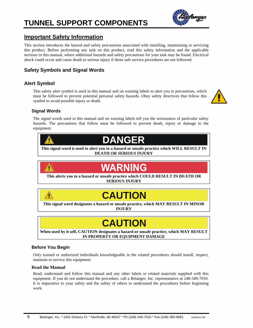
Important Safety Information This section introduces the hazard and safety precautions associated with installing, maintaining or servicing this product. Before performing any task on this product, read this safety information and the applicable sections in this manual, where additional hazards and safety precautions for your task may be found. Electrical shock could occur and cause death or serious injury if these safe service procedures are not followed.
Safety Symbols and Signal Words
Alert Symbol This safety alert symbol is used in this manual and on warning labels to alert you to precautions, which must be followed to prevent potential personal safety hazards. Obey safety directives that follow this symbol to avoid possible injury or death.
Signal Words The signal words used in this manual and on warning labels tell you the seriousness of particular safety hazards. The precautions that follow must be followed to prevent death, injury or damage to the equipment.
DANGER This signal word is used to alert you to a hazard or unsafe practice which WILL RESULT IN
DEATH OR SERIOUS INJURY
This alerts you to a hazard or unsafe practice which COULD RESULT IN DEATH OR SERIOUS INJURY
CAUTIONThis signal word designates a hazard or unsafe practice, which MAY RESULT IN MINOR
INJURY
CAUTIONWhen used by it self, CAUTION designates a hazard or unsafe practice, which MAY RESULT
IN PROPERTY OR EQUIPMENT DAMAGE
Before You Begin Only trained or authorized individuals knowledgeable in the related procedures should install, inspect, maintain or service this equipment.
Read the Manual Read, understand and follow this manual and any other labels or related materials supplied with this equipment. If you do not understand the procedure, call a Belanger, Inc. representative at 248-349-7010. It is imperative to your safety and the safety of others to understand the procedures before beginning work.
TUNNEL SUPPORT COMPONENTS
1MANUL760 Belanger, Inc. * 1001 Doheny Ct. * Northville, MI 48167 * Ph (248) 349-7010 * Fax (248) 380-9681 7
IMPORTANT Safety Information – MUST READ
Safety Warnings
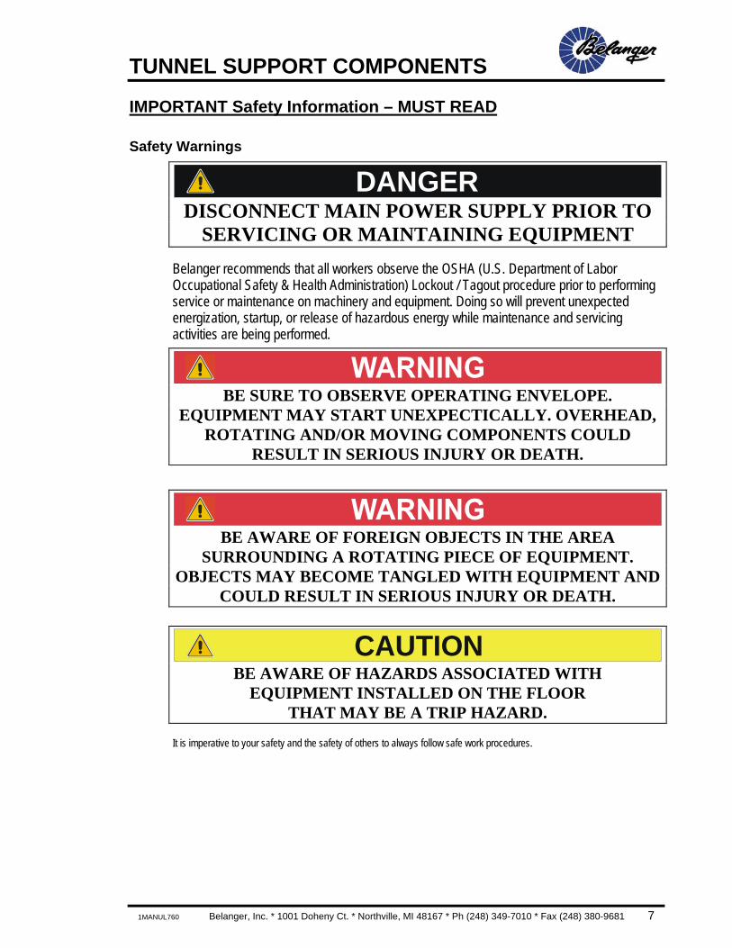
DANGER DISCONNECT MAIN POWER SUPPLY PRIOR TO
SERVICING OR MAINTAINING EQUIPMENT
Belanger recommends that all workers observe the OSHA (U.S. Department of Labor Occupational Safety & Health Administration) Lockout / Tagout procedure prior to performing service or maintenance on machinery and equipment. Doing so will prevent unexpected energization, startup, or release of hazardous energy while maintenance and servicing activities are being performed.
BE SURE TO OBSERVE OPERATING ENVELOPE. EQUIPMENT MAY START UNEXPECTICALLY. OVERHEAD,
ROTATING AND/OR MOVING COMPONENTS COULD RESULT IN SERIOUS INJURY OR DEATH.
BE AWARE OF FOREIGN OBJECTS IN THE AREA SURROUNDING A ROTATING PIECE OF EQUIPMENT.
OBJECTS MAY BECOME TANGLED WITH EQUIPMENT AND COULD RESULT IN SERIOUS INJURY OR DEATH.
CAUTIONBE AWARE OF HAZARDS ASSOCIATED WITH
EQUIPMENT INSTALLED ON THE FLOOR THAT MAY BE A TRIP HAZARD.
It is imperative to your safety and the safety of others to always follow safe work procedures.
TUNNEL SUPPORT COMPONENTS
8 Belanger, Inc. * 1001 Doheny Ct. * Northville, MI 48167 * Ph (248) 349-7010 * Fax (248) 380-9681 1MANUL760
Introduction
Basic Overview The components covered in this manual are typically the most critical parts of the Belanger, Inc. Car Wash System, it is imperative that you understand the concepts used in their designs and they MUST be installed correctly.
Component Placement
Note: See site-specific prints and drawings for dimensions and actual tunnel placement of all components.
Traditionally it is advised to locate and install the Motor Starter Panel and the Output Controller first so that the utility contractors can get their work out of the way.
The Motor Starter Panel and the Output Controller are the “BRAINS” of the system. They do the thinking. They house the following components:
• Motor Starters • Main Disconnect • System Output Boards The Hydraulic Unit and Pneumatic Panels are the “HEART” of the system. They pump life into the tunnel components. The Pneumatic Panels should be mounted on the wall very close by.
All of the above components are designed to be installed in a traditional “Back Room” and comes with a standard utility package that will accommodate most back rooms. Your VAR can acquire any additionally required utility materials.
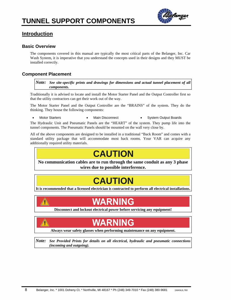
CAUTION No communication cables are to run through the same conduit as any 3 phase
wires due to possible interference.
CAUTIONIt is recommended that a licensed electrician is contracted to perform all electrical installations.
Disconnect and lockout electrical power before servicing any equipment!
Always wear safety glasses when performing maintenance on any equipment.
Note: See Provided Prints for details on all electrical, hydraulic and pneumatic connections (incoming and outgoing).

TUNNEL SUPPORT COMPONENTS
1MANUL760 Belanger, Inc. * 1001 Doheny Ct. * Northville, MI 48167 * Ph (248) 349-7010 * Fax (248) 380-9681 9
Installation
Utility Trak® (if applicable) If you have purchased the optional Utility Trak System, the water, air and hydraulic utility lines going from the Back Room to the components are to be run through and over the utility track. See the Utility Trak System manual for more details.
DCC Placement
NOTE: REFER TO SITE DRAWINGS AND ELECTRICAL SCHEMATICS FOR SPECIFIC WIRE CONNECTIONS.
• The Motor Starter Panel is equipped with a load specific, non-fusible disconnect. The disconnect requires proper size copper wire (DO NOT USE ALUMINUM WIRE), an upstream current limiting device sized in accordance with the systems FLA and an electrical grounding conductor.
• The DCC requires two 110VAC to 120VAC – 20AMP dedicated circuits. The hot wire MUST be yellow, #12 AWG, stranded wire to match the systems labeling.
• The electrical contractor should provide and install the junction boxes, etc., in order to wire 110VAC-120VAC power (hot, neutral and ground) from the DCC to all of the Solution Delivery Module(s) (SDM), auxiliary motor starters (if applicable) and the Air Cannon Dryer Control Panel (if applicable).
• The electrical contractor is to supply all materials necessary to wire system inputs. Refer to site-specific system layouts and/or schematics for location of each input.
• EMERGENCY STOPS (E-STOPS) ARE HIGHLY RECOMMENDED throughout the carwash tunnel and wherever employees are present. The electrical contractor is to wire E-Stop circuits to all appropriate locations. If you are not sure where E-Stops should be posted, contact your VAR. Be sure to use the appropriate enclosure and activation button(s) for areas of installation.
• E-Stop Push buttons MUST be a two position, maintained, push/pull type switch assembly. They are also to be wired as “Normally Closed” (N/C).
CAUTION No communication cables are to run through the same conduit as any 3-phase
wires due to possible interference.

TUNNEL SUPPORT COMPONENTS
10 Belanger, Inc. * 1001 Doheny Ct. * Northville, MI 48167 * Ph (248) 349-7010 * Fax (248) 380-9681 1MANUL760
Installation
Hydraulic Unit Overview The Hydraulic Supply Units come with a premium Variable Volume Pumps. When adjusting the speed of a piece of equipment, the speed of other components will not be affected unless the maximum supply capabilities are exceeded. The pump throttles itself to only displace the required amount of oil.
CAUTION This unit should NEVER be used to run only a Conveyor. This will cause overheating and
damage the unit.
There are three available Hydraulic Supply Units, the 5HP unit, 10HP unit and the 20HP unit. The number of components determines the size required in the system and/or the specifics of those components.
The 5HP Hydraulic Unit is a fixed displacement and should be purchased when extra capacity is required. The Enduro Class 60 comes standard with a 10HP Unit and the Pro Class100 comes with a 20HP unit.
It may become necessary to upgrade your system from a 10HP to a 20HP hydraulic unit or add an auxiliary hydraulic unit if you add components to your system at a later date. If you have questions about your systems hydraulic capacity, consult your local VAR.
Of the two variable displacement units there are some distinct differences. The 20HP unit has larger feed and return manifolds.
CAUTION Do Not exceed 1000 PSI operating pressure on ANY systems Hydraulic Unit. Failure to stay
within limits will trip the Motor Starters.
Placement Place your Hydraulic Unit in the desired location and bolt it to the floor. Be sure it is in a safe and dry environment.
TUNNEL SUPPORT COMPONENTS
1MANUL760 Belanger, Inc. * 1001 Doheny Ct. * Northville, MI 48167 * Ph (248) 349-7010 * Fax (248) 380-9681 11
Installation
Hydraulic Unit Overview
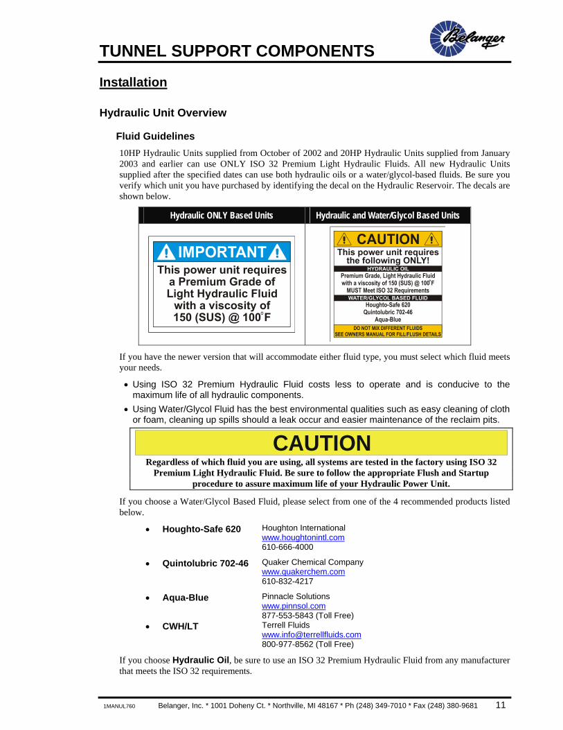
Fluid Guidelines 10HP Hydraulic Units supplied from October of 2002 and 20HP Hydraulic Units supplied from January 2003 and earlier can use ONLY ISO 32 Premium Light Hydraulic Fluids. All new Hydraulic Units supplied after the specified dates can use both hydraulic oils or a water/glycol-based fluids. Be sure you verify which unit you have purchased by identifying the decal on the Hydraulic Reservoir. The decals are shown below.
Hydraulic ONLY Based Units Hydraulic and Water/Glycol Based Units
If you have the newer version that will accommodate either fluid type, you must select which fluid meets your needs.
• Using ISO 32 Premium Hydraulic Fluid costs less to operate and is conducive to the maximum life of all hydraulic components.
• Using Water/Glycol Fluid has the best environmental qualities such as easy cleaning of cloth or foam, cleaning up spills should a leak occur and easier maintenance of the reclaim pits.
CAUTION Regardless of which fluid you are using, all systems are tested in the factory using ISO 32
Premium Light Hydraulic Fluid. Be sure to follow the appropriate Flush and Startup procedure to assure maximum life of your Hydraulic Power Unit.
If you choose a Water/Glycol Based Fluid, please select from one of the 4 recommended products listed below.
• Houghto-Safe 620 Houghton International www.houghtonintl.com 610-666-4000
• Quintolubric 702-46 Quaker Chemical Company www.quakerchem.com 610-832-4217
• Aqua-Blue Pinnacle Solutions www.pinnsol.com 877-553-5843 (Toll Free)
• CWH/LT Terrell Fluids [email protected] 800-977-8562 (Toll Free)
If you choose Hydraulic Oil, be sure to use an ISO 32 Premium Hydraulic Fluid from any manufacturer that meets the ISO 32 requirements.
TUNNEL SUPPORT COMPONENTS
12 Belanger, Inc. * 1001 Doheny Ct. * Northville, MI 48167 * Ph (248) 349-7010 * Fax (248) 380-9681 1MANUL760
Installation
Hydraulic Unit Overview
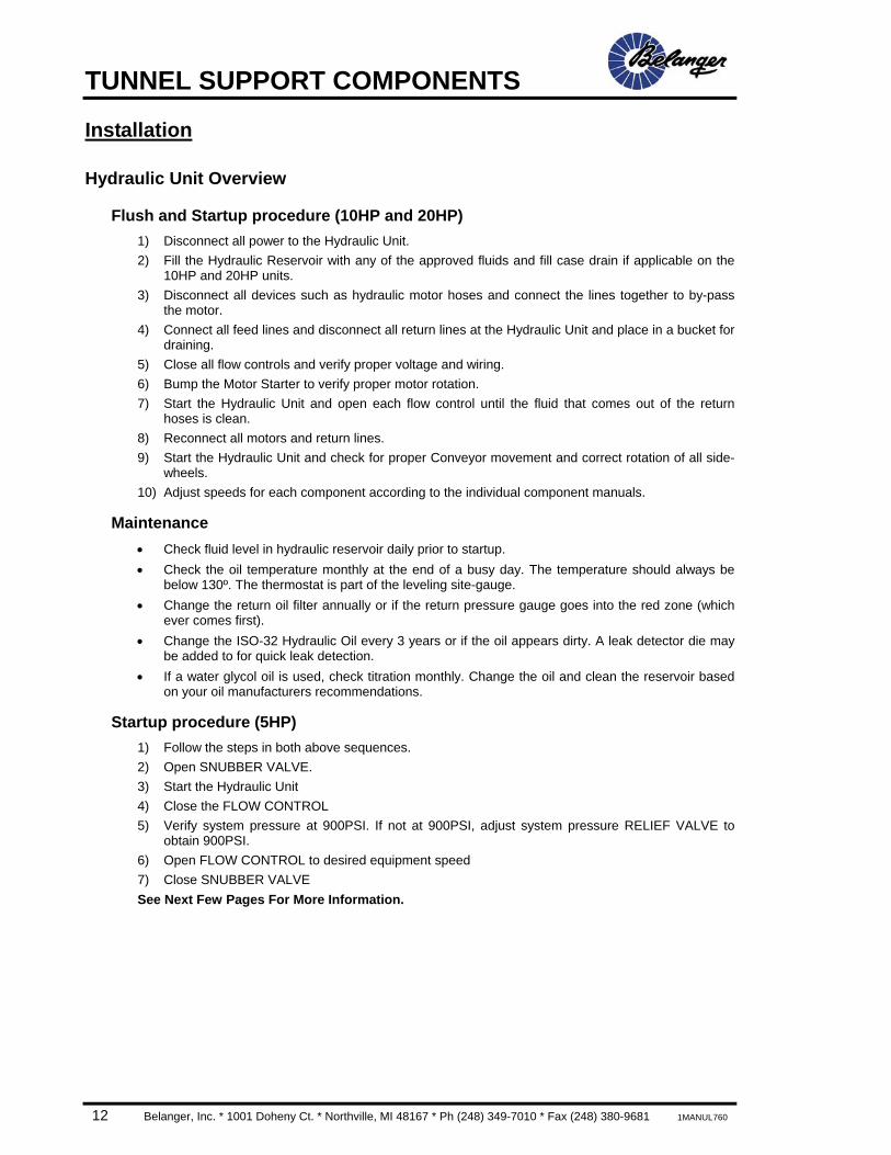
Flush and Startup procedure (10HP and 20HP) 1) Disconnect all power to the Hydraulic Unit. 2) Fill the Hydraulic Reservoir with any of the approved fluids and fill case drain if applicable on the
10HP and 20HP units. 3) Disconnect all devices such as hydraulic motor hoses and connect the lines together to by-pass
the motor. 4) Connect all feed lines and disconnect all return lines at the Hydraulic Unit and place in a bucket for
draining. 5) Close all flow controls and verify proper voltage and wiring. 6) Bump the Motor Starter to verify proper motor rotation. 7) Start the Hydraulic Unit and open each flow control until the fluid that comes out of the return
hoses is clean. 8) Reconnect all motors and return lines. 9) Start the Hydraulic Unit and check for proper Conveyor movement and correct rotation of all side-
wheels. 10) Adjust speeds for each component according to the individual component manuals.
Maintenance • Check fluid level in hydraulic reservoir daily prior to startup. • Check the oil temperature monthly at the end of a busy day. The temperature should always be
below 130º. The thermostat is part of the leveling site-gauge. • Change the return oil filter annually or if the return pressure gauge goes into the red zone (which
ever comes first). • Change the ISO-32 Hydraulic Oil every 3 years or if the oil appears dirty. A leak detector die may
be added to for quick leak detection. • If a water glycol oil is used, check titration monthly. Change the oil and clean the reservoir based
on your oil manufacturers recommendations.
Startup procedure (5HP) 1) Follow the steps in both above sequences. 2) Open SNUBBER VALVE. 3) Start the Hydraulic Unit 4) Close the FLOW CONTROL 5) Verify system pressure at 900PSI. If not at 900PSI, adjust system pressure RELIEF VALVE to
obtain 900PSI. 6) Open FLOW CONTROL to desired equipment speed 7) Close SNUBBER VALVE See Next Few Pages For More Information.
TUNNEL SUPPORT COMPONENTS
1MANUL760 Belanger, Inc. * 1001 Doheny Ct. * Northville, MI 48167 * Ph (248) 349-7010 * Fax (248) 380-9681 13
Installation
5HP Hydraulic Unit Dimensions
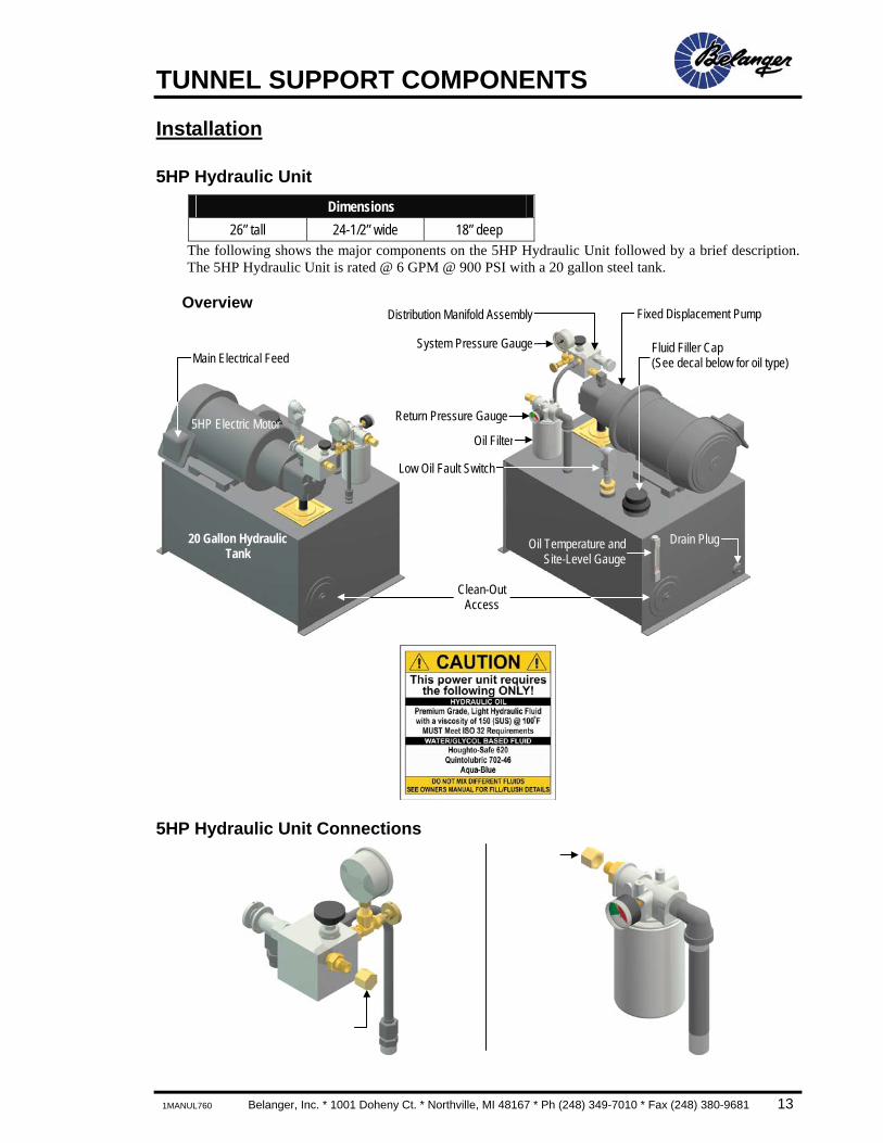
26” tall 24-1/2” wide 18” deep The following shows the major components on the 5HP Hydraulic Unit followed by a brief description. The 5HP Hydraulic Unit is rated @ 6 GPM @ 900 PSI with a 20 gallon steel tank.
Overview
5HP Hydraulic Unit Connections
20 Gallon Hydraulic Tank
5HP Electric Motor
Drain PlugOil Temperature andSite-Level Gauge
Clean-Out Access
Oil Filter
Main Electrical Feed
Return Pressure Gauge
Low Oil Fault Switch
Oil Filler Cap (See decals below for oil type) Fluid Filler Cap (See decal below for oil type)
System Pressure Gauge
Fixed Displacement Pump Distribution Manifold Assembly

TUNNEL SUPPORT COMPONENTS
14 Belanger, Inc. * 1001 Doheny Ct. * Northville, MI 48167 * Ph (248) 349-7010 * Fax (248) 380-9681 1MANUL760
Installation
5HP Hydraulic Unit Manifold
5HP Hydraulic Unit Replacement Parts
1GAUGE250 1FILTR510 1ELECT-SW437 Return Pressure Gauge
System Relief Pressure Adjustment • 900PSI dead-head
Equipment Flow Control • Closed when setting system pressure to 900PSI • Open to adjust equipment speed
System Pressure Gauge • 900PSI set dead-head
Line Out to Equipment • Remove outer cap and feed with
field supplied 1/2” JIC Hydraulic
Snubber • Open to check system pressure • Close to protect gauge
TUNNEL SUPPORT COMPONENTS
1MANUL760 Belanger, Inc. * 1001 Doheny Ct. * Northville, MI 48167 * Ph (248) 349-7010 * Fax (248) 380-9681 15
Installation
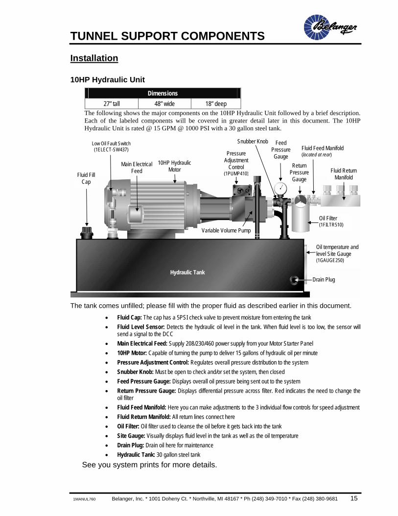
10HP Hydraulic Unit Dimensions
27” tall 48” wide 18” deep The following shows the major components on the 10HP Hydraulic Unit followed by a brief description. Each of the labeled components will be covered in greater detail later in this document. The 10HP Hydraulic Unit is rated @ 15 GPM @ 1000 PSI with a 30 gallon steel tank.
The tank comes unfilled; please fill with the proper fluid as described earlier in this document.
• Fluid Cap: The cap has a 5PSI check valve to prevent moisture from entering the tank • Fluid Level Sensor: Detects the hydraulic oil level in the tank. When fluid level is too low, the sensor will
send a signal to the DCC • Main Electrical Feed: Supply 208/230/460 power supply from your Motor Starter Panel • 10HP Motor: Capable of turning the pump to deliver 15 gallons of hydraulic oil per minute • Pressure Adjustment Control: Regulates overall pressure distribution to the system • Snubber Knob: Must be open to check and/or set the system, then closed • Feed Pressure Gauge: Displays overall oil pressure being sent out to the system • Return Pressure Gauge: Displays differential pressure across filter. Red indicates the need to change the
oil filter • Fluid Feed Manifold: Here you can make adjustments to the 3 individual flow controls for speed adjustment • Fluid Return Manifold: All return lines connect here • Oil Filter: Oil filter used to cleanse the oil before it gets back into the tank • Site Gauge: Visually displays fluid level in the tank as well as the oil temperature • Drain Plug: Drain oil here for maintenance • Hydraulic Tank: 30 gallon steel tank
See you system prints for more details.
Fluid Fill Cap
Main Electrical Feed
Pressure Adjustment
Control (1PUMP410)
Snubber Knob Feed Pressure Gauge
Fluid Feed Manifold (located at rear)
Fluid Return Manifold
Oil temperature and level Site Gauge (1GAUGE250)
Drain Plug Hydraulic Tank
Oil Filter (1FILTR510)
Return Pressure Gauge
10HP Hydraulic Motor
Variable Volume Pump
Low Oil Fault Switch (1ELECT-SW437)
TUNNEL SUPPORT COMPONENTS
16 Belanger, Inc. * 1001 Doheny Ct. * Northville, MI 48167 * Ph (248) 349-7010 * Fax (248) 380-9681 1MANUL760
Installation
10HP Hydraulic Unit
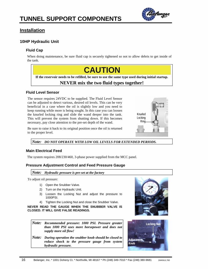
Fluid Cap When doing maintenance, be sure fluid cap is securely tightened so not to allow debris to get inside of the tank.
CAUTION If the reservoir needs to be refilled, be sure to use the same type used during initial startup.
NEVER mix the two fluid types together!
Fluid Level Sensor The sensor requires 24VDC to be supplied. The Fluid Level Sensor can be adjusted to detect various, desired oil levels. This can be very beneficial in a case where the oil is slightly low and you need to keep running while more is being sought. In this case you can loosen the knurled locking ring and slide the wand deeper into the tank. This will prevent the system from shutting down. If this becomes necessary, pay close attention to the pre-set depth of the wand.
Be sure to raise it back to its original position once the oil is returned to the proper level.
Note: DO NOT OPERATE WITH LOW OIL LEVELS FOR EXTENDED PERIODS.
Main Electrical Feed The system requires 208/230/460, 3-phase power supplied from the MCC panel.
Pressure Adjustment Control and Feed Pressure Gauge
Note: Hydraulic pressure is pre-set at the factory
To adjust oil pressure:
1) Open the Snubber Valve. 2) Turn on the Hydraulic Unit. 3) Loosen the Locking Nut and adjust the pressure to
1000PSI. 4) Tighten the Locking Nut and close the Snubber Valve.
NEVER READ THE GAUGE WHEN THE SNUBBER VALVE IS CLOSED. IT WILL GIVE FALSE READINGS.
Note: Recommended pressure: 1000 PSI. Pressure greater than 1000 PSI uses more horsepower and does not supply more oil flow!
Note: During operation the snubber knob should be closed to reduce shock to the pressure gauge from system hydraulic pressure.
Locking Nut
Adjustment Knob
KnurledLocking
Ring
TUNNEL SUPPORT COMPONENTS
1MANUL760 Belanger, Inc. * 1001 Doheny Ct. * Northville, MI 48167 * Ph (248) 349-7010 * Fax (248) 380-9681 17
Installation
10HP Hydraulic Unit
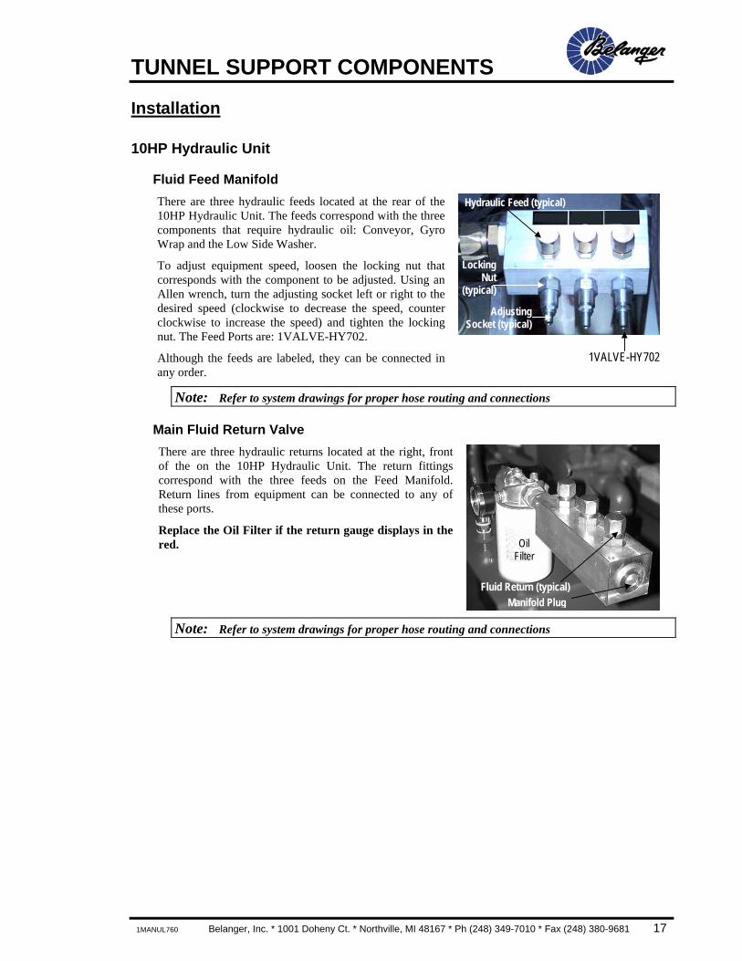
Fluid Feed Manifold There are three hydraulic feeds located at the rear of the 10HP Hydraulic Unit. The feeds correspond with the three components that require hydraulic oil: Conveyor, Gyro Wrap and the Low Side Washer.
To adjust equipment speed, loosen the locking nut that corresponds with the component to be adjusted. Using an Allen wrench, turn the adjusting socket left or right to the desired speed (clockwise to decrease the speed, counter clockwise to increase the speed) and tighten the locking nut. The Feed Ports are: 1VALVE-HY702.
Although the feeds are labeled, they can be connected in any order.
1VALVE-HY702
Note: Refer to system drawings for proper hose routing and connections
Main Fluid Return Valve There are three hydraulic returns located at the right, front of the on the 10HP Hydraulic Unit. The return fittings correspond with the three feeds on the Feed Manifold. Return lines from equipment can be connected to any of these ports.
Replace the Oil Filter if the return gauge displays in the red.
Note: Refer to system drawings for proper hose routing and connections
Hydraulic Feed (typical)
LockingNut
(typical)
AdjustingSocket (typical)
Oil Filter
Fluid Return (typical)Manifold Plug
TUNNEL SUPPORT COMPONENTS
18 Belanger, Inc. * 1001 Doheny Ct. * Northville, MI 48167 * Ph (248) 349-7010 * Fax (248) 380-9681 1MANUL760
Installation
20HP Hydraulic Unit Dimensions
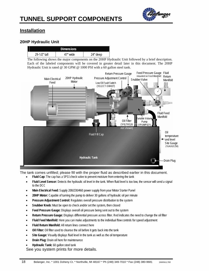
29-1/2” tall 47” wide 24” deep The following shows the major components on the 20HP Hydraulic Unit followed by a brief description. Each of the labeled components will be covered in greater detail later in this document. The 20HP Hydraulic Unit is rated @ 30 GPM @ 1000 PSI with a 60 gallon steel tank.
The tank comes unfilled; please fill with the proper fluid as described earlier in this document.
• Fluid Cap: The cap has a 5PSI check valve to prevent moisture from entering the tank • Fluid Level Sensor: Detects the hydraulic oil level in the tank. When fluid level is too low, the sensor will send a signal
to the DCC • Main Electrical Feed: Supply 208/230/460 power supply from your Motor Starter Panel • 20HP Motor: Capable of turning the pump to deliver 30 gallons of hydraulic oil per minute • Pressure Adjustment Control: Regulates overall pressure distribution to the system • Snubber Knob: Must be open to check and/or set the system, then closed • Feed Pressure Gauge: Displays overall oil pressure being sent out to the system • Return Pressure Gauge: Displays differential pressure across filter. Red indicates the need to change the oil filter • Fluid Feed Manifold: Here you can make adjustments to the individual flow controls for speed adjustment • Fluid Return Manifold: All return lines connect here • Oil Filter: Oil filter used to cleanse the oil before it gets back into the tank • Site Gauge: Visually displays fluid level in the tank as well as the oil temperature • Drain Plug: Drain oil here for maintenance • Hydraulic Tank: 60 gallon steel tank See you system prints for more details.
Fluid Fill Cap
Main Electrical Feed
Pressure Adjustment ControlFeed Pressure Gauge(mounted on Feed Manifold)
Fluid Feed Manifold
Fluid Return Manifold
Drain Plug Hydraulic Tank
Oil Filter (1FILTR520 not shown)
Return Pressure Gauge20HP Hydraulic
Motor
Variable VolumePump
(1PUMP421)
Snubber Valve
Oil temperature and level Site Gauge (1GAUGE250)
Low Oil Fault Switch (1ELECT-SW437)
TUNNEL SUPPORT COMPONENTS
1MANUL760 Belanger, Inc. * 1001 Doheny Ct. * Northville, MI 48167 * Ph (248) 349-7010 * Fax (248) 380-9681 19
Installation
20HP Hydraulic Unit
Fluid Cap When doing maintenance, be sure fluid cap is securely tightened so not to allow debris to get inside of the tank.
CAUTION If the reservoir needs to be refilled, be sure to use the same type used during initial startup.
NEVER mix the two fluid types together!
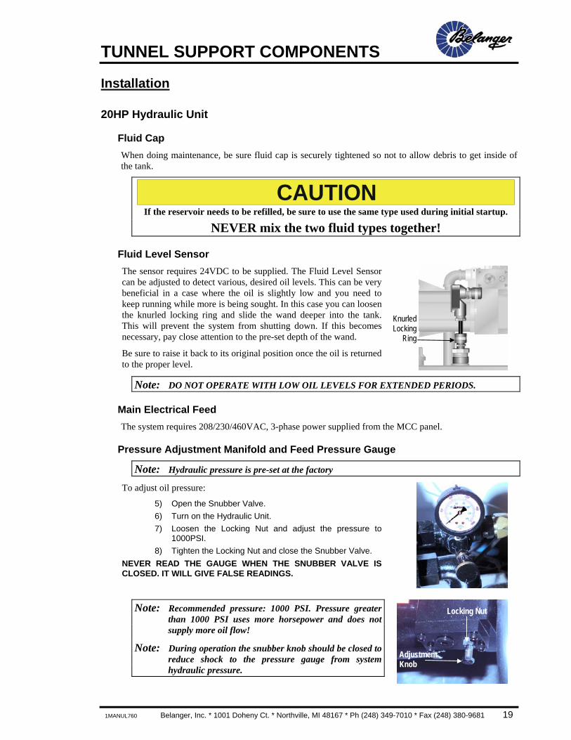
Fluid Level Sensor The sensor requires 24VDC to be supplied. The Fluid Level Sensor can be adjusted to detect various, desired oil levels. This can be very beneficial in a case where the oil is slightly low and you need to keep running while more is being sought. In this case you can loosen the knurled locking ring and slide the wand deeper into the tank. This will prevent the system from shutting down. If this becomes necessary, pay close attention to the pre-set depth of the wand.
Be sure to raise it back to its original position once the oil is returned to the proper level.
Note: DO NOT OPERATE WITH LOW OIL LEVELS FOR EXTENDED PERIODS.
Main Electrical Feed The system requires 208/230/460VAC, 3-phase power supplied from the MCC panel.
Pressure Adjustment Manifold and Feed Pressure Gauge
Note: Hydraulic pressure is pre-set at the factory
To adjust oil pressure:
5) Open the Snubber Valve. 6) Turn on the Hydraulic Unit. 7) Loosen the Locking Nut and adjust the pressure to
1000PSI. 8) Tighten the Locking Nut and close the Snubber Valve.
NEVER READ THE GAUGE WHEN THE SNUBBER VALVE IS CLOSED. IT WILL GIVE FALSE READINGS.
Note: Recommended pressure: 1000 PSI. Pressure greater than 1000 PSI uses more horsepower and does not supply more oil flow!
Note: During operation the snubber knob should be closed to reduce shock to the pressure gauge from system hydraulic pressure.
KnurledLocking
Ring
Locking Nut
Adjustment Knob
TUNNEL SUPPORT COMPONENTS
20 Belanger, Inc. * 1001 Doheny Ct. * Northville, MI 48167 * Ph (248) 349-7010 * Fax (248) 380-9681 1MANUL760
Installation
20HP Hydraulic Unit
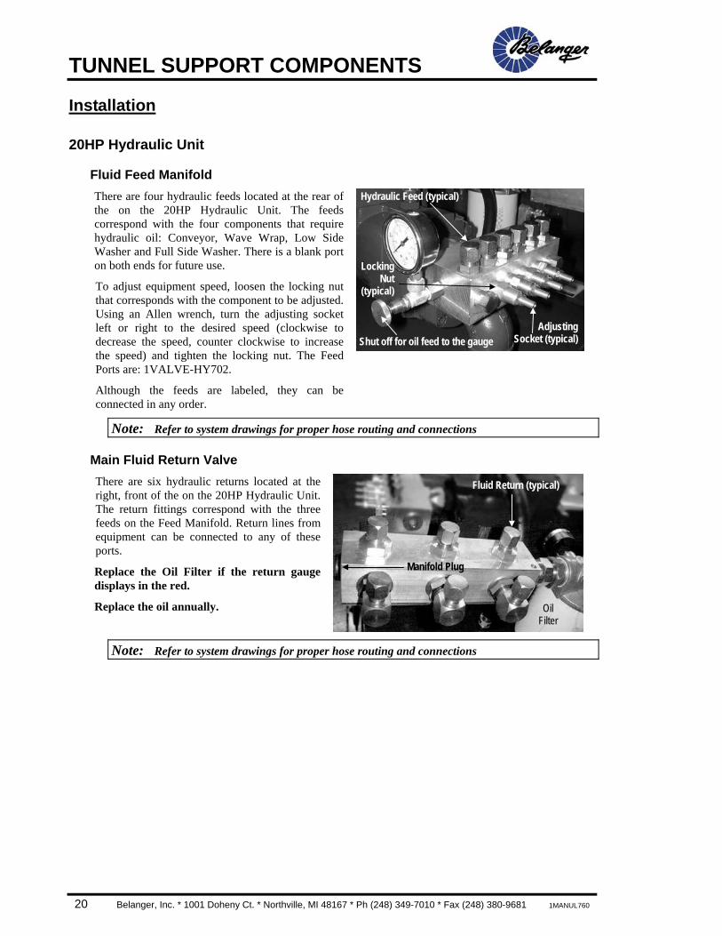
Fluid Feed Manifold There are four hydraulic feeds located at the rear of the on the 20HP Hydraulic Unit. The feeds correspond with the four components that require hydraulic oil: Conveyor, Wave Wrap, Low Side Washer and Full Side Washer. There is a blank port on both ends for future use.
To adjust equipment speed, loosen the locking nut that corresponds with the component to be adjusted. Using an Allen wrench, turn the adjusting socket left or right to the desired speed (clockwise to decrease the speed, counter clockwise to increase the speed) and tighten the locking nut. The Feed Ports are: 1VALVE-HY702.
Although the feeds are labeled, they can be connected in any order.
Note: Refer to system drawings for proper hose routing and connections
Main Fluid Return Valve There are six hydraulic returns located at the right, front of the on the 20HP Hydraulic Unit. The return fittings correspond with the three feeds on the Feed Manifold. Return lines from equipment can be connected to any of these ports.
Replace the Oil Filter if the return gauge displays in the red.
Replace the oil annually.
Note: Refer to system drawings for proper hose routing and connections
Oil Filter
Fluid Return (typical)
Manifold Plug
Hydraulic Feed (typical)
LockingNut
(typical)
AdjustingSocket (typical)Shut off for oil feed to the gauge

TUNNEL SUPPORT COMPONENTS
1MANUL760 Belanger, Inc. * 1001 Doheny Ct. * Northville, MI 48167 * Ph (248) 349-7010 * Fax (248) 380-9681 21
Installation
Pneumatic Air- Panel Overview There are two available Air-Panels for the Dura-Trans™ Classic Conveyor. Confirm that you have the correct Air-Panel to fit your application. If you have concerns, contact your nearest Belanger Representative.
102066 102006 Air-Support System Panel Optional Roller-Up Panel
This panel ships standard with all systems such as: Enduro 60™, Pro 100™, insta-KLEEN™ and Global
40™ The Main System Air Filter/Regulator will feed other
pieces of equipment in the system
This panel ships standard with all Dura-Trans™ Classic Entrance Sections
The Regulator and 4-Way Valve will feed the Roller-Up Cylinder
Dimensions 10-1/2” tall 19” wide 4-3/4” deep
Pneumatic Panels are used to distribute the correct amount of pneumatic pressure to a given component at the correct time and intervals in order to follow the sequence programmed at the controller. Your system can have as few as 2 Pneumatic Panels or as many as 8.
The Enduro Class 60 system comes with the following panels: • Conveyor, Part #102098 • Gyro Wrap®, Part #102022
The Pro Class 100 system comes with the following panels: • Conveyor, Part #102098 • Wave Full Side Washer®, Part #102060 • Wave Wrap® driver side, Part #102025 • Wave Wrap® passenger side, Part #102026
Panel utility installation and adjustments are covered in their corresponding component manual.
TUNNEL SUPPORT COMPONENTS
22 Belanger, Inc. * 1001 Doheny Ct. * Northville, MI 48167 * Ph (248) 349-7010 * Fax (248) 380-9681 1MANUL760
Installation
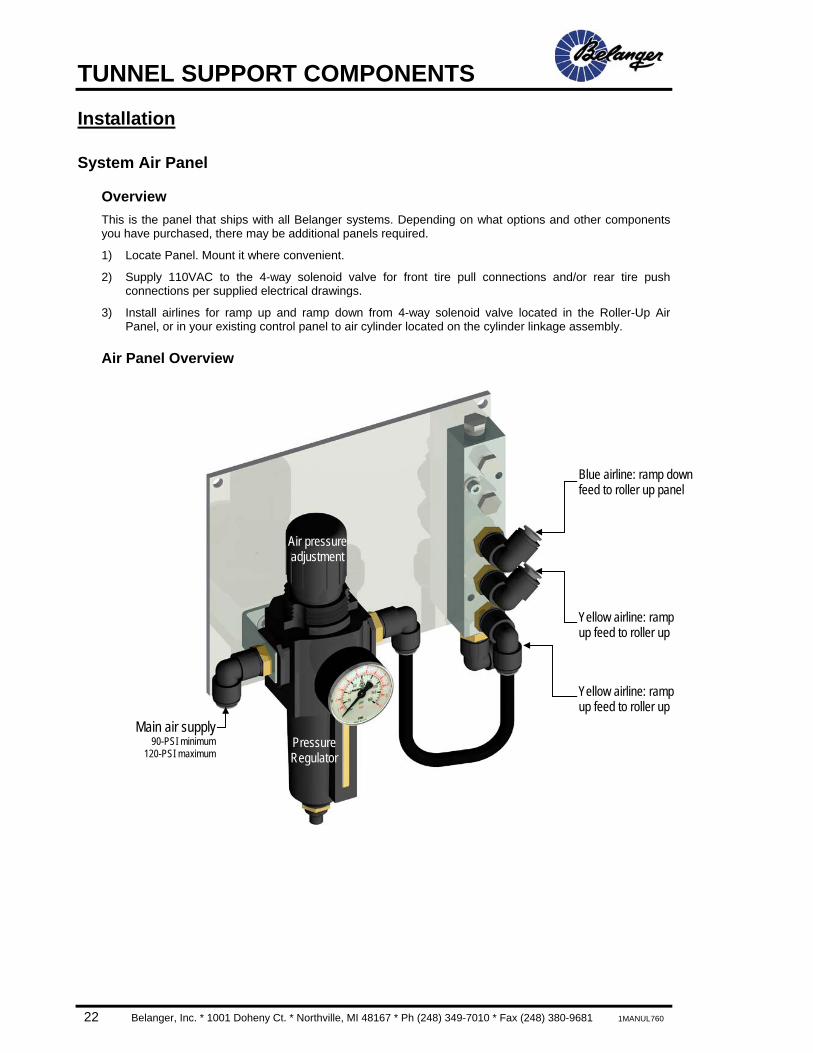
System Air Panel
Overview This is the panel that ships with all Belanger systems. Depending on what options and other components you have purchased, there may be additional panels required.
1) Locate Panel. Mount it where convenient.
2) Supply 110VAC to the 4-way solenoid valve for front tire pull connections and/or rear tire push connections per supplied electrical drawings.
3) Install airlines for ramp up and ramp down from 4-way solenoid valve located in the Roller-Up Air Panel, or in your existing control panel to air cylinder located on the cylinder linkage assembly.
Air Panel Overview
Yellow airline: ramp up feed to roller up
Blue airline: ramp down feed to roller up panel
Main air supply90-PSI minimum
120-PSI maximumPressure Regulator
Air pressure adjustment
Yellow airline: ramp up feed to roller up
TUNNEL SUPPORT COMPONENTS
1MANUL760 Belanger, Inc. * 1001 Doheny Ct. * Northville, MI 48167 * Ph (248) 349-7010 * Fax (248) 380-9681 23
Installation
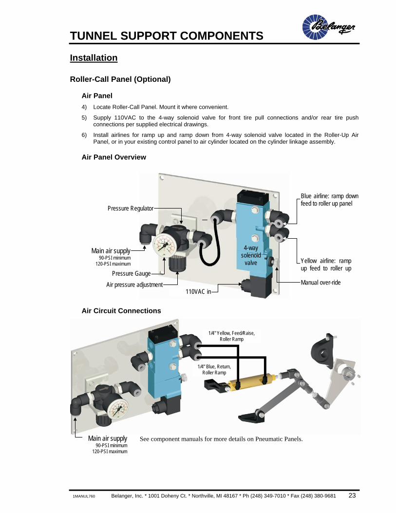
Roller-Call Panel (Optional)
Air Panel 4) Locate Roller-Call Panel. Mount it where convenient.
5) Supply 110VAC to the 4-way solenoid valve for front tire pull connections and/or rear tire push connections per supplied electrical drawings.
6) Install airlines for ramp up and ramp down from 4-way solenoid valve located in the Roller-Up Air Panel, or in your existing control panel to air cylinder located on the cylinder linkage assembly.
Air Panel Overview
Air Circuit Connections
See component manuals for more details on Pneumatic Panels.
1/4" Yellow, Feed/Raise, Roller Ramp
1/4" Blue, Return, Roller Ramp
4-way solenoid
valve Yellow airline: rampup feed to roller up
Blue airline: ramp downfeed to roller up panel
110VAC in
Main air supply90-PSI minimum
120-PSI maximum
Pressure Regulator
Manual over-ride Air pressure adjustmentPressure Gauge
Main air supply90-PSI minimum
120-PSI maximum

TUNNEL SUPPORT COMPONENTS
24 Belanger, Inc. * 1001 Doheny Ct. * Northville, MI 48167 * Ph (248) 349-7010 * Fax (248) 380-9681 1MANUL760
Installation
Pneumatic Panels
Inspection and Cleaning There are two filters to be inspected and cleaned. The Main Filter and the Coalescent Filter. Both located on the side of the MCC.
1) Turn OFF the air supply to the Filter Assembly. 2) Remove the bowl of the Main Filter by lifting up and turning clockwise while looking down on it. 3) Remove the “star shaped” nut and the white, tapered filter element. Clean both of these
components. Notice that the white filter element is positioned “wide side up”. 4) Remove the float from inside of the bowl and clean it. Notice the float is positioned “star side
down”. 5) Wash out the inside of the bowl. You may need to disassemble the valve assembly if it appears
clogged. 6) Reassemble the Main Filter. 7) Remove the bowl of the Coalescent Filter by lifting up and turning counter-clockwise. 8) Remove the green, foam covered filter element. Clean it. 9) Wash out the inside of the bowl. You may need to disassemble the valve assembly if it appears
clogged. 10) Reassemble the Coalescent Filter.
Removing bowls from
filter Star Shaped Nut and
Tapered Filter Element Bowl Assembly
Valve Assembly
Main Filter
1FRL-SP400
TUNNEL SUPPORT COMPONENTS
1MANUL760 Belanger, Inc. * 1001 Doheny Ct. * Northville, MI 48167 * Ph (248) 349-7010 * Fax (248) 380-9681 25
Installation
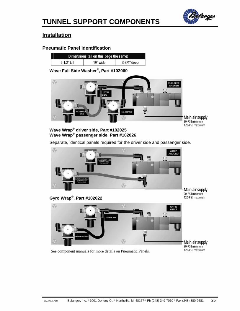
Pneumatic Panel Identification Dimensions (all on this page the same)
6-1/2” tall 19” wide 3-3/4” deep
Wave Full Side Washer®, Part #102060
Wave Wrap® driver side, Part #102025 Wave Wrap® passenger side, Part #102026 Separate, identical panels required for the driver side and passenger side.
Gyro Wrap®, Part #102022
See component manuals for more details on Pneumatic Panels.
Main air supply 90-PSI minimum 120-PSI maximum
Main air supply 90-PSI minimum 120-PSI maximum
Main air supply 90-PSI minimum 120-PSI maximum

TUNNEL SUPPORT COMPONENTS
26 Belanger, Inc. * 1001 Doheny Ct. * Northville, MI 48167 * Ph (248) 349-7010 * Fax (248) 380-9681 1MANUL760
Installation
32 Output Controller Dimensions
36” tall 36” wide 9” deep The 32 Output Controller has 32 inputs available and 32 outputs. This unit is capable of controlling a typical Enduro Class 60 wash system. If options are added to the base package it may be necessary to option for the DCC 64 Output Controller. See prints for installation and utility connections. See DCC / E-300 Operators Station manuals for more details on the DCC.
Component Identification
CB1 - Processor CB2 – Modem (GFCI Outlet)
CB4 - 24 Volt DC
CB3 - 24-Volt Power Supply
Circuit Breakers
24-Volt Power Supply Control Relays Terminal Strip
CR1 - GFCICR2 - Wash In Use
MCR - Master Control Relay
Terminal Strip
Processor
GFCI Breaker
Modem Power
In Out Out
Input Board DCC32 / DCC64
Output Board DCC32 / DCC64
TUNNEL SUPPORT COMPONENTS
1MANUL760 Belanger, Inc. * 1001 Doheny Ct. * Northville, MI 48167 * Ph (248) 349-7010 * Fax (248) 380-9681 27
Installation
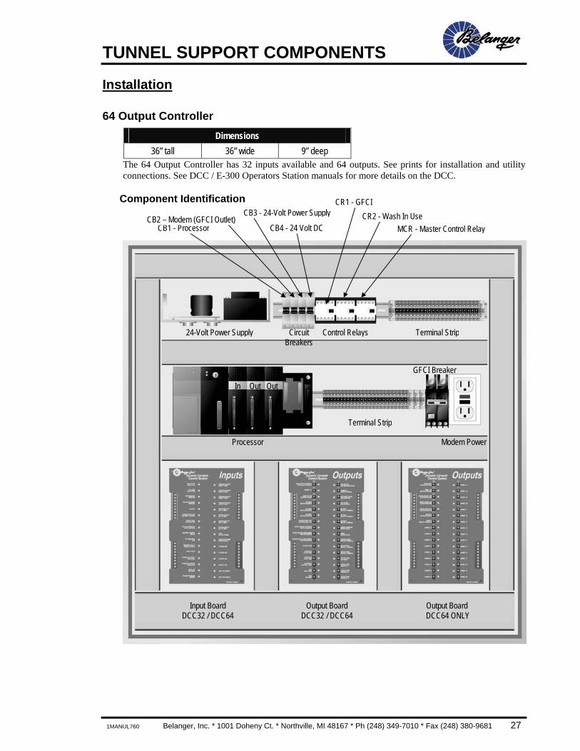
64 Output Controller Dimensions
36” tall 36” wide 9” deep The 64 Output Controller has 32 inputs available and 64 outputs. See prints for installation and utility connections. See DCC / E-300 Operators Station manuals for more details on the DCC.
Component Identification
CB1 - ProcessorCB2 – Modem (GFCI Outlet)
CB4 - 24 Volt DC
CB3 - 24-Volt Power Supply
Circuit Breakers
24-Volt Power Supply Control Relays Terminal Strip
CR1 - GFCICR2 - Wash In Use
MCR - Master Control Relay
Terminal Strip
Processor
GFCI Breaker
Modem Power
In Out Out
Input Board DCC32 / DCC64
Output Board DCC32 / DCC64
Output Board DCC64 ONLY
TUNNEL SUPPORT COMPONENTS
28 Belanger, Inc. * 1001 Doheny Ct. * Northville, MI 48167 * Ph (248) 349-7010 * Fax (248) 380-9681 1MANUL760
Installation
Motor Starter Panel Dimensions
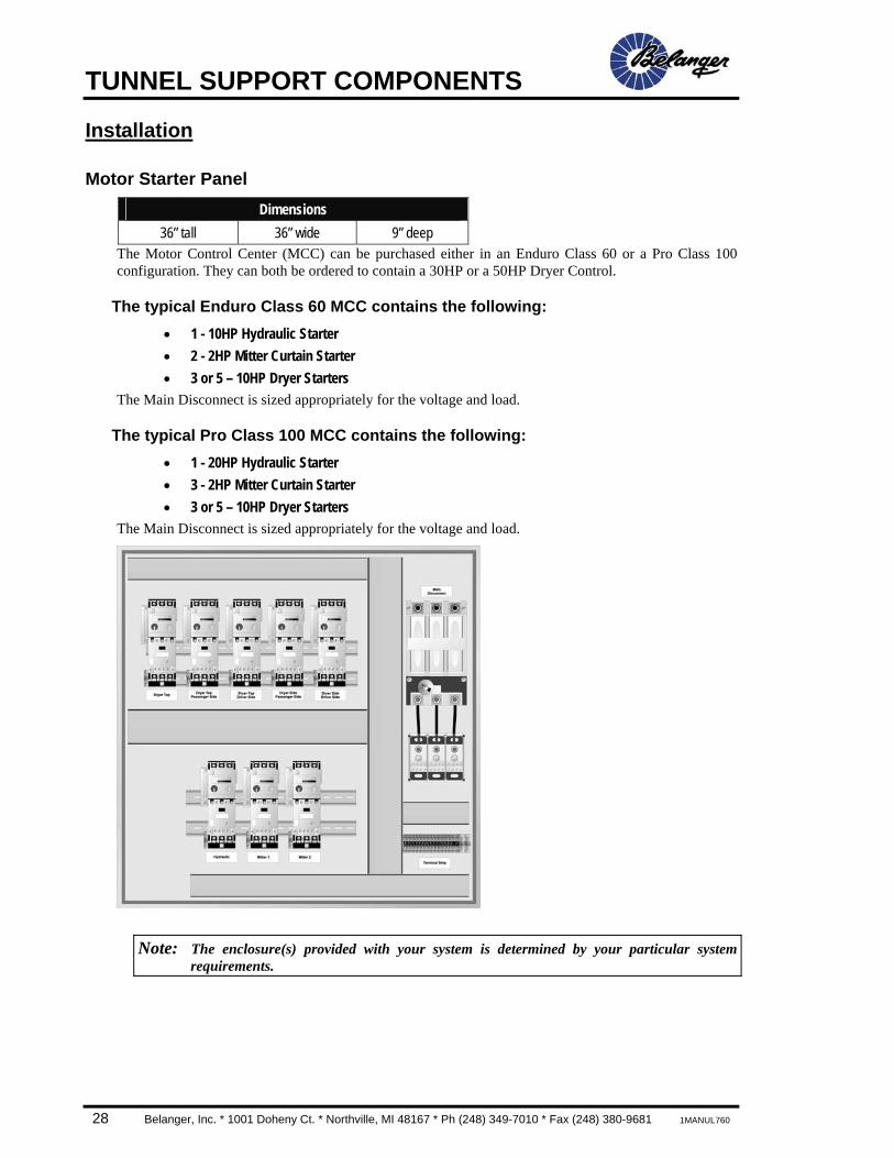
36” tall 36” wide 9” deep The Motor Control Center (MCC) can be purchased either in an Enduro Class 60 or a Pro Class 100 configuration. They can both be ordered to contain a 30HP or a 50HP Dryer Control.
The typical Enduro Class 60 MCC contains the following: • 1 - 10HP Hydraulic Starter • 2 - 2HP Mitter Curtain Starter • 3 or 5 – 10HP Dryer Starters
The Main Disconnect is sized appropriately for the voltage and load.
The typical Pro Class 100 MCC contains the following: • 1 - 20HP Hydraulic Starter • 3 - 2HP Mitter Curtain Starter • 3 or 5 – 10HP Dryer Starters
The Main Disconnect is sized appropriately for the voltage and load.
Note: The enclosure(s) provided with your system is determined by your particular system requirements.

TUNNEL SUPPORT COMPONENTS
1MANUL760 Belanger, Inc. * 1001 Doheny Ct. * Northville, MI 48167 * Ph (248) 349-7010 * Fax (248) 380-9681 29
Installation
Attended Operator Station (1515 Button Box) Dimensions (while facing keypad)
11-3/4” tall 13-1/2” wide 6-3/4” deep The Operator Station will have to be field wired. A service technician is to puncture a hole in the desired location (preferably not on the face), run conduit and wire according to the electrical prints supplied with your system.
Usage The Operator Station is fairly straightforward. Press the keypad to activate the Packages/Options desired. For a given vehicle, you can put into Stand-By a single Package and up to 15 Options. Once selections have been made, press the ACCEPT key to move to QUEUE. If a mistake has been made before the ACCEPT key has been pressed, press the Package key to start over. If a mistake has been made and the ACCEPT key has already been pressed, press and hold the ACCEPT key for 3 seconds to reset the QUEUE.
To print receipts, after making the selection for a customer, press the ACCEPT key for 1/2 second. Be careful not to hold this key for 3 seconds. Doing so will reset the QUEUE.
To print reports, press and hold the appropriate key near the bottom left of the keypad before pressing any of the Package keys and the corresponding report will print. This Function only works if Stand-By is clear.
The label spaces are designed to accommodate standard Avery 1/2” labels.
E-Stop
Keypad
Label Space (typical)

TUNNEL SUPPORT COMPONENTS
30 Belanger, Inc. * 1001 Doheny Ct. * Northville, MI 48167 * Ph (248) 349-7010 * Fax (248) 380-9681 1MANUL760
Installation
Attended Operator Station (1515 Button Box)
Schematic
TUNNEL SUPPORT COMPONENTS
1MANUL760 Belanger, Inc. * 1001 Doheny Ct. * Northville, MI 48167 * Ph (248) 349-7010 * Fax (248) 380-9681 31
Installation
Solution Delivery Module (SDM) General Dimensions
33” tall 34” wide 14-1/2” deep This section will explain the features of the SDM. Some items may differ from your site. See you site specific prints for details.
Overview Each water valve requires a channel from one of the Output Modules. All water valves can be used on either the front or rear manifold of the SDM panel and can be moved from front to rear at any time. They are also interchangeable as long as the appropriate style is being used for a specific duty.
A single SDM can have as few as 4 water valves or as many as 8. Additional water valves can be easily added at anytime as long as there is room on the manifold to accommodate them.
Each bank of water valves can be supplied with different types of water, (fresh, reclaim or hot water).
Note: Foamer Style Water Valves are designed to use only fresh water.
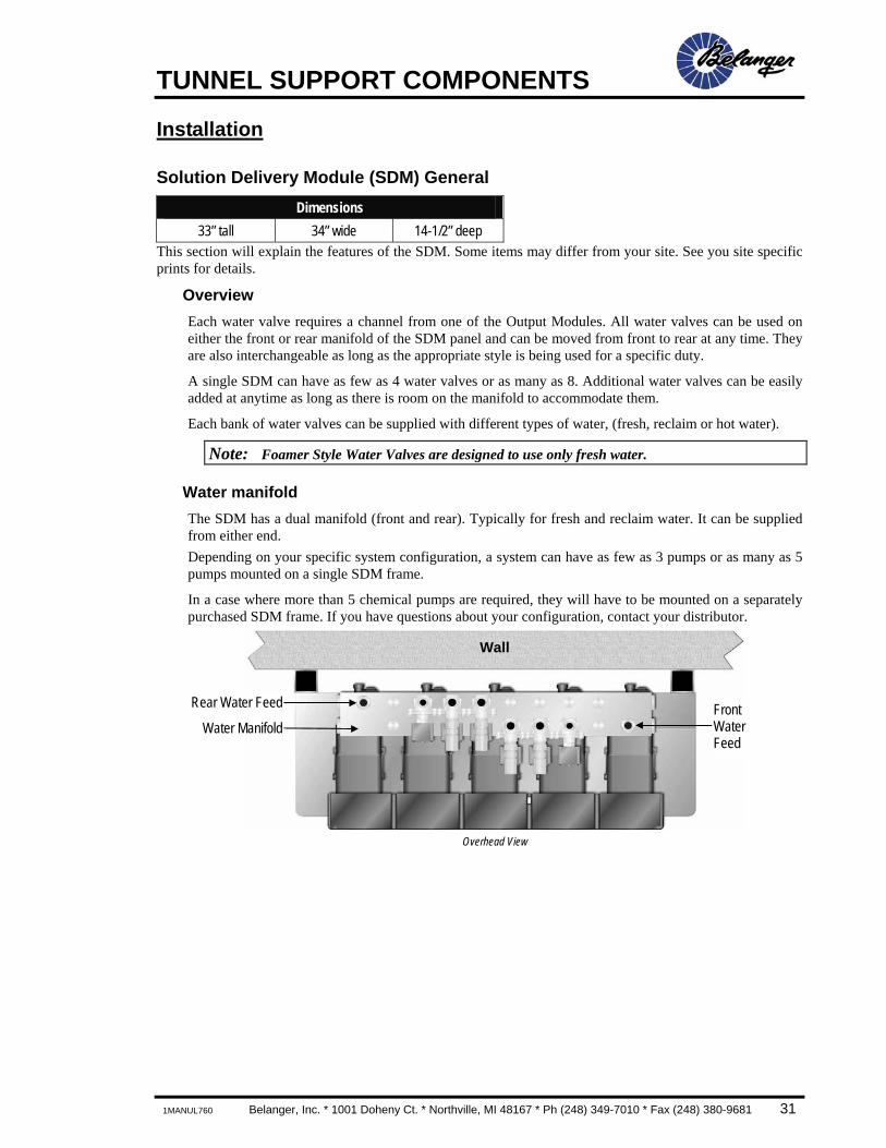
Water manifold The SDM has a dual manifold (front and rear). Typically for fresh and reclaim water. It can be supplied from either end. Depending on your specific system configuration, a system can have as few as 3 pumps or as many as 5 pumps mounted on a single SDM frame.
In a case where more than 5 chemical pumps are required, they will have to be mounted on a separately purchased SDM frame. If you have questions about your configuration, contact your distributor.
Overhead View
Wall
Rear Water Feed Front Water Feed
Water Manifold
TUNNEL SUPPORT COMPONENTS
32 Belanger, Inc. * 1001 Doheny Ct. * Northville, MI 48167 * Ph (248) 349-7010 * Fax (248) 380-9681 1MANUL760
Installation
Solution Delivery Module (SDM) General
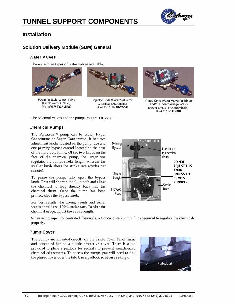
Water Valves There are three types of water valves available.
Foaming Style Water Valve
(Fresh water ONLY!), Part #VLV FOAMING
Injector Style Water Valve for
Chemical Dispensing, Part #VLV INJECTOR
Rinse Style Water Valve for Rinse
and/or Undercarriage Wash (Water ONLY, NO chemicals),
Part #VLV RINSE
The solenoid valves and the pumps require 110VAC.
Chemical Pumps The Pulsatron™ pump can be either Hyper Concentrate or Super Concentrate. It has two adjustment knobs located on the pump face and one priming bypass control located on the base of the fluid output line. Of the two knobs on the face of the chemical pump, the larger one regulates the pumps stroke length, whereas the smaller knob alters the stroke rate (cycles per minute).
To prime the pump, fully open the bypass knob. This will shorten the fluid path and allow the chemical to loop directly back into the chemical drum. Once the pump has been primed, close the bypass knob.
For best results, the drying agents and sealer waxes should use 100% stroke rate. To alter the chemical usage, adjust the stroke length.
When using super concentrated chemicals, a Concentrate Pump will be required to regulate the chemicals properly.
Pump Cover The pumps are mounted directly on the Triple Foam Panel frame and concealed behind a plastic protective cover. There is a tab provided to place a padlock for security to prevent unauthorized chemical adjustments. To access the pumps you will need to flex the plastic cover over the tab. Use a padlock so secure settings.
PrimingBypass Feed back
to chemical drum
Stroke Rate
StrokeLength
Fluid outputline
110VACFeed
DO NOT ADJUST THISKNOB UNLESS THE PUMP IS RUNNING
Padlock tab

TUNNEL SUPPORT COMPONENTS
1MANUL760 Belanger, Inc. * 1001 Doheny Ct. * Northville, MI 48167 * Ph (248) 349-7010 * Fax (248) 380-9681 33
Installation
Solution Delivery Module (SDM) General
Electrical Distribution Block This section will explain all feeds to and from the Electrical Distribution Block located on the SDM. The Electrical Distribution Block is where the connections are made to the SDM from the MCC.
There are two types of plugs that can connect to this block, a single and a dual plug. Depending on your purchased options, you may have either type in a given location. The image below shows destination of dual plug feeds.
Single Dual
Electrical Distribution Block Requires an 110VAC feed from DCC output.
SDM feed from DCC
output
TUNNEL SUPPORT COMPONENTS
34 Belanger, Inc. * 1001 Doheny Ct. * Northville, MI 48167 * Ph (248) 349-7010 * Fax (248) 380-9681 1MANUL760
Installation
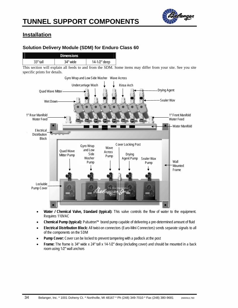
Solution Delivery Module (SDM) for Enduro Class 60 Dimensions
33” tall 34” wide 14-1/2” deep This section will explain all feeds to and from the SDM. Some items may differ from your site. See you site specific prints for details.
• Water / Chemical Valve, Standard (typical): This valve controls the flow of water to the equipment.
Requires 110VAC • Chemical Pump (typical): Pulsatron™ brand pump capable of delivering a pre-determined amount of fluid • Electrical Distribution Block: All twist-on connectors (Euro-Mini Connectors) sends separate signals to all
of the components on the SDM • Pump Cover: Cover can be locked to prevent tampering with a padlock at the post • Frame: The frame is 34” wide x 24” tall x 14-1/2” deep (including cover) and should be mounted in a back
room using 1/2” wall anchors
Wall Mounted Frame
Sealer Wax Pump
WaveAcrossPump
Cover Locking Post
Gyro Wrap and Low Side Washer
ElectricalDistribution
Block
1” Rear ManifoldWater Feed
LockablePump Cover
Drying Agent Pump
Quad WaveMitter Pump
Wave Across
Drying Agent
1” Front Manifold Water Feed
Water Manifold
Quad Wave Mitter
Sealer Wav Wet Down
Undercarriage Wash Rinse Arch
Gyro Wrapand Low
SideWasher
Pump
TUNNEL SUPPORT COMPONENTS
1MANUL760 Belanger, Inc. * 1001 Doheny Ct. * Northville, MI 48167 * Ph (248) 349-7010 * Fax (248) 380-9681 35
Installation
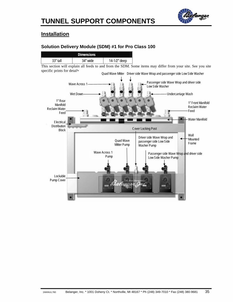
Solution Delivery Module (SDM) #1 for Pro Class 100 Dimensions
33” tall 34” wide 14-1/2” deep This section will explain all feeds to and from the SDM. Some items may differ from your site. See you site specific prints for details.
Wall Mounted Frame
Wave Across 1Pump
Quad WaveMitter Pump
Cover Locking Post
Quad Wave Mitter
ElectricalDistribution
Block
1” RearManifold
Reclaim WaterFeed
LockablePump Cover
Driver side Wave Wrap and passenger side Low Side Washer Pump
Driver side Wave Wrap and passenger side Low Side Washer
1” Front Manifold Reclaim Water Feed
Water Manifold
Wave Across 1
Undercarriage Wash Wet Down
Passenger side Wave Wrap and driver side Low Side Washer Pump
Passenger side Wave Wrap and driver side Low Side Washer
TUNNEL SUPPORT COMPONENTS
36 Belanger, Inc. * 1001 Doheny Ct. * Northville, MI 48167 * Ph (248) 349-7010 * Fax (248) 380-9681 1MANUL760
Installation
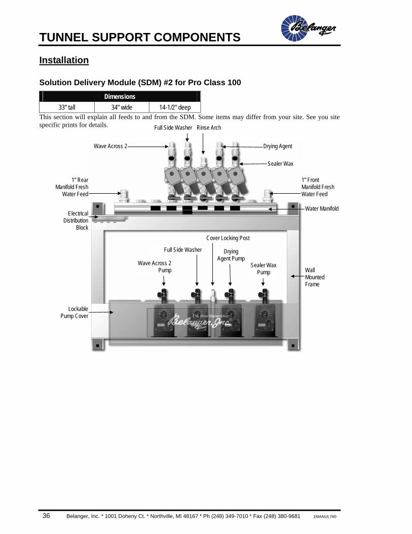
Solution Delivery Module (SDM) #2 for Pro Class 100 Dimensions
33” tall 34” wide 14-1/2” deep This section will explain all feeds to and from the SDM. Some items may differ from your site. See you site specific prints for details.
Wall Mounted Frame
Wave Across 2Pump
Sealer Wax Pump
Full Side Washer
Cover Locking Post
Full Side Washer
ElectricalDistribution
Block
1” RearManifold Fresh
Water Feed
LockablePump Cover
Drying Agent Pump
Rinse Arch
Drying Agent
1” Front Manifold Fresh Water Feed
Water Manifold
Wave Across 2
Sealer Wax
TUNNEL SUPPORT COMPONENTS
1MANUL760 Belanger, Inc. * 1001 Doheny Ct. * Northville, MI 48167 * Ph (248) 349-7010 * Fax (248) 380-9681 37
Installation
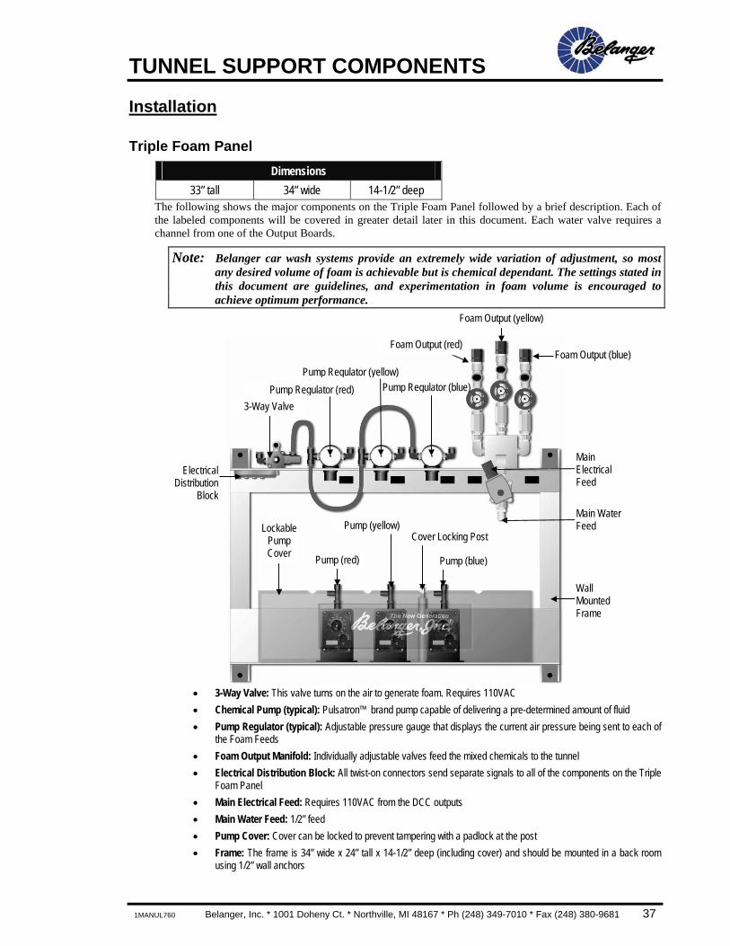
Triple Foam Panel Dimensions
33” tall 34” wide 14-1/2” deep The following shows the major components on the Triple Foam Panel followed by a brief description. Each of the labeled components will be covered in greater detail later in this document. Each water valve requires a channel from one of the Output Boards.
Note: Belanger car wash systems provide an extremely wide variation of adjustment, so most any desired volume of foam is achievable but is chemical dependant. The settings stated in this document are guidelines, and experimentation in foam volume is encouraged to achieve optimum performance.
• 3-Way Valve: This valve turns on the air to generate foam. Requires 110VAC • Chemical Pump (typical): Pulsatron™ brand pump capable of delivering a pre-determined amount of fluid • Pump Regulator (typical): Adjustable pressure gauge that displays the current air pressure being sent to each of
the Foam Feeds • Foam Output Manifold: Individually adjustable valves feed the mixed chemicals to the tunnel • Electrical Distribution Block: All twist-on connectors send separate signals to all of the components on the Triple
Foam Panel • Main Electrical Feed: Requires 110VAC from the DCC outputs • Main Water Feed: 1/2” feed • Pump Cover: Cover can be locked to prevent tampering with a padlock at the post • Frame: The frame is 34” wide x 24” tall x 14-1/2” deep (including cover) and should be mounted in a back room
using 1/2” wall anchors
Pump Regulator (red)3-Way Valve
LockablePump Cover
Wall Mounted Frame
Pump (red) Pump (blue)
Pump (yellow)Cover Locking Post
Pump Regulator (yellow)Pump Regulator (blue)
Foam Output (blue)
Foam Output (yellow)
Foam Output (red)
Main Water Feed
Main Electrical Feed
ElectricalDistribution
Block
TUNNEL SUPPORT COMPONENTS
38 Belanger, Inc. * 1001 Doheny Ct. * Northville, MI 48167 * Ph (248) 349-7010 * Fax (248) 380-9681 1MANUL760
Installation
Triple Foam Panel
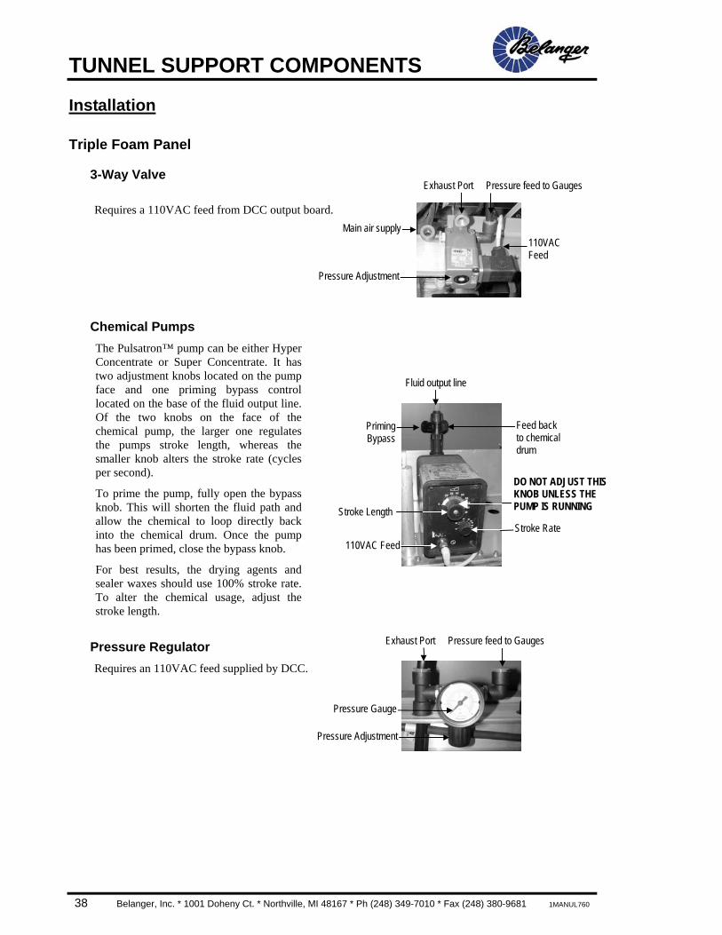
3-Way Valve
Requires a 110VAC feed from DCC output board.
Chemical Pumps The Pulsatron™ pump can be either Hyper Concentrate or Super Concentrate. It has two adjustment knobs located on the pump face and one priming bypass control located on the base of the fluid output line. Of the two knobs on the face of the chemical pump, the larger one regulates the pumps stroke length, whereas the smaller knob alters the stroke rate (cycles per second).
To prime the pump, fully open the bypass knob. This will shorten the fluid path and allow the chemical to loop directly back into the chemical drum. Once the pump has been primed, close the bypass knob.
For best results, the drying agents and sealer waxes should use 100% stroke rate. To alter the chemical usage, adjust the stroke length.
Pressure Regulator Requires an 110VAC feed supplied by DCC.
110VAC Feed
Exhaust Port
Main air supply
Pressure Adjustment
Pressure feed to Gauges
Pressure Gauge
Pressure Adjustment
Exhaust Port Pressure feed to Gauges
Fluid output line
PrimingBypass
Feed back to chemical drum
Stroke Rate Stroke Length
110VAC Feed
DO NOT ADJUST THIS KNOB UNLESS THE PUMP IS RUNNING

TUNNEL SUPPORT COMPONENTS
1MANUL760 Belanger, Inc. * 1001 Doheny Ct. * Northville, MI 48167 * Ph (248) 349-7010 * Fax (248) 380-9681 39
Installation
Triple Foam Panel
Foam Output Manifold
Pump Cover
The pumps are mounted directly on the Triple Foam Panel frame and concealed behind a plastic protective cover. There is a tab provided to place a padlock for security to prevent unauthorized chemical adjustments. To access the pumps you will need to flex the plastic cover over the tab. Use a padlock so secure settings.
Electrical Terminal Box Requires an 110VAC feed from DCC output board.
Padlock tab
Feed from chemical drum (typical)
Foam out (red)
110VAC feedfrom DCC
output
Main Water Feed
Foam out (blue) Foam out (yellow)
Chemicalflow
controlvalve
(typical) Check Valve (typical)
Solenoid Valve
Feed from DCC
output
TUNNEL SUPPORT COMPONENTS
40 Belanger, Inc. * 1001 Doheny Ct. * Northville, MI 48167 * Ph (248) 349-7010 * Fax (248) 380-9681 1MANUL760
Replacement Parts
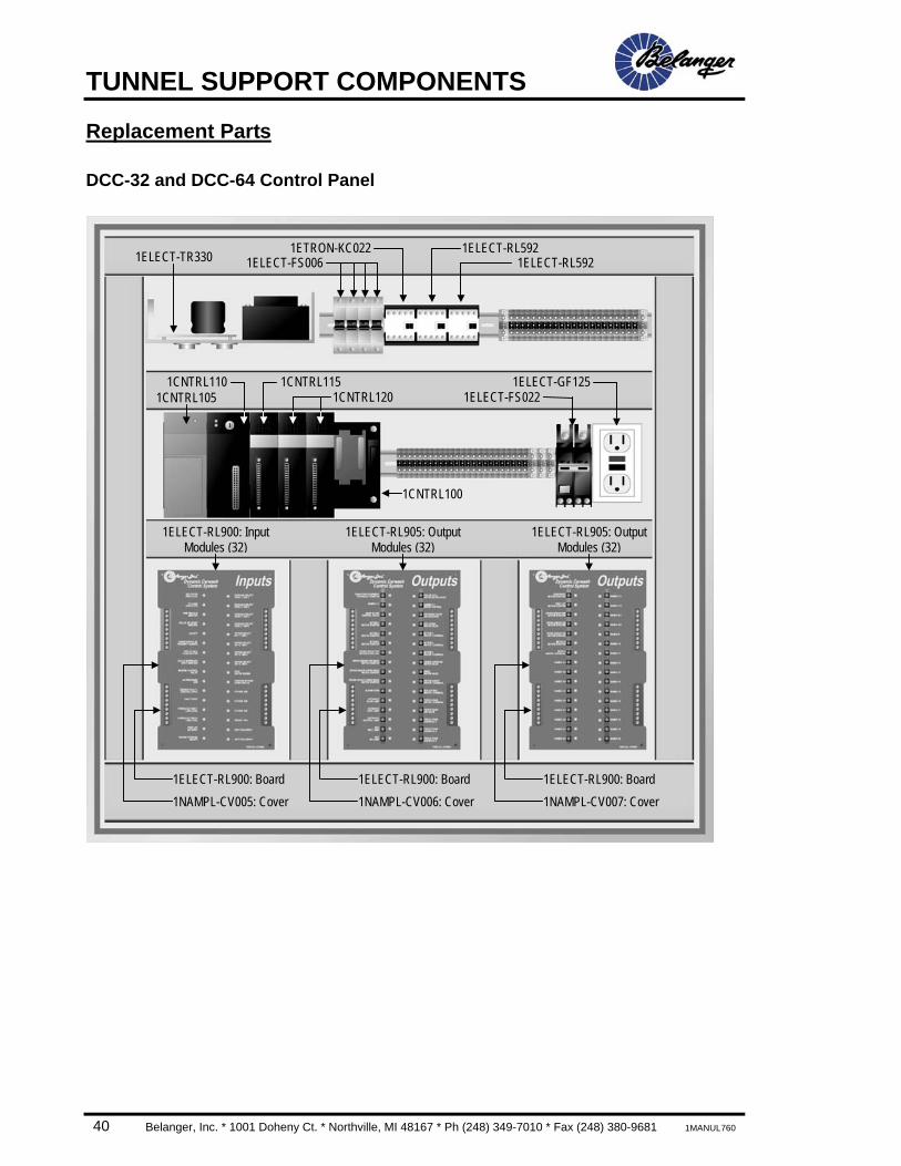
DCC-32 and DCC-64 Control Panel
1ELECT-TR330 1ELECT-FS0061ETRON-KC022 1ELECT-RL592
1ELECT-RL592
1ELECT-GF1251CNTRL105 1ELECT-FS022
1CNTRL110 1CNTRL115 1CNTRL120
1CNTRL100
1ELECT-RL900: Board 1NAMPL-CV005: Cover
1ELECT-RL900: Board 1NAMPL-CV006: Cover
1ELECT-RL900: Board 1NAMPL-CV007: Cover
1ELECT-RL900: Input Modules (32)
1ELECT-RL905: Output Modules (32)
1ELECT-RL905: Output Modules (32)
TUNNEL SUPPORT COMPONENTS
1MANUL760 Belanger, Inc. * 1001 Doheny Ct. * Northville, MI 48167 * Ph (248) 349-7010 * Fax (248) 380-9681 41
Installation
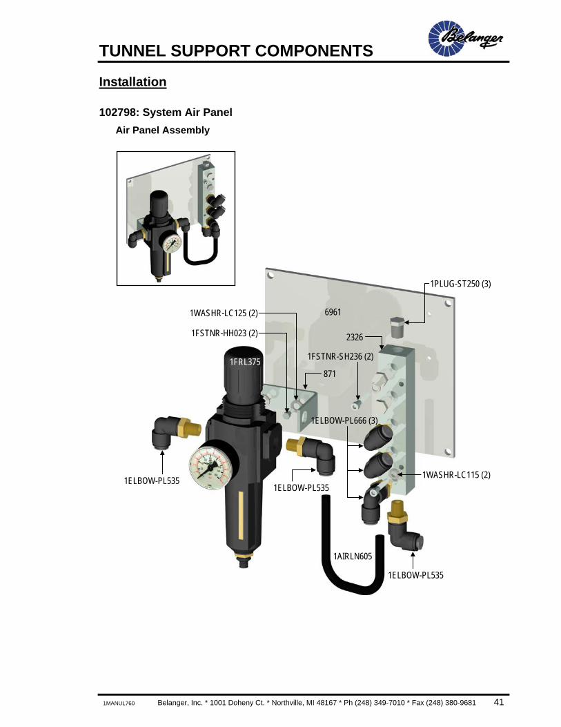
102798: System Air Panel Air Panel Assembly
6961
1PLUG-ST250 (3)
1ELBOW-PL535
1FRL375
1ELBOW-PL535
1ELBOW-PL535
1FSTNR-HH023 (2)
1WASHR-LC125 (2)
1ELBOW-PL666 (3)
1AIRLN605
2326
871
1FSTNR-SH236 (2)
1WASHR-LC115 (2)
TUNNEL SUPPORT COMPONENTS
42 Belanger, Inc. * 1001 Doheny Ct. * Northville, MI 48167 * Ph (248) 349-7010 * Fax (248) 380-9681 1MANUL760
Installation
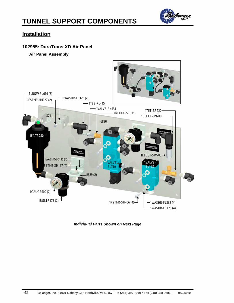
102955: DuraTrans XD Air Panel Air Panel Assembly
Individual Parts Shown on Next Page
1FSTNR-HH027 (2)
1FILTR780
6890
1VALVE-EL710
1GAUGE500 (2)
1TEE-PL415
2529 (2)
1FSTNR-SH177 (4)
1WASHR-LC115 (4)
1TEE-BR920
1RGLTR175 (2) 1WASHR-FL332 (4)
1ELECT-DN780
1VALVE-EL152
1WASHR-LC125 (4) 1FSTNR-SH406 (4)
1WASHR-LC125 (2)
871
1ELECT-SW780
1VALVE-PN531 1REDUC-ST111
1ELBOW-PL666 (8)

TUNNEL SUPPORT COMPONENTS
1MANUL760 Belanger, Inc. * 1001 Doheny Ct. * Northville, MI 48167 * Ph (248) 349-7010 * Fax (248) 380-9681 43
Installation
102955: DuraTrans XD Air Panel Air Panel Parts
2529 1FILTR780 1GAUGE500 1RGLTR175 1TEE-PL415 1VALVE-EL710
1TEE-BR920 1ELECT-SW780 1ELECT-DN780 1VALVE-PN531 1REDUC-ST111 1VALVE-PN152
1DECAL-XD001 1DECAL-XD002 1DECAL-XD010
TUNNEL SUPPORT COMPONENTS
44 Belanger, Inc. * 1001 Doheny Ct. * Northville, MI 48167 * Ph (248) 349-7010 * Fax (248) 380-9681 1MANUL760
Installation
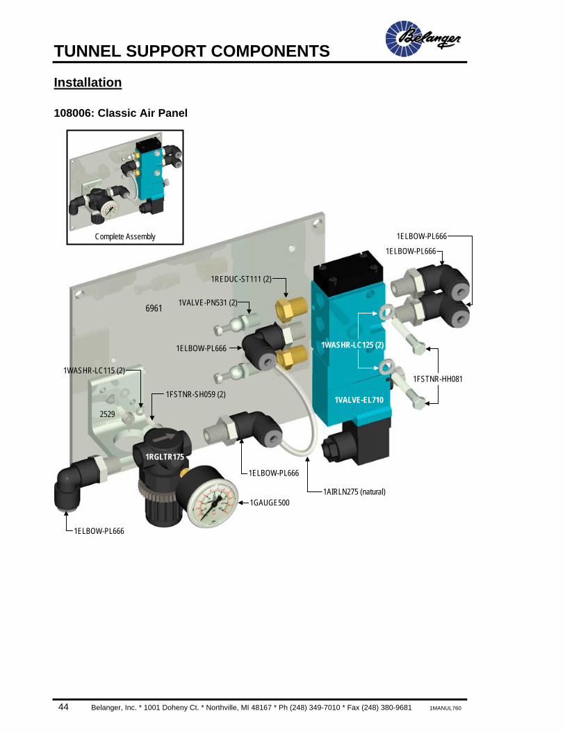
108006: Classic Air Panel
6961
Complete Assembly
1RGLTR175
1VALVE-EL710
1ELBOW-PL666
1FSTNR-HH081
1ELBOW-PL666
1WASHR-LC115 (2)
1FSTNR-SH059 (2)
2529
1GAUGE500
1ELBOW-PL666
1ELBOW-PL666
1WASHR-LC125 (2)
1ELBOW-PL666
1AIRLN275 (natural)
1VALVE-PN531 (2)
1REDUC-ST111 (2)
TUNNEL SUPPORT COMPONENTS
1MANUL760 Belanger, Inc. * 1001 Doheny Ct. * Northville, MI 48167 * Ph (248) 349-7010 * Fax (248) 380-9681 45
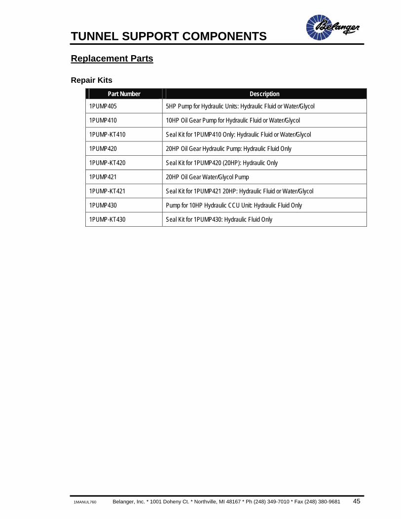
Replacement Parts
Repair Kits Part Number Description
1PUMP405 5HP Pump for Hydraulic Units: Hydraulic Fluid or Water/Glycol
1PUMP410 10HP Oil Gear Pump for Hydraulic Fluid or Water/Glycol
1PUMP-KT410 Seal Kit for 1PUMP410 Only: Hydraulic Fluid or Water/Glycol
1PUMP420 20HP Oil Gear Hydraulic Pump: Hydraulic Fluid Only
1PUMP-KT420 Seal Kit for 1PUMP420 (20HP): Hydraulic Only
1PUMP421 20HP Oil Gear Water/Glycol Pump
1PUMP-KT421 Seal Kit for 1PUMP421 20HP: Hydraulic Fluid or Water/Glycol
1PUMP430 Pump for 10HP Hydraulic CCU Unit: Hydraulic Fluid Only
1PUMP-KT430 Seal Kit for 1PUMP430: Hydraulic Fluid Only

TUNNEL SUPPORT COMPONENTS
46 Belanger, Inc. * 1001 Doheny Ct. * Northville, MI 48167 * Ph (248) 349-7010 * Fax (248) 380-9681 1MANUL760
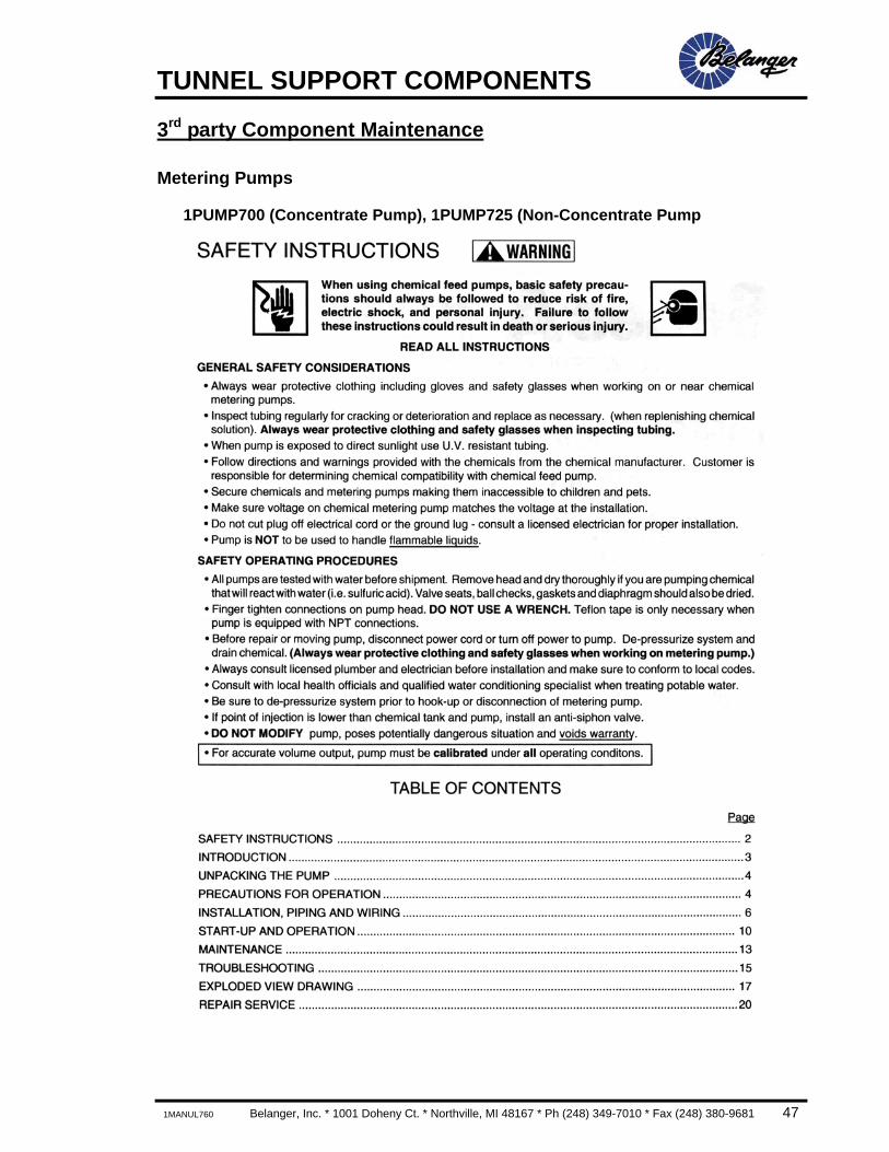
3rd party Component Maintenance
Metering Pumps
1PUMP700 (Concentrate Pump), 1PUMP725 (Non-Concentrate Pump
TUNNEL SUPPORT COMPONENTS
1MANUL760 Belanger, Inc. * 1001 Doheny Ct. * Northville, MI 48167 * Ph (248) 349-7010 * Fax (248) 380-9681 47
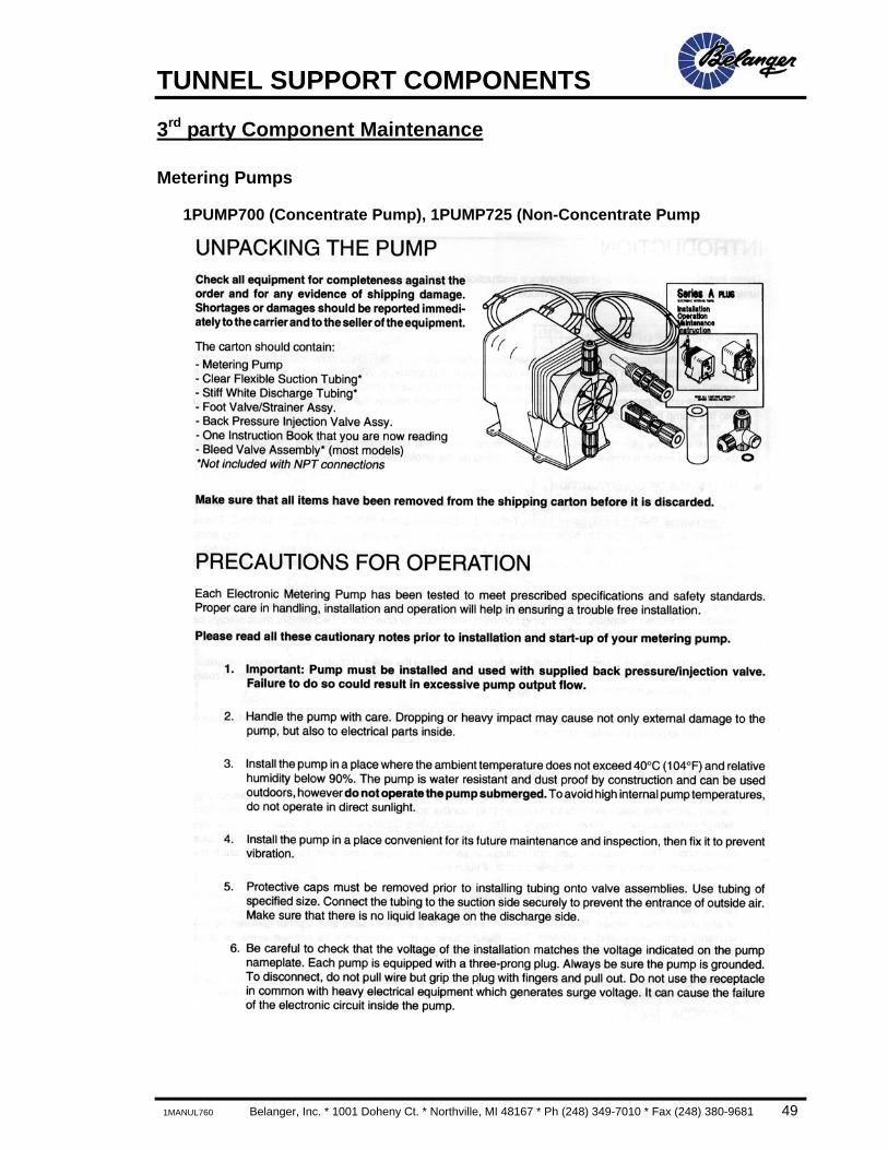
3rd party Component Maintenance
Metering Pumps
1PUMP700 (Concentrate Pump), 1PUMP725 (Non-Concentrate Pump

TUNNEL SUPPORT COMPONENTS
48 Belanger, Inc. * 1001 Doheny Ct. * Northville, MI 48167 * Ph (248) 349-7010 * Fax (248) 380-9681 1MANUL760
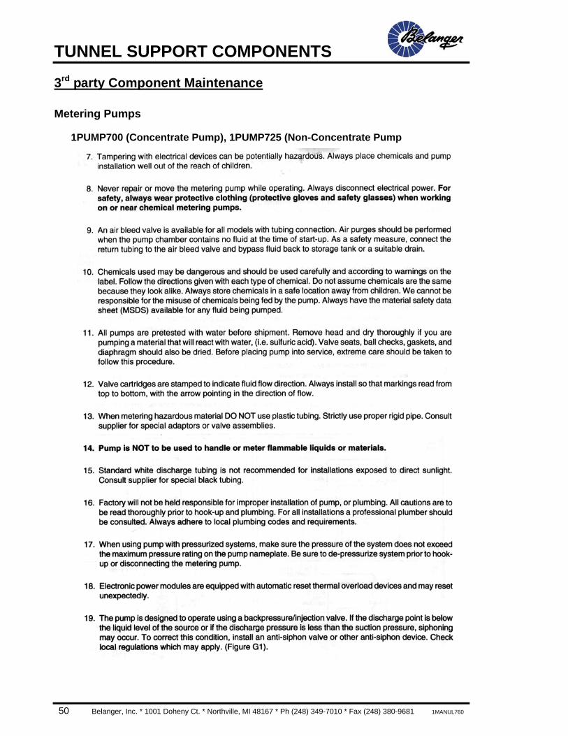
3rd party Component Maintenance
Metering Pumps
1PUMP700 (Concentrate Pump), 1PUMP725 (Non-Concentrate Pump
TUNNEL SUPPORT COMPONENTS
1MANUL760 Belanger, Inc. * 1001 Doheny Ct. * Northville, MI 48167 * Ph (248) 349-7010 * Fax (248) 380-9681 49
3rd party Component Maintenance
Metering Pumps
1PUMP700 (Concentrate Pump), 1PUMP725 (Non-Concentrate Pump
TUNNEL SUPPORT COMPONENTS
50 Belanger, Inc. * 1001 Doheny Ct. * Northville, MI 48167 * Ph (248) 349-7010 * Fax (248) 380-9681 1MANUL760
3rd party Component Maintenance
Metering Pumps
1PUMP700 (Concentrate Pump), 1PUMP725 (Non-Concentrate Pump
TUNNEL SUPPORT COMPONENTS
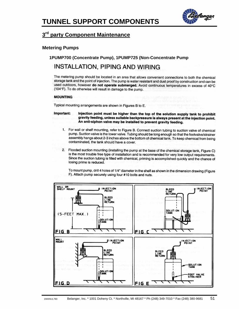
1MANUL760 Belanger, Inc. * 1001 Doheny Ct. * Northville, MI 48167 * Ph (248) 349-7010 * Fax (248) 380-9681 51
3rd party Component Maintenance
Metering Pumps
1PUMP700 (Concentrate Pump), 1PUMP725 (Non-Concentrate Pump
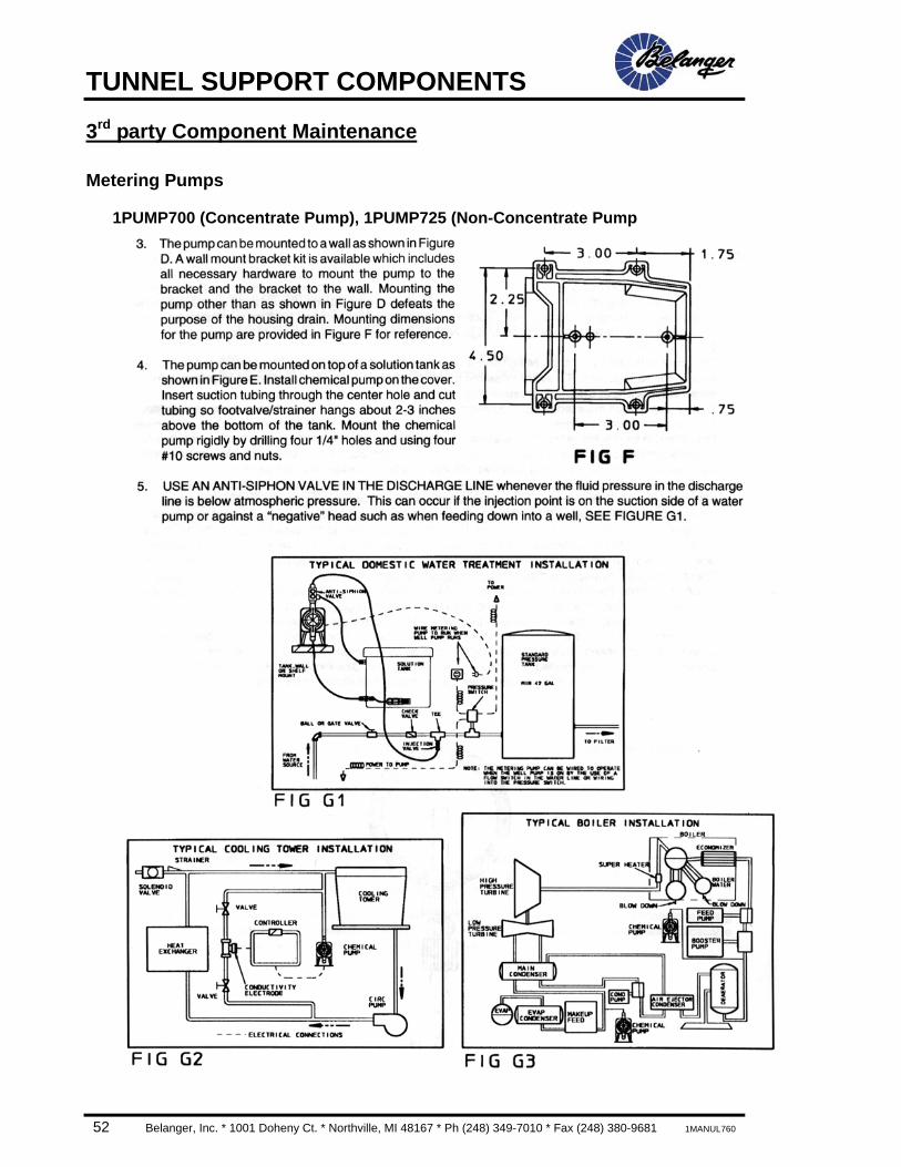
TUNNEL SUPPORT COMPONENTS
52 Belanger, Inc. * 1001 Doheny Ct. * Northville, MI 48167 * Ph (248) 349-7010 * Fax (248) 380-9681 1MANUL760
3rd party Component Maintenance
Metering Pumps
1PUMP700 (Concentrate Pump), 1PUMP725 (Non-Concentrate Pump
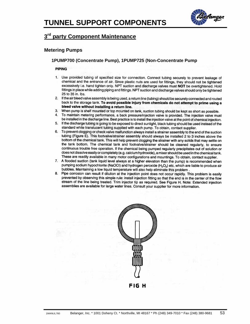
TUNNEL SUPPORT COMPONENTS
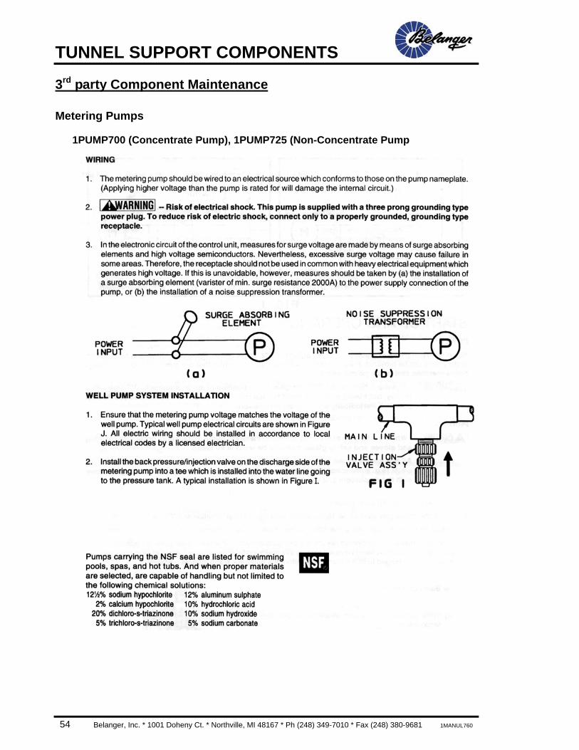
1MANUL760 Belanger, Inc. * 1001 Doheny Ct. * Northville, MI 48167 * Ph (248) 349-7010 * Fax (248) 380-9681 53
3rd party Component Maintenance
Metering Pumps
1PUMP700 (Concentrate Pump), 1PUMP725 (Non-Concentrate Pump
TUNNEL SUPPORT COMPONENTS
54 Belanger, Inc. * 1001 Doheny Ct. * Northville, MI 48167 * Ph (248) 349-7010 * Fax (248) 380-9681 1MANUL760
3rd party Component Maintenance
Metering Pumps
1PUMP700 (Concentrate Pump), 1PUMP725 (Non-Concentrate Pump
TUNNEL SUPPORT COMPONENTS
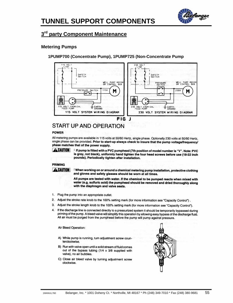
1MANUL760 Belanger, Inc. * 1001 Doheny Ct. * Northville, MI 48167 * Ph (248) 349-7010 * Fax (248) 380-9681 55
3rd party Component Maintenance
Metering Pumps
1PUMP700 (Concentrate Pump), 1PUMP725 (Non-Concentrate Pump
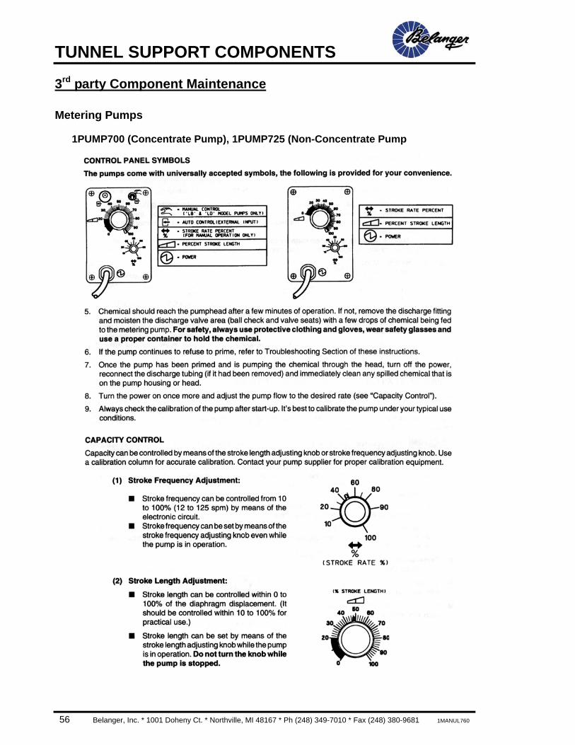
TUNNEL SUPPORT COMPONENTS
56 Belanger, Inc. * 1001 Doheny Ct. * Northville, MI 48167 * Ph (248) 349-7010 * Fax (248) 380-9681 1MANUL760
3rd party Component Maintenance
Metering Pumps
1PUMP700 (Concentrate Pump), 1PUMP725 (Non-Concentrate Pump

TUNNEL SUPPORT COMPONENTS
1MANUL760 Belanger, Inc. * 1001 Doheny Ct. * Northville, MI 48167 * Ph (248) 349-7010 * Fax (248) 380-9681 57
3rd party Component Maintenance
Metering Pumps
1PUMP700 (Concentrate Pump), 1PUMP725 (Non-Concentrate Pump

TUNNEL SUPPORT COMPONENTS
58 Belanger, Inc. * 1001 Doheny Ct. * Northville, MI 48167 * Ph (248) 349-7010 * Fax (248) 380-9681 1MANUL760
3rd party Component Maintenance
Metering Pumps
1PUMP700 (Concentrate Pump), 1PUMP725 (Non-Concentrate Pump
TUNNEL SUPPORT COMPONENTS
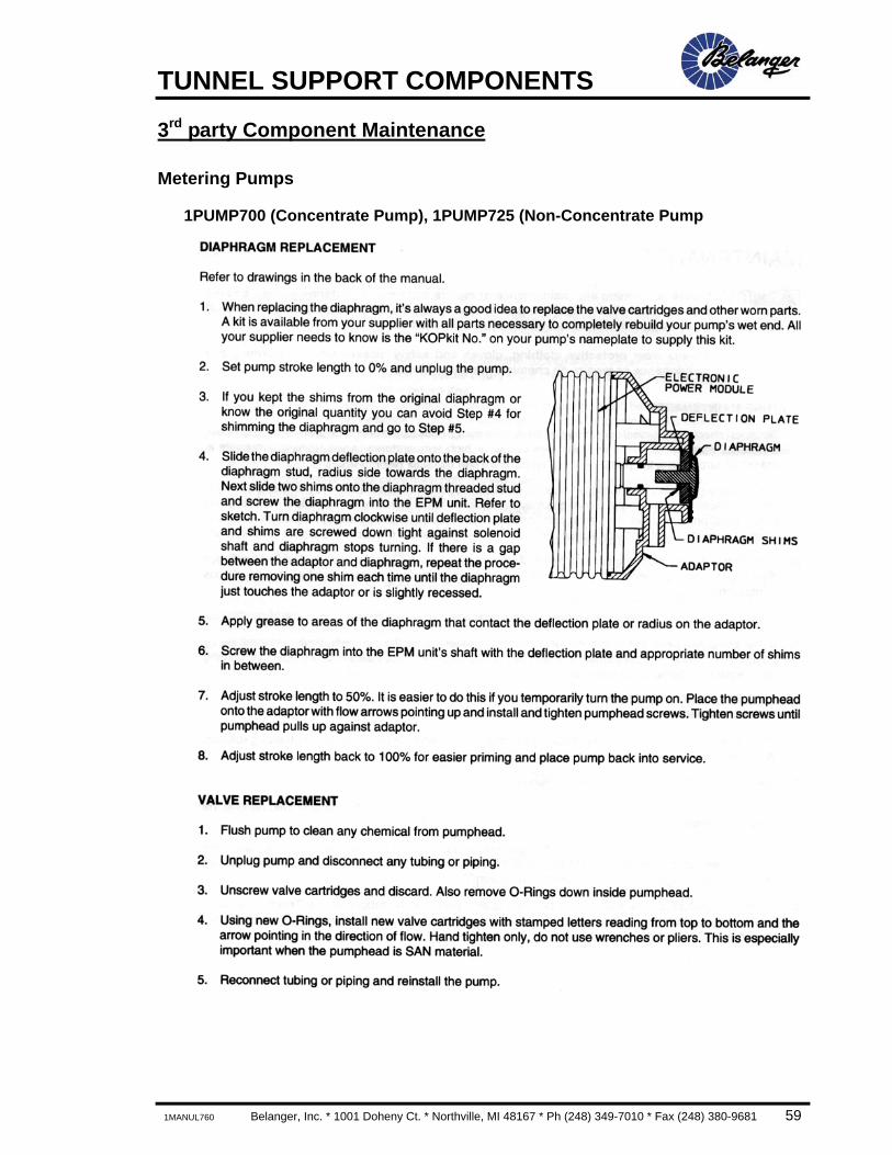
1MANUL760 Belanger, Inc. * 1001 Doheny Ct. * Northville, MI 48167 * Ph (248) 349-7010 * Fax (248) 380-9681 59
3rd party Component Maintenance
Metering Pumps
1PUMP700 (Concentrate Pump), 1PUMP725 (Non-Concentrate Pump
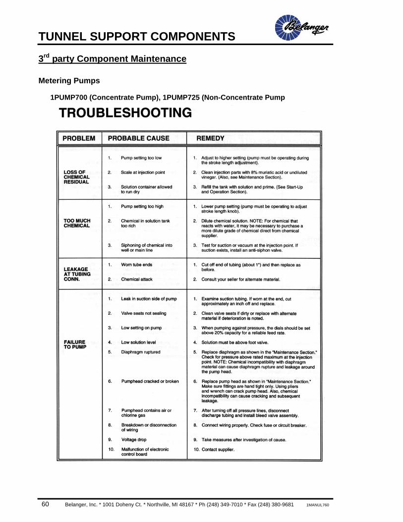
TUNNEL SUPPORT COMPONENTS
60 Belanger, Inc. * 1001 Doheny Ct. * Northville, MI 48167 * Ph (248) 349-7010 * Fax (248) 380-9681 1MANUL760
3rd party Component Maintenance
Metering Pumps
1PUMP700 (Concentrate Pump), 1PUMP725 (Non-Concentrate Pump
TUNNEL SUPPORT COMPONENTS
1MANUL760 Belanger, Inc. * 1001 Doheny Ct. * Northville, MI 48167 * Ph (248) 349-7010 * Fax (248) 380-9681 61
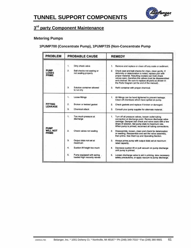
3rd party Component Maintenance
Metering Pumps
1PUMP700 (Concentrate Pump), 1PUMP725 (Non-Concentrate Pump

TUNNEL SUPPORT COMPONENTS
62 Belanger, Inc. * 1001 Doheny Ct. * Northville, MI 48167 * Ph (248) 349-7010 * Fax (248) 380-9681 1MANUL760
3rd party Component Maintenance
Metering Pumps
1PUMP700 (Concentrate Pump), 1PUMP725 (Non-Concentrate Pump

TUNNEL SUPPORT COMPONENTS
1MANUL760 Belanger, Inc. * 1001 Doheny Ct. * Northville, MI 48167 * Ph (248) 349-7010 * Fax (248) 380-9681 63
3rd party Component Maintenance
Metering Pumps
1PUMP700 (Concentrate Pump), 1PUMP725 (Non-Concentrate Pump
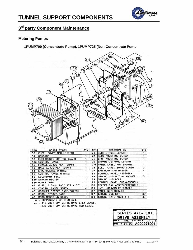
TUNNEL SUPPORT COMPONENTS
64 Belanger, Inc. * 1001 Doheny Ct. * Northville, MI 48167 * Ph (248) 349-7010 * Fax (248) 380-9681 1MANUL760
3rd party Component Maintenance
Metering Pumps
1PUMP700 (Concentrate Pump), 1PUMP725 (Non-Concentrate Pump
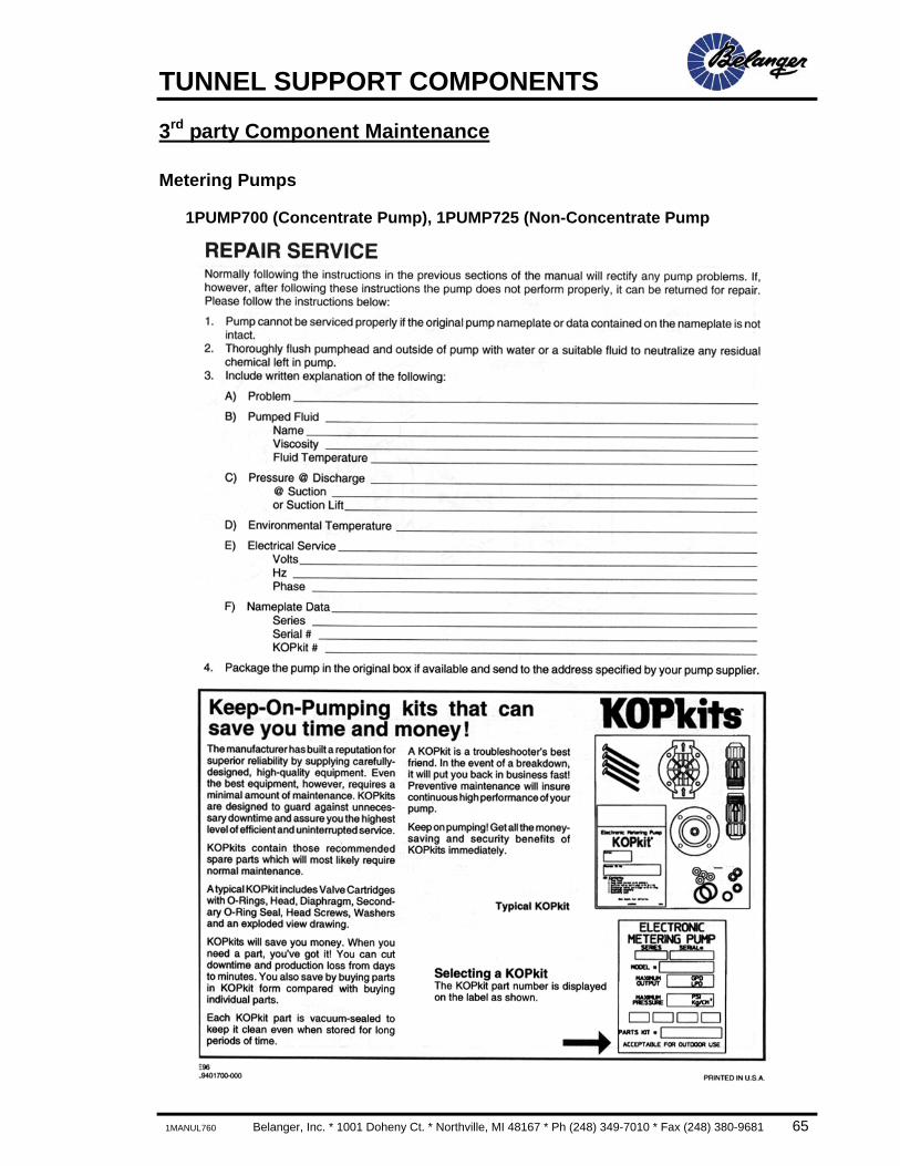
TUNNEL SUPPORT COMPONENTS
1MANUL760 Belanger, Inc. * 1001 Doheny Ct. * Northville, MI 48167 * Ph (248) 349-7010 * Fax (248) 380-9681 65
3rd party Component Maintenance
Metering Pumps
1PUMP700 (Concentrate Pump), 1PUMP725 (Non-Concentrate Pump


Tunnel Carwash Support Components 1MANUL762
Belanger, Inc. * P.O. Box 5470 * Northville, MI 48167-5470 Customer Service Phone (248) 347-4700 * Fax (248) 380-9681