tunnel construction technology for soft...
TRANSCRIPT
Tunnel Construction Technology
for Soft Ground
Prof. Mitsutaka Sugimoto
Nagaoka University of Technology
Japan
EJEC/AIT seminar, 14, June, 2016

2
CONTENTS
I. Introduction of tunnelling method
II. Shield tunnelling method
III. Tunnelling in Bangkok

3
I. Introduction of tunnelling method
1. TUNNELLING METHODS
2. HISTORY OF TECHNOLOGY

4
1. TUNNELLING METHODS
(1) Mountain tunnelling method (NATM)
Drilling Mucking Shotcrete Rock bolts Concrete lining

5
(2) Shield tunnelling method

6
(3) Cut & cover method

7
(4) Immersed tunnelling method
Survey target
GravelGasket

8

9
SummaryTunnelling m ethod
C ondition
N A TM Shield T . C ut & cover
T .
Im m ersed T .
D esign stage
C lassification:
-soil
-soft rock
-hard rock
△
◯
◯
◯
△
×
◯
△
×
◯
△
×
G round w ater:
-under ground w ater
-over ground w ater
△
◯
◯
◯
△
◯
◯
-
G round
condition
Self-stability of face:
-unexpected
-expected
×
◯
◯
◯
◯
◯
-
-
Structure Location:
-near ground surface
-shallow
-deep
×
△
◯
△
◯
◯
◯
△
×
◯
×
×
C onstruction stage
Excavation:
-general
-other
blast
rotary cutter
(TBM )
excavator
rotary cutter
excavator
m anual
excavator
dredging
rotary cutter
C onstruction
m ethod
Support shotcrete
rock bolt
segm ent
EC L
box culvert steel box
concrete box
Environm ent Influence to traffic
N oise/v ibration
◯
×
◯
◯
△
△
×
△

14
II. Shield tunnelling method
1. Technology
2. Advanced technology
3. Recent topics

15
1. TECHNOLOGY
TBM
Segment
Interaction between tunnel & ground

16
1.1 TBM
Classification
EP
BS
Partially open shield
Shield typeOpen shield TBM
Dual mode
Slu
rry sh
ield

24
Closed shield vs. Open shield
Item C losed shield O pen shield
A pplicable ground
condition
C an cope w ith a w ide range of
ground conditions, i.e., from soft
clay, loose sand, gravel to soft
rock.
In principle, the face m ust be
stable.
Face stability R elatively easy, since the shield
system have the function to
stabilize the face.
R elatively difficult.
E fficiency of
construction
A dvances in m echanization have
resulted in increasing efficiency
and labor saving. Excavation
rate is faster.
It is difficult to increase
efficiency or save labor, since it
depends on labor. Excavation
rate is slow er.
G round stabilization
w orks
In principle, no auxiliary w orks
are required for tunnelling.
A ground stabilization w ork is
essential to secure the face
stability.
C onstruction cost The unit cost per volum e is about the sam e, depending on the ground
condition, som etim es cheaper w ith closed shield .
T roubles in construction Few er troubles M any troubles

25
Slurry shield vs. EPBS
Item Slurry shield Earth pressure balanced shield
A pplicable ground
condition
M ainly sandy soils. A lso can
cope w ith clay and sand-gravel
layers. Particularly excellent
against high ground w ater
pressures.
M ainly clayey soils. U sing m ud
pressure shield, can cope w ith
sandy soils and sand- gravel.
Particularly excellent for handling
larger gravel size. M any
construction records.
A pplicable diam eter U sed for m edium -and sm all
diam eter tunnels and som e large-
diam eter tunnels.
M any construction records for
m edium - and sm all-diam eter
tunnels.
S ize of facilities S lurry treatm ent plant is
necessary, then larger space is
required.
R elatively sm all.
C utter torque Sm all Larger
C utter driving m ode E lectric pow er increasingly H ydraulic pow er in m any cases

26
Flow of shield selection
1 . design condition (1) shapes
(2) dim ension
(3) length
(4) tunnel depth
(5) curve radius
(6) gradient
(7) lining m ethod
2 . ground condition (1) com position and variation of ground
(2) soil condition
(3) ground w ater level
(4) pore w ater pressure
(1) face stability
(2) perm eability
(3) ventage ratio (air perm eability)
Supplem ental m ethod is necessary or not
3 . environm ental condition (1) river, sea lake
(2) underground structure
(3) structure at ground surface
(4) neighboring structure
(5) road, traffic
(6) condition of the w ork area
(7) pow er supply
4 . construction capability (1) construction schedule
(2) safety
(3) w orking condition
(4) transportation condition
5 . econom ics (cost saving)
6 . selection of shield type

27
1.2 Lining
Segment
RC segment Plate type Steel segment
RC segment Box type Ductile segment

28
Joint
M aterial Section configuration Joint type
Reinforced concrete Plate type Straight bolt joint type
Steel Curved bolt joint type
D uctile cast iron Box type Pin joint type
Com posite H inge type

29
Classification of structure model
(1) Lining model1) Bender beam without the reduction of EI.2) Bender beam with the reduction of EI.3) Multi-hinge without rotation spring and shear spring.4) Multi-hinge with rotation spring at hinge.5) Multi-hinge with rotation spring at hinge and shear spring
between neighbor ring.
Design model

30
(2) Ground model
1) Continuous medium 2) Spring 4) Nothing
3) No-tension spring
(Winckler's ground model)
Classification of load model
(3) Resistance earth pressure
1) calculated by displacement. 2) given.
(4) Earth pressure
1) sV 2) sH + sV

31
Classification of boundary
(5) Boundary condition between ground and lining
1) Slide in tangential direction
a. is allowed b. is not allowed
2) Initial displacement of ground
a. is considered.
b. is not considered.

32
Design loads (1)C ategory D esign load C om m ent
Earth pressure 1 . V ertical earth pressure at crow n , sVU
1) Soft clay or
stiff clay w ith H /D <1 or
sand w ith H /D <1
sVU = (effective) overburden load
2) S tiff clay w ith H /D >3 or
sand w ith H /D >3
sVU = Terzaghi's loosening (effective) earth pressure
2 . H orizontal earth pressure , sH
sH = sV
sV = sVU + h
:lateral earth pressure ratio
:(subm erged) density of ground
h :depth from crow n
H :overburden depth
D :d iam eter of tunnel
H ydraulic pressure 1 . Sandy ground
C onsider effective earth pressure and hydraulic pressure
separately.
2 . C layey ground
C onsider total earth pressure, w hich m eans the use of density (not
subm erged density) in the calculation of earth pressure.
R esistance earth pressure 1 . V ertical resistance earth pressure
A ssum e vertical resistance earth pressure at the bottom of tunnel
so as that vertical force has balanced.
2 . H orizontal resistance earth pressure
This pressure is generated due to the deform ation of lin ing.
O verburden load This load is generated due to the structures on the ground surface.
M ain load
Self-w eight The w eight of lin ing
33
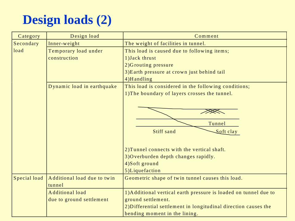
Design loads (2)C ategory D esign load C om m ent
Inner-w eight The w eight of facilities in tunnel.
Tem porary load under
construction
This load is caused due to follow ing item s;
1)Jack thrust
2)G routing pressure
3)Earth pressure at c rown just behind tail
4)H andling
Secondary
load
D ynam ic load in earthquake This load is considered in the follow ing conditions;
1)The boundary of layers crosses the tunnel.
2)Tunnel connects w ith the vertical shaft.
3)O verburden depth changes rapidly.
4)Soft ground
5)Liquefaction
A dditional load due to tw in
tunnel
G eom etric shape of tw in tunnel causes this load. Special load
A dditional load
due to ground settlem ent
1)A dditional vertical earth pressure is loaded on tunnel due to
ground settlem ent.
2)D ifferential settlem ent in longitudinal direction causes the
bending m om ent in the lining.
Stiff sand Soft clay
Tunnel

34
Design load & models
Pe :vertical earth pressure : lateral earth pressure ratiog : self weight of segment per unit length
resistance earth pressurepg : due to self weight of segmentqH : in horizontal directionqV : vertical directionqr : radial direction

35
Moment and axial force on each analysis model

36
Flow of of segment designSTA RT
(1) decide segm ent type, design load
(2) decide the segm ent dim ension (thickness, reinforced steel)
(3) decide the physical properties ( ,. spring constant etc.)
(4) calculate sectional force
(5) calculate stress
(6) stress < allow able stress ?
(7) design the detail of segm ent
(8) check ?
EN D
37
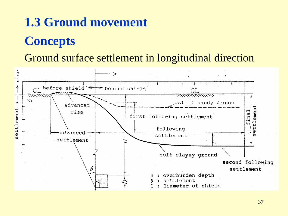
1.3 Ground movement
Concepts
Ground surface settlement in longitudinal direction

38
Ground surface settlement in transverse direction

39
Three dimensional displacement around face
(a) Clay (b) Sand

40
Measurements examples
1979 Mexico 1985 Mexico

42
Analysis method
(1) Empirical method: error function form

43
(2) Conventional 2D FEM analysis
E
α
a: Stress release ratio

44
(a) t=t0
Jack thrust
Ground
Shield
Exca. E
(b) t=t0+dt
Ground
Shield
Exca. E
(c) t=t0+dt
Ground
Shield
Exca. E
Excavation elements & remesh of ground (Akagi & Komiya)
(3) 3DFEM analysis: Akagi – Komiya model

46
Vertical Disp. at 1.0m above crown (Akagi & Komiya)
0.03514 day
0.21924 day
0.40494 day
0.52266 day
1.12640 day
1.64357 day
Measurement point

47
2. ADVANCED TECHNOLOGY
Technology for
safety,
high quality,
economy,
high speed.
2.1 TBMSharp curve
Articulated shield

48
Variation of cross section
Rectangular cross section
Swing drum type Fixed drum type
Box type DPLEX

49
Double circular cross section
Multi face shield
DOT shield

50
3 circular cross section

51
H & V shield

52
Wing shield
Excavation mechanism

53
DPLEX shield

55
Docking / Branching
Mechanical docking

56
Branching

57
2.2 Segment
Saving work
Pin coupler + Mortise & tenon joint Wedge joint
Pin coupler + Bolt joint

59
3. RECENT TOPICS
3.1 TBMLong distance
Wear resistance (cutter bit, seal)
High speed
Continuous excavation
Prediction & control: theoretical model
Kinematic shield model
Docking / Branching
60
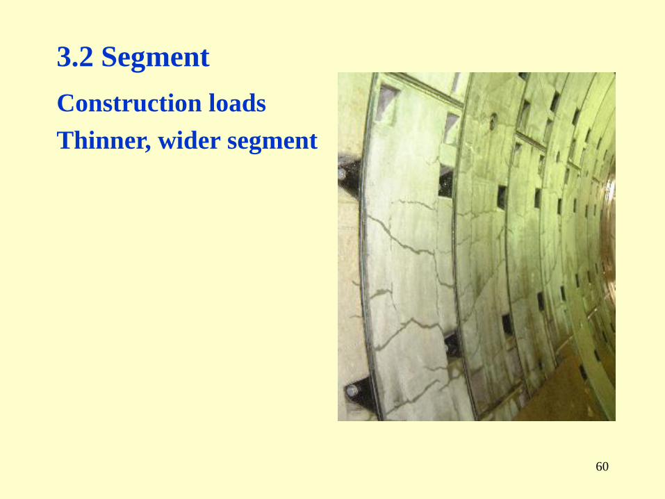
3.2 Segment
Construction loads
Thinner, wider segment

62
Corrosion
Maintenance
Waterproof sheet

63
Renewal
Ex. Renewal of cut & cover tunnel
Advance direction

64
Ex. Renewal of shield tunnel

65
3.3 Ground movement
Neighboring construction
Analysis method
Deep tunnel
Design method (Design loads)

66
III. Tunnelling in Bangkok
1. HISTORY OF SHIELD TUNNELLING IN
BKK
2. PROBLEM STATEMENTS
3. COUNTERMEASURES
(The Shoho Magazine, 1996.4, JCC, BKK)

67
1. HISTORY OF SHIELD TUNNELLING IN BKK
Year Use Length
(km)
Dia.
(m)
Soil Depth
(m)
TBM
1970 Flood
discharge
1.8 3.3 Soft Clay 5~8 Blind
1975~1979 Water
supply
24.5 2.0~3.4 Stiff clay,
Under river
17~20 Open (Mechanical)
-> Slurry
1981~1983 Water
supply
7.1 2.0~2.5 Stiff clay 17~20 Open
(Semi mechanical)
1986~1988 Water
supply
34.0 2.0~3.2 Soft clay 0~9 C&C, Pipe jacking
1990~1991 Water
supply
2.2 2.0 Stiff clay 18 Open
(Semi mechanical)
1994~ Sewage 9.0 2.5~3.2 Soft/Stiff
clay
10~18 EPBS
1995~ Water
supply
10.5 2.0 Stiff clay 16~18 EPBS
Noppadol Phienwej, “Tunnel lining and cut-and-cover excavation in Bangkok soils”,
Seminar on urban and traffic engineering and geotechnical engineering on delta areas, 1996. 3.

68
Master plan of
mass rapid transit
in BKK
“Master plan Bangkok mass rapid transit”,
Executive summary report, 1994.7.
(in Thai language) Area to construct MRT by subway.Area to construct MRT by subway expectedly.

69
2. PROBLEM STATEMENTS
(1) Soft soil, ground water
Geological profile (W – E)
ESCAP, “Geological information for planning in Bangkok, Thailand”,
Geology and urban development-Atlas of urban geology, ESCAP,
Vol. 1, 24-60, 1988.
Softclay
Stiffclay Sand
SandyclayLaterite

(2) Ground subsidence
Ground subsidence
Around 1996, the subsidence
speed is around 1 ~ 3
cm/year1).
TP contour (m)
Subsidence V.(cm/y)
ESCAP, “Geological information for
planning in Bangkok , Thailand”,
Geology and urban development-Atlas of
urban geology, ESCAP, Vol. 1, 24-60,
1988.
1) Yordphol Tanaboriboon, “Demand
management and traffic crisis in Bangkok”,
Seminar on urban and traffic engineering
and geotechnical engineering on delta areas,
1996. 3.

71
(3) Flood
Depth of water in BKK
at 1983 flood
(by JICA, 1984)
(cm)
ESCAP, “Geological information for
planning in Bangkok , Thailand”,
Geology and urban development-Atlas
of urban geology, ESCAP, Vol. 1, 24-60,
1988.
Max depth of water = 1.1m
In 1995 flood, damage to
BKK is less than that of
1983 flood.

72
3. COUNTERMEASURES (Tunnel)Problems Counter measures
Soft ground, ground water
Construction Surface settlement
Face stability
TBM control
Select layers
Adopt a closed type shield
Ex. Protection wall
Operation Leakage Ensure watertight
Set discharging pumps
Ground subsidence
Operation Unequal subsidence Restrict pumping up groundwater
Select layers
Set the flexible connection between station
& tunnel at design
Adjust rail alignment
Flood
Construction
Operation
Flooding Consider the influence of flood on station
& shaft at design
Set discharging pumps

73
3. COUNTERMEASURES
(Environment)
Problems Counter measures
Traffic disturbance
Construction Station
Vertical shaft
Adopt a trenchless method
Use a open space around road
Influence on neighboring structures
Construction Structure Adopt a countermeasures

74
Thank you for your kind attention !!

75

76
3. CONSTRUCTION RECORDS IN JAPAN
History
Railway
Len
gth
(k
m)
Road
Year

77
1. SELECTION OF
TUNNELLING METHODSItem NATM Shield Cut &
coverSoil type
SoilSoft rockHard rock
Ground water levelunderover
Ground
conditon
Face stabilizationunexpectedexpected
Location Depthnear ground surfaceshallowdeep

78
Vertical Disp. (Akagi & Komiya)
2
-8
-6
-4
-2
0
0 0.5 1 1.5 2
Time (day)
Ver
tica
l dis
p. (m
m)
1m above crown
Measured
Calculated