tunnel liner plate - asset international · tunnel liner plate is available in a wide variety of...
TRANSCRIPT
TUNNEL LINER PLATE

COVER PHOTO: Custom shape designed for relining a railroad masonry culvert.
Pipe Arch Shape used in relining an existing masonry culvert under a railroad.
FEATURES & BENEFITS OFASSET TUNNEL LINER PLATE
SAFEECONOMICAL
VERSATILE
SIMPLE
EASY TO HANDLE
READILY AVAILABLE
All underground work can be undertaken from within the assembled shell.
Strong corrugated steel plates provide maximum strength at the lowest weight. Two-flange design provides optimum stiffness.
Many shapes are available; liner plate can be installed horizontally for tunnelsand relines, or vertically for shafts and caissons.
Excavate – muck out – assemble liner – grout. No complex tunnelling equipment is required.
With only two basic parts (plates and fasteners), no special skills are requiredfor assembly. All plates can be carried by a single person if required.
Structures are made to order in our central factory and shipped to the customer’s project location.
Applications:• Soft ground tunnelling
• Relining existing structures
• Vertical shaft liners
• Caissons
• Rockfall protection (mining applications)
Digging at the tunnel face using a shield.
2

1.6 2.0 2.8
3
GeneralASSET steel Tunnel Liner Plate is a corrugated steel, two-flange sectional lining system designed for use primarily insoft-ground tunnelling. Tunnel Liner Plate is available in a wide variety of shapes and sizes, from as small as 1.3 mdiameter to a maximum 8 m diameter.
Product Description
Tunnelling vs Cut and CoverTunnelling is most often used whenthe surface above the works cannotbe open cut. This may be due to thefollowing: • traffic above• existing buildings or structures • space or clearance restrictions
Typical tunnelling applications wouldinclude the installation of drainage orutilities in:• urban environments • under highways • under railways
Additional uses of Tunnel Linerinclude:• caissons and shafts
(vertical tunnelling) • pipe relines, where access is
available only from inside the liner• pipe relines with vertical or
horizontal changes in alignment(sharp turns)
AssemblyTunnel Liner is assembled completelyfrom within the progressing structure. This is possible due to thebolted flanged circumferential seamsand the use of retaining clips andbolts at the longitudinal seams. Allcomponents can be safely hand-carried into the assembly area.
Tunnel Liner Plate is one of the safestproducts available for soft-groundtunnelling due to:
a. Full assembly from inside the completed portion of the structure
b. Small plates (500 mm wide) allowminimum unsupported excavation.In poor soils this can be as little asthe excavation required to install a single plate. For greater efficiency,excavation should permit installation of a complete ring.
c. Minimum over-excavation isrequired: As all connections aremade from within the finishedportion of the structure, the excavation needs to be only sufficient to allow assembly of theplates. This reduces risk of impacton the structure due to settlementabove.
d. Bolt torque recommended is 135to 170 N.m.
Completing the InstallationAfter installation in the excavatedtunnel or shaft line, the Tunnel LinerPlate is grouted into place. Groutingis normally undertaken at the end ofevery shift. Factory-installed groutports allow work to be completedfrom within the structure.
Two components
Finish
Shapes
Plate size
Design method
Curved corrugated two-flange steel plates, curved to suit16 mm diameter “speed bolts” ASTM A307Plate Thickness: 3 mm, 4 mm, 5 mm, 6 mm
Galvanized or black steel
Circular, ellipsed, arch, pipe arch, underpass
500 mm wide x 300pi mm (942 mm)500 mm wide x 350pi mm (1100 mm)500 mm wide x 400pi mm (1257 mm)
AASHTO Standard Specification for Highway Bridges, Division I, Section 16.

BUILDING A TUNNEL WITHASSET TUNNEL LINER PLATEWidely varying soil conditions require that a full geotechnical investigation be undertaken before any tunnelling solution can be properly designed and installed. Soil type, dead loads, live loads and potential hydrostatic pressure willhelp determine the selection of plate thickness required.
Installation methods will be determined by the soil property and behaviour and also by the depth of bury and presenceof potential live loads over the tunnelling site.
Grouting of the assembled tunnel liner, once in place, is always required in order to ensure the stability of the finishedinstallation.
The following chart can be used as a guideline in determining the installation method utilized.
FPO
Tunnelling tram used to remove spoil from the tunnelface.
4
Tunnel heading out from a Liner Plate shaft
ASSET Tunnel Liner Plate is generally not recommended for use with tunnel boring machines (TBM).
* Notes: A full geotechnical investigation must always be undertaken.For maximum safety, all excavation work can be completed from inside the finished section.
Situation
Clays and cohesive soils above watertable
Partially cohesive soils
Loose, ravelling soils
Low cover (shallow burial)Moderate cover/liveload
High water table
Very deep burial
All applications
Potential Solution*
Excavation of one full ring (500 mm) at tunnel face is possible
Reduce excavation at tunnel face to allow for partial ring to be installed.Consider use of ‘poling plates’ at crown.
Minimize excavation to one plate at a time. Consider use of poling plates atthe crown. For poor conditions, use full or partial shield at tunnel face
Use poling plates at crownUse poling plates at crown
Dig sump and dewater at all times
Over-excavate at tunnel face to allow for ‘squeeze’
Grout finished sections daily or at end of shift
FPO

3 plate types
Ultimate Longitudinal Seam Strength of ASSET Liner Plates
Hex Nut
Slotted Hole
Swaged End of Liner Plate
Spring SteelSpeed Clip
Square Hole Speed Thread
two swaged ends.
Bolt Torque required is between 135N.m and 170 N.m.
ASSET provides layout and assemblydrawings with every order.
Two plate lengths of 300 pi mm and 400 pi mm enable a size range of 1300 mm up to 8000 mm in increments of 100 mm diameter.
Circumferential seams are made bybutting adjacent plate flanges andbolting from the inside. Longitudinalseams (end of plate) are overlappedby means of a ‘swaged end’ and a‘non-swaged’ end. Bolts are used tosecure the lap (see right). Longitudinalseams are staggered from one ring tothe next. To facilitate completeassembly from within the finishedstructure, the top centre (starting)plate has two ‘non-swaged’ ends. Thebottom centre (finishing) plate has
Properties and Dimensions of ASSET Liner Plates
Nominal Design Area Y Moment of Section Modulus Radius of Approximate WeightsThickness Thickness (mm2/mm) (mm) Inertia Bottom Top Gyration (single Plate kg)
(mm) (mm) (mm4/mm) (mm3/mm) (mm3/mm) (mm) 300 Pi mm 400 Pi mm
3.0 2.95 3.522 22.910 1198.77 52.32 37.42 17.84 15.73 20.534.0 4.0 4.776 23.556 1634.48 69.39 50.38 17.89 20.98 27.375.0 5.0 5.970 24.172 2054.55 85.00 62.58 17.94 26.22 34.216.0 6.0 7.164 24.789 2480.01 100.04 74.67 18.00 31.46 41.05
Y = Distance from outer face to neutral axis, in mm No. of Bolts/Plate 11 13
Thickness 3.0 4.0 5.0 6.0(mm)
Strength 497 802 1117 1246(kN/m)
Bolt Size ASTM A-307 ASTM A-307 ASTM A-449 ASTM A-449(mm x mm) Long. 16 x 32 16 x 32 16 x 38 16 x 38
Circ. 16 x 32 16 x 32 16 x 38 16 x 38
DATA ON ASSET TUNNELLINER PLATE
No Swage (NS)Both ends plain and punched withsquare holes.
Single Swage (SS)One end is swaged to fit into the adjacent plate, and punched with slotted holes. The other end is plainand punched with square holes.
Double Swage (DS)Each end is swaged and punched withslotted holes.
70 mm
N.A.
25.4
mm
Rad.
90 mm 90 mm 90 mm 90 mm 70 mm
25.4
mm
Rad.
25.4
mm
Rad. 25
mm
Varie
s25 m
m
25.4
mm
Rad.
15.88 mm Dia.Tunnel Liner Bolt (Typical)
Y
25 m
m
ASSET Tunnel Liner Plate is a two-flange corrugated steel plate. All plateshave a covering width of 500 mm (along the centre line of the tunnel).
5
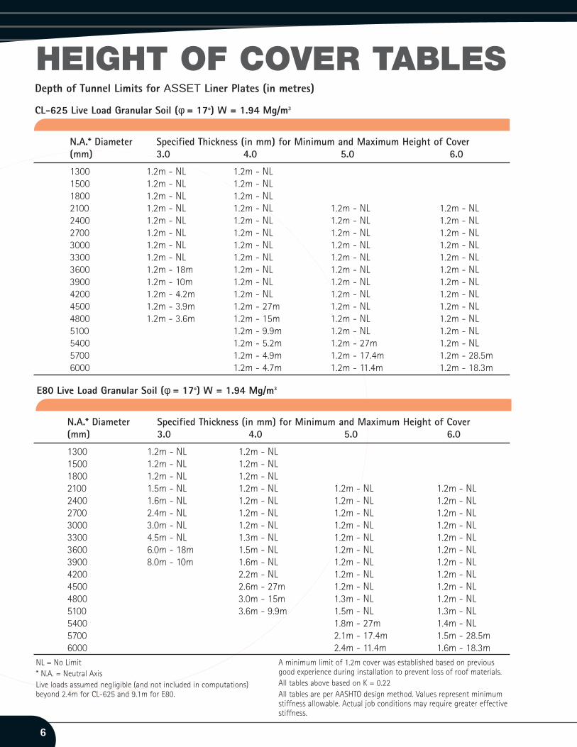
HEIGHT OF COVER TABLESDepth of Tunnel Limits for ASSET Liner Plates (in metres)
CL-625 Live Load Granular Soil (φ = 17o) W = 1.94 Mg/m3
E80 Live Load Granular Soil (φ = 17o) W = 1.94 Mg/m3
N.A.* Diameter Specified Thickness (in mm) for Minimum and Maximum Height of Cover(mm) 3.0 4.0 5.0 6.0
1300 1.2m - NL 1.2m - NL1500 1.2m - NL 1.2m - NL1800 1.2m - NL 1.2m - NL2100 1.5m - NL 1.2m - NL 1.2m - NL 1.2m - NL2400 1.6m - NL 1.2m - NL 1.2m - NL 1.2m - NL2700 2.4m - NL 1.2m - NL 1.2m - NL 1.2m - NL3000 3.0m - NL 1.2m - NL 1.2m - NL 1.2m - NL3300 4.5m - NL 1.3m - NL 1.2m - NL 1.2m - NL3600 6.0m - 18m 1.5m - NL 1.2m - NL 1.2m - NL3900 8.0m - 10m 1.6m - NL 1.2m - NL 1.2m - NL4200 2.2m - NL 1.2m - NL 1.2m - NL4500 2.6m - 27m 1.2m - NL 1.2m - NL4800 3.0m - 15m 1.3m - NL 1.2m - NL5100 3.6m - 9.9m 1.5m - NL 1.3m - NL5400 1.8m - 27m 1.4m - NL5700 2.1m - 17.4m 1.5m - 28.5m6000 2.4m - 11.4m 1.6m - 18.3m
N.A.* Diameter Specified Thickness (in mm) for Minimum and Maximum Height of Cover(mm) 3.0 4.0 5.0 6.0
1300 1.2m - NL 1.2m - NL1500 1.2m - NL 1.2m - NL1800 1.2m - NL 1.2m - NL2100 1.2m - NL 1.2m - NL 1.2m - NL 1.2m - NL2400 1.2m - NL 1.2m - NL 1.2m - NL 1.2m - NL2700 1.2m - NL 1.2m - NL 1.2m - NL 1.2m - NL3000 1.2m - NL 1.2m - NL 1.2m - NL 1.2m - NL3300 1.2m - NL 1.2m - NL 1.2m - NL 1.2m - NL3600 1.2m - 18m 1.2m - NL 1.2m - NL 1.2m - NL3900 1.2m - 10m 1.2m - NL 1.2m - NL 1.2m - NL4200 1.2m - 4.2m 1.2m - NL 1.2m - NL 1.2m - NL4500 1.2m - 3.9m 1.2m - 27m 1.2m - NL 1.2m - NL4800 1.2m - 3.6m 1.2m - 15m 1.2m - NL 1.2m - NL5100 1.2m - 9.9m 1.2m - NL 1.2m - NL5400 1.2m - 5.2m 1.2m - 27m 1.2m - NL5700 1.2m - 4.9m 1.2m - 17.4m 1.2m - 28.5m6000 1.2m - 4.7m 1.2m - 11.4m 1.2m - 18.3m
NL = No Limit* N.A. = Neutral AxisLive loads assumed negligible (and not included in computations)beyond 2.4m for CL-625 and 9.1m for E80.
A minimum limit of 1.2m cover was established based on previousgood experience during installation to prevent loss of roof materials.All tables above based on K = 0.22All tables are per AASHTO design method. Values represent minimumstiffness allowable. Actual job conditions may require greater effectivestiffness.
6

HEIGHT OF COVER TABLES
7
Depth of Tunnel Limits for ASSET Liner Plates (in metres)
CL-625 Live Load Saturated Clay (φ = 8.7o) W = 1.76 Mg/m3
E80 Live Load Saturated Clay (φ = 8.7o) W = 1.76 Mg/m3
N.A.* Diameter Specified Thickness (in mm) for Minimum and Maximum Height of Cover(mm) 3.0 4.0 5.0 6.0
1300 1.2m - NL 1.2m - NL1500 1.2m - NL 1.2m - NL1800 1.2m - NL 1.2m - NL2100 1.5m - NL 1.2m - NL 1.2m - NL 1.2m - NL2400 1.6m - NL 1.2m - NL 1.2m - NL 1.2m - NL2700 2.4m - 14m 1.2m - NL 1.2m - NL 1.2m - NL3000 3.0m - 6m 1.2m - NL 1.2m - NL 1.2m - NL3300 1.3m - 22m 1.2m - NL 1.2m - NL3600 1.5m - 14.2m 1.2m - 42m 1.2m - NL3900 1.6m - 9.9m 1.2m - 26m 1.2m - 38m4200 2.2m - 5.9m 1.2m - 17.6m 1.2m - 24m4500 2.6m - 4.8m 1.2m - 12.4m 1.2m - 17.8m4800 3.0m - 3.7m 1.3m - 9.8m 1.2m - 13.6m5100 1.5m - 7m 1.3m - 10.2m5400 1.8m - 6.3m 1.4m - 7.6m5700 2.1m - 6.1m 1.5m - 7.1m6000 2.4m - 5.7m 1.6m - 6.6m
N.A.* Diameter Specified Thickness (in mm) for Minimum and Maximum Height of Cover(mm) 3.0 4.0 5.0 6.0
1300 1.2m - NL 1.2m - NL1500 1.2m - NL 1.2m - NL1800 1.2m - NL 1.2m - NL2100 1.2m - NL 1.2m - NL 1.2m - NL 1.2m - NL2400 1.2m - NL 1.2m - NL 1.2m - NL 1.2m - NL2700 1.2m - 14m 1.2m - NL 1.2m - NL 1.2m - NL3000 1.2m - 8.3m 1.2m - NL 1.2m - NL 1.2m - NL3300 1.2m - 5.9m 1.2m - 22m 1.2m - NL 1.2m - NL3600 1.2m - 4.8m 1.2m - 14.2m 1.2m - 42m 1.2m - NL3900 1.2m - 4.5m 1.2m - 9.9m 1.2m - 26m 1.2m - 38m4200 1.2m - 4.2m 1.2m - 7.4m 1.2m - 17.6m 1.2m - 24m4500 1.2m - 3.9m 1.2m - 6.3m 1.2m - 12.4m 1.2m - 17.8m4800 1.2m - 3.6m 1.2m - 5.8m 1.2m - 9.8m 1.2m - 13.6m5100 1.2m - 3.4m 1.2m - 5.5m 1.2m - 8.2m 1.2m - 10.2m5400 1.2m - 5.2m 1.2m - 7.3m 1.2m - 8.6m5700 1.2m - 4.9m 1.2m - 6.9m 1.2m - 7.7m6000 1.2m - 4.7m 1.2m - 6.5m 1.2m - 7.3m
NL = No Limit* N.A. = Neutral Axis Live loads assumed negligible (and not included in computations)beyond 2.4m for CL-625 and 9.1m for E80.
A minimum limit of 1.2m cover was established based on previousgood experience during installation to prevent loss of roof materials.All tables above based on K = 0.22All tables are per AASHTO design method. Values represent minimumstiffness allowable. Actual job conditions may require greater effectivestiffness.

Sales Offices:ASSET INTERNATIONAL,STEPHENSON STREET, NEWPORT, SOUTH WALES,NP19 4XHTel: 01633 637504Fax: 01633 290519 TLP/15C/BP/1005
Liner Plate pedestrian/bicycle underpass, installedbeneath a live rail line
Entrance to tunnel with sheeting headwall
Product details and specifications are constantly evolving. This brochure is intended to provide general product information.The product received may not be exactly as shown. Contact an ASSET Sales office for current product data.
Liner Plate used as a signal support base in railroadapplication
38m diameter rib reinforced Liner Plate shaft used forinstallation of a sub surface transformer, 21m deep
Applications for ASSET Tunnel Liner Plate• Tunnels• Relines of failing underground structures• Vertical shafts
• Mine entries• Vertical storage bins